EP2494219B1 - Système de fixation d'un déphaseur d'arbre a cames - Google Patents
Système de fixation d'un déphaseur d'arbre a cames Download PDFInfo
- Publication number
- EP2494219B1 EP2494219B1 EP10778605.5A EP10778605A EP2494219B1 EP 2494219 B1 EP2494219 B1 EP 2494219B1 EP 10778605 A EP10778605 A EP 10778605A EP 2494219 B1 EP2494219 B1 EP 2494219B1
- Authority
- EP
- European Patent Office
- Prior art keywords
- camshaft
- driven part
- fastening arrangement
- tension nut
- end portion
- Prior art date
- Legal status (The legal status is an assumption and is not a legal conclusion. Google has not performed a legal analysis and makes no representation as to the accuracy of the status listed.)
- Not-in-force
Links
- RDYMFSUJUZBWLH-UHFFFAOYSA-N endosulfan Chemical compound C12COS(=O)OCC2C2(Cl)C(Cl)=C(Cl)C1(Cl)C2(Cl)Cl RDYMFSUJUZBWLH-UHFFFAOYSA-N 0.000 title claims 2
- 230000007246 mechanism Effects 0.000 claims description 15
- 229910000639 Spring steel Inorganic materials 0.000 claims description 3
- 239000002184 metal Substances 0.000 claims description 2
- 238000002485 combustion reaction Methods 0.000 description 6
- 230000006835 compression Effects 0.000 description 4
- 238000007906 compression Methods 0.000 description 4
- 239000012530 fluid Substances 0.000 description 4
- 238000004519 manufacturing process Methods 0.000 description 4
- 230000008602 contraction Effects 0.000 description 3
- 230000007704 transition Effects 0.000 description 2
- 238000005452 bending Methods 0.000 description 1
- 238000010276 construction Methods 0.000 description 1
- 230000000694 effects Effects 0.000 description 1
- 230000005489 elastic deformation Effects 0.000 description 1
- 239000003344 environmental pollutant Substances 0.000 description 1
- 230000002349 favourable effect Effects 0.000 description 1
- 239000000446 fuel Substances 0.000 description 1
- 238000005461 lubrication Methods 0.000 description 1
- 231100000719 pollutant Toxicity 0.000 description 1
- 230000010349 pulsation Effects 0.000 description 1
- 230000003313 weakening effect Effects 0.000 description 1
Images


Classifications
-
- F—MECHANICAL ENGINEERING; LIGHTING; HEATING; WEAPONS; BLASTING
- F16—ENGINEERING ELEMENTS AND UNITS; GENERAL MEASURES FOR PRODUCING AND MAINTAINING EFFECTIVE FUNCTIONING OF MACHINES OR INSTALLATIONS; THERMAL INSULATION IN GENERAL
- F16B—DEVICES FOR FASTENING OR SECURING CONSTRUCTIONAL ELEMENTS OR MACHINE PARTS TOGETHER, e.g. NAILS, BOLTS, CIRCLIPS, CLAMPS, CLIPS OR WEDGES; JOINTS OR JOINTING
- F16B41/00—Measures against loss of bolts, nuts, or pins; Measures against unauthorised operation of bolts, nuts or pins
-
- F—MECHANICAL ENGINEERING; LIGHTING; HEATING; WEAPONS; BLASTING
- F01—MACHINES OR ENGINES IN GENERAL; ENGINE PLANTS IN GENERAL; STEAM ENGINES
- F01L—CYCLICALLY OPERATING VALVES FOR MACHINES OR ENGINES
- F01L1/00—Valve-gear or valve arrangements, e.g. lift-valve gear
- F01L1/34—Valve-gear or valve arrangements, e.g. lift-valve gear characterised by the provision of means for changing the timing of the valves without changing the duration of opening and without affecting the magnitude of the valve lift
- F01L1/344—Valve-gear or valve arrangements, e.g. lift-valve gear characterised by the provision of means for changing the timing of the valves without changing the duration of opening and without affecting the magnitude of the valve lift changing the angular relationship between crankshaft and camshaft, e.g. using helicoidal gear
- F01L1/3442—Valve-gear or valve arrangements, e.g. lift-valve gear characterised by the provision of means for changing the timing of the valves without changing the duration of opening and without affecting the magnitude of the valve lift changing the angular relationship between crankshaft and camshaft, e.g. using helicoidal gear using hydraulic chambers with variable volume to transmit the rotating force
-
- F—MECHANICAL ENGINEERING; LIGHTING; HEATING; WEAPONS; BLASTING
- F16—ENGINEERING ELEMENTS AND UNITS; GENERAL MEASURES FOR PRODUCING AND MAINTAINING EFFECTIVE FUNCTIONING OF MACHINES OR INSTALLATIONS; THERMAL INSULATION IN GENERAL
- F16B—DEVICES FOR FASTENING OR SECURING CONSTRUCTIONAL ELEMENTS OR MACHINE PARTS TOGETHER, e.g. NAILS, BOLTS, CIRCLIPS, CLAMPS, CLIPS OR WEDGES; JOINTS OR JOINTING
- F16B39/00—Locking of screws, bolts or nuts
- F16B39/22—Locking of screws, bolts or nuts in which the locking takes place during screwing down or tightening
- F16B39/24—Locking of screws, bolts or nuts in which the locking takes place during screwing down or tightening by means of washers, spring washers, or resilient plates that lock against the object
- F16B39/26—Locking of screws, bolts or nuts in which the locking takes place during screwing down or tightening by means of washers, spring washers, or resilient plates that lock against the object with spring washers fastened to the nut or bolt-head
-
- F—MECHANICAL ENGINEERING; LIGHTING; HEATING; WEAPONS; BLASTING
- F16—ENGINEERING ELEMENTS AND UNITS; GENERAL MEASURES FOR PRODUCING AND MAINTAINING EFFECTIVE FUNCTIONING OF MACHINES OR INSTALLATIONS; THERMAL INSULATION IN GENERAL
- F16D—COUPLINGS FOR TRANSMITTING ROTATION; CLUTCHES; BRAKES
- F16D1/00—Couplings for rigidly connecting two coaxial shafts or other movable machine elements
- F16D1/10—Quick-acting couplings in which the parts are connected by simply bringing them together axially
- F16D1/108—Quick-acting couplings in which the parts are connected by simply bringing them together axially having retaining means rotating with the coupling and acting by interengaging parts, i.e. positive coupling
-
- F—MECHANICAL ENGINEERING; LIGHTING; HEATING; WEAPONS; BLASTING
- F16—ENGINEERING ELEMENTS AND UNITS; GENERAL MEASURES FOR PRODUCING AND MAINTAINING EFFECTIVE FUNCTIONING OF MACHINES OR INSTALLATIONS; THERMAL INSULATION IN GENERAL
- F16D—COUPLINGS FOR TRANSMITTING ROTATION; CLUTCHES; BRAKES
- F16D1/00—Couplings for rigidly connecting two coaxial shafts or other movable machine elements
- F16D1/12—Couplings for rigidly connecting two coaxial shafts or other movable machine elements allowing adjustment of the parts about the axis
-
- F—MECHANICAL ENGINEERING; LIGHTING; HEATING; WEAPONS; BLASTING
- F01—MACHINES OR ENGINES IN GENERAL; ENGINE PLANTS IN GENERAL; STEAM ENGINES
- F01L—CYCLICALLY OPERATING VALVES FOR MACHINES OR ENGINES
- F01L1/00—Valve-gear or valve arrangements, e.g. lift-valve gear
- F01L1/02—Valve drive
- F01L1/04—Valve drive by means of cams, camshafts, cam discs, eccentrics or the like
- F01L1/047—Camshafts
- F01L2001/0475—Hollow camshafts
-
- F—MECHANICAL ENGINEERING; LIGHTING; HEATING; WEAPONS; BLASTING
- F01—MACHINES OR ENGINES IN GENERAL; ENGINE PLANTS IN GENERAL; STEAM ENGINES
- F01L—CYCLICALLY OPERATING VALVES FOR MACHINES OR ENGINES
- F01L1/00—Valve-gear or valve arrangements, e.g. lift-valve gear
- F01L1/34—Valve-gear or valve arrangements, e.g. lift-valve gear characterised by the provision of means for changing the timing of the valves without changing the duration of opening and without affecting the magnitude of the valve lift
- F01L1/344—Valve-gear or valve arrangements, e.g. lift-valve gear characterised by the provision of means for changing the timing of the valves without changing the duration of opening and without affecting the magnitude of the valve lift changing the angular relationship between crankshaft and camshaft, e.g. using helicoidal gear
- F01L1/3442—Valve-gear or valve arrangements, e.g. lift-valve gear characterised by the provision of means for changing the timing of the valves without changing the duration of opening and without affecting the magnitude of the valve lift changing the angular relationship between crankshaft and camshaft, e.g. using helicoidal gear using hydraulic chambers with variable volume to transmit the rotating force
- F01L2001/34423—Details relating to the hydraulic feeding circuit
- F01L2001/34426—Oil control valves
- F01L2001/34433—Location oil control valves
-
- F—MECHANICAL ENGINEERING; LIGHTING; HEATING; WEAPONS; BLASTING
- F16—ENGINEERING ELEMENTS AND UNITS; GENERAL MEASURES FOR PRODUCING AND MAINTAINING EFFECTIVE FUNCTIONING OF MACHINES OR INSTALLATIONS; THERMAL INSULATION IN GENERAL
- F16D—COUPLINGS FOR TRANSMITTING ROTATION; CLUTCHES; BRAKES
- F16D1/00—Couplings for rigidly connecting two coaxial shafts or other movable machine elements
- F16D1/10—Quick-acting couplings in which the parts are connected by simply bringing them together axially
- F16D2001/103—Quick-acting couplings in which the parts are connected by simply bringing them together axially the torque is transmitted via splined connections
Definitions
- the invention is in the technical field of internal combustion engines and relates to a fastening arrangement for fastening a camshaft adjuster to a camshaft.
- the camshaft adjuster comprises a drive part, which can be brought into driving connection with a crankshaft, a driven part rotatably connected to the camshaft, which is rotatably mounted to the drive part, and an adjusting mechanism, by means of which a rotational angle position between driving and driven part can be adjusted.
- the output member is rotatably connected via a central screw with the camshaft.
- gas exchange valves are actuated by cams of a crankshaft-driven camshaft, wherein the timing of the valves can be fixed via the arrangement and shape of the cams.
- About a change of the angular position (phase angle) between Crankshaft and camshaft can be influenced on the timing of the valves, whereby advantageous effects such as a reduction in fuel consumption and the production of pollutants can be achieved.
- camshaft adjuster is usually used for adjusting the phase angle between the crankshaft and camshaft.
- camshaft adjusters comprise a driving part which is drivingly connected to the crankshaft via a drive wheel and a camshaft-fixed driven part, as well as an adjusting mechanism connected between driving and driven part, which transmits the torque from the to the driven part and permits adjustment and fixing of the phase position between the two ,
- a hydraulic adjusting mechanism at least one pair of oppositely acting pressure chambers is provided between the drive and driven part, which are selectively acted upon by pressure medium to rotate input and output part relative to each other and to cause a change in the phase angle between the crankshaft and camshaft.
- Hydraulic camshaft adjusters are for example in the publications DE 202005008264 U1 . EP 1596040 A2 . DE 102005013141 A1 . DE 19908934 A1 and WO 2006/039966 the applicant described in detail.
- Hydraulic adjusting mechanisms usually include an electronic control device, which controls the inflow and outflow of pressure medium on the basis of the current operating state of the internal combustion engine by means of an electromagnetically actuated control valve.
- the control valves comprise a cylindrical valve housing and an axially displaceable inside the valve housing control piston, which is displaceable by an electromagnetically movable plunger against the spring force of a restoring spring element.
- Such control valves are well known as such and for example in the German patent DE 19727180 C2 , the German patent DE 19616973 C2 , as well as the European patent application EP 1 596 041 A2 the applicant described in detail.
- the output part of the camshaft adjuster is provided with a central axial opening, which is penetrated by a screwed with a frontal threaded opening of the camshaft central bolt. Through the central screw, the output part and the camshaft are non-positively connected (rotationally fixed) with each other.
- Such attachment of the camshaft adjuster to the camshaft is for example in German Offenlegungsschrift DE 102004038681 A1 shown.
- valve housing of the control valve also assumes the function of the central screw, so that the output member is rotatably connected via the control valve with the camshaft.
- the object of the present invention is to provide a possibility for fastening the camshaft adjuster by means of a central screw connection to the camshaft, by means of which the known central screw connections are developed in an advantageous manner.
- a fastening arrangement for fastening a camshaft adjuster is shown by means of a central screw connection on a camshaft.
- the mounting arrangement comprises a camshaft adjuster with a crankshaft drive-engageable drive part, a rotatably connected to the camshaft output part, which is rotatably mounted to the drive part, and a particular hydraulic actuator mechanism by which a rotational angular position between the input and output part is optionally adjustable.
- an electromechanical actuating mechanism is provided, as it is for example in the DE 10 2004 038 681 A1 is described
- the driven part is provided with a central axial opening, which is penetrated by an end portion of the camshaft.
- the end portion may be formed integrally with the camshaft or be a separate component which is rotatably connected to the camshaft.
- the end portion of the camshaft on a threaded threaded portion which is screwed to the counter-thread of the output member acting on the clamping nut so that the output member and the camshaft are axially clamped to the rotationally fixed connection.
- the clamping nut is acted upon elastically in the axial direction or relieved in the clamped state in the axial direction, so that a loosening or loosening of the clamping nut is effectively counteracted.
- phase position of input and output part via a hydraulic adjusting mechanism is adjustable, for which purpose usually in a cavity of the camshaft, a control valve is arranged for pressure fluid control, whose connections are aligned as accurately as possible to the terminals of the driven part to ensure efficient fluid transport.
- the camshaft adjuster according to the invention may in particular be a hydraulic rotary piston adjuster, which comprises an outer rotor, which can be brought into drive connection with the crankshaft, and an inner rotor, which is non-rotatably connected to the camshaft.
- inner rotor is mounted in a concentric arrangement with respect to a common axis of rotation rotatably adjustable to the outer rotor, wherein the angular position is adjustable to the outer rotor by means of at least one oppositely acting pressure chamber pair comprising hydraulic adjusting mechanism.
- the driven part is axially braced with or against a camshaft shaped support surface by the clamping nut, wherein between the output member acting on the clamping nut and the driven part an elastically deformable body is arranged, through which the clamping nut is acted upon elastically ,
- the elastically deformable body may in particular be firmly connected to the clamping nut.
- the elastically deformable body is made of spring steel, which can be ensured that the force required for the axial clamping of output part and camshaft force can be transmitted with suitable elastic compression.
- the driven part is clamped axially with a support surface formed by the camshaft by the clamping nut, wherein the clamping nut itself is formed as an elastically deformable body.
- the output member is clamped axially with a formed by the camshaft support surface by the clamping nut, wherein the end portion of the camshaft is provided with a arranged between the support surface and the threaded portion deformation portion which is formed so that it Tightening the clamping nut is elastically deformed.
- This measure also makes possible a particularly simple and cost-effective realization of the fastening arrangement according to the invention in industrial series production, wherein the clamping nut in the tensioned state is acted upon elastically by the deformation section in the axial direction.
- the deformation section of the camshaft may, for example, have a smaller wall thickness than camshaft sections adjacent thereto.
- the driven part is clamped axially with a formed by the camshaft support surface by the clamping nut, wherein the driven part is provided with a clamping nut adjacent to the deformation portion which is formed so that it elastically deformed when tightening the clamping nut becomes.
- the driven part is clamped axially with a formed by the camshaft support surface by the clamping nut, wherein the end portion of the camshaft with a between the support surface and the threaded portion arranged frustoconical cone portion is provided, which is seated the driven part, wherein between the clamping nut and the driven part a friction-enhancing friction element, for example, a friction disc is arranged.
- a friction-enhancing friction element for example, a friction disc is arranged.
- the driven part is clamped axially with a formed by the camshaft support surface by the clamping nut, wherein the end portion of the camshaft is provided with an arranged between the support surface and the threaded portion frusto-conical taper portion, which rests on the driven part, wherein a the clamping nut and the end portion of the camshaft rotatably interconnecting connecting element is arranged.
- a relief of the strained clamping nut can be achieved by the conical section in an advantageous manner, which counteracts a set-related loosening or loosening of the clamping nut.
- Another safeguard against loosening or loosening of the clamping nut is achieved by the connecting element.
- the driven part is clamped axially with a formed by the camshaft support surface by the clamping nut, wherein the end portion of the camshaft is provided with an arranged between the support surface and the threaded portion frusto-conical tapered portion, which rests the driven part, wherein between the clamping nut and the driven part, a wedge ring received in sections in a receptacle of the driven part is arranged.
- the actuating mechanism comprises a hydraulic control valve received in a cavity of the end portion of the camshaft having a valve housing and a control piston received axially displaceably therein, the valve housing being axially displaced by a retaining ring received in an annular groove of the end portion is secured.
- the actuating mechanism comprises a hydraulic control valve received in a cavity of the end portion of the camshaft with a valve housing and a control piston received therein axially displaceable, wherein the valve housing axially by a radial collar formed on the clamping nut is secured.
- a further aspect of the invention relates to a fastening arrangement of a camshaft adjuster with a drive part which can be brought into drive connection with a crankshaft, a driven part rotatably mounted to the drive part, and a hydraulic adjusting mechanism, by means of which a rotational angle position between driving and driven part can be adjusted.
- the output member is provided with a penetrated by an end portion of the camshaft, central axial opening, wherein the output member is welded to the camshaft.
- the hydraulic actuating mechanism comprises a control valve received in a cavity of the end portion of the camshaft having a valve housing and a control piston received axially displaceably therein, the valve housing being axially secured by a retaining ring received in an annular groove of the end portion.
- the invention further extends to an internal combustion engine provided with at least one camshaft adjuster mounting arrangement as described above.
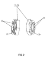
- the generally designated by the reference numeral 1 fastening arrangement comprises a hydraulic Rotationskolbenversteller 2, which as a drive part with a (not shown) crankshaft via a gear 5 and a toothed drive (not shown) can be brought into drive connection outer rotor 3 and as a driven part to the outer rotor 3 rotationally adjustable arranged inner rotor 4, wherein the outer and inner rotor are arranged concentrically about a common axis of rotation 6.
- each pressure chamber is divided into a pair of mutually acting pressure chambers.
- pressure chambers "B" vorseilenden pressure chambers
- pressure chambers "A” pressure chambers
- a rotational angle position between the inner rotor 4 and outer rotor 3 can be adjusted.
- a desired angular position can be maintained, for example by hydraulic clamping of the wings in the pressure chambers.
- the exact mode of operation of such a hydraulic rotary piston adjuster 2 is well-known to the person skilled in the art, for example from the documents cited above, so that it need not be discussed in more detail here.
- the outer rotor 3 forms a pressure-tight housing for the inner rotor 4, wherein the pressure chambers or pressure chambers are closed axially pressure-tight by front side arranged side members 7.
- the outer rotor 4 is screwed to the two side members 7 by axial fixing screws, which in Fig. 1 not shown in detail.
- the inner rotor 4 and the two side members 7 are provided with a central axial opening 8, which is penetrated by an end portion 10 of a camshaft 9.
- the inner rotor 10 of the camshaft 9 sits in clearance fit.
- the end portion 10 is provided with a cavity 11 in which a a total of the reference numeral 12 designated hydraulic control valve is added for the control of pressure medium flows.
- the control valve 12 comprises a hollow-cylindrical valve housing 13 in which a control piston 14 designed as a hollow piston is received in an axially displaceable manner.
- left end face 15 of the control piston 14 engages a valve stem 16 which is rigidly secured to a (not shown) armature of an electromagnet 17.
- valve stem 16 When the armature is energized, the valve stem 16 is axially offset and displaces the control piston 14 in the axial direction against the spring force of a helical compression spring 18. If the armature is not energized, the helical compression spring 18 returns the control piston 14 to its initial position (in Fig. 1 to the left).
- the valve housing 13, the valve stem 16 and a surrounding the valve housing 13 sleeve 19 are provided with a series of grooves and openings to supply communicating with the pressure chambers pressure fluid ports 20 of the inner rotor 4 in the desired manner depending on the position of the control piston 14 with pressure medium or deduce therefrom pressure medium.
- a pressure medium oil of the lubrication circuit is usually used, which can be supplied via pressure medium channels 35. The exact functioning of the control valve 12 need not be discussed here.
- a securing position of the control valve 12 is effected by a circlip 33 received in the cavity 11 in an annular groove 34.
- the circlip 33 simultaneously forms an axial stop for the control piston 14.
- control valve 12 is provided with a check valve 21, by which an idling of the pressure medium paths when switching off the internal combustion engine and an introduction of pressure peaks and pulsations due to alternating torques of the camshaft can be prevented in the oil circuit.
- Fig. 1 is still a coil spring 22 can be seen by the outer and inner rotor 3, 4 when stopping the engine against the friction moments the camshaft can be brought into a favorable for starting the internal combustion engine thermodynamic phase position (base position).
- a rotationally fixed connection of the inner rotor 4 with the camshaft 9 is effected by axial clamping by means of a clamping nut 23.
- a threaded portion 24 of the end portion 10 of the camshaft 9 is provided with an external thread 25 which is screwed to the internal thread 26 of the clamping nut 23.
- the inner rotor 4 is pressed by the clamping nut 23 against a support surface 28 formed by an annular shoulder 27 of the camshaft 9.
- annular ring member 30 is integrally formed on the clamping nut 23 and a female thread 26 bearing, designed in the form of a polygonal head portion 29 and fixedly connected to the head portion 29.
- the ring member 30 is here made of spring steel, for example. It is provided with a plurality of round or, for example, oval openings 31, through which the ring part 30 acquires a certain elastic deformability in the axial direction.
- the ring member 30 comes to rest against an end face 32 of the inner rotor 4, whereby it is pressed against the support surface 28. In this case, the ring member 30 is elastically compressed. If the threaded bandage settles over time, the elastically compressed ring part 30 can compensate for this set loss, so that loosening or loosening of the clamping nut 23 is prevented.
- FIG. 3 taken, wherein a further embodiment of the fastening arrangement according to the invention is shown with reference to a radial sectional view. To avoid unnecessary repetition, only the differences to those in Fig. 1 and 2 illustrated embodiment explained and otherwise referred to the statements there.
- the clamping nut 23 is provided with a radially inwardly directed collar 36, which serves to secure the axial position of the control valve 12 instead of a locking ring.
- the collar 36 serves as an axial stop for the control piston 14th
- FIG. 4 taken, wherein a further embodiment of the fastening arrangement according to the invention is shown with reference to a radial sectional view. To avoid unnecessary repetition, only the differences to those in Fig. 1 and 2 illustrated embodiment explained and otherwise referred to the statements there.
- the clamping nut 23 is formed as a sheet metal forming part and can be elastically deformed during axial clamping. It comprises for this purpose an axial ring portion 37, which carries the internal thread 26 and is connected via a radial transition portion 39 with a support portion 38. If the clamping nut 23 screwed onto the external thread 25 of the threaded portion 24, the support portion 38 comes to rest against the contact surface 32 so that it is moved relative to the ring portion 37 upon further tightening the clamping nut 23 under elastic deformation of the clamping nut 23. If the threaded bandage settles over time, the elastically deformable tensioning nut 23 can compensate for this setting loss so that loosening or loosening of the tensioning nut 23 is prevented.
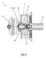
- FIG. 5 taken, wherein a further embodiment of the fastening arrangement according to the invention is shown with reference to a radial sectional view. To avoid unnecessary repetition, only the differences to those in Fig. 1 and 2 illustrated embodiment explained and otherwise referred to the statements there.
- the clamping nut 23 is not connected to an elastically deformable ring member 30.
- the headboard 29 is a rigid with this connected rigid clamping nut collar 41 integrally formed.
- the clamping nut collar 41 bears with its end face via a friction disk 42 on the contact surface 32.
- the friction disc 42 serves to inhibit loosening or loosening of the clamping nut 23.
- the end portion 10 of the camshaft 9 is provided with a (camshaft) deformation portion 40 in the region between the threaded portion 24 and the support surface 28.
- the deformation portion 40 is formed by an outer circumferential (camshaft) annular groove 43, which leads to a weakening of the end portion 10 by reducing the wall thickness.
- the clamping nut collar 41 comes with its end face to rest against the contact surface 32 of the inner rotor 4.
- the elastic deformable deformation portion 40 can compensate for this set loss (by contraction), so that loosening of the tension nut 23 is prevented.
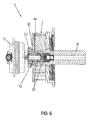
- FIG. 6 taken, wherein a further embodiment of the fastening arrangement according to the invention is shown with reference to a radial sectional view. To avoid unnecessary repetition, only the differences to those in Fig. 1 and 2 illustrated embodiment explained and otherwise referred to the statements there.
- a region of the inner rotor 4, which adjoins the annular part 30 and forms the contact surface 32 hereinafter referred to as (inner rotor) deformation portion 44, formed elastically deformable.
- the deformation section 44 is formed by an enlarged depth of the pressure medium connection 20 designed as an annular groove and adjoining the contact surface 32. If the clamping nut 23 screwed onto the external thread 25 of the threaded portion 24, the ring member 30 comes with its end face to rest against the contact surface 32 of the Inner rotor 4. Upon further tightening of the clamping nut 23, the deformation portion 44 of the inner rotor 4 is elastically compressed due to the axial bracing of the assembly. Over time, when the threaded bandage settles, the elastic deformable deformation portion 44 can compensate for this set loss (by contraction), so that loosening of the tightening nut 23 is prevented.
- FIG. 7 taken, wherein a further embodiment of the fastening arrangement according to the invention is shown with reference to a radial sectional view. To avoid unnecessary repetition, only the differences to those in Fig. 5 illustrated embodiment explained and otherwise referred to the statements there.
- the end portion 10 is provided instead of a deformation portion 40 between the threaded portion 24 and the support surface 28 with a frusto-conical tapered portion 45.
- the axial opening 8 of the inner rotor 4 is designed for this purpose in a fit. If the clamping nut 23 screwed onto the external thread 25 of the threaded portion 24, the clamping nut collar 41 comes with its end face to rest against the contact surface 32 of the inner rotor 4. Upon further tightening the clamping nut 23, the inner rotor 4 is pressed against the support surface 28. In addition, the inner rotor 8 is braced axially and radially at the axial opening 8 with the conical section 45. As a result, the clamping nut 23 is relieved, whereby a setting of the threaded bandage is counteracted.
- FIG. 8 taken, wherein a further embodiment of the fastening arrangement according to the invention is shown with reference to a radial sectional view. To avoid unnecessary repetition, only the differences to those in Fig. 7 illustrated embodiment explained and otherwise referred to the statements there.
- fastening tabs 46 are distributed around the circumference fastening tabs 46 , both with the end portion 10 of the camshaft 9 and with the Clamping nut 23 are rotatably connected.
- the fastening tabs 46 are each received with one end in grooves of the end portion 10, which in FIG. 8th are not shown in detail. With their other end, the fastening tabs 46 are received in tab receptacles 47 of the clamping nut 23.
- the fastening tabs 46 can be introduced after tightening the clamping nut 23 in a simple manner by bending into the Lauschfactn 47.
- FIG. 9 taken, wherein a further embodiment of the fastening arrangement according to the invention is shown with reference to a radial sectional view. To avoid unnecessary repetition, only the differences to those in Fig. 1 and Fig. 2 illustrated embodiment explained and otherwise referred to the statements there.
- the clamping nut 23 is formed only as a head part 29.
- an elastically deformable wedge ring 49 is partially (partially) added. If the clamping nut 23 is screwed onto the external thread 25 of the threaded section 24, an end face of the head part 29 comes to bear against the wedge ring 49, so that it is acted upon. Over time, if the threaded bandage settles, the wedge ring 49 can compensate for this set loss (by contraction) so that loosening or loosening of the clamping nut 23 is prevented. In addition, loosening of the threaded bandage is counteracted by the friction properties of the wedge ring 49.
- FIG. 10 taken, wherein a further embodiment of the fastening arrangement according to the invention is shown with reference to a radial sectional view. To avoid unnecessary repetition, only the differences to those in Fig. 1 and Fig. 2 illustrated embodiment and otherwise on there explained guidance and otherwise referred to the statements there.
- the inner rotor 4 is not axially braced by a clamping nut with the camshaft 9, but welded by a circumferential weld 50 with the end portion 10 of the camshaft 9.
- the control valve 12 is axially secured by the captured in the cavity 11 in an annular groove 34 securing ring 33.
- the fastening arrangement according to the invention thus advantageously makes it possible to effectively counteract loosening or loosening of the clamping nut of a central threaded bandage for axial clamping of the camshaft adjuster with the camshaft, in particular to ensure accurate positioning of the driven part to the camshaft.
Landscapes
- Engineering & Computer Science (AREA)
- General Engineering & Computer Science (AREA)
- Mechanical Engineering (AREA)
- Valve Device For Special Equipments (AREA)
- Valve-Gear Or Valve Arrangements (AREA)
Claims (12)
- Agencement de fixation (1) pour la fixation d'un déphaseur d'arbre à cames (2) sur un arbre à cames (9), comprenant une partie d'entraînement (3) pouvant être amenée en liaison d'entraînement avec un vilebrequin, une partie de sortie (4) connectée de manière solidaire en rotation à l'arbre à cames (9), laquelle est montée de manière réglable en rotation par rapport à la partie d'entraînement (3), ainsi qu'un mécanisme de commande par le biais duquel une position d'angle de rotation entre la partie d'entraînement et la partie de sortie (3, 4) peut être réglée,- la partie de sortie (4) étant pourvue d'une ouverture axiale centrale (8) traversée par une section d'extrémité (10) de l'arbre à cames (9),- la section d'extrémité (10) présentant une section filetée (24) portant un filetage, qui est vissée à un écrou de serrage (23) sollicitant la partie de sortie (4) de telle sorte que la partie de sortie (4) et l'arbre à cames (9) soient serrés axialement en vue de leur connexion solidaire en rotation avec une surface de support (28) formée par l'arbre à cames (9),- l'écrou de serrage (23) étant sollicité élastiquement dans la direction axiale de manière à s'opposer à un relâchement de l'écrou de serrage (23),caractérisé en ce que
un corps déformable élastiquement (30) étant disposé entre l'écrou de serrage (23) sollicitant la partie de sortie (4) et la partie de sortie,
le corps déformable élastiquement (30) est fabriqué en acier à ressort. - Agencement de fixation (1) selon la revendication 1, caractérisé en ce que le corps déformable élastiquement (30) est connecté fixement à l'écrou de serrage (23).
- Agencement de fixation (1) selon la revendication 1, caractérisé en ce que la partie de sortie (4) est serrée axialement par l'écrou de serrage (23) avec une surface de support (28) formée par l'arbre à cames (9), l'écrou de serrage (23) étant lui-même réalisé sous forme de corps déformable élastiquement.
- Agencement de fixation (1) selon la revendication 3, caractérisé en ce que l'écrou de serrage (23) est une pièce formée en tôle.
- Agencement de fixation (1) selon la revendication 1, caractérisé en ce que la section d'extrémité (10) de l'arbre à cames (9) est pourvue d'une section de déformation (40) disposée entre la surface de support (28) et la section filetée (24), laquelle section de déformation est réalisée de telle sorte qu'elle soit déformée élastiquement lors du vissage de l'écrou de serrage (23).
- Agencement de fixation (1) selon la revendication 5, caractérisé en ce que la section de déformation (40) de l'arbre à cames (9) présente une plus faible épaisseur de paroi que des sections d'arbre à cames adjacentes à celle-ci.
- Agencement de fixation (1) selon la revendication 1, caractérisé en ce que la partie de sortie (4) est pourvue d'une section de déformation (44) adjacente à l'écrou de serrage (23), laquelle est réalisée de telle sorte qu'elle soit déformée élastiquement lors du vissage de l'écrou de serrage (23).
- Agencement de fixation (1) selon la revendication 1, caractérisé en ce que la section d'extrémité (10) de l'arbre à cames est munie d'une section conique de forme tronconique (45) disposée entre la surface de support (28) et la section filetée (24), sur laquelle repose la partie de sortie (4), un élément de friction (42) amplifiant le frottement étant disposé entre l'écrou de serrage (23) et la partie de sortie (4).
- Agencement de fixation (1) selon la revendication 1, caractérisé en ce que la section d'extrémité (10) de l'arbre à cames (9) est munie d'une section conique de forme tronconique (45) disposée entre la surface de support (28) et la section filetée (24), sur laquelle repose la partie de sortie (4), un élément de liaison (46) étant prévu, lequel relie l'un à l'autre de manière solidaire en rotation l'écrou de serrage (23) et la section d'extrémité (10) de l'arbre à cames (9).
- Agencement de fixation (1) selon la revendication 1, caractérisé en ce que la section d'extrémité (10) de l'arbre à cames est munie d'une section conique de forme tronconique (45) disposée entre la surface de support (28) et la section filetée (24), sur laquelle repose la partie de sortie (4), une bague clavetée (49) reçue en partie dans un logement (48) de la partie de sortie (4) étant disposée entre l'écrou de serrage (23) et la partie de sortie (4).
- Agencement de fixation (1) selon l'une quelconque des revendications 1 à 10, caractérisé en ce que le mécanisme de commande comprend une soupape de commande hydraulique (12) reçue dans une cavité (11) de la section d'extrémité (10) de l'arbre à cames (9), avec un boîtier de soupape (13) et un piston de commande (14) reçu de manière déplaçable axialement dans celui-ci, le boîtier de soupape (13) étant fixé axialement par une bague de fixation (33) reçue dans une rainure annulaire (34) de la section d'extrémité (10).
- Agencement de fixation (1) selon l'une quelconque des revendications 1 à 10, caractérisé en ce que le mécanisme de commande comprend une soupape de commande hydraulique (12) reçue dans une cavité (11) de la section d'extrémité (10) de l'arbre à cames (9), avec un boîtier de soupape (13) et un piston de commande (14) reçu de manière déplaçable axialement dans celui-ci, le boîtier de soupape (13) étant fixé axialement par un collet radial (36) de l'écrou de serrage (23).
Applications Claiming Priority (2)
| Application Number | Priority Date | Filing Date | Title |
|---|---|---|---|
| DE200910051310 DE102009051310A1 (de) | 2009-10-29 | 2009-10-29 | Befestigungsanordnung eines Nockenwellenverstellers |
| PCT/EP2010/066330 WO2011051378A2 (fr) | 2009-10-29 | 2010-10-28 | Système de fixation d'un déphaseur d'arbre à cames |
Publications (2)
| Publication Number | Publication Date |
|---|---|
| EP2494219A2 EP2494219A2 (fr) | 2012-09-05 |
| EP2494219B1 true EP2494219B1 (fr) | 2014-12-10 |
Family
ID=43572187
Family Applications (1)
| Application Number | Title | Priority Date | Filing Date |
|---|---|---|---|
| EP10778605.5A Not-in-force EP2494219B1 (fr) | 2009-10-29 | 2010-10-28 | Système de fixation d'un déphaseur d'arbre a cames |
Country Status (5)
| Country | Link |
|---|---|
| US (1) | US8899198B2 (fr) |
| EP (1) | EP2494219B1 (fr) |
| CN (2) | CN102597546B (fr) |
| DE (1) | DE102009051310A1 (fr) |
| WO (1) | WO2011051378A2 (fr) |
Families Citing this family (14)
| Publication number | Priority date | Publication date | Assignee | Title |
|---|---|---|---|---|
| US8662039B2 (en) * | 2011-03-16 | 2014-03-04 | Delphi Technologies, Inc. | Camshaft phaser with coaxial control valves |
| DE102011080423A1 (de) * | 2011-08-04 | 2013-02-07 | Schaeffler Technologies AG & Co. KG | Vormontage eines Nockenwellenverstellers |
| DE102012214762B4 (de) | 2012-08-20 | 2017-01-26 | Schaeffler Technologies AG & Co. KG | Befestigungsanordnung zur Verbindung eines Nockenwellenverstellers mit einer Nockenwelle |
| DE102012221876B4 (de) | 2012-11-29 | 2021-01-07 | Schaeffler Technologies AG & Co. KG | Nockenwellenverstellvorrichtung |
| DE102013209166A1 (de) * | 2013-05-17 | 2014-11-20 | Schaeffler Technologies Gmbh & Co. Kg | Zentralventil mit einem Steuerkolben zur Steuerung der Ölversorgung für einen Nockenwellenversteller |
| DE102013114625A1 (de) * | 2013-12-20 | 2015-06-25 | Eto Magnetic Gmbh | Nockenwellenverstellvorrichtung, Verbrennungsmotor sowie Montageverfahren |
| MX2016011909A (es) * | 2014-03-19 | 2016-12-05 | Hitachi Automotive Systems Ltd | Valvula de control para dispositivo de control de sincronizacion de valvula y dispositivo de control de sicronizacion de valvula para motor de combustion interna. |
| DE102014207988B3 (de) | 2014-04-29 | 2015-09-10 | Schaeffler Technologies AG & Co. KG | Elektromagnetische Stellvorrichtung |
| DE102015105337A1 (de) * | 2015-04-08 | 2016-10-13 | Kendrion (Villingen) Gmbh | Elektromagnetischer Aktuator mit klemmfreien Stößeln |
| JP6578896B2 (ja) * | 2015-11-09 | 2019-09-25 | アイシン精機株式会社 | 弁開閉時期制御装置 |
| CN114270163A (zh) * | 2019-10-15 | 2022-04-01 | 深圳市大疆创新科技有限公司 | 内转子组件测试系统以及可移动平台 |
| US11261765B1 (en) * | 2020-08-25 | 2022-03-01 | Borgwamer Inc. | Control valve assembly of a variable cam timing phaser |
| CN112291453B (zh) * | 2020-09-30 | 2022-03-25 | 浙江大华技术股份有限公司 | 角度调节机构以及摄像组件 |
| CN114165528B (zh) * | 2021-11-26 | 2024-01-30 | 合肥恒力装备有限公司 | 一种用于回流焊炉调宽机构的联轴器 |
Family Cites Families (21)
| Publication number | Priority date | Publication date | Assignee | Title |
|---|---|---|---|---|
| US3721220A (en) * | 1970-07-09 | 1973-03-20 | Alfa Romeo Spa | Variator for the setting of the camshafts of an internal combustion engine |
| GB8405204D0 (en) | 1984-02-29 | 1984-04-04 | Exotech Ltd | Fastener spring device |
| FR2582064B1 (fr) * | 1985-05-17 | 1987-06-19 | Renault | Ecrou a zone elastique integre |
| GB8807677D0 (en) * | 1988-03-31 | 1988-05-05 | Wednesbury Charles Ltd | Fasteners |
| DE19616973C2 (de) | 1996-04-27 | 2003-11-06 | Bayerische Motoren Werke Ag | Mehrwege-Schieberventil |
| DE19727180C2 (de) | 1997-06-26 | 2003-12-04 | Hydraulik Ring Gmbh | Hydraulisches Ventil, insbesondere zur Steuerung einer Nockenwellenverstellung in einem Kraftfahrzeug |
| DE19756015A1 (de) * | 1997-12-17 | 1999-06-24 | Porsche Ag | Vorrichtung zur hydraulischen Drehwinkelverstellung einer Welle zu einem Antriebsrad |
| DE19908934A1 (de) | 1999-03-02 | 2000-09-07 | Schaeffler Waelzlager Ohg | Vorrichtung zur Drehwinkelverstellung einer Nockenwelle |
| DE19955507C2 (de) | 1999-11-18 | 2003-04-24 | Daimler Chrysler Ag | Nockenwellensteller für Brennkraftmaschinen |
| JP2003012459A (ja) * | 2001-06-25 | 2003-01-15 | Kao Corp | 化粧料 |
| DE102004038252A1 (de) | 2004-05-14 | 2005-12-15 | Ina-Schaeffler Kg | Steuerventil für eine Vorrichtung zur Veränderung der Steuerzeiten einer Brennkraftmaschine |
| DE502005010369D1 (de) | 2004-05-14 | 2010-11-25 | Schaeffler Kg | Nockenwellenversteller |
| DE102004038681B4 (de) | 2004-08-10 | 2017-06-01 | Schaeffler Technologies AG & Co. KG | Elektromotorischer Nockenwellenversteller |
| DE102004049123A1 (de) | 2004-10-07 | 2006-04-13 | Ina-Schaeffler Kg | Vorrichtung zur Veränderung der Steuerzeiten von Gaswechselventilen einer Brennkraftmaschine |
| DE102005013141B4 (de) | 2005-03-22 | 2017-10-19 | Schaeffler Technologies AG & Co. KG | Vorrichtung zur Nockenwellenverstellung einer Brennkraftmaschine |
| DE202005008264U1 (de) | 2005-05-23 | 2005-08-25 | Ina-Schaeffler Kg | Vorrichtung zur variablen Einstellung der Steuerzeiten von Gaswechselventilen einer Brennkraftmaschine |
| DE102005041393A1 (de) * | 2005-09-01 | 2007-03-08 | Schaeffler Kg | Steuerventil für eine Vorrichtung zur Veränderung der Steuerzeiten einer Brennkraftmaschine |
| DE102005047641A1 (de) * | 2005-10-05 | 2007-04-12 | Schaeffler Kg | Steuerventil für einen Nockenwellenversteller |
| DE102005059860A1 (de) * | 2005-12-15 | 2007-07-05 | Schaeffler Kg | Nockenwellenversteller |
| DE102005060111A1 (de) * | 2005-12-16 | 2007-07-05 | Schaeffler Kg | Nockenwellenverstellerzuleitung |
| JP2009138611A (ja) * | 2007-12-05 | 2009-06-25 | Denso Corp | バルブタイミング調整装置 |
-
2009
- 2009-10-29 DE DE200910051310 patent/DE102009051310A1/de not_active Withdrawn
-
2010
- 2010-10-28 WO PCT/EP2010/066330 patent/WO2011051378A2/fr not_active Ceased
- 2010-10-28 US US13/505,042 patent/US8899198B2/en not_active Expired - Fee Related
- 2010-10-28 CN CN201080049603.0A patent/CN102597546B/zh not_active Expired - Fee Related
- 2010-10-28 EP EP10778605.5A patent/EP2494219B1/fr not_active Not-in-force
- 2010-10-28 CN CN201410314740.2A patent/CN104675834B/zh not_active Expired - Fee Related
Also Published As
| Publication number | Publication date |
|---|---|
| US20120210962A1 (en) | 2012-08-23 |
| DE102009051310A1 (de) | 2011-05-05 |
| EP2494219A2 (fr) | 2012-09-05 |
| US8899198B2 (en) | 2014-12-02 |
| CN102597546A (zh) | 2012-07-18 |
| CN104675834B (zh) | 2018-06-19 |
| WO2011051378A3 (fr) | 2011-10-13 |
| CN104675834A (zh) | 2015-06-03 |
| CN102597546B (zh) | 2014-08-20 |
| WO2011051378A2 (fr) | 2011-05-05 |
Similar Documents
| Publication | Publication Date | Title |
|---|---|---|
| EP2494219B1 (fr) | Système de fixation d'un déphaseur d'arbre a cames | |
| EP1860286B1 (fr) | Arbre à cames | |
| EP2766581B1 (fr) | Arbre à cames et élément fonctionnel destiné à un arbre à cames | |
| DE3810804A1 (de) | Vorrichtung zur relativen winkelverstellung zwischen zwei in antriebsverbindung stehenden wellen | |
| EP2478192B1 (fr) | Dispositif permettant le réglage variable des temps de commande de soupapes d'échange gazeux dans un moteur à combustion interne | |
| DE102009029092A1 (de) | Nockenwellenversteller | |
| DE102004051424A1 (de) | Vorrichtung zur Nockenwellenverstellung einer Brennkraftmaschine und Montagewerkzeug | |
| AT519652B1 (de) | Dichtungsvorrichtung und Hydraulikkolben mit Dichtungsvorrichtung | |
| DE102012202823B4 (de) | Nockenwellenversteller | |
| DE102011077020A1 (de) | Differenzgewindespindel zur Befestigung von Nockenwellenverstellern | |
| DE102014209312B4 (de) | Nockenwellenverstellanordnung, umfassend eine axiale Sicherung mittels einer Spannhülse | |
| DE3942052A1 (de) | Vorrichtung zum verstellen der steuerzeiten | |
| EP2552576B1 (fr) | Homogénéisateur | |
| DE102009051309B4 (de) | Vorrichtung zur variablen Einstellung der Steuerzeiten von Gaswechselventilen einer Brennkraftmaschine | |
| DE102006005333B4 (de) | Ventiltrieb für eine Brennkraftmaschine | |
| DE102004019190A1 (de) | Nockenwellenversteller | |
| EP2536925B1 (fr) | Dispositif de réglage variable des temps de commande des vannes d'échange de gaz d'un moteur à combustion interne | |
| DE102012214764B4 (de) | Befestigungsanordnung zur Verbindung eines Nockenwellenverstellers mit einem Nockenwellenende einer Nockenwelle | |
| DE10013877A1 (de) | Vorrichtung zum Verändern der Steuerzeiten von Gaswechselventilen einer Brennkraftmaschine | |
| DE102010035182A1 (de) | Nockenwellenversteller-Anordnung sowie Nockenwellenversteller | |
| DE102009038662A1 (de) | Ventiltrieb einer Brennkraftmaschine | |
| DE102013021566B4 (de) | Einstellvorrichtung für ein Ventilspiel eines Gaswechselventils und Verfahren zum Einstellen eines Ventilspiels eines Gaswechselventils | |
| DE102009014338A1 (de) | Anordnung mit hydraulischem Nockenwellenversteller | |
| EP1226894A2 (fr) | Dispositif de connection d' une tête d' outil à une broche de serrage | |
| EP0313865A1 (fr) | Pompe d'injection de combustible pour moteurs à combustion interne |
Legal Events
| Date | Code | Title | Description |
|---|---|---|---|
| PUAI | Public reference made under article 153(3) epc to a published international application that has entered the european phase |
Free format text: ORIGINAL CODE: 0009012 |
|
| 17P | Request for examination filed |
Effective date: 20120529 |
|
| AK | Designated contracting states |
Kind code of ref document: A2 Designated state(s): AL AT BE BG CH CY CZ DE DK EE ES FI FR GB GR HR HU IE IS IT LI LT LU LV MC MK MT NL NO PL PT RO RS SE SI SK SM TR |
|
| DAX | Request for extension of the european patent (deleted) | ||
| 17Q | First examination report despatched |
Effective date: 20140121 |
|
| RAP1 | Party data changed (applicant data changed or rights of an application transferred) |
Owner name: SCHAEFFLER TECHNOLOGIES GMBH & CO. KG |
|
| REG | Reference to a national code |
Ref country code: DE Ref legal event code: R079 Ref document number: 502010008474 Country of ref document: DE Free format text: PREVIOUS MAIN CLASS: F16B0041000000 Ipc: F01L0001344000 |
|
| GRAP | Despatch of communication of intention to grant a patent |
Free format text: ORIGINAL CODE: EPIDOSNIGR1 |
|
| RIC1 | Information provided on ipc code assigned before grant |
Ipc: F01L 1/344 20060101AFI20140530BHEP Ipc: F01L 1/047 20060101ALI20140530BHEP |
|
| INTG | Intention to grant announced |
Effective date: 20140704 |
|
| GRAS | Grant fee paid |
Free format text: ORIGINAL CODE: EPIDOSNIGR3 |
|
| GRAA | (expected) grant |
Free format text: ORIGINAL CODE: 0009210 |
|
| AK | Designated contracting states |
Kind code of ref document: B1 Designated state(s): AL AT BE BG CH CY CZ DE DK EE ES FI FR GB GR HR HU IE IS IT LI LT LU LV MC MK MT NL NO PL PT RO RS SE SI SK SM TR |
|
| REG | Reference to a national code |
Ref country code: GB Ref legal event code: FG4D Free format text: NOT ENGLISH |
|
| REG | Reference to a national code |
Ref country code: CH Ref legal event code: EP |
|
| REG | Reference to a national code |
Ref country code: IE Ref legal event code: FG4D Free format text: LANGUAGE OF EP DOCUMENT: GERMAN |
|
| REG | Reference to a national code |
Ref country code: AT Ref legal event code: REF Ref document number: 700772 Country of ref document: AT Kind code of ref document: T Effective date: 20150115 |
|
| REG | Reference to a national code |
Ref country code: DE Ref legal event code: R096 Ref document number: 502010008474 Country of ref document: DE Effective date: 20150122 |
|
| RAP2 | Party data changed (patent owner data changed or rights of a patent transferred) |
Owner name: SCHAEFFLER TECHNOLOGIES AG & CO. KG |
|
| REG | Reference to a national code |
Ref country code: NL Ref legal event code: VDEP Effective date: 20141210 |
|
| REG | Reference to a national code |
Ref country code: NL Ref legal event code: VDEP Effective date: 20141210 |
|
| PG25 | Lapsed in a contracting state [announced via postgrant information from national office to epo] |
Ref country code: NO Free format text: LAPSE BECAUSE OF FAILURE TO SUBMIT A TRANSLATION OF THE DESCRIPTION OR TO PAY THE FEE WITHIN THE PRESCRIBED TIME-LIMIT Effective date: 20150310 Ref country code: LT Free format text: LAPSE BECAUSE OF FAILURE TO SUBMIT A TRANSLATION OF THE DESCRIPTION OR TO PAY THE FEE WITHIN THE PRESCRIBED TIME-LIMIT Effective date: 20141210 Ref country code: ES Free format text: LAPSE BECAUSE OF FAILURE TO SUBMIT A TRANSLATION OF THE DESCRIPTION OR TO PAY THE FEE WITHIN THE PRESCRIBED TIME-LIMIT Effective date: 20141210 Ref country code: FI Free format text: LAPSE BECAUSE OF FAILURE TO SUBMIT A TRANSLATION OF THE DESCRIPTION OR TO PAY THE FEE WITHIN THE PRESCRIBED TIME-LIMIT Effective date: 20141210 |
|
| REG | Reference to a national code |
Ref country code: DE Ref legal event code: R081 Ref document number: 502010008474 Country of ref document: DE Owner name: SCHAEFFLER TECHNOLOGIES AG & CO. KG, DE Free format text: FORMER OWNER: SCHAEFFLER TECHNOLOGIES GMBH & CO. KG, 91074 HERZOGENAURACH, DE Effective date: 20150407 |
|
| REG | Reference to a national code |
Ref country code: LT Ref legal event code: MG4D |
|
| PG25 | Lapsed in a contracting state [announced via postgrant information from national office to epo] |
Ref country code: RS Free format text: LAPSE BECAUSE OF FAILURE TO SUBMIT A TRANSLATION OF THE DESCRIPTION OR TO PAY THE FEE WITHIN THE PRESCRIBED TIME-LIMIT Effective date: 20141210 Ref country code: LV Free format text: LAPSE BECAUSE OF FAILURE TO SUBMIT A TRANSLATION OF THE DESCRIPTION OR TO PAY THE FEE WITHIN THE PRESCRIBED TIME-LIMIT Effective date: 20141210 Ref country code: HR Free format text: LAPSE BECAUSE OF FAILURE TO SUBMIT A TRANSLATION OF THE DESCRIPTION OR TO PAY THE FEE WITHIN THE PRESCRIBED TIME-LIMIT Effective date: 20141210 Ref country code: GR Free format text: LAPSE BECAUSE OF FAILURE TO SUBMIT A TRANSLATION OF THE DESCRIPTION OR TO PAY THE FEE WITHIN THE PRESCRIBED TIME-LIMIT Effective date: 20150311 Ref country code: SE Free format text: LAPSE BECAUSE OF FAILURE TO SUBMIT A TRANSLATION OF THE DESCRIPTION OR TO PAY THE FEE WITHIN THE PRESCRIBED TIME-LIMIT Effective date: 20141210 |
|
| PG25 | Lapsed in a contracting state [announced via postgrant information from national office to epo] |
Ref country code: NL Free format text: LAPSE BECAUSE OF FAILURE TO SUBMIT A TRANSLATION OF THE DESCRIPTION OR TO PAY THE FEE WITHIN THE PRESCRIBED TIME-LIMIT Effective date: 20141210 |
|
| PG25 | Lapsed in a contracting state [announced via postgrant information from national office to epo] |
Ref country code: SK Free format text: LAPSE BECAUSE OF FAILURE TO SUBMIT A TRANSLATION OF THE DESCRIPTION OR TO PAY THE FEE WITHIN THE PRESCRIBED TIME-LIMIT Effective date: 20141210 Ref country code: CZ Free format text: LAPSE BECAUSE OF FAILURE TO SUBMIT A TRANSLATION OF THE DESCRIPTION OR TO PAY THE FEE WITHIN THE PRESCRIBED TIME-LIMIT Effective date: 20141210 Ref country code: RO Free format text: LAPSE BECAUSE OF FAILURE TO SUBMIT A TRANSLATION OF THE DESCRIPTION OR TO PAY THE FEE WITHIN THE PRESCRIBED TIME-LIMIT Effective date: 20141210 Ref country code: PT Free format text: LAPSE BECAUSE OF FAILURE TO SUBMIT A TRANSLATION OF THE DESCRIPTION OR TO PAY THE FEE WITHIN THE PRESCRIBED TIME-LIMIT Effective date: 20150410 Ref country code: EE Free format text: LAPSE BECAUSE OF FAILURE TO SUBMIT A TRANSLATION OF THE DESCRIPTION OR TO PAY THE FEE WITHIN THE PRESCRIBED TIME-LIMIT Effective date: 20141210 |
|
| PG25 | Lapsed in a contracting state [announced via postgrant information from national office to epo] |
Ref country code: IS Free format text: LAPSE BECAUSE OF FAILURE TO SUBMIT A TRANSLATION OF THE DESCRIPTION OR TO PAY THE FEE WITHIN THE PRESCRIBED TIME-LIMIT Effective date: 20150410 Ref country code: PL Free format text: LAPSE BECAUSE OF FAILURE TO SUBMIT A TRANSLATION OF THE DESCRIPTION OR TO PAY THE FEE WITHIN THE PRESCRIBED TIME-LIMIT Effective date: 20141210 |
|
| REG | Reference to a national code |
Ref country code: DE Ref legal event code: R097 Ref document number: 502010008474 Country of ref document: DE |
|
| PLBE | No opposition filed within time limit |
Free format text: ORIGINAL CODE: 0009261 |
|
| STAA | Information on the status of an ep patent application or granted ep patent |
Free format text: STATUS: NO OPPOSITION FILED WITHIN TIME LIMIT |
|
| PG25 | Lapsed in a contracting state [announced via postgrant information from national office to epo] |
Ref country code: DK Free format text: LAPSE BECAUSE OF FAILURE TO SUBMIT A TRANSLATION OF THE DESCRIPTION OR TO PAY THE FEE WITHIN THE PRESCRIBED TIME-LIMIT Effective date: 20141210 |
|
| 26N | No opposition filed |
Effective date: 20150911 |
|
| PG25 | Lapsed in a contracting state [announced via postgrant information from national office to epo] |
Ref country code: IT Free format text: LAPSE BECAUSE OF FAILURE TO SUBMIT A TRANSLATION OF THE DESCRIPTION OR TO PAY THE FEE WITHIN THE PRESCRIBED TIME-LIMIT Effective date: 20141210 |
|
| PG25 | Lapsed in a contracting state [announced via postgrant information from national office to epo] |
Ref country code: SI Free format text: LAPSE BECAUSE OF FAILURE TO SUBMIT A TRANSLATION OF THE DESCRIPTION OR TO PAY THE FEE WITHIN THE PRESCRIBED TIME-LIMIT Effective date: 20141210 |
|
| PG25 | Lapsed in a contracting state [announced via postgrant information from national office to epo] |
Ref country code: LU Free format text: LAPSE BECAUSE OF FAILURE TO SUBMIT A TRANSLATION OF THE DESCRIPTION OR TO PAY THE FEE WITHIN THE PRESCRIBED TIME-LIMIT Effective date: 20151028 |
|
| REG | Reference to a national code |
Ref country code: CH Ref legal event code: PL |
|
| GBPC | Gb: european patent ceased through non-payment of renewal fee |
Effective date: 20151028 |
|
| PG25 | Lapsed in a contracting state [announced via postgrant information from national office to epo] |
Ref country code: MC Free format text: LAPSE BECAUSE OF FAILURE TO SUBMIT A TRANSLATION OF THE DESCRIPTION OR TO PAY THE FEE WITHIN THE PRESCRIBED TIME-LIMIT Effective date: 20141210 |
|
| REG | Reference to a national code |
Ref country code: IE Ref legal event code: MM4A |
|
| PG25 | Lapsed in a contracting state [announced via postgrant information from national office to epo] |
Ref country code: CH Free format text: LAPSE BECAUSE OF NON-PAYMENT OF DUE FEES Effective date: 20151031 Ref country code: LI Free format text: LAPSE BECAUSE OF NON-PAYMENT OF DUE FEES Effective date: 20151031 Ref country code: GB Free format text: LAPSE BECAUSE OF NON-PAYMENT OF DUE FEES Effective date: 20151028 |
|
| REG | Reference to a national code |
Ref country code: FR Ref legal event code: ST Effective date: 20160630 |
|
| PG25 | Lapsed in a contracting state [announced via postgrant information from national office to epo] |
Ref country code: FR Free format text: LAPSE BECAUSE OF NON-PAYMENT OF DUE FEES Effective date: 20151102 |
|
| PG25 | Lapsed in a contracting state [announced via postgrant information from national office to epo] |
Ref country code: IE Free format text: LAPSE BECAUSE OF NON-PAYMENT OF DUE FEES Effective date: 20151028 |
|
| REG | Reference to a national code |
Ref country code: AT Ref legal event code: MM01 Ref document number: 700772 Country of ref document: AT Kind code of ref document: T Effective date: 20151028 |
|
| PG25 | Lapsed in a contracting state [announced via postgrant information from national office to epo] |
Ref country code: AT Free format text: LAPSE BECAUSE OF NON-PAYMENT OF DUE FEES Effective date: 20151028 |
|
| PG25 | Lapsed in a contracting state [announced via postgrant information from national office to epo] |
Ref country code: HU Free format text: LAPSE BECAUSE OF FAILURE TO SUBMIT A TRANSLATION OF THE DESCRIPTION OR TO PAY THE FEE WITHIN THE PRESCRIBED TIME-LIMIT; INVALID AB INITIO Effective date: 20101028 Ref country code: SM Free format text: LAPSE BECAUSE OF FAILURE TO SUBMIT A TRANSLATION OF THE DESCRIPTION OR TO PAY THE FEE WITHIN THE PRESCRIBED TIME-LIMIT Effective date: 20141210 Ref country code: BG Free format text: LAPSE BECAUSE OF FAILURE TO SUBMIT A TRANSLATION OF THE DESCRIPTION OR TO PAY THE FEE WITHIN THE PRESCRIBED TIME-LIMIT Effective date: 20141210 |
|
| PG25 | Lapsed in a contracting state [announced via postgrant information from national office to epo] |
Ref country code: CY Free format text: LAPSE BECAUSE OF FAILURE TO SUBMIT A TRANSLATION OF THE DESCRIPTION OR TO PAY THE FEE WITHIN THE PRESCRIBED TIME-LIMIT Effective date: 20141210 |
|
| PG25 | Lapsed in a contracting state [announced via postgrant information from national office to epo] |
Ref country code: BE Free format text: LAPSE BECAUSE OF NON-PAYMENT OF DUE FEES Effective date: 20151031 |
|
| PG25 | Lapsed in a contracting state [announced via postgrant information from national office to epo] |
Ref country code: MT Free format text: LAPSE BECAUSE OF FAILURE TO SUBMIT A TRANSLATION OF THE DESCRIPTION OR TO PAY THE FEE WITHIN THE PRESCRIBED TIME-LIMIT Effective date: 20141210 Ref country code: TR Free format text: LAPSE BECAUSE OF FAILURE TO SUBMIT A TRANSLATION OF THE DESCRIPTION OR TO PAY THE FEE WITHIN THE PRESCRIBED TIME-LIMIT Effective date: 20141210 |
|
| PG25 | Lapsed in a contracting state [announced via postgrant information from national office to epo] |
Ref country code: MK Free format text: LAPSE BECAUSE OF FAILURE TO SUBMIT A TRANSLATION OF THE DESCRIPTION OR TO PAY THE FEE WITHIN THE PRESCRIBED TIME-LIMIT Effective date: 20141210 |
|
| PG25 | Lapsed in a contracting state [announced via postgrant information from national office to epo] |
Ref country code: AL Free format text: LAPSE BECAUSE OF FAILURE TO SUBMIT A TRANSLATION OF THE DESCRIPTION OR TO PAY THE FEE WITHIN THE PRESCRIBED TIME-LIMIT Effective date: 20141210 |
|
| PGFP | Annual fee paid to national office [announced via postgrant information from national office to epo] |
Ref country code: DE Payment date: 20211221 Year of fee payment: 12 |
|
| REG | Reference to a national code |
Ref country code: DE Ref legal event code: R119 Ref document number: 502010008474 Country of ref document: DE |
|
| P01 | Opt-out of the competence of the unified patent court (upc) registered |
Effective date: 20230522 |
|
| PG25 | Lapsed in a contracting state [announced via postgrant information from national office to epo] |
Ref country code: DE Free format text: LAPSE BECAUSE OF NON-PAYMENT OF DUE FEES Effective date: 20230503 |