EP2494253B1 - Sattelklemme mit elektrischer bindungseigenschaft - Google Patents
Sattelklemme mit elektrischer bindungseigenschaft Download PDFInfo
- Publication number
- EP2494253B1 EP2494253B1 EP10773792.6A EP10773792A EP2494253B1 EP 2494253 B1 EP2494253 B1 EP 2494253B1 EP 10773792 A EP10773792 A EP 10773792A EP 2494253 B1 EP2494253 B1 EP 2494253B1
- Authority
- EP
- European Patent Office
- Prior art keywords
- segment
- extending
- tube
- saddle clamp
- electrical contact
- Prior art date
- Legal status (The legal status is an assumption and is not a legal conclusion. Google has not performed a legal analysis and makes no representation as to the accuracy of the status listed.)
- Active
Links
Images


Classifications
-
- F—MECHANICAL ENGINEERING; LIGHTING; HEATING; WEAPONS; BLASTING
- F16—ENGINEERING ELEMENTS AND UNITS; GENERAL MEASURES FOR PRODUCING AND MAINTAINING EFFECTIVE FUNCTIONING OF MACHINES OR INSTALLATIONS; THERMAL INSULATION IN GENERAL
- F16L—PIPES; JOINTS OR FITTINGS FOR PIPES; SUPPORTS FOR PIPES, CABLES OR PROTECTIVE TUBING; MEANS FOR THERMAL INSULATION IN GENERAL
- F16L3/00—Supports for pipes, cables or protective tubing, e.g. hangers, holders, clamps, cleats, clips, brackets
-
- F—MECHANICAL ENGINEERING; LIGHTING; HEATING; WEAPONS; BLASTING
- F16—ENGINEERING ELEMENTS AND UNITS; GENERAL MEASURES FOR PRODUCING AND MAINTAINING EFFECTIVE FUNCTIONING OF MACHINES OR INSTALLATIONS; THERMAL INSULATION IN GENERAL
- F16L—PIPES; JOINTS OR FITTINGS FOR PIPES; SUPPORTS FOR PIPES, CABLES OR PROTECTIVE TUBING; MEANS FOR THERMAL INSULATION IN GENERAL
- F16L3/00—Supports for pipes, cables or protective tubing, e.g. hangers, holders, clamps, cleats, clips, brackets
- F16L3/08—Supports for pipes, cables or protective tubing, e.g. hangers, holders, clamps, cleats, clips, brackets substantially surrounding the pipe, cable or protective tubing
- F16L3/10—Supports for pipes, cables or protective tubing, e.g. hangers, holders, clamps, cleats, clips, brackets substantially surrounding the pipe, cable or protective tubing divided, i.e. with two members engaging the pipe, cable or protective tubing
- F16L3/1091—Supports for pipes, cables or protective tubing, e.g. hangers, holders, clamps, cleats, clips, brackets substantially surrounding the pipe, cable or protective tubing divided, i.e. with two members engaging the pipe, cable or protective tubing with two members, the two members being fixed to each other with fastening members on each side
-
- H—ELECTRICITY
- H01—ELECTRIC ELEMENTS
- H01R—ELECTRICALLY-CONDUCTIVE CONNECTIONS; STRUCTURAL ASSOCIATIONS OF A PLURALITY OF MUTUALLY-INSULATED ELECTRICAL CONNECTING ELEMENTS; COUPLING DEVICES; CURRENT COLLECTORS
- H01R4/00—Electrically-conductive connections between two or more conductive members in direct contact, i.e. touching one another; Means for effecting or maintaining such contact; Electrically-conductive connections having two or more spaced connecting locations for conductors and using contact members penetrating insulation
- H01R4/28—Clamped connections, spring connections
- H01R4/38—Clamped connections, spring connections utilising a clamping member acted on by screw or nut
- H01R4/46—Clamping area between two screws placed side by side
-
- H—ELECTRICITY
- H01—ELECTRIC ELEMENTS
- H01R—ELECTRICALLY-CONDUCTIVE CONNECTIONS; STRUCTURAL ASSOCIATIONS OF A PLURALITY OF MUTUALLY-INSULATED ELECTRICAL CONNECTING ELEMENTS; COUPLING DEVICES; CURRENT COLLECTORS
- H01R4/00—Electrically-conductive connections between two or more conductive members in direct contact, i.e. touching one another; Means for effecting or maintaining such contact; Electrically-conductive connections having two or more spaced connecting locations for conductors and using contact members penetrating insulation
- H01R4/58—Electrically-conductive connections between two or more conductive members in direct contact, i.e. touching one another; Means for effecting or maintaining such contact; Electrically-conductive connections having two or more spaced connecting locations for conductors and using contact members penetrating insulation characterised by the form or material of the contacting members
- H01R4/64—Connections between or with conductive parts having primarily a non-electric function, e.g. frame, casing, rail
- H01R4/643—Connections between or with conductive parts having primarily a non-electric function, e.g. frame, casing, rail for rigid cylindrical bodies
-
- B—PERFORMING OPERATIONS; TRANSPORTING
- B64—AIRCRAFT; AVIATION; COSMONAUTICS
- B64D—EQUIPMENT FOR FITTING IN OR TO AIRCRAFT; FLIGHT SUITS; PARACHUTES; ARRANGEMENT OR MOUNTING OF POWER PLANTS OR PROPULSION TRANSMISSIONS IN AIRCRAFT
- B64D37/00—Arrangements in connection with fuel supply for power plant
- B64D37/32—Safety measures not otherwise provided for, e.g. preventing explosive conditions
Definitions
- the present invention relates to clamping structures, and more particularly to a saddle clamp adapted to support metal piping or tubing such as a fuel tube or the like in an aircraft or other environment of use. More particularly, the present invention relates to a saddle clamp providing electrical contact between the clamped tubing and a metal support frame or other electrical contact structure.
- a saddle clamp according to the preamble of independent claim 1 is known from document EP-A-0 139 980 .
- the present invention offers advantages and alternatives over the prior art by providing a saddle clamp which incorporates internal electrical bonding elements adapted to maintain electrical contact with a clamped tube structure without transferring structural load between the tube and the electrical bonding components. Electrical contact connections are thereby maintained without imparting sliding wear to the tubing and the need to use external electrical contact wire connections is reduced or eliminated. Accordingly, such an arrangement substantially reduces complexity while providing enhanced electrical coupling and charge dissipation.
- the present invention provides a saddle clamp providing electrical bonding with a tube secured in place within the saddle clamp.
- the saddle clamp includes a base segment adapted for operative connection to a mounting bracket and an arch segment extending away from the base segment.
- the arch segment has an inner tube contacting surface.
- the inner tube contacting surface includes at least one surface groove and at least one window opening extends through the arch segment to define a passageway from the inner tube contacting surface to the exterior of the arch segment.
- At least one electrical contact element extends between portions of the inner tube contacting surface.
- the electrical contact element includes a tube contact segment disposed in opposing relation to a portion of the surface groove.
- the electrical contact element further includes a proximal portion extending through the window opening. The proximal portion is electrically connected to the mounting bracket to transmit electrical charge from the tube.
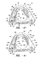
- FIG. 1 an improved exemplary tube clamping system 10 is shown.
- the exemplary tube clamping system 10 incorporates a metal bracket 12 which may be attached to a portion of a metal support structure (not shown) by use of connection bolts 14 extending through attachment openings 16 in a manner as will be well known to those of skill in the art.
- the support structure may be a portion of an aircraft frame although the clamping system 10 may likewise be used in conjunction with virtually any support structure arrangement in numerous alternative environments of use. Without limitation, such alternative environments of use may include petrochemical plants, ground-based fuel storage depots, fuel tanker trucks and the like.
- the exemplary tube clamping system 10 includes a saddle clamp 20 which is adapted for disposition in supporting wrap-around relation to a metal tube 22 so as to hold the tube firmly in place.
- the tube 22 may be a fuel line used in the transport of jet fuel from storage tanks to engines in an aircraft. Tubes of aluminum-based alloys may be particularly preferred due to low weight, although other materials may be used if desired.
- the exemplary saddle clamp 20 includes an axial passageway 24 ( FIG. 2 ) for receipt and retention of the tube 22. In the illustrated configuration, lateral feet 28 project radially outwardly away from the axial passageway 24 for disposition in overlying relation to the surface of the bracket 12.
- each of the lateral feet 28 includes one or more acceptance openings for receipt of a metal coupling fastener 30 which extends between the saddle clamp 20 and the underlying bracket 12 to establish both physical and electrical connection between the saddle clamp 20 and the bracket 12.
- a metal coupling fastener 30 which extends between the saddle clamp 20 and the underlying bracket 12 to establish both physical and electrical connection between the saddle clamp 20 and the bracket 12.
- the coupling fastener is illustrated as a bolt, it is contemplated that virtually any fastener structure that provides electrical and physical connectivity with the bracket 12 may be used.
- the saddle clamp 20 has a two-part design including a base segment 32 and an overlying arch segment 34.
- the base segment 32 includes a platform 35 and a raised support cradle 36 extending upwardly away from the platform 35.
- the raised support cradle 36 includes a pair of lateral arm projections 38 extending upwardly away from the platform 35 with a depressed curved surface 37 running between the arm projections to define the bottom of the axial passageway 24 providing cradling support for the tube 22.
- Segments of the platform 35 project outboard from both sides of the support cradle 36 to define lower portions of the lateral feet 28.
- Acceptance openings 39 extend through the outboard portions of the base 32 for receipt of the coupling fasteners 30 upon final assembly as will be described further hereinafter.
- the base segment 32 may be formed from any suitable plastic material such as heat stabilized polyamide, polyester, ABS or the like as may be desired. In this regard, Nylon 6/6 may be particularly preferred.
- the base segment 32 may be formed as a unitary structure by techniques such as injection molding or the like. Of course, other materials of construction and formation techniques may be used if desired.
- the interior of the arch segment 34 is adapted to fit in sliding relation over the support cradle 36 such that outer surfaces of the lateral arm projections 38 are disposed in close, opposing relation to the lower inner surfaces of the arch segment 34.
- the interior of the arch segment 34 is preferably defined by an upper curved surface forming the top of the axial passageway 24 with substantially straight lower segments for disposition in opposing relation to outer surfaces of the lateral arm projections 38 on the support cradle 36.
- the inner surface of the arch segment 34 includes surface grooves 40 disposed on either side of the arch segment 34.
- the surface grooves 40 extend circumferentially along the inner surface of the arch segment 34.
- the surface grooves 40 may have a substantially flat-bottom construction, although other configurations may be used if desired.
- the surface grooves 40 may extend along the segment of the inner surface forming the transition between the upper curved surface and the adjacent lower straight surfaces on each side of the arch segment. In this regard, the surface grooves 40 preferably intersect with window openings 44 on either side of the arch segment 34.
- the window openings 44 define passageways between the interior and the exterior of the arch segment 34 and are preferably disposed at positions such that they are at least partially covered by outer surfaces of the arm projections 38 of the support cradle 36 when the saddle clamp 20 is in the assembled condition as shown in FIG. 2 .
- one or more raised ridges 42 may extend longitudinally along the length of the surface grooves 40. However, such raised ridges may likewise be eliminated if desired. As will be described further hereinafter, such raised ridges may promote seated acceptance of electrical contact strips within the surface grooves 40 during use.
- the exterior of the arch segment 34 includes a pair of circumferential raised walls 46 which are spaced apart in the axial direction of the clamp to define a circumferential depression 47 between the circumferential raised walls 46.
- the circumferential raised walls 46 may have a generally arched configuration with variable height relative to the circumferential depression 47 about the circumference of the arch segment 34. As shown, the height difference between the raised walls 46 and the circumferential depression 47 may be greatest at the ends of the legs in which the window openings 44 are located thereby providing additional strength in those zones with little or no differential height at the top of the arch.
- the arch segment 34 includes lateral platform projections 48 which define upper portions of the lateral feet 28.
- acceptance openings 49 extend through the platform projections 48 for alignment with the acceptance openings 39 in the platform 35 of the base segment 32.
- the coupling fastener 30 may run through the aligned acceptance openings 39, 49 for connection with the bracket 12.
- the acceptance openings 49 in the platform projections 48 are oriented at positions between lower portions of the circumferential raised walls 46.
- the coupling fastener 30 is seated between raised wall segments thereby providing additional protection against damage during use.
- the arch segment 34 may be formed from any suitable plastic material such as heat stabilized polyamide, polyester, ABS or the like as may be desired. In this regard, Nylon 6/6 may be particularly preferred.
- the material forming the arch segment 34 may be the same as the material forming the base segment 32 although different materials may be used if desired.
- the arch segment 34 may be formed as a unitary structure by techniques such as injection molding or the like. Of course, other materials of construction and formation techniques may be used if desired.
- one or more conductive electrical contact elements 50 is disposed at the interior of the arch segment 34 extending in crossing relation between portions of the inner surface surrounding the axial passageway 24.
- the electrical contact elements 50 may be metal strips of substantially flat ribbon configuration formed from thin, flexible, spring-like material. Such structures may be formed by techniques such as stamping or other metal forming processes.
- One exemplary material which may be used for formation of such metal strips is a beryllium-copper alloy with a cadmium coating, although other metallic or non-metallic materials possessing substantial resiliency and electrical conductivity may be used if desired.
- the electrical contact elements 50 each include a tube contact segment 52 extending between surfaces at the perimeter of the axial passageway 24.
- Each of the electrical contact elements 50 preferably has an effective width which is slightly less than the width of the opposing surface groove 40 such that the electrical contact elements can be received fully within the opposing surface grooves upon the application of force in the radial direction.
- a longitudinal slot 54 extends along the tube contact segment 52 thereby causing the tube contact segment to have a split construction.
- the slot 54 may extend partially along the length of the electrical contact element 50 and preferably has a width adequate to accept the raised ridge 42 in the opposing surface groove 40 when the tube contact segment 52 is pressed into the surface groove 40.
- the electrical contact elements 50 each include a distal portion 56 secured in embedded relation within the curved portion of the arch segment 34 of the saddle clamp 20.
- an embedded relation may be established by press fitting the distal portion 56 into an acceptance slot at the interior of the arch segment.
- other techniques for anchoring the electrical contact elements 50 in place may likewise be used.
- each of the electrical contact elements 50 includes a proximal portion 58 which extends between an outer surface of the support cradle 36 and the opposing inner surface of the arch segment 34.
- the proximal portion 58 extends through the window opening 44 and is ultimately anchored in place at the surface of the platform projection 48 by the coupling fastener 30 which projects through an eyelet opening positioned in alignment with acceptance openings 39, 49.
- the coupling fastener 30 is inserted through the opening in the proximal portion 58, and into engagement with the bracket 12, a continuous electrical connection is established between the electrical contact element 50 and bracket 12 as well as with the frame upon which the bracket is mounted.
- static charge may be dissipated from the tube 22 by the contact elements 50.
- the exemplary embodiment employs two contact elements 50, a larger or smaller number may be used as desired.
- the tube contact segments 52 of the contact elements 50 are flexed to an inwardly bowed configuration. As will be appreciated, such a configuration causes portions of the tube contact segments to project to a radially inward position within the axial passageway 24.
- the electrical contact elements 50 will contact the outer surface of the tube 22 and the tube contact segments 52 are urged radially outwardly towards the perimeter of the arch segment.
- the tube contact segments 52 are pressed outwardly, they conform about the surface of the tube 22 and apply a continuous biasing force against the tube surface.
- the tube contact segments 52 are ultimately pressed into the opposing surface grooves 40.
- the spring-like materials forming the electrical contact elements 50 may be substantially harder than the material forming the tube 22 being clamped. However, because the tube contact segments 52 are pressed into the surface grooves 40, the electrical contact elements 50 are prevented from substantially damaging the tube 22 during use.
- the surface grooves 40 are preferably slightly deeper than the thickness of the corresponding electrical contact elements 50.
- the inner surface of the tube contact segments 52 moves to a position substantially flush with the adjacent inner surfaces of the arch segment 34.
- the tube contact segments 52 do not form a raised abrasive surface. Nonetheless, electrical contact is maintained due to the continuous outward biasing force provided by the tube contact segments 52. In this condition the structural load continues to be carried between the low friction inner surface of the arch segment 34 and the outer surface of the tube 22.
- FIG. 4 illustrates an alternative embodiment of the present invention wherein elements corresponding to those previously described are designated by corresponding reference numbers increased by 100.
- This embodiment operates in the same manner as previously described but incorporates electrical contact elements 150 having substantially linear tube contact segments 152.
- the tube contact segments 152 may apply a slightly lower inwardly biasing force and may tend to conform about the tube with slightly less resistance. It is contemplated that such a structure may be particularly beneficial for larger diameter tubes or in environments where low biasing forces against the tube are considered desirable.
Landscapes
- Engineering & Computer Science (AREA)
- General Engineering & Computer Science (AREA)
- Mechanical Engineering (AREA)
- Supports For Pipes And Cables (AREA)
- Clamps And Clips (AREA)
Claims (15)
- Sattelklemme (20; 120), die eine elektrische Kontaktierung mit einem Rohr (22), das an seinem Ort innerhalb der Sattelklemme befestigt ist, bereitstellt, wobei die Sattelklemme Folgendes umfasst:ein Basissegment (32; 132), das dafür ausgelegt ist, mit einem Montagewinkel (12) betriebstechnisch verbunden zu werden; undein Bogensegment (34; 134), das sich von dem Basissegment (32; 132) weg erstreckt, wobei das Bogensegment eine innere Rohrkontaktherstellungsoberfläche besitzt, wobei wenigstens eine Fensteröffnung (44) einen Durchlass von der inneren Rohrkontaktherstellungsoberfläche zu einer äußeren Umgebung des Bogensegments (34; 134) definiert, und wenigstens ein Element (50; 150) für elektrischen Kontakt besitzt, das sich zwischen Abschnitten der inneren Rohrkontaktherstellungsoberfläche erstreckt, wobei das wenigstens eine Element (50; 150) für elektrischen Kontakt ferner einen proximalen Abschnitt (58; 158) aufweist, der sich durch die wenigstens eine Fensteröffnung (44) erstreckt, wobei der proximale Abschnitt mit dem Montagewinkel (12) elektrisch verbunden ist, um elektrische Ladung von dem Rohr (22) zu übertragen,dadurch gekennzeichnet, dassdie innere Rohrkontaktherstellungsoberfläche wenigstens eine Oberflächennut (40; 140) aufweist, wobei die wenigstens eine Fensteröffnung (44) sich durch das Bogensegment (34; 134) erstreckt; wobei das wenigstens eine Element (50; 150) für elektrischen Kontakt ein Rohrkontaktsegment (52; 152) aufweist, das in entgegengesetzter Beziehung zu einem Abschnitt der wenigstens einen Oberflächennut (40; 140) angeordnet ist, wobei bei einem Befestigen des Rohrs (22) an seinem Ort das wenigstens eine Rohrkontaktsegment (52; 152) in die wenigstens eine Oberflächennut (40; 140) gepresst wird, so dass das Rohrkontaktsegment (52; 152) im Wesentlichen bündig mit der inneren Rohrkontaktherstellungsoberfläche des Bogensegments (34; 134) orientiert werden kann, während das Rohrkontaktsegment (52; 152) eine ununterbrochene Vorbelastungskraft auf das Rohr ausübt.
- Sattelklemme nach Anspruch 1, wobei das Basissegment (32; 132) eine Montageplattform (35; 135) und eine Tragwiege (36; 136) mit einem Muldenprofil aufweist.
- Sattelklemme nach Anspruch 2, wobei die Tragwiege (36; 136) in einer Gleitbeziehung innerhalb des Bogensegments (34; 134) angeordnet ist, wobei eine Seite der Tragwiege in einer entgegengesetzten Beziehung zu der wenigstens einen Fensteröffnung (44) angeordnet ist.
- Sattelklemme nach Anspruch 3, wobei das Bogensegment (34; 134) wenigstens einen Plattformvorsprung (48; 148) aufweist, der sich von der wenigstens einen Fensteröffnung (44) nach außen weg erstreckt, und wobei der proximale Abschnitt (58; 158) des wenigstens einen Elements (50; 150) für elektrischen Kontakt durch die wenigstens eine Fensteröffnung (44) vorsteht und an dem wenigstens einen Plattformvorsprung (48; 148) durch eine Kopplungsbefestigungseinrichtung (30; 130) befestigt ist, die sich durch den wenigstens einen Plattformvorsprung (48; 148) erstreckt und mit dem Montagewinkel (12) betriebstechnisch verbunden ist.
- Sattelklemme nach einem der vorhergehenden Ansprüche, wobei das wenigstens eine Element (50; 150) für elektrischen Kontakt ein Metallstreifen mit Bandkonstruktion ist.
- Sattelklemme nach Anspruch 5, wobei das wenigstens eine Element (50) für elektrischen Kontakt ein einwärts gebogenes Rohrkontaktsegment (52) aufweist, das sich zwischen inneren Oberflächen des Bogensegments (34) erstreckt.
- Sattelklemme nach Anspruch 6, wobei das Rohrkontaktsegment (52) wenigstens einen Längsschlitz (54) aufweist, der sich wenigstens teilweise entlang der Länge des Rohrkontaktsegments (52) erstreckt.
- Sattelklemme nach Anspruch 5, wobei das wenigstens eine Element (150) für elektrischen Kontakt ein im Wesentlichen geradliniges Rohrkontaktsegment (152) aufweist, das sich zwischen inneren Oberflächen des Bogensegments (34) erstreckt.
- Sattelklemme nach Anspruch 8, wobei das Rohrkontaktsegment (152) wenigstens einen Längsschlitz (154) aufweist, der sich wenigstens teilweise entlang der Länge des Rohrkontaktsegments (152) erstreckt.
- Sattelklemme nach einem der vorhergehenden Ansprüche, die Folgendes umfasst:das Basissegment (32; 132) aus einem Polymermaterial, das ausgelegt ist, um mit einem Montagewinkel (12) betriebstechnisch verbunden zu werden, wobei das Basissegment eine Montageplatte (35, 135) und eine Tragwiege (36; 136), die sich von einer Seite der Montageplattform weg erstreckt, aufweist, wobei die Tragwiege ein Muldenprofil mit einer konkaven Rohrtragoberfläche besitzt; unddas Bogensegment (34; 134) aus einem Polymermaterial, das sich von dem Basissegment (32; 132) nach oben weg erstreckt, wobei das Bogensegment die innere Rohrkontaktherstellungsoberfläche mit einem nach oben gekrümmten Abschnitt mit einer Krümmung entgegengesetzt zu der konkaven Rohrtragoberfläche bei der Tragwiege (36; 136) besitzt und in entgegengesetzter Beziehung zu der konkaven Rohrtragoberfläche bei der Tragwiege angeordnet ist, wobei die innere Rohrkontaktherstellungsoberfläche ferner ein Paar entgegengesetzter, im Wesentlichen geradliniger Seitenabschnitte besitzt, die sich von jedem Ende des oberen gekrümmten Abschnitts zu dem Basissegment (32, 132) weg erstrecken, wobei die innere Rohrkontaktherstellungsoberfläche ein Paar in Umfangsrichtung verlaufender Oberflächennuten (40; 140) aufweist, die sich von dem oberen gekrümmten Abschnitt zu entsprechenden Fensteröffnungen (44) erstrecken, die sich von der inneren Kontaktherstellungsoberfläche zu einer äußeren Umgebung des Bogensegments (34; 134) erstrecken; undein Paar der Elemente (50; 150) für elektrischen Kontakt in Form elastischer Metallstreifen mit Bandkonstruktion, die sich in einer kreuzenden Beziehung zwischen Abschnitten der inneren Rohrkontaktherstellungsoberfläche erstrecken, wobei jedes der Elemente für elektrischen Kontakt ein Rohrkontaktsegment (52; 152) aufweist, das sich zwischen dem oberen gekrümmten Abschnitt und einem benachbarten geradlinigen seitlichen Abschnitt der inneren Rohrkontaktherstellungsoberfläche in einer entgegengesetzten Beziehung zu der Oberflächennut (40; 140), die dafür ausgelegt ist, das Segment darin aufzunehmen, erstreckt, und wobei jedes der Elemente (50; 150) für elektrischen Kontakt ferner einen proximalen Abschnitt (58; 158) aufweist, das sich durch eine Fensteröffnung (44) erstreckt und an seinem Ort durch eine Kopplungsbefestigungseinrichtung (30; 130) befestigt ist, die sich zwischen dem Basiselement (32; 132) und dem Montagewinkel (12) erstreckt.
- Sattelklemme nach Anspruch 10, wobei eine gegenüberliegende Nut der Oberflächennuten (40; 140) einen in Umfangsrichtung angeordneten Steg (42, 142) aufweist, der dafür ausgelegt ist, in einem Längsschlitz (54; 154) aufgenommen zu werden, der sich wenigstens teilweise entlang der Länge des Rohrkontaktsegments (52; 152) erstreckt, wenn das Rohrkontaktsegment (52; 152) in die gegenüberliegende Oberflächennut (40; 140) gepresst wird.
- Sattelklemme nach Anspruch 10, wobei wenigstens eines der Elemente (150) für elektrischen Kontakt ein im Wesentlichen geradliniges Rohrkontaktsegment (52; 152) aufweist.
- Sattelklemme nach Anspruch 12, wobei eine gegenüberliegende Oberflächennut (40; 140) einen in Umfangsrichtung angeordneten Steg (42; 142) aufweist, der dafür ausgelegt ist, in einem Längsschlitz (54; 154) aufgenommen zu werden, der sich wenigstens teilweise entlang der Länge des Rohrkontaktsegments (52; 152) erstreckt, wenn das Rohrkontaktsegment (52; 152) in die gegenüberliegende Nut der Oberflächennuten gepresst wird.
- Sattelklemme nach Anspruch 1, die Folgendes umfasst:das Basissegment (32; 132) aus einem Polymermaterial, das dafür ausgelegt ist, mit dem Montagewinkel (12) betriebstechnisch verbunden zu werden, wobei das Basissegment eine Montageplattform (35; 135) und eine Tragwiege (36; 136), die sich von einer Seite der Montageplattform weg erstreckt, aufweist, wobei die Tragwiege ein Muldenprofil besitzt, das durch ein Paar seitlicher Armvorsprünge definiert ist, wobei zwischen den seitlichen Armvorsprüngen eine konkave Rohrtragoberfläche angeordnet ist,wobei die Montageplattform (35; 135) wenigstens eine Aufnahmeöffnung (39; 139) aufweist, die sich durch die Montageplattform erstreckt und dafür ausgelegt ist, eine Kopplungsbefestigungseinrichtung (30; 130), die eine elektrische Verbindung mit dem Montagewinkel schafft, aufzunehmen; unddas Bogensegment (34; 134) aus einem Polymermaterial, das sich von dem Basissegment (32; 132) nach oben weg erstreckt, wobei das Bogensegment eine innere Rohrkontaktherstellungsoberfläche mit einem oberen gekrümmten Abschnitt mit einer Krümmung entgegengesetzt zu der konkaven Rohrtragoberfläche bei der Tragwiege (36; 136) besitzt und in einer entgegengesetzten Beziehung zu der konkaven Rohrtragoberfläche bei der Tragwiege angeordnet ist, wobei die innere Rohrkontaktherstellungsoberfläche ferner ein Paar entgegengesetzter, im Wesentlichen geradliniger Seitenabschnitte besitzt, die sich von jedem Ende des oberen gekrümmten Abschnitts zu dem Basissegment (32; 132) weg erstrecken, wobei die innere Rohrkontaktherstellungsoberfläche wenigstens eine Oberflächennut (40; 140) aufweist, die sich wenigstens teilweise entlang des oberen gekrümmten Abschnitts und eines benachbarten geradlinigen Seitenabschnitts erstreckt, und wobei das Bogensegment (34; 134) ein Paar sich nach außen erstreckender Plattformvorsprünge (48; 148) aufweist, die sich von der äußeren Umgebung der geradlinigen Seitenabschnitte radial weg erstrecken, und wobei wenigstens einer der Plattformvorsprünge (48; 148) wenigstens eine Aufnahmeöffnung (39; 139) aufweist, die sich durch den Plattformvorsprung ausgerichtet auf die Aufnahmeöffnung erstreckt, die sich durch die Montageplattform erstreckt, um die Kopplungsbefestigungseinrichtung (30; 130) aufzunehmen, die eine elektrische Verbindung mit dem Montagewinkel (12) bereitstellt, und wobei sich Fensteröffnungen (44) durch die geradlinigen Seitenabschnitt erstrecken und Durchlässe von der inneren Rohrkontaktherstellungsoberfläche zu einer äußeren Umgebung des Bogensegments definieren; undmehrere der Elemente (50; 150) für elektrischen Kontakt, die sich in einer kreuzenden Beziehung zwischen Abschnitten der inneren Rohrkontaktherstellungsoberfläche erstrecken, wobei wenigstens eines der Elemente (50; 150) für elektrischen Kontakt die Form eines elastischen Metallstreifens mit Bandkonstruktion hat, der ein Rohrkontaktsegment (52; 152) aufweist, das sich zwischen dem oberen gekrümmten Abschnitt und einem benachbarten geradlinigen seitlichen Abschnitt der inneren Rohrkontaktherstellungsoberfläche in entgegengesetzter Beziehung zu einer Oberflächennut (40; 140) erstreckt, die dafür ausgelegt ist, das Rohrkontaktsegment (52; 152) darin aufzunehmen, und wobei das wenigstens eine der Elemente (50; 150) für elektrischen Kontakt ferner einen proximalen Abschnitt (58; 158) aufweist, der sich durch eine Fensteröffnung (44) erstreckt und an seinem Ort durch die Kopplungsbefestigungseinrichtung (30; 130) befestigt ist.
- Sattelklemme nach Anspruch 14, wobei die Oberflächennut (40) ein schlankes Profil mit flachem Boden und mit wenigstens einem longitudinalen Steg (42), der wenigstens teilweise entlang der Länge der Oberflächennut verläuft, besitzt und das wenigstens eine der Elemente (50) für elektrischen Kontakt ein nach innen gebogenes Rohrkontaktsegment (52) aufweist, das wenigstens einen Längsschlitz (54) besitzt, der sich wenigstens teilweise entlang der Länge des Rohrkontaktsegments (52) erstreckt und dafür ausgelegt ist, den wenigstens einen longitudinalen Steg (42) aufzunehmen, wenn das Rohrkontaktsegment (52) in die Oberflächennut (40) gepresst wird.
Applications Claiming Priority (2)
| Application Number | Priority Date | Filing Date | Title |
|---|---|---|---|
| US25669309P | 2009-10-30 | 2009-10-30 | |
| PCT/US2010/054049 WO2011053573A1 (en) | 2009-10-30 | 2010-10-26 | Saddle clamp having electrical bonding character |
Publications (2)
| Publication Number | Publication Date |
|---|---|
| EP2494253A1 EP2494253A1 (de) | 2012-09-05 |
| EP2494253B1 true EP2494253B1 (de) | 2015-06-03 |
Family
ID=43530664
Family Applications (1)
| Application Number | Title | Priority Date | Filing Date |
|---|---|---|---|
| EP10773792.6A Active EP2494253B1 (de) | 2009-10-30 | 2010-10-26 | Sattelklemme mit elektrischer bindungseigenschaft |
Country Status (5)
| Country | Link |
|---|---|
| US (1) | US8602798B2 (de) |
| EP (1) | EP2494253B1 (de) |
| BR (1) | BR112012009281A2 (de) |
| CA (1) | CA2776549C (de) |
| WO (1) | WO2011053573A1 (de) |
Families Citing this family (27)
| Publication number | Priority date | Publication date | Assignee | Title |
|---|---|---|---|---|
| US20110146598A1 (en) * | 2009-12-22 | 2011-06-23 | Alstom Technology Ltd. | Cuff for boiler tube assembly and method of manufacture |
| JP5273084B2 (ja) * | 2010-03-31 | 2013-08-28 | 株式会社豊田自動織機 | 電動圧縮機 |
| JP5482387B2 (ja) * | 2010-03-31 | 2014-05-07 | 株式会社豊田自動織機 | 電動圧縮機 |
| JP5556721B2 (ja) * | 2011-03-28 | 2014-07-23 | 株式会社豊田自動織機 | 電動圧縮機 |
| US8939143B2 (en) * | 2011-05-09 | 2015-01-27 | Michael Zuritis | Solar array column cap |
| US20130118627A1 (en) * | 2011-11-14 | 2013-05-16 | United Technologies Corporation | Tuned response duct clamp |
| US8991774B2 (en) * | 2011-12-22 | 2015-03-31 | Panduit Corp. | Cable tie mount |
| CN104769373B (zh) * | 2012-10-31 | 2017-04-26 | Bsh家用电器有限公司 | 具有弹性固定元件和阀保持组的制冷器具 |
| WO2014134339A1 (en) * | 2013-03-01 | 2014-09-04 | Hubbell Incorporated | Cable suspension clamp |
| US10323775B2 (en) * | 2013-09-26 | 2019-06-18 | Braskem America, Inc. | Pipe support system |
| US9416895B2 (en) * | 2013-11-26 | 2016-08-16 | Jose Oscar Castellanos | Attachment system for supporting a pipe |
| US9453485B2 (en) * | 2013-12-04 | 2016-09-27 | Delphi Technologies, Inc. | Fuel rail assembly with bracket and isolator for mounting |
| US9611954B2 (en) * | 2014-05-23 | 2017-04-04 | Ray Malaspina | Construction conduit securing device |
| CA2893727C (en) * | 2014-11-07 | 2022-09-13 | Traffic Hardware + Design Inc. | Traffic signal mounting bracket |
| US10247330B2 (en) * | 2015-09-24 | 2019-04-02 | Wade Hargrave | Adjustable pipe support assembly |
| FR3042578B1 (fr) * | 2015-10-16 | 2017-10-20 | Airbus Operations Sas | Support pour un conduit |
| FR3066648B1 (fr) * | 2017-05-19 | 2019-06-14 | Amphenol - Air Lb | Dispositif de maintien d'au moins un tuyau conducteur electrique sur une structure conductrice electrique |
| US10800540B2 (en) * | 2017-08-03 | 2020-10-13 | The Boeing Company | Transport element clamp system |
| US11466796B2 (en) | 2017-11-27 | 2022-10-11 | David Fisher | Pipe clamp |
| USD980052S1 (en) * | 2019-08-06 | 2023-03-07 | Ito Biotechnology Corp. | Pipeline holder |
| US11266275B1 (en) * | 2019-08-09 | 2022-03-08 | Interdesign, Inc. | Shower caddy grip hook and accessory grip lock |
| USD945255S1 (en) * | 2019-11-05 | 2022-03-08 | Halex/Scott Fetzer Company | Universal conduit strap |
| US20220170591A1 (en) * | 2020-12-01 | 2022-06-02 | Gilles Marc Dube | Driveshaft containment apparatus |
| US11975418B2 (en) * | 2020-12-09 | 2024-05-07 | Chin-Chin Chang | Belt sander assembly |
| CN113757452B (zh) * | 2021-07-05 | 2023-02-28 | 黑龙江东科建设集团有限公司 | 一种用于装配式建筑抗震支吊架的设计及施工方法 |
| US20230188241A1 (en) * | 2021-12-15 | 2023-06-15 | Applied Optoelectronics, Inc. | Holder for mounting optical components and an optical subassembly implementing same |
| USD1097080S1 (en) * | 2022-01-04 | 2025-10-07 | Rockler Companies, Inc. | Hose connector component |
Family Cites Families (12)
| Publication number | Priority date | Publication date | Assignee | Title |
|---|---|---|---|---|
| GB143172A (en) * | 1920-02-27 | 1920-05-20 | George Turnock | Improved device for attaching electric conducting wires to pipes, rods and such like |
| US3227406A (en) * | 1963-07-15 | 1966-01-04 | North American Aviation Inc | High temperature clamp and method of making same |
| DE7204317U (de) * | 1972-02-03 | 1972-04-27 | Siemens Ag | Befestigungsschelle aus einem Polyester für elektrische Kabel |
| EP0139980B1 (de) * | 1983-10-18 | 1988-12-14 | Siemens Nixdorf Informationssysteme Aktiengesellschaft | Kabelschelle |
| US5014940A (en) * | 1989-08-28 | 1991-05-14 | Zsi, Inc. | Clamp assembly |
| US5215281A (en) * | 1991-09-27 | 1993-06-01 | Zsi, Inc. | Two-piece cushion insert for U-bolt clamp assembly |
| US5934916A (en) | 1998-02-24 | 1999-08-10 | Illinois Tool Works Inc. | Printed circuit board mounting rail member and ground clip assembly |
| ES2284590T3 (es) * | 2000-01-12 | 2007-11-16 | Tyco Electronics Simel Sa | Conector de toma electrica. |
| US6840782B1 (en) | 2004-02-26 | 2005-01-11 | Aaron M. Borden | Dual-sectioned grounding bushing assembly |
| US7350755B1 (en) * | 2005-08-09 | 2008-04-01 | Harrison Robert W | Watercraft accessory tower mount |
| US7770848B2 (en) * | 2007-11-29 | 2010-08-10 | The Boeing Company | Clamp for securing an object to a structure |
| US20090265895A1 (en) * | 2008-04-28 | 2009-10-29 | Box Neil K | Clamp |
-
2010
- 2010-10-26 EP EP10773792.6A patent/EP2494253B1/de active Active
- 2010-10-26 WO PCT/US2010/054049 patent/WO2011053573A1/en not_active Ceased
- 2010-10-26 CA CA2776549A patent/CA2776549C/en active Active
- 2010-10-26 US US13/504,701 patent/US8602798B2/en active Active
- 2010-10-26 BR BR112012009281A patent/BR112012009281A2/pt not_active IP Right Cessation
Also Published As
| Publication number | Publication date |
|---|---|
| EP2494253A1 (de) | 2012-09-05 |
| CA2776549C (en) | 2014-06-17 |
| BR112012009281A2 (pt) | 2016-05-31 |
| CA2776549A1 (en) | 2011-05-05 |
| WO2011053573A1 (en) | 2011-05-05 |
| US8602798B2 (en) | 2013-12-10 |
| US20120214328A1 (en) | 2012-08-23 |
Similar Documents
| Publication | Publication Date | Title |
|---|---|---|
| CA2776549C (en) | Saddle clamp having electrical bonding character | |
| US8991774B2 (en) | Cable tie mount | |
| US6536718B2 (en) | Pressure plug for supporting electric cables | |
| US7341047B2 (en) | Vehicle fuel tank assembly | |
| EP3945233B1 (de) | Auf einen bündeldurchmesser sich abstimmende sattelhalterung | |
| US8398033B2 (en) | Cable clamp | |
| US10196013B2 (en) | Device and method for securing a wire assembly | |
| US4972875A (en) | High pressure hose for modular fuel delivery system | |
| US20050163561A1 (en) | Adjustable pipe clamp assembly | |
| EP2768730B1 (de) | Strukturdurchgang mit schutz vor elektrostatischen entladungen | |
| US7802761B2 (en) | Vehicle clip method and apparatus | |
| US7105750B1 (en) | Low insertion force grommet | |
| US5682857A (en) | Fuel rail mounting clip | |
| EP4299928B1 (de) | Nicht-wobble-fir-baumhalterung | |
| EP1234725A2 (de) | Halterung | |
| US12221992B2 (en) | Fastening clip | |
| US7614602B2 (en) | Standoff attachment with internal nut | |
| US4850396A (en) | Hose wire retainer | |
| US6503115B1 (en) | Flexible buoy assembly | |
| WO1998030829A1 (en) | A protector for the end of a non-threaded pipe | |
| KR100200519B1 (ko) | 클램프 | |
| US20040206856A1 (en) | Adapter bracket for use with a gas igniter | |
| US20240116450A1 (en) | Roof rack for a motor vehicle, motor vehicle, and method for producing a roof rack | |
| EP3098495B1 (de) | Befestigungsclip und rohranordnung | |
| CN223618688U (zh) | 线束支架、线束固定组件及车辆 |
Legal Events
| Date | Code | Title | Description |
|---|---|---|---|
| PUAI | Public reference made under article 153(3) epc to a published international application that has entered the european phase |
Free format text: ORIGINAL CODE: 0009012 |
|
| 17P | Request for examination filed |
Effective date: 20120417 |
|
| AK | Designated contracting states |
Kind code of ref document: A1 Designated state(s): AL AT BE BG CH CY CZ DE DK EE ES FI FR GB GR HR HU IE IS IT LI LT LU LV MC MK MT NL NO PL PT RO RS SE SI SK SM TR |
|
| DAX | Request for extension of the european patent (deleted) | ||
| RAP1 | Party data changed (applicant data changed or rights of an application transferred) |
Owner name: ILLINOIS TOOL WORKS INC. |
|
| REG | Reference to a national code |
Ref country code: DE Ref legal event code: R079 Ref document number: 602010025086 Country of ref document: DE Free format text: PREVIOUS MAIN CLASS: F16L0025010000 Ipc: F16L0003100000 |
|
| GRAP | Despatch of communication of intention to grant a patent |
Free format text: ORIGINAL CODE: EPIDOSNIGR1 |
|
| RIC1 | Information provided on ipc code assigned before grant |
Ipc: F16L 3/10 20060101AFI20150119BHEP Ipc: H01R 4/64 20060101ALI20150119BHEP Ipc: H01R 4/46 20060101ALI20150119BHEP |
|
| INTG | Intention to grant announced |
Effective date: 20150218 |
|
| GRAS | Grant fee paid |
Free format text: ORIGINAL CODE: EPIDOSNIGR3 |
|
| GRAA | (expected) grant |
Free format text: ORIGINAL CODE: 0009210 |
|
| AK | Designated contracting states |
Kind code of ref document: B1 Designated state(s): AL AT BE BG CH CY CZ DE DK EE ES FI FR GB GR HR HU IE IS IT LI LT LU LV MC MK MT NL NO PL PT RO RS SE SI SK SM TR |
|
| REG | Reference to a national code |
Ref country code: GB Ref legal event code: FG4D |
|
| REG | Reference to a national code |
Ref country code: CH Ref legal event code: EP |
|
| REG | Reference to a national code |
Ref country code: AT Ref legal event code: REF Ref document number: 730097 Country of ref document: AT Kind code of ref document: T Effective date: 20150715 Ref country code: IE Ref legal event code: FG4D |
|
| REG | Reference to a national code |
Ref country code: DE Ref legal event code: R096 Ref document number: 602010025086 Country of ref document: DE |
|
| REG | Reference to a national code |
Ref country code: AT Ref legal event code: MK05 Ref document number: 730097 Country of ref document: AT Kind code of ref document: T Effective date: 20150603 |
|
| REG | Reference to a national code |
Ref country code: FR Ref legal event code: PLFP Year of fee payment: 6 |
|
| PG25 | Lapsed in a contracting state [announced via postgrant information from national office to epo] |
Ref country code: LT Free format text: LAPSE BECAUSE OF FAILURE TO SUBMIT A TRANSLATION OF THE DESCRIPTION OR TO PAY THE FEE WITHIN THE PRESCRIBED TIME-LIMIT Effective date: 20150603 Ref country code: FI Free format text: LAPSE BECAUSE OF FAILURE TO SUBMIT A TRANSLATION OF THE DESCRIPTION OR TO PAY THE FEE WITHIN THE PRESCRIBED TIME-LIMIT Effective date: 20150603 Ref country code: ES Free format text: LAPSE BECAUSE OF FAILURE TO SUBMIT A TRANSLATION OF THE DESCRIPTION OR TO PAY THE FEE WITHIN THE PRESCRIBED TIME-LIMIT Effective date: 20150603 Ref country code: HR Free format text: LAPSE BECAUSE OF FAILURE TO SUBMIT A TRANSLATION OF THE DESCRIPTION OR TO PAY THE FEE WITHIN THE PRESCRIBED TIME-LIMIT Effective date: 20150603 Ref country code: NO Free format text: LAPSE BECAUSE OF FAILURE TO SUBMIT A TRANSLATION OF THE DESCRIPTION OR TO PAY THE FEE WITHIN THE PRESCRIBED TIME-LIMIT Effective date: 20150903 |
|
| REG | Reference to a national code |
Ref country code: NL Ref legal event code: MP Effective date: 20150603 |
|
| REG | Reference to a national code |
Ref country code: LT Ref legal event code: MG4D |
|
| PG25 | Lapsed in a contracting state [announced via postgrant information from national office to epo] |
Ref country code: BG Free format text: LAPSE BECAUSE OF FAILURE TO SUBMIT A TRANSLATION OF THE DESCRIPTION OR TO PAY THE FEE WITHIN THE PRESCRIBED TIME-LIMIT Effective date: 20150903 Ref country code: RS Free format text: LAPSE BECAUSE OF FAILURE TO SUBMIT A TRANSLATION OF THE DESCRIPTION OR TO PAY THE FEE WITHIN THE PRESCRIBED TIME-LIMIT Effective date: 20150603 Ref country code: GR Free format text: LAPSE BECAUSE OF FAILURE TO SUBMIT A TRANSLATION OF THE DESCRIPTION OR TO PAY THE FEE WITHIN THE PRESCRIBED TIME-LIMIT Effective date: 20150904 Ref country code: AT Free format text: LAPSE BECAUSE OF FAILURE TO SUBMIT A TRANSLATION OF THE DESCRIPTION OR TO PAY THE FEE WITHIN THE PRESCRIBED TIME-LIMIT Effective date: 20150603 Ref country code: LV Free format text: LAPSE BECAUSE OF FAILURE TO SUBMIT A TRANSLATION OF THE DESCRIPTION OR TO PAY THE FEE WITHIN THE PRESCRIBED TIME-LIMIT Effective date: 20150603 |
|
| PG25 | Lapsed in a contracting state [announced via postgrant information from national office to epo] |
Ref country code: EE Free format text: LAPSE BECAUSE OF FAILURE TO SUBMIT A TRANSLATION OF THE DESCRIPTION OR TO PAY THE FEE WITHIN THE PRESCRIBED TIME-LIMIT Effective date: 20150603 |
|
| PG25 | Lapsed in a contracting state [announced via postgrant information from national office to epo] |
Ref country code: IS Free format text: LAPSE BECAUSE OF FAILURE TO SUBMIT A TRANSLATION OF THE DESCRIPTION OR TO PAY THE FEE WITHIN THE PRESCRIBED TIME-LIMIT Effective date: 20151003 Ref country code: SK Free format text: LAPSE BECAUSE OF FAILURE TO SUBMIT A TRANSLATION OF THE DESCRIPTION OR TO PAY THE FEE WITHIN THE PRESCRIBED TIME-LIMIT Effective date: 20150603 Ref country code: CZ Free format text: LAPSE BECAUSE OF FAILURE TO SUBMIT A TRANSLATION OF THE DESCRIPTION OR TO PAY THE FEE WITHIN THE PRESCRIBED TIME-LIMIT Effective date: 20150603 Ref country code: RO Free format text: LAPSE BECAUSE OF NON-PAYMENT OF DUE FEES Effective date: 20150603 Ref country code: PT Free format text: LAPSE BECAUSE OF FAILURE TO SUBMIT A TRANSLATION OF THE DESCRIPTION OR TO PAY THE FEE WITHIN THE PRESCRIBED TIME-LIMIT Effective date: 20151006 Ref country code: PL Free format text: LAPSE BECAUSE OF FAILURE TO SUBMIT A TRANSLATION OF THE DESCRIPTION OR TO PAY THE FEE WITHIN THE PRESCRIBED TIME-LIMIT Effective date: 20150603 |
|
| REG | Reference to a national code |
Ref country code: DE Ref legal event code: R097 Ref document number: 602010025086 Country of ref document: DE |
|
| PLBE | No opposition filed within time limit |
Free format text: ORIGINAL CODE: 0009261 |
|
| STAA | Information on the status of an ep patent application or granted ep patent |
Free format text: STATUS: NO OPPOSITION FILED WITHIN TIME LIMIT |
|
| PG25 | Lapsed in a contracting state [announced via postgrant information from national office to epo] |
Ref country code: DK Free format text: LAPSE BECAUSE OF FAILURE TO SUBMIT A TRANSLATION OF THE DESCRIPTION OR TO PAY THE FEE WITHIN THE PRESCRIBED TIME-LIMIT Effective date: 20150603 Ref country code: IT Free format text: LAPSE BECAUSE OF FAILURE TO SUBMIT A TRANSLATION OF THE DESCRIPTION OR TO PAY THE FEE WITHIN THE PRESCRIBED TIME-LIMIT Effective date: 20150603 |
|
| 26N | No opposition filed |
Effective date: 20160304 |
|
| PG25 | Lapsed in a contracting state [announced via postgrant information from national office to epo] |
Ref country code: SI Free format text: LAPSE BECAUSE OF FAILURE TO SUBMIT A TRANSLATION OF THE DESCRIPTION OR TO PAY THE FEE WITHIN THE PRESCRIBED TIME-LIMIT Effective date: 20150603 Ref country code: LU Free format text: LAPSE BECAUSE OF FAILURE TO SUBMIT A TRANSLATION OF THE DESCRIPTION OR TO PAY THE FEE WITHIN THE PRESCRIBED TIME-LIMIT Effective date: 20151026 |
|
| REG | Reference to a national code |
Ref country code: CH Ref legal event code: PL |
|
| PG25 | Lapsed in a contracting state [announced via postgrant information from national office to epo] |
Ref country code: MC Free format text: LAPSE BECAUSE OF FAILURE TO SUBMIT A TRANSLATION OF THE DESCRIPTION OR TO PAY THE FEE WITHIN THE PRESCRIBED TIME-LIMIT Effective date: 20150603 |
|
| REG | Reference to a national code |
Ref country code: IE Ref legal event code: MM4A |
|
| PG25 | Lapsed in a contracting state [announced via postgrant information from national office to epo] |
Ref country code: CH Free format text: LAPSE BECAUSE OF NON-PAYMENT OF DUE FEES Effective date: 20151031 Ref country code: LI Free format text: LAPSE BECAUSE OF NON-PAYMENT OF DUE FEES Effective date: 20151031 |
|
| REG | Reference to a national code |
Ref country code: FR Ref legal event code: PLFP Year of fee payment: 7 |
|
| PG25 | Lapsed in a contracting state [announced via postgrant information from national office to epo] |
Ref country code: IE Free format text: LAPSE BECAUSE OF NON-PAYMENT OF DUE FEES Effective date: 20151026 |
|
| PG25 | Lapsed in a contracting state [announced via postgrant information from national office to epo] |
Ref country code: BE Free format text: LAPSE BECAUSE OF FAILURE TO SUBMIT A TRANSLATION OF THE DESCRIPTION OR TO PAY THE FEE WITHIN THE PRESCRIBED TIME-LIMIT Effective date: 20150603 |
|
| PG25 | Lapsed in a contracting state [announced via postgrant information from national office to epo] |
Ref country code: SM Free format text: LAPSE BECAUSE OF FAILURE TO SUBMIT A TRANSLATION OF THE DESCRIPTION OR TO PAY THE FEE WITHIN THE PRESCRIBED TIME-LIMIT Effective date: 20150603 Ref country code: HU Free format text: LAPSE BECAUSE OF FAILURE TO SUBMIT A TRANSLATION OF THE DESCRIPTION OR TO PAY THE FEE WITHIN THE PRESCRIBED TIME-LIMIT; INVALID AB INITIO Effective date: 20101026 |
|
| PG25 | Lapsed in a contracting state [announced via postgrant information from national office to epo] |
Ref country code: CY Free format text: LAPSE BECAUSE OF FAILURE TO SUBMIT A TRANSLATION OF THE DESCRIPTION OR TO PAY THE FEE WITHIN THE PRESCRIBED TIME-LIMIT Effective date: 20150603 Ref country code: NL Free format text: LAPSE BECAUSE OF FAILURE TO SUBMIT A TRANSLATION OF THE DESCRIPTION OR TO PAY THE FEE WITHIN THE PRESCRIBED TIME-LIMIT Effective date: 20150603 Ref country code: SE Free format text: LAPSE BECAUSE OF FAILURE TO SUBMIT A TRANSLATION OF THE DESCRIPTION OR TO PAY THE FEE WITHIN THE PRESCRIBED TIME-LIMIT Effective date: 20150603 |
|
| PG25 | Lapsed in a contracting state [announced via postgrant information from national office to epo] |
Ref country code: TR Free format text: LAPSE BECAUSE OF FAILURE TO SUBMIT A TRANSLATION OF THE DESCRIPTION OR TO PAY THE FEE WITHIN THE PRESCRIBED TIME-LIMIT Effective date: 20150603 Ref country code: MT Free format text: LAPSE BECAUSE OF FAILURE TO SUBMIT A TRANSLATION OF THE DESCRIPTION OR TO PAY THE FEE WITHIN THE PRESCRIBED TIME-LIMIT Effective date: 20150603 |
|
| REG | Reference to a national code |
Ref country code: FR Ref legal event code: PLFP Year of fee payment: 8 |
|
| PG25 | Lapsed in a contracting state [announced via postgrant information from national office to epo] |
Ref country code: MK Free format text: LAPSE BECAUSE OF FAILURE TO SUBMIT A TRANSLATION OF THE DESCRIPTION OR TO PAY THE FEE WITHIN THE PRESCRIBED TIME-LIMIT Effective date: 20150603 |
|
| REG | Reference to a national code |
Ref country code: FR Ref legal event code: PLFP Year of fee payment: 9 |
|
| PG25 | Lapsed in a contracting state [announced via postgrant information from national office to epo] |
Ref country code: AL Free format text: LAPSE BECAUSE OF FAILURE TO SUBMIT A TRANSLATION OF THE DESCRIPTION OR TO PAY THE FEE WITHIN THE PRESCRIBED TIME-LIMIT Effective date: 20150603 |
|
| P01 | Opt-out of the competence of the unified patent court (upc) registered |
Effective date: 20230606 |
|
| PGFP | Annual fee paid to national office [announced via postgrant information from national office to epo] |
Ref country code: DE Payment date: 20251029 Year of fee payment: 16 |
|
| PGFP | Annual fee paid to national office [announced via postgrant information from national office to epo] |
Ref country code: GB Payment date: 20251027 Year of fee payment: 16 |
|
| PGFP | Annual fee paid to national office [announced via postgrant information from national office to epo] |
Ref country code: FR Payment date: 20251027 Year of fee payment: 16 |