EP2494706B1 - Verfahren zum übertragen und empfangen eines signals von einer relaisstation in einem funkkommunikationssystem mit mehreren trägern - Google Patents
Verfahren zum übertragen und empfangen eines signals von einer relaisstation in einem funkkommunikationssystem mit mehreren trägern Download PDFInfo
- Publication number
- EP2494706B1 EP2494706B1 EP10827048.9A EP10827048A EP2494706B1 EP 2494706 B1 EP2494706 B1 EP 2494706B1 EP 10827048 A EP10827048 A EP 10827048A EP 2494706 B1 EP2494706 B1 EP 2494706B1
- Authority
- EP
- European Patent Office
- Prior art keywords
- band
- control channel
- transmission
- downlink
- channel
- Prior art date
- Legal status (The legal status is an assumption and is not a legal conclusion. Google has not performed a legal analysis and makes no representation as to the accuracy of the status listed.)
- Not-in-force
Links
- 239000000969 carrier Substances 0.000 title claims description 41
- 238000000034 method Methods 0.000 title claims description 33
- 238000004891 communication Methods 0.000 title description 28
- 230000005540 biological transmission Effects 0.000 claims description 147
- 239000000203 mixture Substances 0.000 claims description 5
- 238000010586 diagram Methods 0.000 description 31
- 238000005516 engineering process Methods 0.000 description 22
- 239000011159 matrix material Substances 0.000 description 17
- 101000741965 Homo sapiens Inactive tyrosine-protein kinase PRAG1 Proteins 0.000 description 14
- 102100038659 Inactive tyrosine-protein kinase PRAG1 Human genes 0.000 description 14
- 230000006870 function Effects 0.000 description 14
- 230000002776 aggregation Effects 0.000 description 11
- 238000004220 aggregation Methods 0.000 description 11
- 230000008054 signal transmission Effects 0.000 description 10
- 238000000794 confocal Raman spectroscopy Methods 0.000 description 8
- 238000011500 cytoreductive surgery Methods 0.000 description 8
- 230000008569 process Effects 0.000 description 8
- 238000012546 transfer Methods 0.000 description 7
- 230000007774 longterm Effects 0.000 description 5
- 238000011160 research Methods 0.000 description 5
- 238000013468 resource allocation Methods 0.000 description 5
- 230000011664 signaling Effects 0.000 description 5
- 230000002457 bidirectional effect Effects 0.000 description 4
- 239000000470 constituent Substances 0.000 description 4
- 230000004044 response Effects 0.000 description 4
- 238000000638 solvent extraction Methods 0.000 description 4
- 230000001360 synchronised effect Effects 0.000 description 4
- 230000003044 adaptive effect Effects 0.000 description 3
- 230000004931 aggregating effect Effects 0.000 description 3
- 230000008859 change Effects 0.000 description 3
- 125000004122 cyclic group Chemical group 0.000 description 3
- 230000006872 improvement Effects 0.000 description 3
- 238000005259 measurement Methods 0.000 description 3
- 238000010295 mobile communication Methods 0.000 description 3
- 238000012545 processing Methods 0.000 description 3
- 238000001228 spectrum Methods 0.000 description 3
- 201000000913 Duane retraction syndrome Diseases 0.000 description 2
- 238000000354 decomposition reaction Methods 0.000 description 2
- 238000000162 direct recoil spectroscopy Methods 0.000 description 2
- 230000000694 effects Effects 0.000 description 2
- 238000007726 management method Methods 0.000 description 2
- 238000013507 mapping Methods 0.000 description 2
- 238000012986 modification Methods 0.000 description 2
- 230000004048 modification Effects 0.000 description 2
- 238000000926 separation method Methods 0.000 description 2
- 230000004913 activation Effects 0.000 description 1
- 239000000654 additive Substances 0.000 description 1
- 230000000996 additive effect Effects 0.000 description 1
- 238000003491 array Methods 0.000 description 1
- 238000005352 clarification Methods 0.000 description 1
- 238000010276 construction Methods 0.000 description 1
- 230000003247 decreasing effect Effects 0.000 description 1
- 238000013461 design Methods 0.000 description 1
- 230000001788 irregular Effects 0.000 description 1
- 230000007246 mechanism Effects 0.000 description 1
- 238000011017 operating method Methods 0.000 description 1
Images





Classifications
-
- H—ELECTRICITY
- H04—ELECTRIC COMMUNICATION TECHNIQUE
- H04L—TRANSMISSION OF DIGITAL INFORMATION, e.g. TELEGRAPHIC COMMUNICATION
- H04L25/00—Baseband systems
- H04L25/02—Details ; arrangements for supplying electrical power along data transmission lines
- H04L25/20—Repeater circuits; Relay circuits
- H04L25/24—Relay circuits using discharge tubes or semiconductor devices
-
- H—ELECTRICITY
- H04—ELECTRIC COMMUNICATION TECHNIQUE
- H04B—TRANSMISSION
- H04B7/00—Radio transmission systems, i.e. using radiation field
- H04B7/14—Relay systems
- H04B7/15—Active relay systems
- H04B7/155—Ground-based stations
- H04B7/15528—Control of operation parameters of a relay station to exploit the physical medium
- H04B7/15542—Selecting at relay station its transmit and receive resources
-
- H—ELECTRICITY
- H04—ELECTRIC COMMUNICATION TECHNIQUE
- H04B—TRANSMISSION
- H04B7/00—Radio transmission systems, i.e. using radiation field
- H04B7/14—Relay systems
- H04B7/15—Active relay systems
- H04B7/155—Ground-based stations
- H04B7/15557—Selecting relay station operation mode, e.g. between amplify and forward mode, decode and forward mode or FDD - and TDD mode
-
- H—ELECTRICITY
- H04—ELECTRIC COMMUNICATION TECHNIQUE
- H04L—TRANSMISSION OF DIGITAL INFORMATION, e.g. TELEGRAPHIC COMMUNICATION
- H04L1/00—Arrangements for detecting or preventing errors in the information received
- H04L1/0001—Systems modifying transmission characteristics according to link quality, e.g. power backoff
-
- H—ELECTRICITY
- H04—ELECTRIC COMMUNICATION TECHNIQUE
- H04L—TRANSMISSION OF DIGITAL INFORMATION, e.g. TELEGRAPHIC COMMUNICATION
- H04L5/00—Arrangements affording multiple use of the transmission path
- H04L5/0001—Arrangements for dividing the transmission path
- H04L5/0003—Two-dimensional division
- H04L5/0005—Time-frequency
- H04L5/0007—Time-frequency the frequencies being orthogonal, e.g. OFDM(A) or DMT
- H04L5/001—Time-frequency the frequencies being orthogonal, e.g. OFDM(A) or DMT the frequencies being arranged in component carriers
-
- H—ELECTRICITY
- H04—ELECTRIC COMMUNICATION TECHNIQUE
- H04L—TRANSMISSION OF DIGITAL INFORMATION, e.g. TELEGRAPHIC COMMUNICATION
- H04L5/00—Arrangements affording multiple use of the transmission path
- H04L5/0001—Arrangements for dividing the transmission path
- H04L5/0014—Three-dimensional division
- H04L5/0023—Time-frequency-space
-
- H—ELECTRICITY
- H04—ELECTRIC COMMUNICATION TECHNIQUE
- H04L—TRANSMISSION OF DIGITAL INFORMATION, e.g. TELEGRAPHIC COMMUNICATION
- H04L5/00—Arrangements affording multiple use of the transmission path
- H04L5/003—Arrangements for allocating sub-channels of the transmission path
- H04L5/0053—Allocation of signalling, i.e. of overhead other than pilot signals
-
- H—ELECTRICITY
- H04—ELECTRIC COMMUNICATION TECHNIQUE
- H04L—TRANSMISSION OF DIGITAL INFORMATION, e.g. TELEGRAPHIC COMMUNICATION
- H04L5/00—Arrangements affording multiple use of the transmission path
- H04L5/0091—Signalling for the administration of the divided path, e.g. signalling of configuration information
- H04L5/0096—Indication of changes in allocation
- H04L5/0098—Signalling of the activation or deactivation of component carriers, subcarriers or frequency bands
Definitions
- the present invention relates to a radio communication system, and more particularly, to a method and apparatus for transmitting and receiving a signal on a backhaul link and an access link of a relay in a radio communication system supporting multiple carriers.
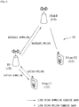
- FIG. 1 shows a relay node (RN) 120 and User Equipments (UEs) 131 and 132 located in an area of one base station (or eNodeB or eNB) 110 in a radio communication system 100.
- the RN 120 may transmit data received from the eNodeB 110 to the UE 132 located in an RN area and transmit data received from the UE 132 located in the RN area to the eNodeB 110.
- the RN 120 may expand a high data rate area, improve communication quality in a cell edge, and support provision of communication in a building or in an area other than a base station service area.
- FIG. 1 shows a relay node (RN) 120 and User Equipments (UEs) 131 and 132 located in an area of one base station (or eNodeB or eNB) 110 in a radio communication system 100.
- the RN 120 may transmit data received from the eNodeB 110 to the UE 132 located in an RN area and transmit data received from the UE 132 located
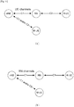
- a wireless link between the eNodeB and the RN is called a backhaul link.
- a link from the eNodeB to the RN is called a backhaul downlink and a link from the RN to the eNodeB is called a backhaul uplink.
- a wireless link between the RN and the UE is called an access link.
- a link from the RN to the UE is called an access downlink and a link from the UE to the RN is called an access uplink.
- a radio communication system in which the number of carriers configuring the uplink or the downlink is 1 and the bandwidth of the uplink and the bandwidth of the downlink are generally symmetrical to respect to each other may be provided based on a single carrier.
- ITU International Telecommunication Union
- bandwidth aggregation or spectrum aggregation technologies of physically aggregating a plurality of bands in a frequency domain so as to logically obtain the same effect as the use of a large band have been developed.
- the carrier aggregation technology may be also called multi-carrier technology.
- 3GPP Technical Report 36.912, V9.0.0 titled "3rd Generation Partnership Project; Technical Specification Group Radio Access Network; Feasibility study for Further Advancements for E-UTRA (LTE-Advanced) (Release 9)" relates to RAN aspects of technology components to be considered for the evolution of E-UTRA, e.g. to fulfil the requirements of IMT-Advanced.
- EP 2 418 784 A2 relates to a data transmission/receiving method and apparatus in a relay communication system.
- the data transmission/receiving method through a backhaul link between a base station and a relay node in a relay communication system comprises: composing a backhaul subframe including a control signal transmission period to which a control signal is allocated and a backhaul signal transmission period to which a backhaul signal is allocated and then allocating the backhaul signal; transmitting configuration information about the backhaul subframe, the information containing symbol position or size data of the backhaul signal transmission period, to the relay node through an upper layer signal; and transmitting the backhaul signal having been allocated through the backhaul subframe to the relay node.
- An object of the present invention devised to solve the problem lies on a method for efficiently transmitting and receiving a backhaul link signal, in a relay which operates on multiple carriers, in consideration of access link allocation.
- Another object of the present invention devised to solve the problem lies on a method for efficiently transmitting and receiving a signal on a backhaul link and an access link in a relay, if the relay performs a mixture of an in-band operation and an out-band operation on multiple carriers.
- a method according to claim 1 for transmitting and receiving a signal in a relay node operating on multiple carriers and a relay node according to claim 6 operating on multiple carriers are presented.
- a method for transmitting and receiving a signal in a relay node operating on multiple carriers including: receiving a control channel from a base station; determining the type of the control channel; determining an in-band operation mode or an out-band operation mode based on the determined type of the control channel; and transmitting and receiving the signal to and from at least one of the base station and a user equipment according to the determined operation mode, wherein the multiple carriers include one or more in-band component carriers and one or more out-band component carriers.
- the type of the control channel may be determined depending on whether the component carrier through which the control channel is received is the in-band component carrier or the out-band component carrier.
- the control channel may be received through a primary component carrier of the multiple carriers.
- the primary component carrier may be one of the one or more out-band component carriers.
- the control channel may include at least one of control information for a channel of the same type as the control channel and control information for a channel of a type different from that of the control channel.
- the channel type may be a UE-channel or an R-channel.
- a relay node operating on multiple carriers including: a reception module configured to receive a backhaul downlink from a base station and an access uplink from a user equipment; a transmission module configured to transmit a backhaul uplink to the base station and an access downlink to the user equipment; and a processor configured to control the reception module and the transmission module, wherein the processor is further configured to receive a control channel from the base station through the reception module, determine the type of the control channel, determine an in-band operation mode or an out-band operation mode based on the determined type of the control channel, and transmit and receive a signal to and from at least one of the base station and the user equipment according to the determined operation mode, and wherein the multiple carriers include one or more in-band component carriers and one or more out-band component carriers.
- the following embodiments are proposed by combining constituent components and characteristics of the present invention according to a predetermined format.
- the individual constituent components or characteristics should be considered to be optional factors on the condition that there is no additional remark. If required, the individual constituent components or characteristics may not be combined with other components or characteristics. Also, some constituent components and/or characteristics may be combined to implement the embodiments of the present invention.
- the order of operations to be disclosed in the embodiments of the present invention may be changed to another. Some components or characteristics of any embodiment may also be included in other embodiments, or may be replaced with those of the other embodiments as necessary.
- the embodiments of the present invention are disclosed on the basis of a data communication relationship between a base station and a terminal.
- the base station is used as a terminal node of a network via which the base station can directly communicate with the terminal.
- Specific operations to be conducted by the base station in the present invention may also be conducted by an upper node of the base station as necessary.
- Base Station may be replaced with a fixed station, Node-B, eNode-B (eNB), or an access point as necessary.
- relay may be replaced with a Relay Node (RN) or a Relay Station (RS).
- terminal may also be replaced with a User Equipment (UE), a Mobile Station (MS), a Mobile Subscriber Station (MSS) or a Subscriber Station (SS) as necessary.
- UE User Equipment
- MS Mobile Station
- MSS Mobile Subscriber Station
- SS Subscriber Station
- Exemplary embodiments of the present invention are supported by standard documents disclosed for at least one of wireless access systems including an Institute of Electrical and Electronics Engineers (IEEE) 802 system, a 3rd Generation Project Partnership (3GPP) system, a 3GPP Long Term Evolution (LTE) system, and a 3GPP2 system.
- IEEE Institute of Electrical and Electronics Engineers
- 3GPP 3rd Generation Project Partnership
- LTE 3GPP Long Term Evolution
- 3GPP2 3rd Generation Project 2
- All terminology used herein may be supported by at least one of the above-mentioned documents.
- the following embodiments of the present invention can be applied to a variety of wireless access technologies, for example, CDMA (Code Division Multiple Access), FDMA (Frequency Division Multiple Access), TDMA (Time Division Multiple Access), OFDMA (Orthogonal Frequency Division Multiple Access), SC-FDMA (Single Carrier Frequency Division Multiple Access), and the like.
- the CDMA may be embodied with wireless (or radio) technology such as UTRA (Universal Terrestrial Radio Access) or CDMA2000.
- the TDMA may be embodied with wireless (or radio) technology such as GSM (Global System for Mobile communications)/GPRS (General Packet Radio Service)/EDGE (Enhanced Data Rates for GSM Evolution).
- the OFDMA may be embodied with wireless (or radio) technology such as Institute of Electrical and Electronics Engineers (IEEE) 802.11 (Wi-Fi), IEEE 802.16 (WiMAX), IEEE 802-20, and E-UTRA (Evolved UTRA).
- IEEE Institute of Electrical and Electronics Engineers
- Wi-Fi Wi-Fi
- WiMAX WiMAX
- IEEE 802-20 E-UTRA
- the UTRA is a part of the UMTS (Universal Mobile Telecommunications System).
- the 3GPP (3rd Generation Partnership Project) LTE (long term evolution) is a part of the E-UMTS (Evolved UMTS), which uses E-UTRA.
- the 3GPP LTE employs the OFDMA in downlink and employs the SC-FDMA in uplink.
- the LTE-Advanced (LTE-A) is an evolved version of the 3GPP LTE.
- WiMAX can be explained by an IEEE 802.16e (WirelessMAN-OFDMA Reference System) and an advanced IEEE 802.16m (WirelessMAN-OFDMA Advanced System).
- IEEE 802.16e WirelessMAN-OFDMA Reference System
- advanced IEEE 802.16m WirelessMAN-OFDMA Advanced System
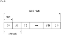
- FIG. 3 is a diagram showing a resource grid in a downlink slot.
- one downlink slot includes seven OFDM symbols in a time domain and one RB includes 12 subcarriers in a frequency domain in the figure, the present invention is not limited thereto.
- one slot includes 7 OFDM symbols.
- one slot includes 6 OFDM symbols.
- Each element on the resource grid is referred to as a resource element.
- One RB includes 12 ⁇ 7 resource elements.
- the number NDL of RBs included in the downlink slot is determined based on a downlink transmission bandwidth.
- the structure of the uplink slot may be equal to the structure of the downlink slot.
- FIG. 4 is a diagram showing the structure of a downlink subframe.
- a maximum of three OFDM symbols of a front portion of a first slot within one subframe corresponds to a control region to which a control channel is allocated.
- the remaining OFDM symbols correspond to a data region to which a Physical Downlink Shared Channel (PDSCH) is allocated.
- Examples of the downlink control channels used in the 3GPP LTE system include, for example, a Physical Control Format Indicator Channel (PCFICH), a Physical Downlink Control Channel (PDCCH), a Physical Hybrid automatic repeat request Indicator Channel (PHICH), etc.
- the PCFICH is transmitted at a first OFDM symbol of a subframe, and includes information about the number of OFDM symbols used to transmit the control channel in the subframe.
- the PHICH includes a HARQ ACK/NACK signal as a response of uplink transmission.
- the control information transmitted through the PDCCH is referred to as Downlink Control Information (DCI).
- DCI includes uplink or downlink scheduling information or an uplink transmit power control command for a certain UE group.
- the PDCCH may include resource allocation and transmission format of a Downlink Shared Channel (DL-SCH), resource allocation information of an Uplink Shared Channel (UL-SCH), paging information of a Paging Channel (PCH), system information on the DL-SCH, resource allocation of an higher layer control message such as a Random Access Response (RAR) transmitted on the PDSCH, a set of transmit power control commands for an individual UEs in a certain UE group, transmit power control information, activation of Voice over IP (VoIP), etc.
- a plurality of PDCCHs may be transmitted within the control region.
- the UE may monitor the plurality of PDCCHs.
- the PDCCHs are transmitted on an aggregation of one or several consecutive control channel elements (CCEs).
- CCEs control channel elements
- the CCE is a logical allocation unit used to provide the PDCCHs at a coding rate based on the state of a radio channel.
- the CCE corresponds to a plurality of resource element groups.
- the format of the PDCCH and the number of available bits are determined based on a correlation between the number of CCEs and the coding rate provided by the CCEs.
- the base station determines a PDCCH format according to a DCI to be transmitted to the UE, and attaches a Cyclic Redundancy Check (CRC) to control information.
- the CRC is masked with a Radio Network Temporary Identifier (RNTI) according to an owner or usage of the PDCCH.
- RNTI Radio Network Temporary Identifier
- a cell-RNTI (C-RNTI) of the UE may be masked to the CRC.
- a paging indicator identifier P-RNTI
- the PDCCH is for system information (more specifically, a system information block (SIB))
- SI-RNTI system information RNTI
- SI-RNTI system information RNTI
- RA-RNTI random access-RNTI
- FIG. 5 is a diagram showing the structure of an uplink frame.
- the uplink subframe may be divided into a control region and a data region in a frequency domain.
- a Physical Uplink Control Channel (PUCCH) including uplink control information is allocated to the control region.
- a Physical uplink Shared Channel (PUSCH) including user data is allocated to the data region.
- PUCCH Physical Uplink Control Channel
- PUSCH Physical uplink Shared Channel
- the PUCCH for one UE is allocated to a RB pair in a subframe. RBs belonging to the RB pair occupy different subcarriers with respect to two slots. Thus, the RB pair allocated to the PUCCH is "frequency-hopped" at a slot boundary.
- FIG. 6 is a diagram showing the configuration of a radio communication system having multiple antennas.
- N T the number of pieces of maximally transmittable information.
- s ⁇ may be expressed using a diagonal matrix P of the transmit powers as follows.
- the N T actually transmitted signals x 1 , x 2 , ⁇ , x N T are configured by applying a weight matrix w to the information vector s ⁇ with the adjusted transmit powers.
- the weight matrix w serves to appropriately distribute the transmitted information to each antenna according to a transport channel state, etc.
- x 1 , x 2 , ⁇ , s N T may be expressed by using the vector x as follows.
- w ij denotes a weight between an i-th transmission antenna and j-th information.
- w is also called a precoding matrix.
- channels are modeled in the MIMO radio communication system, the channels may be distinguished according to transmission/reception antenna indexes.
- a channel from the transmission antenna j to the reception antenna i is denoted by h ij .
- h ij it is noted that the indexes of the reception antennas precede the indexes of the transmission antennas in view of the order of indexes.
- FIG. 6(b) is a diagram showing channels from the N T transmission antennas to the reception antenna i.
- the channels may be combined and expressed in the form of a vector and a matrix.
- AWGN Additive White Gaussian Noise
- the AWGN n 1 , n 2 , ⁇ , n N R added to the N T transmission antennas may be expressed as follows.
- Math Figure 9 n n 1 , n 2 , ⁇ , n N R T
- the received signals may be expressed as follows.
- the number of rows and columns of the channel matrix H indicating the channel state is determined by the number of transmission and reception antennas.
- the number of rows of the channel matrix H is equal to the number N R of reception antennas and the number of columns thereof is equal to the number N T of transmission antennas. That is, the channel matrix H is an N R ⁇ N T matrix.
- the rank of the matrix is defined by the smaller of the number of rows or columns, which is independent from each other. Accordingly, the rank of the matrix is not greater than the number of rows or columns.
- the rank rank (H) of the channel matrix H is restricted as follows. Math Figure 11 rank H ⁇ min N T , N R
- the rank When the matrix is subjected to Eigen value decomposition, the rank may be defined by the number of Eigen values excluding 0. Similarly, when the matrix is subjected to singular value decomposition, the rank may be defined by the number of singular values excluding 0. Accordingly, the physical meaning of the rank in the channel matrix may be a maximum number of different transmittable information in a given channel.
- a signal may be distorted during transmission.
- distortion of the received signal should be corrected using channel information.
- a method of transmitting a signal, of which both the transmission side and the reception side are aware, and detecting channel information using a distortion degree when the signal is received through a channel is mainly used.
- the above signal is referred to as a pilot signal or a reference signal (RS).
- each transmission antenna has an individual RS.
- a downlink RS includes a Common RS (CRS) shared among all UEs in a cell and a Dedicated RS (DRS) for only a specific-UE. It is possible to provide information for channel estimation and demodulation using such RSs.
- CRS Common RS
- DRS Dedicated RS
- the reception side estimates the channel state from the CRS and feeds back an indicator associated with channel quality, such as a Channel Quality Indicator (CQI), a Precoding Matrix Index (PMI) and/or a Rank Indicator (RI), to the transmission side (eNodeB).
- CQI Channel Quality Indicator
- PMI Precoding Matrix Index
- RI Rank Indicator
- the CRS may be also called a cell-specific RS.
- an RS associated with the feedback of Channel State Information (CSI) such as CQI/PMI/RI may be separately defined as a CSI-RS.
- the DRS may be transmitted through REs if data demodulation on a PDSCH is necessary.
- the UE may receive the presence/absence of the DRS from a higher layer and receive information indicating that the DRS is valid only when the PDSCH is mapped.
- the DRS may be also called a UE-specific RS or a Demodulation RS (DMRS).
- FIG. 7 is a diagram showing a pattern of CRSs and DRSs mapped on a downlink RB defined in the existing 3GPP LTE system (e.g., Release-8).
- the downlink RB as a mapping unit of the RSs may be expressed in units of one subframe on a time domain ⁇ 12 subcarriers on a frequency domain. That is, on the time axis, one RB has a length of 14 OFDM symbols in case of the normal CP ( FIG. 7(a) ) and has a length of 12 OFDM symbols in case of the extended CP ( FIG. 7(b) ).
- FIG. 7 shows the locations of the RSs on the RB in the system in which the eNodeB supports four transmission antennas.
- Resource Elements (REs) denoted by “0", “1", “2” and “3” indicate the locations of the CRSs of the antenna port indexes 0, 1, 2 and 3, respectively.
- the RE denoted by "D” indicates the location of the DRS.
- the CRS is used to estimate the channel of a physical antenna and is distributed over the entire band as an RS which is able to be commonly received by all UEs located within a cell.
- the CRS may be used for CSI acquisition and data demodulation.
- the CRS is defined in various formats according to the antenna configuration of the transmission side (eNodeB).
- the 3GPP LTE e.g., Release-8) system supports various antenna configurations, and a downlink signal transmission side (eNodeB) has three antenna configurations such as a single antenna, two transmission antennas and four transmission antennas. If the eNodeB performs single-antenna transmission, RSs for a single antenna port are arranged. If the eNodeB performs two-antenna transmission, RSs for two antenna ports are arranged using a Time Division Multiplexing (TDM) and/or Frequency Division Multiplexing (FDM) scheme.
- TDM Time Division Multiplexing
- FDM Frequency Division Multiplexing
- the RSs for the two antenna ports are arranged in different time resources and/or different frequency resources so as to be distinguished from each other.
- RSs for four antenna ports are arranged using the TDM/FDM scheme.
- the channel information estimated by the downlink signal reception side (UE) through the CRSs may be used to demodulate data transmitted using a transmission scheme such as single antenna transmission, transmit diversity, closed-loop spatial multiplexing, open-loop spatial multiplexing, or Multi-User MIMO (MU-MIMO).
- a transmission scheme such as single antenna transmission, transmit diversity, closed-loop spatial multiplexing, open-loop spatial multiplexing, or Multi-User MIMO (MU-MIMO).
- the RSs are transmitted at the locations of the REs specified according to the RS pattern and any signal is not transmitted at the locations of the REs specified for another antenna port.
- Equation 12 The rule of mapping the CRSs to the RBs is defined by Equation 12.
- Equation 12 k denotes a subcarrier index, 1 denotes a symbol index, and p denotes an antenna port index.
- N symb DL denotes the number of OFDM symbols of one downlink slot
- N RB DL denotes the number of RBs allocated to the downlink
- n s denotes a slot index
- N ID cell denotes a cell ID. mod indicates a modulo operation.
- the location of the RS in the frequency domain depends on a value V shift . Since the value V shift depends on the cell ID, the location of the RS has a frequency shift value which varies according to the cell.
- the locations of the CRSs in the frequency domain may be shifted so as to be changed according to the cells.
- the RSs are located at an interval of three subcarriers, the RSs are arranged on 3k-th subcarriers in one cell and arranged on (3k+1)-th subcarriers in the other cell.
- the RSs are arranged at an interval of 6 REs (that is, interval of 6 subcarriers) in the frequency domain and are separated from REs, on which RSs allocated to another antenna port are arranged, by 3 REs in the frequency domain.
- power boosting is applied to the CRSs.
- the power boosting indicates that the RSs are transmitted using higher power by bringing (stealing) the powers of the REs except for the REs allocated for the RSs among the REs of one OFDM symbol.
- the time interval is differently defined according to the CP length.
- the RSs are located on symbol indexes 0 and 4 of the slot in case of the normal CP and are located on symbol indexes 0 and 3 of the slot in case of the extended CP. Only RSs for a maximum of two antenna ports are defined in one OFDM symbol.
- the RSs for the antenna ports 0 and 1 are located on the symbol indexes 0 and 4 (the symbol indexes 0 and 3 in case of the extended CP) of the slot and the RSs for the antenna ports 2 and 3 are located on the symbol index 1 of the slot.
- the frequency locations of the RSs for the antenna ports 2 and 3 in the frequency domain are exchanged with each other in a second slot.
- a system e.g., an LTE-A system having the extended antenna configuration may be designed.
- the extended antenna configuration may have, for example, eight transmission antennas.
- UEs which operate in the existing antenna configuration needs to be supported, that is, backward compatibility needs to be supported. Accordingly, it is necessary to support a RS pattern according to the existing antenna configuration and to design a new RS pattern for an additional antenna configuration. If CRSs for the new antenna ports are added to the system having the existing antenna configuration, RS overhead is rapidly increased and thus data transfer rate is reduced.
- LTE-A Advanced
- separate RSs CSI-RSs
- the DRS (or the UE-specific RS) is used to demodulate data.
- a precoding weight used for a specific UE upon multi-antenna transmission is also used in an RS without change so as to estimate an equivalent channel, in which a transfer channel and the precoding weight transmitted from each transmission antenna are combined, when the UE receives the RSs.
- the existing 3GPP LTE system (e.g., Release-8) supports four-transmission antenna transmission as a maximum and the DRS for Rank 1 beamforming is defined.
- the DRS for Rank 1 beamforming is also denoted by the RS for the antenna port index 5.
- the rule of the DRS mapped on the RBs is defined by Equations 13 and 14. Equation 13 is for the normal CP and Equation 14 is for the extended CP.
- DRS-based data demodulation is considered. That is, separately from the DRS (antenna port index 5) for Rank 1 beamforming defined in the existing 3GPP LTE (e.g., Release-8) system, DRSs for two or more layers may be defined in order to support data transmission through the added antenna.
- CoMP Cooperative Multi-Point
- CoMP transmission/reception technology may be referred to as co-MIMO, collaborative MIMO or network MIMO
- the CoMP technology can increase the performance of the UE located on a cell edge and increase average sector throughput.
- ICI Inter-Cell Interference
- FFR Fractional Frequency Reuse
- each point (eNodeB) of a CoMP unit may use data.
- the CoMP unit refers to a set of eNodeBs used in the CoMP scheme.
- the JP scheme may be classified into a joint transmission scheme and a dynamic cell selection scheme.
- the joint transmission scheme refers to a scheme for transmitting a PDSCH from a plurality of points (a part or the whole of the CoMP unit). That is, data transmitted to a single UE may be simultaneously transmitted from a plurality of transmission points. According to the joint transmission scheme, it is possible to coherently or non-coherently improve the quality of the received signals and to actively eliminate interference with another UE.
- coordinated multi-point reception refers to reception of a signal transmitted by coordination of a plurality of geographically separated points.
- the CoMP scheme applicable to the uplink may be classified into Joint Reception (JR) and Coordinated Scheduling/Beamforming (CS/CB).
- An SRS is used for enabling an eNodeB to measure channel quality so as to perform frequency-selective scheduling on the uplink and is not associated with uplink data and/or control information transmission.
- the present invention is not limited thereto and the SRS may be used for improved power control or supporting of various start-up functions of UEs which are not recently scheduled.
- the start-up functions may include, for example, initial Modulation and Coding Scheme (MCS), initial power control for data transmission, timing advance, and frequency-semi-selective scheduling (scheduling for selectively allocating frequency resources in a first slot of a subframe and pseudo-randomly hopping to another frequency in a second slot).
- MCS Modulation and Coding Scheme
- the subframe through which the SRS is transmitted by a certain UE within the cell is indicated by cell-specific broadcast signaling.
- 4-bit cell-specific "srsSubframeConfiguration" parameter indicates 15 possible configurations of the subframe through which the SRS can be transmitted within each radio frame. By such configurations, it is possible to provide adjustment flexibility of SRS overhead according to a network arrangement scenario.
- the remaining one (sixteenth) configuration of the parameters indicates the switch-off of the SRS transmission within the cell and is suitable for a serving cell for serving high-rate UEs.
- the SRS is always transmitted on a last SC-FDMA symbol of the configured subframe. Accordingly, the SRS and a Demodulation RS (DMRS) are located on different SC-FDMA symbols.
- DMRS Demodulation RS
- PUSCH data transmission is not allowed on the SC-FDMA symbol specified for SRS transmission and thus sounding overhead does not approximately exceed 7% even when it is highest (that is, even when SRS transmission symbols are present in all subframes).
- the RN may be considered for, for example, enlargement of high data rate coverage, improvement of group mobility, temporary network deployment, improvement of cell edge throughput and/or provision of network coverage to a new area.
- the RN 120 forwards data transmitted or received between the eNodeB 110 and the UE 131, two different links (backhaul link and access link) are applied to the respective carrier frequency bands having different attributes.
- the eNodeB 110 may include a donor cell.
- the RN 120 is wirelessly connected to a radio access network through the donor cell 110.
- the backhaul link between the eNodeB 110 and the RN 120 may be represented by a backhaul downlink if downlink frequency bands or downlink subframe resources are used, and may be represented by a backhaul uplink if uplink frequency bands or uplink subframe resources are used.
- the frequency band is resource allocated in a Frequency Division Duplex (FDD) mode and the subframe is resource allocated in a Time Division Duplex (TDD) mode.
- the access link between the RN 120 and the UE(s) 131 may be represented by an access downlink if downlink frequency bands or downlink subframe resources are used, and may be represented by an access uplink if uplink frequency bands or uplink subframe resources are used.
- FIG. 1 shows the setting of the backhaul uplink/downlink and the access uplink/downlink of the FDD-mode RN.
- the eNodeB must have functions such as uplink reception and downlink transmission and the UE must have functions such as uplink transmission and downlink reception.
- the RN must have all functions such as backhaul uplink transmission to the eNodeB, access uplink reception from the UE, the backhaul downlink reception from the eNodeB and access downlink transmission to the UE.
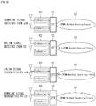
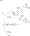
- FIG. 9 is a diagram showing an example of implementing transmission and reception functions of a FDD-mode RN.
- the reception function of the RN will now be conceptually described.
- a downlink signal received from the eNodeB is forwarded to a Fast Fourier Transform (FFT) module 912 through a duplexer 911 and is subjected to an OFDMA baseband reception process 913.
- An uplink signal received from the UE is forwarded to a FFT module 922 through a duplexer 921 and is subjected to a Discrete Fourier Transform-spread-OFDMA (DFT-s-OFDMA) baseband reception process 923.
- FFT Fast Fourier Transform
- DFT-s-OFDMA Discrete Fourier Transform-spread-OFDMA
- duplexers shown as functioning in one direction may be implemented by one bidirectional duplexer.
- the duplexer 911 and the duplexer 931 may be implemented by one bidirectional duplexer and the duplexer 921 and the duplexer 941 may be implemented by one bidirectional duplexer.
- the bidirectional duplexer may branch into the IFFT module associated with the transmission and reception on a specific carrier frequency band and the baseband process module line.
- the case where the backhaul link operates in the same frequency band as the access link is referred to as "in-band” and the case where the backhaul link and the access link operate in different frequency bands is referred to as "out-band”.
- in-band the case where the backhaul link operates in the same frequency band as the access link
- out-band the case where the backhaul link and the access link operate in different frequency bands.
- a UE which operates according to the existing LTE system e.g., Release-8
- a legacy UE must be able to be connected to the donor cell.
- the RN may be classified into a transparent RN or a non-transparent RN depending on whether or not the UE recognizes the RN.
- transparent indicates that the UE cannot recognize whether communication with the network is performed through the RN and the term “non-transparent” indicates that the UE recognizes whether communication with the network is performed through the RN.
- the RN may be classified into a RN configured as a part of the donor cell or a RN for controlling the cell.
- the RN configured as the part of the donor cell may have a RN ID, but does not have its cell identity.
- RRM Radio Resource Management
- the RN is configured as the part of the donor cell.
- such an RN can support a legacy UE.
- examples of such an RN include various types of relays such as smart repeaters, decode-and-forward relays, L2 (second layer) relays and Type-2 relays.
- the Type-1 relay is an in-band relay for controlling a plurality of cells, which appears to be different from the donor cell, from the viewpoint of the UE.
- the plurality of cells has respective physical cell IDs (defined in the LTE Release-8) and the RN may transmit its synchronization channel, RSs, etc.
- the UE may directly receive scheduling information and HARQ feedback from the RN and transmit its control channel (Scheduling Request (SR), CQI, ACK/ NACK, etc.) to the RN.
- SR Service Request
- CQI CQI
- ACK/ NACK etc.
- a legacy UE (a UE which operates according to the LTE Release-8 system) regards the Type-1 relay as a legacy eNodeB (an eNodeB which operates according to the LTE Release-8 system). That is, the Type-1 relay has backward compatibility.
- the UEs which operates according to the LTE-A system regard the Type-1 relay as an eNodeB different from the legacy eNode
- the Type-la relay has the same characteristics as the above-described Type-1 relay except that it operates as an out-band relay.
- the Type-1a relay may be configured so as to minimize or eliminate an influence of the operation thereof on an L1 (first layer) operation.
- the Type-2 relay is an in-band relay and does not have a separate physical cell ID. Thus, a new cell is not established.
- the Type-2 relay is transparent to the legacy UE and the legacy UE does not recognize the presence of the Type-2 relay.
- the Type-2 relay can transmit a PDSCH, but does not transmit at least a CRS and a PDCCH.
- resource partitioning In order to enable the RN to operate as the in-band relay, some resources in a time-frequency space must be reserved for the backhaul link so as not to be used for the access link. This is called resource partitioning.
- the backhaul downlink and the access downlink may be multiplexed on one carrier frequency using a Time Division Multiplexing (TDM) scheme (that is, only one of the backhaul downlink or the access downlink is activated in a specific time).
- TDM Time Division Multiplexing
- the backhaul uplink and the access uplink may be multiplexed on one carrier frequency using the TDM scheme (that is, only one of the backhaul uplink or the access uplink is activated in a specific time).
- the multiplexing of the backhaul link using a FDD scheme indicates that backhaul downlink transmission is performed in a downlink frequency band and the backhaul uplink transmission is performed in an uplink frequency band.
- the multiplexing of the backhaul link using the TDD scheme indicates that the backhaul downlink transmission is performed in a downlink subframe of the eNodeB and the RN and the backhaul uplink transmission is performed in an uplink subframe of the eNodeB and the RN.
- a first subframe 1010 is a general subframe, in which a downlink (that is, access downlink) control signal and data is transmitted from the RN to the UE
- a second subframe 1020 is an MBSFN subframe, in which a control signal is transmitted from the RN to the UE in a control region 1021 of the downlink subframe, but any signal is not transmitted from the RN to the UE in the remaining region 1022 of the downlink subframe.
- N 1, 2 or 3 OFDM symbol intervals of the subframe
- the PDCCH is transmitted from the RN to the UE in the control region 1021 of the second subframe, it is possible to provide backward compatibility to the legacy UE served by the RN. While any signal is not transmitted from the RN to the UE in the remaining region 1022 of the second subframe, the RN may receive the signal transmitted from the eNodeB. Accordingly, the resource partitioning disables the in-band RN to simultaneously perform the access downlink transmission and the backhaul downlink reception.
- the control region 1021 of the second subframe may be a RN non-hearing interval.
- the RN non-hearing interval refers to an interval in which the RN does not receive a backhaul downlink signal and transmits an access downlink signal. This interval may be set to 1, 2 or 3 OFDM lengths as described above.
- the RN performs the access downlink transmission to the UE in the RN non-hearing interval 1021 and performs the backhaul downlink reception from the eNodeB in the remaining region 1022.
- a guard time to switch the RN from the transmission mode to the reception mode in a first portion of the backhaul downlink reception region 1022.
- a guard time to switch the RN from the reception mode to the transmission mode may be set.
- the length of the guard time may be set to values of the time domain, for example, values of k (k ⁇ 1) time samples Ts or one or more OFDM symbol lengths.
- the guard time of a last portion of the subframes may not be defined or set.
- Such a guard time may be defined only in the frequency domain set for the transmission of the backhaul downlink subframe, in order to maintain backward compatibility (the legacy UE cannot be supported if the guard time is set in the access downlink interval).
- the RN can receive a PDCCH and a PDSCH from the eNodeB in the backhaul downlink reception interval 1022 except for the guard time.
- PDCCH and the PDSCH are physical channels dedicated for RN and thus may be represented by a R-PDCCH (Relay-PDCCH) and a R-PDSCH (Relay-PDSCH).
- a mode (that is, a plurality of component carriers (CCs)) there are a mode (mode A) in which the backhaul link and the access link are present in different frequency bands and a mode (mode B) in which the backhaul link and the access link are present in the same frequency band.
- mode A the backhaul link and the access link are present in different frequency bands
- mode B the backhaul link and the access link are present in the same frequency band.
- the RN cannot simultaneously perform the transmission and reception within one frequency band due to interference between the transmitted and received signals (that is, a half-duplex operation is performed in one frequency band).
- two different frequency bands are sufficiently separated and the RN can transmit a signal in one band and, at the same time, receive a signal in another band (that is, a full-duplex operation is performed over the two different frequency bands).
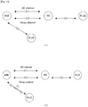
- FIG. 11 is a diagram showing a relay operation on two frequency bands C1 and C2.
- C1 denotes a first CC and C2 denotes a second CC.
- FIG. 11(a) shows the relay operation in the mode A
- FIG. 11(b) shows the relay operation in the mode B
- the RN may communicate with the eNB and the UE (R-UE) on C1 and C2, respectively. Since the backhaul link and the access link are defined on different frequency bands (C1 and C2) (that is, out-band), the time-domain separation between the backhaul link and the access link is unnecessary, and all channels designed for communication between the eNB and the UE (which are called UE-channels and include a PDCCH, a PDSCH, a PUCCH and a PUSCH) are used for the backhaul link.
- C1 and C2 that is, out-band
- the eNB since the eNB does not need to consider the UE (R-UE) in the relay coverage in the physical channel structure with respect to the RN using the out-band frequency band, the eNB regards the RN as a general UE and can perform communication through the same physical channel structure as the existing UE (macro-UE).
- the channel (UE-channel) designed for the existing UE may not be used without change and the channel separately designed for the RN of the mode B (which is called an R-channel and include an R-PDCCH, an R-PDSCH, an R-PUCCH and an R-PUSCH) may be used for the backhaul link.
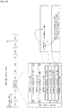
- FIG. 12 is a diagram showing an example of a subframe channel structure allocated to a downlink backhaul link in the mode B.
- First two or three OFDM symbols of a certain downlink subframe e.g., a subframe index #3
- the guard time (GT) to switch the RN between the transmission mode and the reception mode is allocated.
- the backhaul link signal transmitted to the RN includes two different physical channels (R-PDCCH and R-PDSCH).
- the R-PDCCH includes control information and the R-PDSCH includes data.
- Primary backhaul resources include the R-PDCCH, and the R-PDCCH and the R-PDSCH may be multiplexed in the primary backhaul resources using a TDM scheme.
- Secondary backhaul resources do not include an R-PDCCH, and the R-PDCCH of the primary backhaul resources and the R-PDSCH of the secondary backhaul resources may be multiplexed using a FDM scheme.
- the multiplexing scheme of the RN channels is exemplary and is not limited to the above scheme. That is, although the R-PDCCH and the R-PDSCH are multiplexed using both the TDM and FDM schemes in FIG. 12 , the scheme is not limited thereto and the multiplexing may be performed using the TDM scheme or the FDM scheme.
- the R-PDCCH and the R-PDSCH may be multiplexed using only the FDM scheme. That is, in the OFDM symbols of the primary backhaul resources, the R-PDSCH is not transmitted, but only the R-PDCCH is transmitted.
- the R-PDCCH of the primary backhaul resources and the R-PDSCH of the secondary backhaul resources may be multiplexed using the FDM scheme.
- the multiplexing scheme of the R-channels may be semi-statically configured by higher layer signaling or dynamically configured by L1/L2 control signals.
- FIG. 13 is a diagram showing an example of the configuration of a backhaul link and an access link, to which the present invention is applied. As shown in FIG. 13 , it is assumed that the RN configures the backhaul link with the eNB using two frequency bands (C1 and C2) and configures the access link with the R-UE using one frequency band (C2).
- C1 and C2 two frequency bands
- C2 one frequency band
- the backhaul link through C1 may be referred to as a relay out-band operation.
- the backhaul link between the eNB and the RN is allocated to the frequency band C1 and the access link between the RN and the R-UE is allocated to the frequency band C2. That is, since the backhaul link and the access link are allocated to different frequency bands, it is referred to as out-band.
- the RN may operate in the mode A on C1.
- the backhaul link through C2 may be referred to as a relay in-band operation. That is, since both the backhaul link and the access link are allocated to the same frequency band C2, it is referred to as in-band. In this case, the RN may operate in the mode B on C2.
- C1 is solely used for the backhaul link and the backhaul link and the access link are multiplexed on C2 using the TDM scheme is because more resources are to be allocated to the backhaul link in consideration that, if the resources of the backhaul link is insufficient, a bottleneck phenomenon occurs and thus the system performance may deteriorate.
- the center frequencies of the frequency bands (CCs) C1 and C2 are different, since there is a difference between in cell coverage between the respective frequency bands and propagation delay may be differently generated, it may not be efficient that both C1 and C2 are used for the access link for the R-UE.
- the transmitter and the receiver for the transmission and reception between the RN and the R-UE needs to use expensive parts similar to the transmitter and the receiver of the existing eNB, but the transmitter and the receiver for the transmission and reception between the RN and the eNB may use cheap parts similar to the transmitter and the receiver of the existing UE. Accordingly, cost consumed for adding the transmitter and the receiver for the in-band operation in a separate frequency band to the configuration of the RN for the in-band operation in a specific frequency band is high, but cost consumed for adding the transmitter and the receiver for the out-band operation in a separate frequency band is relatively low. Accordingly, in consideration of the above-described various viewpoints, for example, if the RN uses two frequency bands (CCs), it is preferable that the in-band operation is performed in one frequency band and the out-band operation is performed in the other frequency band.
- CCs frequency bands
- the eNB may communicate with the M-UE through the frequency band C2.
- the backhaul link configured on the frequency C1 among the backhaul links between the eNB and the RN may be configured on the frequency band different from that of the link between the eNB and the M-UE configured on the frequency band C2.
- the RN since the RN can transmit and receive the backhaul signal using C1 corresponding to the separate resources other than the resources C2 used for the M-UE, it is advantageous in that the amount of resources allocated to the M-UE is preserved.
- the eNB may communicate with the M-UE through the frequency band C1 (or C1 and C2).
- the backhaul link configured on the frequency band C1 among the backhaul links between the eNB and the RN may be configured on the same frequency band as the link between the eNB and the M-UE configured on the frequency band C1.
- the backhaul link of the RN may maximally share the resources with the M-UE and an operation such as multi-user MIMO (MU-MIMO) between the M-UE and the RN can be smoothly performed.
- MU-MIMO multi-user MIMO
- channels on respective frequency bands are controlled by a control channel on the same frequency band.
- the PDSCH/PUSCH/PUCCH on C1 may be controlled by the PDCCH on C1
- the R-PDSCH/R-PUSCH/R-PUCCH on C2 may be controlled by the R-PDCCH on C2.
- the control information included in the PDCCH or the R-PDCCH may include information about scheduling, resource allocation, power control, etc.
- Such a scheme is equal to the existing physical channel control configuration and thus may be simply implemented. However, overhead associated with blind decoding of the control channel may be increased.
- channels on a plurality of frequency bands are controlled by a control channel on the frequency band operating in the mode B (that is, in-band).
- the PDSCH/PUSCH/PUCCH on C1 and the R-PDSCH/R-PUSCH/R-PUCCH on C2 may be controlled by the R-PDCCH on C2.
- Such a scheme is not efficient in the resource usage because the R-PDCCH is separately defined in the data region of the subframe, but may be efficient when it is difficult to perform reliable control channel transmission on C1.
- this scheme may be applied when C1 is an extended CC without the PDCCH.
- this scheme may be applied when fractional frequency reuse is applied and transmit power on C1 is lower than the transmit power on C2.
- the eNB may inform the RN of the location of the control channel which must be monitored by the RN through higher layer signaling (e.g., RRC signaling).
- the RN may change the control channel to be monitored according to signaling from the eNB.
- the cross-channel control capability refers to capability to provide control information of a different type of channel, and, in the present embodiment, indicates that the control channel of the UE-channel provides control information of the R-channel or the control channel of the R-channel provides control information of the UE-channel. That is, the PDCCH on C1 may have control capability of the R-channels in the scheme 2, and the R-PDCCH on C2 may have control capability of UE-channels in the scheme 3.
- the control channel may include an indicator indicating the type (UE-channel or R-channel) of the controlled channel to the RN.
- each of the frequency bands C1 and C2 may be a FDD band having an uplink CC and a downlink CC.
- each of the frequency bands C1 and C2 may be a TDD band in which the uplink transmission and the downlink transmission are identified on one CC in the time domain.
- the out-band backhaul link CC may be set to a primary CC (which may be also called an "anchor CC") of the backhaul link between the eNB and the RN.
- the primary CC refers to a CC on which uplink/ downlink control information is transmitted.
- scheduling control information for uplink/downlink transmission on the out-band CC C1 may be transmitted on the CC C1 and scheduling control information for uplink/downlink transmission on the in-band CC C2 may be transmitted on C1, that is, cross-carrier scheduling may be performed.
- the cross-carrier scheduling in downlink refers to the case where control information (DL allocation PDCCH) for scheduling PDSCH transmission on the first downlink CC (first DL CC) is transmitted not on the first DLCC, but on another DL CC (e.g., a second DL CC).
- the cross-carrier scheduling in uplink refers to the case where control information (UL grant PDCCH) for scheduling PUSCH transmission on a first UL CC is transmitted not on a DL CC set to be linked with the first UL CC (e.g., a first DL CC), but on another DL CC (e.g., a second DL CC).
- control information UL grant PDCCH
- one out-band backhaul link CC C1 may be used only for control signal transmission/reception, one or more in-band backhaul link CC(s) may be used for data signal transmission/reception.
- one or more in-band backhaul link CC(s) may be cross-carrier scheduled by one out-band backhaul link CC C1.
- a determination as to which of CCs is used for control signal transmission or data transmission may be made according to the following criterion.
- the RN operates on an in-band CC and the primary CC is an in-band CC, since an opportunity to transmit the R-PDCCH/R-PUCCH is given to only some subframes to which the access link subframe is not allocated, the continuity of the control channel transmission may not be guaranteed.
- the allocation of a pair of subframes (or the allocation of associated subframes) may be considered in the allocation of the downlink and uplink backhaul subframe.
- the allocation of the pair of subframes may be set according to the relationship between the uplink and downlink subframes in a scheduling operation or a HARQ operation.
- an uplink subframe e.g., a subframe index n
- a specific downlink subframe e.g., a subframe index n-4
- an R-PDCCH including an uplink grant message used to schedule uplink transmission of a specific subframe needs to be transmitted prior to a specific number of subframes which corresponds to 4 ms (four subframes).
- a downlink subframe e.g., a subframe index m
- a specific uplink subframe e.g., a subframe index m+4 needs to be allocated to backhaul uplink transmission.
- a scheduling operation or HARQ operation with another period may be separately configured.
- the HARQ operation may be set such that, after backhaul uplink transmission is performed, an ACK/NACK signal thereof is not transmitted through a backhaul downlink PHICH, that is, the RN does not expect the ACK/NACK signal for the backhaul uplink transmission.
- the introduction of the separate scheduling operation or HARQ operation may lead to complexity and overhead of the transmission/reception operation.
- the backhaul subframe allocation scheme may be changed according to the operation mode on the primary CC of the RN.
- the uplink and downlink subframe allocation may be configured in a paired (or associated) manner. For example, if the downlink backhaul subframe is allocated by a bitmap message, the uplink backhaul subframe allocation may be determined based on a predetermined rule according to the downlink backhaul subframe allocation. The predetermined rule may be determined according to the scheduling operation or the HARQ operation as described above.
- a subframe n may be allocated to an uplink backhaul subframe according to the scheduling operation, and a subframe n-4 may be allocated to the downlink backhaul subframe in order to transmit the UL grant for the uplink transmission of the subframe n.
- a subframe m may be allocated to the downlink backhaul subframe, and a subframe m+4 may be allocated to the uplink backhaul subframe according to the HARQ ACK/NACK operation in order to transmit the ACK/NACK signal for the downlink transmission of the subframe m.
- the backhaul link transmission/reception operation and the type (UE-channel or R-channel) of the control channel indicating the operation may be connected.
- the backhaul link transmission/reception operation may include various features such as ACK/NACK, retransmission, or UL grant.
- the backhaul link transmission/reception operation may be different on the out-band CC and the in-band CC.
- non-adaptive uplink retransmission based on the PHICH is possible in the out-band CC.
- the downlink physical channel for the downlink ACK/NACK transmission is not provided on the in-band CC, non-adaptive uplink retransmission may be impossible in the in-band CC.
- synchronous uplink retransmission with a period of 8 ms is used in the out-band CC
- synchronous uplink retransmission with another period of 10 ms or asynchronous uplink retransmission may be used in the in-band CC such that the operation is performed according to the irregular backhaul subframe configuration.
- the operation mode of the backhaul link CC may be determined according to the operation mode of the CC (that is, the type (UE-channel or R-channel) of the control channel indicating the backhaul link transmission/reception).
- the RN may receive the control channel from the eNB in step S1610.
- step S1620 RN may determine the type of the received control channel, that is, whether the received control channel is a UE-channel (e.g., PDCCH) or an R-channel (e.g., an R-PDCCH). If the control channel is the UE-channel in step S1620, step S1630 is performed and, if the control channel is the R-channel, step S1640 is performed. If the received control channel is the UE-channel (PDCCH), the RN may operate according to the out-band operation mode in step S1630.
- UE-channel e.g., PDCCH
- R-PDCCH e.g., an R-PDCCH
- the RN may operate according to the in-band operation mode in step S1640. Thereafter, the RN may receive a new control channel in step S1610 and perform the in-band or out-band operation according to the type of the received control channel.
- the backhaul link transmission/reception procedure indicated by the PDCCH may be performed according to the operation on the out-band CC.
- the PDCCH that is, the UE-channel
- the backhaul link transmission/reception procedure indicated by the PDCCH may be performed according to the operation on the out-band CC.
- non-adaptive retransmission based on the PHICH is possible and synchronous retransmission with a period of 8 ms is possible.
- the backhaul link transmission/reception procedure indicated by the R-PDCCH may be performed according to the operation on the in-band CC.
- DL ACK/NACK may not be present (that is, after the RN perform backhaul uplink transmission, the eNB does not transmit ACK/NACK through the backhaul downlink PHICH), synchronous retransmission with a period (e.g., 10 ms) other than a period of 8 ms may be performed or asynchronous retransmission is possible.
- the backhaul link transmission/reception operation mode of the RN is not determined according to the relay operation mode on the CC on which data is transmitted and received (that is, the backhaul link transmission/reception operation mode of the RN does not depend on whether the CC on which data is transmitted and received is an out-band or in-band).
- the number of CCs (or frequency bands) allocated to the RN is two in the above-described embodiments of the present invention, the number of CCs is not limited thereto. That is, similar to the above-described principle of the present invention, even when two or more CCs are allocated to the RN, cross-channel scheduling (scheduling for different types of channels) may be applied, one of out-band CCs may be set to a primary CC, and an out-band operation or an in-band operation may be performed according to the type (UE-channel or R-channel) of the received control channel.
- FIG. 17 is a diagram showing the configuration of a radio communication system including a RN device, an eNodeB device, a UE device according to an exemplary embodiment of the present invention.
- the detailed configuration of the RN device 1710 will be described with reference to FIG. 17 .
- the RN 1710 may transmit and receive control information and/or data through a backhaul uplink and a backhaul downlink. In addition, the RN 1710 may transmit and receive control information and/or data to or from a UE 1730 through an access downlink and an access uplink.
- the RN 1710 may include a reception module 1711, a transmission module 1712, a processor 1713, a memory 1714, and a plurality of antennas 1715.
- This RN supports a Multi-Input Multi-Output (MIMO) scheme because the plurality of antennas is used.
- MIMO Multi-Input Multi-Output
- the reception module 1711 may receive a variety of signals, data and information on the backhaul downlink from the eNodeB and the access uplink from the UE.
- the transmission module 1712 may transmit a variety of signals, data and information on the backhaul uplink to the eNodeB and the access downlink to the UE.
- the processor 1713 may control the overall operation of the RN 1710. In particular, the process 1713 may control the transmission and the reception of the variety of signals, data and information through the reception module 1711 and the transmission module 1712.
- the RN 1710 supports the transmission and reception through multiple carriers. That is, the RN 1710 may communicate with the eNodeB 1720 and the UE 1730 through one or more CCs.
- the multiple carriers associated with the relay operation may include one or more in-band CCs and one or more out-band CCs. That is, the RN may be an in-band and out-band hybrid RN.
- the processor 1713 of the RN 1710 may receive the control channel from the eNodeB through the reception module 1711 and determine the type of the received control channel.
- the type of the control channel may be determined depending on whether the CC on which the control channel is received is an in-band CC or an out-band CC.
- the channel type may be one of the UE-channel or the R-channel.
- the control channel may be received through a primary CC.
- the primary CC may be set to one of out-band CCs.
- the control channel may include at least one of control information for the channel of the same type of the control channel and control information for the channel of the type different from that of the control channel. That is, cross-channel scheduling may be performed by the control channel.
- the processor 1713 of the RN 1710 may determine an in-band operation mode or an out-band operation mode based on the determined type of the control channel, and transmit and receive signals to or from at least one of the eNodeB and the UE through the reception module 1711 and the transmission module 1712 according to the determined operation mode.
- the in-band operation mode refers to an operation mode in which the backhaul link and the access link are set on the same CC
- the out-band operation mode refers to an operation mode in which the backhaul link and the access link are set on different CCs.
- the processor 1713 of the RN 1710 performs a function for calculating information received by the RN and information to be transmitted to an external device, and the memory 1714 may store the calculated information and may be replaced with a component such as a buffer (not shown).
- the present invention can be implemented with application specific integrated circuits (ASICs), Digital signal processors (DSPs), digital signal processing devices (DSPDs), programmable logic devices (PLDs), field programmable gate arrays (FPGAs), a processor, a controller, a microcontroller, a microprocessor, etc.
- ASICs application specific integrated circuits
- DSPs Digital signal processors
- DSPDs digital signal processing devices
- PLDs programmable logic devices
- FPGAs field programmable gate arrays
- processor a processor
- controller a microcontroller
- microprocessor a microprocessor
- the present invention can be implemented in the form of a variety of formats, for example, modules, procedures, functions, etc.
- the software codes may be stored in a memory unit so that it can be driven by a processor.
- the memory unit is located inside or outside of the processor, so that it can communicate with the aforementioned processor via a variety of well-known parts.
- the embodiments of the present invention are applicable to various mobile communication systems.
Landscapes
- Engineering & Computer Science (AREA)
- Signal Processing (AREA)
- Computer Networks & Wireless Communication (AREA)
- Power Engineering (AREA)
- Quality & Reliability (AREA)
- Mobile Radio Communication Systems (AREA)
Claims (6)
- Verfahren zum Senden und Empfangen eines Signals in einem Relaisknoten (1710), der auf mehreren Trägern arbeitet, wobei das Verfahren umfasst:Empfangen (S1610) eines Steuerkanals von einer Basisstation (1720);Ermitteln (S1620) eines Typs des Steuerkanals;wobei der Typ des Steuerkanals abhängig davon ermittelt (S1620) wird, ob der Komponententräger, über den der Steuerkanal empfangen (S1610) wird, der In-band-Komponententräger oder der Out-of-band-Komponententräger ist,Ermitteln (S1630, S1640) eines In-band-Betriebsmodus oder eines Out-of-band-Betriebsmodus, wenn der Relaisknoten (1710) eine Mischung des In-band-Betriebsmodus und des Out-of-band-Betriebsmodus auf mehreren Trägern durchführt, auf Basis des ermittelten (S1620) Typs des Steuerkanals; undSenden des Signals an zumindest eines der Basisstation (1720) und eines Endgeräts, UE, (1730) und Empfangen desselben davon gemäß dem ermittelten (S1630, S1640) Betriebsmodus,wobei die mehreren Träger einen oder mehrere In-band-Komponententräger und einen oder mehrere Out-of-band-Komponententräger umfassen,wobei der Steuerkanal ein Physical Downlink Control Channel, PDCCH, ist, wenn der Steuerkanal über den Out-of-band-Komponententräger empfangen (S1610) wird, undwobei der Steuerkanal ein Relais-PDCCH, R-PDCCH, ist, wenn der Steuerkanal über den In-band-Komponententräger empfangen (S1610) wird.
- Verfahren nach Anspruch 1, wobei der Steuerkanal über einen primären Komponententräger der mehreren Träger empfangen (S1610) wird.
- Verfahren nach Anspruch 2, wobei der primäre Komponententräger einer des einen oder der mehreren Out-of-band-Komponententräger ist.
- Verfahren nach Anspruch 1, wobei der Steuerkanal zumindest eines von Steuerinformation für einen Kanal des gleichen Typs wie der Steuerkanal und Steuerinformation für einen Kanal eines anderen Typs als der Steuerkanal umfasst.
- Verfahren nach Anspruch 1, wobei:der In-band-Betriebsmodus ein Betriebsmodus ist, bei dem eine Backhaul-Verbindung zwischen der Basisstation (1720) und dem Relaisknoten (1710) und eine Access-Verbindung zwischen dem Relaisknoten (1710) und dem UE (1730) auf dem gleichen Komponententräger eingerichtet sind, undder Out-of-band-Betriebsmodus ein Betriebsmodus ist, bei dem der Backhaul-Verbindung zwischen der Basisstation (1720) und dem Relaisknoten (1710) und die Access-Verbindung zwischen dem Relaisknoten (1710) und dem UE (1730) auf unterschiedlichen Komponententrägern eingerichtet sind
- Relaisknoten (1710), der auf mehreren Trägern arbeitet, wobei der Relaisknoten (1710) umfasst:ein Empfangsmodul (1711), das so konfiguriert ist, dass es eine Backhaul-Abwärtsstrecke von einer Basisstation (1720) und eine Access-Aufwärtsstrecke von einem Endgerät (1730) empfängt;ein Sendemodul (1712), das so konfiguriert ist, dass es eine Backhaul-Aufwärtsstrecke an die Basisstation (1720) sendet und eine Access-Abwärtsstrecke an das Endgerät (1730) sendet; undeinen Prozessor (1713), der so konfiguriert ist, dass er das Empfangsmodul (1711) und das Sendemodul (1712) steuert,wobei der Prozessor (1713) ferner konfiguriert ist zum:Empfangen (S1610) eines Steuerkanals von der Basisstation (1720) über das Empfangsmodul (1711),Ermitteln (S1620) eines Typs des Steuerkanals,wobei der Typ des Steuerkanals abhängig davon ermittelt (S1620) wird, ob der Komponententräger, über den der Steuerkanal empfangen (S1610) wird, der In-band-Komponententräger oder der Out-of-band-Komponententräger ist,Ermitteln (S1630, S1640) eines In-band-Betriebsmodus oder eines Out-of-band-Betriebsmodus, wenn der Relaisknoten (1710) eine Mischung des In-band-Betriebsmodus und des Out-of-band-Betriebsmodus auf mehreren Trägern durchführt, auf Basis des ermittelten (S1620) Typs des Steuerkanals, undSenden eines Signals an zumindest eines der Basisstation (1720) und eines Endgeräts (1730) und Empfangen desselben davon gemäß dem ermittelten (S1630, S1640) Betriebsmodus, undwobei die mehreren Träger einen oder mehrere In-band-Komponententräger und einen oder mehrere Out-of-band-Komponententräger umfassen,wobei der Steuerkanal ein Physical Downlink Control Channel, PDCCH, ist, wenn der Steuerkanal über den Out-of-band-Komponententräger empfangen (S1610) wird, undwobei der Steuerkanal ein Relais-PDCCH, R-PDCCH, ist, wenn der Steuerkanal über den In-band-Komponententräger empfangen (S1610) wird.
Applications Claiming Priority (3)
| Application Number | Priority Date | Filing Date | Title |
|---|---|---|---|
| US25582609P | 2009-10-28 | 2009-10-28 | |
| US31309110P | 2010-03-11 | 2010-03-11 | |
| PCT/KR2010/007369 WO2011052964A2 (en) | 2009-10-28 | 2010-10-26 | Method for transmitting and receiving signal of relay in radio communication system supporting multiple carriers |
Publications (3)
| Publication Number | Publication Date |
|---|---|
| EP2494706A2 EP2494706A2 (de) | 2012-09-05 |
| EP2494706A4 EP2494706A4 (de) | 2016-06-22 |
| EP2494706B1 true EP2494706B1 (de) | 2018-10-03 |
Family
ID=43922800
Family Applications (1)
| Application Number | Title | Priority Date | Filing Date |
|---|---|---|---|
| EP10827048.9A Not-in-force EP2494706B1 (de) | 2009-10-28 | 2010-10-26 | Verfahren zum übertragen und empfangen eines signals von einer relaisstation in einem funkkommunikationssystem mit mehreren trägern |
Country Status (4)
| Country | Link |
|---|---|
| US (1) | US8737289B2 (de) |
| EP (1) | EP2494706B1 (de) |
| KR (1) | KR101789630B1 (de) |
| WO (1) | WO2011052964A2 (de) |
Families Citing this family (37)
| Publication number | Priority date | Publication date | Assignee | Title |
|---|---|---|---|---|
| KR101603338B1 (ko) * | 2008-08-11 | 2016-03-15 | 엘지전자 주식회사 | 무선 통신 시스템에서 정보 전송 방법 및 장치 |
| US9681423B2 (en) * | 2008-10-29 | 2017-06-13 | Lg Electronics Inc. | Method for efficiently transmitting physical channel in multi-carrier aggregation state to support broadband |
| US8767641B2 (en) * | 2009-11-16 | 2014-07-01 | Texas Instruments Incorporated | Carrier indication in a bandwidth aggregated wireless communications systems |
| WO2011094926A1 (en) * | 2010-02-02 | 2011-08-11 | Nokia Corporation | Methods and apparatuses for resource mapping for multiple transport blocks over wireless backhaul link |
| EP2534905B1 (de) * | 2010-02-11 | 2016-10-05 | Telefonaktiebolaget LM Ericsson (publ) | Verbindungsadaption in einem typ-ii-relaisnetzwerk |
| WO2011115463A2 (ko) * | 2010-03-19 | 2011-09-22 | 엘지전자 주식회사 | 캐리어 집합을 지원하는 무선통신 시스템에서 제어 정보를 송신/수신하는 장치 및 그 방법 |
| US8948800B2 (en) * | 2010-03-30 | 2015-02-03 | Qualcomm Incorporated | Systems, apparatuses, and methods to facilitate coordinated scheduling in wireless communication systems |
| US20130315109A1 (en) * | 2010-06-21 | 2013-11-28 | Nokia Corporation | Outband/Inband or Full-Duplex/Half-Duplex Mixture Backhaul Signaling in Relay Enhanced Networks |
| CN102457965B (zh) * | 2010-10-15 | 2014-06-18 | 电信科学技术研究院 | 载波聚合场景下中继节点的资源分配方法和设备 |
| US8687727B2 (en) * | 2010-11-05 | 2014-04-01 | Intel Corporation | Coordinated multi-point transmission using interference feedback |
| EP2638722B1 (de) * | 2010-11-08 | 2020-04-29 | Samsung Electronics Co., Ltd | Verfahren und vorrichtung zur durchführung von messungen in einer mehrträgerumgebung |
| WO2012115229A1 (ja) * | 2011-02-25 | 2012-08-30 | シャープ株式会社 | 無線通信システム、基地局装置及び無線通信経路選択方法 |
| CN103503360A (zh) * | 2011-04-29 | 2014-01-08 | 交互数字专利控股公司 | 具有子帧限制的载波的载波聚合 |
| KR101943821B1 (ko) * | 2011-06-21 | 2019-01-31 | 한국전자통신연구원 | 무선 통신 시스템에서 제어채널 송수신 방법 |
| US9083517B2 (en) * | 2011-08-17 | 2015-07-14 | Qualcomm Incorporated | Method and apparatus for aggregating carriers of a backhaul connection |
| US9215040B2 (en) * | 2011-09-23 | 2015-12-15 | Futurewei Technologies, Inc. | Hybrid in-band/out-of-band relays |
| US9591646B2 (en) * | 2012-06-12 | 2017-03-07 | Qualcomm Incorporated | Reference signal power impact determination in new carrier type in LTE |
| EP2893649B1 (de) | 2012-09-06 | 2019-07-31 | Samsung Electronics Co., Ltd. | Verfahren und vorrichtung zur kommunikation von downlink-steuerinformationen in einer asymmetrischen mehrträgerkommunikationsnetzwerkumgebung |
| CN104823177B (zh) | 2012-09-28 | 2018-02-06 | 黑莓有限公司 | 用于在lte异构网络中实现进一步l1增强的方法和装置 |
| CN103916957A (zh) * | 2013-01-04 | 2014-07-09 | 中国移动通信集团公司 | 一种上下行时隙方向的确定方法及装置 |
| US9231681B2 (en) | 2013-01-21 | 2016-01-05 | Intel Corporation | Apparatus, system and method of wireless backhaul and access communication via a common antenna array |
| US9894164B2 (en) * | 2013-06-06 | 2018-02-13 | Samsung Electronics Co., Ltd. | Computing system with control mechanism and method of operation thereof |
| US9705649B2 (en) | 2013-08-12 | 2017-07-11 | Telefonaktiebolaget L M Ericsson (Publ) | Mobile relay node based CoMP assisted interference mitigation |
| CN105706481A (zh) | 2013-08-15 | 2016-06-22 | 瑞典爱立信有限公司 | 用于处置csi报告的方法和无线电节点 |
| US9876655B2 (en) * | 2013-08-16 | 2018-01-23 | Mediatek Singapore Pte. Ltd. | Precoding-codebook-based secure uplink in LTE |
| KR102127320B1 (ko) * | 2013-09-27 | 2020-06-26 | 주식회사 아이티엘 | 상향링크 스케줄링 및 harq 타이밍 방법 및 장치 |
| KR102252635B1 (ko) | 2013-11-17 | 2021-05-18 | 핑 리앙 | 무선 네트워크를 위한 대형 mimo 다수 사용자 빔포밍 및 단일 채널 풀 듀플렉스장치 및 그 방법 |
| CN107104708B (zh) | 2013-12-20 | 2020-11-10 | 射频数字信号处理公司 | 多输入多输出无线通信系统中的自适应预编码 |
| CN105830514B (zh) | 2013-12-20 | 2019-04-26 | 射频数字信号处理公司 | 一种用于在频分双工无线网络中信道状态估计的方法及电路 |
| US10368380B2 (en) | 2014-03-31 | 2019-07-30 | Intellectual Discovery Co., Ltd. | Wireless communication system and method |
| US10707948B2 (en) | 2015-01-16 | 2020-07-07 | RF DSP Inc. | Symmetric and full duplex relay in wireless systems |
| RU2679283C1 (ru) * | 2015-01-30 | 2019-02-06 | Телефонактиеболагет Лм Эрикссон (Пабл) | Способ и узел сети для координации передачи по беспроводному транспортному тракту |
| US10375707B2 (en) | 2016-08-04 | 2019-08-06 | Qualcomm Incorporated | Dynamic resource allocation in wireless network |
| US10225821B2 (en) | 2016-09-28 | 2019-03-05 | Sprint Communications Company L.P. | Wireless communication system control of carrier aggregation for a wireless relay |
| WO2019034232A1 (en) * | 2017-08-14 | 2019-02-21 | Telefonaktiebolaget Lm Ericsson (Publ) | COMMUNITY DETECTION IN RADIO ACCESS NETWORKS HAVING CONSTRAINTS |
| CN110418380B (zh) * | 2018-04-26 | 2024-09-10 | 中兴通讯股份有限公司 | 资源分配方法、测量方法、频域资源的确定方法、传输方法及相应装置、设备和存储介质 |
| US10470136B1 (en) | 2018-08-10 | 2019-11-05 | At&T Intellectual Property I, L.P. | Downlink power control enhancements for multi-hop integrated access and backhaul |
Family Cites Families (8)
| Publication number | Priority date | Publication date | Assignee | Title |
|---|---|---|---|---|
| KR101559320B1 (ko) | 2008-02-18 | 2015-10-13 | 삼성전자주식회사 | 라이센스 대역 및 공유 대역의 효과적 사용을 위한 모바일시스템 및 기지국 시스템 |
| IL190659A0 (en) | 2008-04-07 | 2008-12-29 | Mariana Goldhamer | Wireless communication network with relay stations |
| US8315225B2 (en) * | 2008-09-22 | 2012-11-20 | Research In Motion Limited | Aspects to support LTE-A downlink hi-order MIMO |
| US8472366B2 (en) * | 2008-09-22 | 2013-06-25 | Research In Motion Limited | Network-relay signaling for downlink transparent relay |
| US8532015B2 (en) * | 2009-02-20 | 2013-09-10 | Nokia Siemens Networks Oy | Methods and apparatuses for transmitting downlink control signaling on wireless relay link |
| US8537724B2 (en) * | 2009-03-17 | 2013-09-17 | Motorola Mobility Llc | Relay operation in a wireless communication system |
| KR101295584B1 (ko) * | 2009-04-09 | 2013-09-03 | 엘지전자 주식회사 | 릴레이 방식의 통신 시스템에서 신호 전송 방법 및 장치 |
| US8724648B2 (en) * | 2009-09-30 | 2014-05-13 | Nokia Corporation | Enhanced control signaling for backhaul link |
-
2010
- 2010-10-26 US US13/497,246 patent/US8737289B2/en not_active Expired - Fee Related
- 2010-10-26 EP EP10827048.9A patent/EP2494706B1/de not_active Not-in-force
- 2010-10-26 KR KR1020127006371A patent/KR101789630B1/ko not_active Expired - Fee Related
- 2010-10-26 WO PCT/KR2010/007369 patent/WO2011052964A2/en not_active Ceased
Non-Patent Citations (1)
| Title |
|---|
| None * |
Also Published As
| Publication number | Publication date |
|---|---|
| US20120201191A1 (en) | 2012-08-09 |
| WO2011052964A3 (en) | 2011-10-20 |
| KR20120098598A (ko) | 2012-09-05 |
| US8737289B2 (en) | 2014-05-27 |
| KR101789630B1 (ko) | 2017-11-20 |
| EP2494706A4 (de) | 2016-06-22 |
| EP2494706A2 (de) | 2012-09-05 |
| WO2011052964A2 (en) | 2011-05-05 |
Similar Documents
| Publication | Publication Date | Title |
|---|---|---|
| EP2494706B1 (de) | Verfahren zum übertragen und empfangen eines signals von einer relaisstation in einem funkkommunikationssystem mit mehreren trägern | |
| US10306619B2 (en) | Method and apparatus for channel estimation for radio link between a base station and a relay station | |
| US10652001B2 (en) | Method and apparatus for reducing inter-cell interference in radio communication system | |
| US9641306B2 (en) | Method and apparatus for transmitting ACK/NACK for downlink transmission in wireless communication system | |
| US9888473B2 (en) | Method and device for communication between terminals in wireless communication system | |
| EP2624487B1 (de) | Verfahren zum berechnen eines kanalqualitätsindikators durch eine nutzereinrichtung in einem drahtlosen kommunikationssystem und entsprechende nutzereinrichtung | |
| EP2493092B1 (de) | Backhaul-abwärtssignaldekodierungsverfahren für eine relaisstation und relaisstation damit |
Legal Events
| Date | Code | Title | Description |
|---|---|---|---|
| PUAI | Public reference made under article 153(3) epc to a published international application that has entered the european phase |
Free format text: ORIGINAL CODE: 0009012 |
|
| 17P | Request for examination filed |
Effective date: 20120320 |
|
| AK | Designated contracting states |
Kind code of ref document: A2 Designated state(s): AL AT BE BG CH CY CZ DE DK EE ES FI FR GB GR HR HU IE IS IT LI LT LU LV MC MK MT NL NO PL PT RO RS SE SI SK SM TR |
|
| DAX | Request for extension of the european patent (deleted) | ||
| A4 | Supplementary search report drawn up and despatched |
Effective date: 20160525 |
|
| RIC1 | Information provided on ipc code assigned before grant |
Ipc: H04L 5/00 20060101ALI20160519BHEP Ipc: H04B 7/14 20060101AFI20160519BHEP Ipc: H04L 27/26 20060101ALI20160519BHEP Ipc: H04L 25/24 20060101ALI20160519BHEP Ipc: H04B 7/155 20060101ALI20160519BHEP |
|
| GRAP | Despatch of communication of intention to grant a patent |
Free format text: ORIGINAL CODE: EPIDOSNIGR1 |
|
| STAA | Information on the status of an ep patent application or granted ep patent |
Free format text: STATUS: GRANT OF PATENT IS INTENDED |
|
| INTG | Intention to grant announced |
Effective date: 20180430 |
|
| GRAS | Grant fee paid |
Free format text: ORIGINAL CODE: EPIDOSNIGR3 |
|
| GRAA | (expected) grant |
Free format text: ORIGINAL CODE: 0009210 |
|
| STAA | Information on the status of an ep patent application or granted ep patent |
Free format text: STATUS: THE PATENT HAS BEEN GRANTED |
|
| AK | Designated contracting states |
Kind code of ref document: B1 Designated state(s): AL AT BE BG CH CY CZ DE DK EE ES FI FR GB GR HR HU IE IS IT LI LT LU LV MC MK MT NL NO PL PT RO RS SE SI SK SM TR |
|
| REG | Reference to a national code |
Ref country code: GB Ref legal event code: FG4D |
|
| REG | Reference to a national code |
Ref country code: CH Ref legal event code: EP Ref country code: AT Ref legal event code: REF Ref document number: 1049759 Country of ref document: AT Kind code of ref document: T Effective date: 20181015 |
|
| REG | Reference to a national code |
Ref country code: IE Ref legal event code: FG4D Ref country code: DE Ref legal event code: R096 Ref document number: 602010054109 Country of ref document: DE |
|
| PGFP | Annual fee paid to national office [announced via postgrant information from national office to epo] |
Ref country code: DE Payment date: 20181029 Year of fee payment: 9 |
|
| REG | Reference to a national code |
Ref country code: NL Ref legal event code: MP Effective date: 20181003 |
|
| REG | Reference to a national code |
Ref country code: LT Ref legal event code: MG4D |
|
| REG | Reference to a national code |
Ref country code: AT Ref legal event code: MK05 Ref document number: 1049759 Country of ref document: AT Kind code of ref document: T Effective date: 20181003 |
|
| PG25 | Lapsed in a contracting state [announced via postgrant information from national office to epo] |
Ref country code: NL Free format text: LAPSE BECAUSE OF FAILURE TO SUBMIT A TRANSLATION OF THE DESCRIPTION OR TO PAY THE FEE WITHIN THE PRESCRIBED TIME-LIMIT Effective date: 20181003 |
|
| PG25 | Lapsed in a contracting state [announced via postgrant information from national office to epo] |
Ref country code: HR Free format text: LAPSE BECAUSE OF FAILURE TO SUBMIT A TRANSLATION OF THE DESCRIPTION OR TO PAY THE FEE WITHIN THE PRESCRIBED TIME-LIMIT Effective date: 20181003 Ref country code: NO Free format text: LAPSE BECAUSE OF FAILURE TO SUBMIT A TRANSLATION OF THE DESCRIPTION OR TO PAY THE FEE WITHIN THE PRESCRIBED TIME-LIMIT Effective date: 20190103 Ref country code: PL Free format text: LAPSE BECAUSE OF FAILURE TO SUBMIT A TRANSLATION OF THE DESCRIPTION OR TO PAY THE FEE WITHIN THE PRESCRIBED TIME-LIMIT Effective date: 20181003 Ref country code: BG Free format text: LAPSE BECAUSE OF FAILURE TO SUBMIT A TRANSLATION OF THE DESCRIPTION OR TO PAY THE FEE WITHIN THE PRESCRIBED TIME-LIMIT Effective date: 20190103 Ref country code: LT Free format text: LAPSE BECAUSE OF FAILURE TO SUBMIT A TRANSLATION OF THE DESCRIPTION OR TO PAY THE FEE WITHIN THE PRESCRIBED TIME-LIMIT Effective date: 20181003 Ref country code: FI Free format text: LAPSE BECAUSE OF FAILURE TO SUBMIT A TRANSLATION OF THE DESCRIPTION OR TO PAY THE FEE WITHIN THE PRESCRIBED TIME-LIMIT Effective date: 20181003 Ref country code: LV Free format text: LAPSE BECAUSE OF FAILURE TO SUBMIT A TRANSLATION OF THE DESCRIPTION OR TO PAY THE FEE WITHIN THE PRESCRIBED TIME-LIMIT Effective date: 20181003 Ref country code: CZ Free format text: LAPSE BECAUSE OF FAILURE TO SUBMIT A TRANSLATION OF THE DESCRIPTION OR TO PAY THE FEE WITHIN THE PRESCRIBED TIME-LIMIT Effective date: 20181003 Ref country code: ES Free format text: LAPSE BECAUSE OF FAILURE TO SUBMIT A TRANSLATION OF THE DESCRIPTION OR TO PAY THE FEE WITHIN THE PRESCRIBED TIME-LIMIT Effective date: 20181003 Ref country code: IS Free format text: LAPSE BECAUSE OF FAILURE TO SUBMIT A TRANSLATION OF THE DESCRIPTION OR TO PAY THE FEE WITHIN THE PRESCRIBED TIME-LIMIT Effective date: 20190203 Ref country code: AT Free format text: LAPSE BECAUSE OF FAILURE TO SUBMIT A TRANSLATION OF THE DESCRIPTION OR TO PAY THE FEE WITHIN THE PRESCRIBED TIME-LIMIT Effective date: 20181003 |
|
| PG25 | Lapsed in a contracting state [announced via postgrant information from national office to epo] |
Ref country code: RS Free format text: LAPSE BECAUSE OF FAILURE TO SUBMIT A TRANSLATION OF THE DESCRIPTION OR TO PAY THE FEE WITHIN THE PRESCRIBED TIME-LIMIT Effective date: 20181003 Ref country code: PT Free format text: LAPSE BECAUSE OF FAILURE TO SUBMIT A TRANSLATION OF THE DESCRIPTION OR TO PAY THE FEE WITHIN THE PRESCRIBED TIME-LIMIT Effective date: 20190203 Ref country code: GR Free format text: LAPSE BECAUSE OF FAILURE TO SUBMIT A TRANSLATION OF THE DESCRIPTION OR TO PAY THE FEE WITHIN THE PRESCRIBED TIME-LIMIT Effective date: 20190104 Ref country code: AL Free format text: LAPSE BECAUSE OF FAILURE TO SUBMIT A TRANSLATION OF THE DESCRIPTION OR TO PAY THE FEE WITHIN THE PRESCRIBED TIME-LIMIT Effective date: 20181003 Ref country code: SE Free format text: LAPSE BECAUSE OF FAILURE TO SUBMIT A TRANSLATION OF THE DESCRIPTION OR TO PAY THE FEE WITHIN THE PRESCRIBED TIME-LIMIT Effective date: 20181003 |
|
| REG | Reference to a national code |
Ref country code: CH Ref legal event code: PL |
|
| REG | Reference to a national code |
Ref country code: BE Ref legal event code: MM Effective date: 20181031 |
|
| PG25 | Lapsed in a contracting state [announced via postgrant information from national office to epo] |
Ref country code: LU Free format text: LAPSE BECAUSE OF NON-PAYMENT OF DUE FEES Effective date: 20181026 |
|
| REG | Reference to a national code |
Ref country code: DE Ref legal event code: R097 Ref document number: 602010054109 Country of ref document: DE |
|
| REG | Reference to a national code |
Ref country code: IE Ref legal event code: MM4A |
|
| PG25 | Lapsed in a contracting state [announced via postgrant information from national office to epo] |
Ref country code: DK Free format text: LAPSE BECAUSE OF FAILURE TO SUBMIT A TRANSLATION OF THE DESCRIPTION OR TO PAY THE FEE WITHIN THE PRESCRIBED TIME-LIMIT Effective date: 20181003 Ref country code: IT Free format text: LAPSE BECAUSE OF FAILURE TO SUBMIT A TRANSLATION OF THE DESCRIPTION OR TO PAY THE FEE WITHIN THE PRESCRIBED TIME-LIMIT Effective date: 20181003 |
|
| PLBE | No opposition filed within time limit |
Free format text: ORIGINAL CODE: 0009261 |
|
| STAA | Information on the status of an ep patent application or granted ep patent |
Free format text: STATUS: NO OPPOSITION FILED WITHIN TIME LIMIT |
|
| PG25 | Lapsed in a contracting state [announced via postgrant information from national office to epo] |
Ref country code: LI Free format text: LAPSE BECAUSE OF NON-PAYMENT OF DUE FEES Effective date: 20181031 Ref country code: SK Free format text: LAPSE BECAUSE OF FAILURE TO SUBMIT A TRANSLATION OF THE DESCRIPTION OR TO PAY THE FEE WITHIN THE PRESCRIBED TIME-LIMIT Effective date: 20181003 Ref country code: MC Free format text: LAPSE BECAUSE OF FAILURE TO SUBMIT A TRANSLATION OF THE DESCRIPTION OR TO PAY THE FEE WITHIN THE PRESCRIBED TIME-LIMIT Effective date: 20181003 Ref country code: SM Free format text: LAPSE BECAUSE OF FAILURE TO SUBMIT A TRANSLATION OF THE DESCRIPTION OR TO PAY THE FEE WITHIN THE PRESCRIBED TIME-LIMIT Effective date: 20181003 Ref country code: CH Free format text: LAPSE BECAUSE OF NON-PAYMENT OF DUE FEES Effective date: 20181031 Ref country code: EE Free format text: LAPSE BECAUSE OF FAILURE TO SUBMIT A TRANSLATION OF THE DESCRIPTION OR TO PAY THE FEE WITHIN THE PRESCRIBED TIME-LIMIT Effective date: 20181003 Ref country code: BE Free format text: LAPSE BECAUSE OF NON-PAYMENT OF DUE FEES Effective date: 20181031 Ref country code: RO Free format text: LAPSE BECAUSE OF FAILURE TO SUBMIT A TRANSLATION OF THE DESCRIPTION OR TO PAY THE FEE WITHIN THE PRESCRIBED TIME-LIMIT Effective date: 20181003 |
|
| 26N | No opposition filed |
Effective date: 20190704 |
|
| GBPC | Gb: european patent ceased through non-payment of renewal fee |
Effective date: 20190103 |
|
| PG25 | Lapsed in a contracting state [announced via postgrant information from national office to epo] |
Ref country code: IE Free format text: LAPSE BECAUSE OF NON-PAYMENT OF DUE FEES Effective date: 20181026 Ref country code: SI Free format text: LAPSE BECAUSE OF FAILURE TO SUBMIT A TRANSLATION OF THE DESCRIPTION OR TO PAY THE FEE WITHIN THE PRESCRIBED TIME-LIMIT Effective date: 20181003 Ref country code: FR Free format text: LAPSE BECAUSE OF NON-PAYMENT OF DUE FEES Effective date: 20181203 |
|
| PG25 | Lapsed in a contracting state [announced via postgrant information from national office to epo] |
Ref country code: GB Free format text: LAPSE BECAUSE OF NON-PAYMENT OF DUE FEES Effective date: 20190103 |
|
| PG25 | Lapsed in a contracting state [announced via postgrant information from national office to epo] |
Ref country code: MT Free format text: LAPSE BECAUSE OF NON-PAYMENT OF DUE FEES Effective date: 20181026 |
|
| PG25 | Lapsed in a contracting state [announced via postgrant information from national office to epo] |
Ref country code: TR Free format text: LAPSE BECAUSE OF FAILURE TO SUBMIT A TRANSLATION OF THE DESCRIPTION OR TO PAY THE FEE WITHIN THE PRESCRIBED TIME-LIMIT Effective date: 20181003 |
|
| REG | Reference to a national code |
Ref country code: DE Ref legal event code: R119 Ref document number: 602010054109 Country of ref document: DE |
|
| PG25 | Lapsed in a contracting state [announced via postgrant information from national office to epo] |
Ref country code: MK Free format text: LAPSE BECAUSE OF NON-PAYMENT OF DUE FEES Effective date: 20181003 Ref country code: HU Free format text: LAPSE BECAUSE OF FAILURE TO SUBMIT A TRANSLATION OF THE DESCRIPTION OR TO PAY THE FEE WITHIN THE PRESCRIBED TIME-LIMIT; INVALID AB INITIO Effective date: 20101026 Ref country code: CY Free format text: LAPSE BECAUSE OF FAILURE TO SUBMIT A TRANSLATION OF THE DESCRIPTION OR TO PAY THE FEE WITHIN THE PRESCRIBED TIME-LIMIT Effective date: 20181003 |
|
| PG25 | Lapsed in a contracting state [announced via postgrant information from national office to epo] |
Ref country code: DE Free format text: LAPSE BECAUSE OF NON-PAYMENT OF DUE FEES Effective date: 20200501 |