EP2494907A2 - Geschirrspülmaschine mit verstellbarem Oberkorb - Google Patents
Geschirrspülmaschine mit verstellbarem Oberkorb Download PDFInfo
- Publication number
- EP2494907A2 EP2494907A2 EP12155481A EP12155481A EP2494907A2 EP 2494907 A2 EP2494907 A2 EP 2494907A2 EP 12155481 A EP12155481 A EP 12155481A EP 12155481 A EP12155481 A EP 12155481A EP 2494907 A2 EP2494907 A2 EP 2494907A2
- Authority
- EP
- European Patent Office
- Prior art keywords
- upper basket
- bottom wall
- dishwasher
- basket
- opening
- Prior art date
- Legal status (The legal status is an assumption and is not a legal conclusion. Google has not performed a legal analysis and makes no representation as to the accuracy of the status listed.)
- Granted
Links
Images


Classifications
-
- A—HUMAN NECESSITIES
- A47—FURNITURE; DOMESTIC ARTICLES OR APPLIANCES; COFFEE MILLS; SPICE MILLS; SUCTION CLEANERS IN GENERAL
- A47L—DOMESTIC WASHING OR CLEANING; SUCTION CLEANERS IN GENERAL
- A47L15/00—Washing or rinsing machines for crockery or tableware
- A47L15/42—Details
- A47L15/50—Racks ; Baskets
-
- A—HUMAN NECESSITIES
- A47—FURNITURE; DOMESTIC ARTICLES OR APPLIANCES; COFFEE MILLS; SPICE MILLS; SUCTION CLEANERS IN GENERAL
- A47L—DOMESTIC WASHING OR CLEANING; SUCTION CLEANERS IN GENERAL
- A47L15/00—Washing or rinsing machines for crockery or tableware
- A47L15/42—Details
- A47L15/50—Racks ; Baskets
- A47L15/508—Hydraulic connections for racks
-
- A—HUMAN NECESSITIES
- A47—FURNITURE; DOMESTIC ARTICLES OR APPLIANCES; COFFEE MILLS; SPICE MILLS; SUCTION CLEANERS IN GENERAL
- A47L—DOMESTIC WASHING OR CLEANING; SUCTION CLEANERS IN GENERAL
- A47L15/00—Washing or rinsing machines for crockery or tableware
- A47L15/0092—Washing or rinsing machines for crockery or tableware specially adapted to wash large items like pots, trays, baking trays, cooking grids
-
- A—HUMAN NECESSITIES
- A47—FURNITURE; DOMESTIC ARTICLES OR APPLIANCES; COFFEE MILLS; SPICE MILLS; SUCTION CLEANERS IN GENERAL
- A47L—DOMESTIC WASHING OR CLEANING; SUCTION CLEANERS IN GENERAL
- A47L15/00—Washing or rinsing machines for crockery or tableware
- A47L15/14—Washing or rinsing machines for crockery or tableware with stationary crockery baskets and spraying devices within the cleaning chamber
- A47L15/18—Washing or rinsing machines for crockery or tableware with stationary crockery baskets and spraying devices within the cleaning chamber with movably-mounted spraying devices
- A47L15/22—Rotary spraying devices
- A47L15/23—Rotary spraying devices moved by means of the sprays
-
- A—HUMAN NECESSITIES
- A47—FURNITURE; DOMESTIC ARTICLES OR APPLIANCES; COFFEE MILLS; SPICE MILLS; SUCTION CLEANERS IN GENERAL
- A47L—DOMESTIC WASHING OR CLEANING; SUCTION CLEANERS IN GENERAL
- A47L15/00—Washing or rinsing machines for crockery or tableware
- A47L15/42—Details
- A47L15/50—Racks ; Baskets
- A47L15/503—Racks ; Baskets with foldable parts
-
- A—HUMAN NECESSITIES
- A47—FURNITURE; DOMESTIC ARTICLES OR APPLIANCES; COFFEE MILLS; SPICE MILLS; SUCTION CLEANERS IN GENERAL
- A47L—DOMESTIC WASHING OR CLEANING; SUCTION CLEANERS IN GENERAL
- A47L15/00—Washing or rinsing machines for crockery or tableware
- A47L15/42—Details
- A47L15/50—Racks ; Baskets
- A47L15/504—Arrangements for changing the height of racks
Definitions
- the invention relates to a dishwasher with an adjustable upper basket.
- a dishwasher in particular domestic dishwasher, has a washing container, which is generally cuboid and has at the front a door opening which can be closed by a front door.
- Location information such as “top”, “bottom” or “front” refers to the operating position of the machine when it is ready for operation.
- an upper basket In the upper area of the washing container, an upper basket is arranged, in the lower area usually a lower basket.
- lower and upper basket ware In lower and upper basket ware, z. As pots, crockery and cutlery embedded.
- the maximum available height space for dishes in the lower basket is limited in terms of the available height by the upper basket and its lower bottom wall.
- a usual maximum plate size, which can be adjusted vertically in a dishwasher, is today around 33 - 35 cm.
- the problem is the rinsing of higher items or larger items to be washed, such as baking trays, high pots or plates with oversizes, such as pizza plates or serving plates. It is known to lay these parts across the lower basket. This wastes space for more parts to be washed. Alternatively, it is known, for example, from the DE 297 12 895 U1 use known baking tray shower. Alternatively, it is known to remove the upper basket as a whole from the washing container, which is then no longer available for loading with additional items to be washed.
- a dishwashing machine which contains in the upper region of the washing container instead of an upper basket, for example, two hinged against the wall of the washing rack shelves.
- a rack can be folded down to obtain a kind of upper basket on which items can be placed.
- the other rack can be folded up.
- the released space in the upper region of the washing container is then available for particularly large items to be washed, which can be placed in the corresponding area of the lower basket.
- a top basket for a dishwasher known.
- a portion of the bottom wall is pivotable together with a portion of the side wall to create a gap in a portion of the upper basket.
- In the vacated gap can then protrude from below again large items to be washed, which are located in the lower basket.
- the remaining upper basket is still available for the use of items to be washed.
- the aim of the present invention is to allow in a dishwasher simultaneous rinsing of oversized dishes and / or household or cooking utensils with the usual daily amount of crockery without having to accept a severely limited overall functionality of upper and lower basket in purchasing.
- the object of the present invention is to specify an improved dishwasher.
- a dishwasher according to claim 1.
- This has a washing container with a arranged in the upper region of the washing container upper basket for receiving items to be washed.
- the upper basket has a, in particular approximately horizontally extending bottom wall and a bordering this, upwardly projecting or projecting, in particular approximately perpendicular, side wall or dish rack bottom boundary wall.
- the bottom wall is in particular that portion of the dish basket which is surrounded or enclosed by its side wall. In a rectangular plan view of the dish rack, its bottom wall may preferably be enclosed on four sides by the side wall.
- the side wall can thus have a plurality of wall parts.
- the bottom and side wall of the upper basket are in this case, for example, metal or plastic grid structures or basket mats or perforated plastic elements.
- Approximately horizontal here means that items to be washed on the bottom wall can be stored, a certain inclination, ie tilting from the horizontal can be provided here. Part of the bottom wall can thus be tilted for example, and 10 ° -20 ° about a longitudinal or transverse axis of the dishwasher.
- the upper basket has a fixed first partial area and a second, movable partial area.
- the first portion includes only part of the bottom wall and all or part of the side wall.
- the second subarea is movable between at least two positions relative to the first subarea. The movement takes place by a translational displacement parallel to the course of the bottom wall, ie in particular horizontally relative to the first portion.
- the second portion includes a portion of the bottom wall of the upper basket. In at least one position, the second portion releases an opening in the bottom wall.
- the second portion of the upper basket does not form a separate, separate from the rest of the upper basket built-in, but an integral part of the upper basket, so belongs to this.
- the upper basket is thus transformable between different design variants with respect to its geometry or the extent of its bottom wall.
- the entire bottom region of the upper basket is configured in such a way that at least part of it, namely the section of the bottom wall associated with the second partial region, is displaceable. In at least one position, an opening in the bottom wall is released. This creates room for larger pieces of tableware to be used underneath, which can then penetrate the bottom wall in the area of the opening. According to the invention thus space for higher items to be provided in the lower basket available without having to remove the upper basket or parts of it.
- the bottom wall remains essentially unchanged in one plane, ie it is only reduced or enlarged in terms of its area.
- the locking of the second portion in a position for example, by clips, hooks, locking, clamping devices or similar elements that may be assigned to the first or second portion.
- the invention can be combined in particular with a segmented spray system, which, for example, from the EP 1 458 276 B1 is known.
- the second partial region is displaceable continuously between two positions relative to the first partial region.
- the opening can be continuously reduced or enlarged.
- the section always covers, in at least one position together with the bottom wall of the first subregion, the entire surface bounded by the side wall.
- the upper basket can be used in its entire base area by laying on items to be washed.
- the entire bottom wall then resembles that of a conventional, non-transformable upper basket.
- the bottom wall is then e.g. essentially flat and extending over the entire available area between the side walls.
- the upper basket is then adjustable between at least two positions, namely the "normal" position just described - corresponding to a conventional upper basket - and a further position with an opening for increased items to be washed in the lower basket.
- the upper basket in the second sub-area then contains the opening in the bottom wall, which allows a passage of items to be washed in the lower basket through the upper basket or its bottom wall.
- the maximum height of the washing container can then be used for items located in the lower basket, without being obstructed by the upper basket.
- the second subregion comprises a subregion of the side wall.
- the side wall is thus movable together with the section. If the side wall borders the second section towards the opening, it also forms a barrier for items to be washed placed in the upper basket, which thus can not fall into the opening. In other words, so that in the various positions of the entire upper basket - wall and floor - reduced or enlarged.
- the second portion is arranged in a side region of the upper basket.
- the upper basket is usually to the front of the dishwasher, so through the door opening out of the washing out extendable.
- the addressed side area is then the left or right edge region of the upper basket, which thus each adjacent to a left or right pull-out rail. So even when inserting high items to be washed in the lower basket both this and the upper basket can be inserted or removed without disturbing engagement of the items to be washed.
- the subarea may alternatively but also e.g. be arranged on the front or back of the upper basket or in a central region.
- a spraying device in particular a rotatable spray arm or a top basket spray, is assigned to the upper basket in the dishwasher. This acts on the upper basket with rinsing liquor.
- the spraying device is advantageously coupled with the second subregion for movement. If the upper basket is changed by moving the second section, the sprayer also changes its location or orientation. Thus, the loading of the upper basket with rinsing fluid through the spray always adapts optimally to the current shape of the upper basket. If, for example, the upper basket has no opening in one position, ie if it fills the entire space in the dishwasher, the spray unit is moved toward the second partial area and thus covers substantially the entire upper basket area centrally. If the upper basket is transformed in such a way that an opening in the upper basket is present, the spraying device is displaced away from the second partial area and so centrally rinses the remaining area of the bottom of the upper basket in the first partial area.
- the spraying device extends in any position from the first portion at most to the opening.
- the spraying device thus never protrudes beyond the edge of the opening.
- the opening is not swept by the spraying device, such as a rotating spray arm. From the lower basket through the opening protruding dishes can therefore not block the spray, in particular a rotatably mounted spray arm.
- the Spray arm when creating an opening in the upper basket - by the movement of the second portion - is automatically moved out of the region of the opening.
- the spraying device is in each position by the movement coupling automatically centered with respect to the entire bottom wall formed from the portion of the bottom wall of the second portion and the remaining part of the bottom wall.
- the spraying device is always located in the middle of the remaining bottom surface of the upper basket, which is removed by removing the opening.
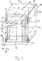
- Fig. 1 shows a dishwasher 2 with a view towards the front side 4.
- a door opening 6 in order to provide the interior of the dishwasher 2 forming rinse tank 8 with items to be washed 10 can.
- a door 12 which closes the door opening 6 during operation is therefore indicated unfolded.
- the dishwasher 2 is set up ready for operation, ie with your side walls in Direction of a vertical 14 aligned.
- a lower basket 18, in an upper region 20 of the washing container 8, an upper basket 22 is arranged.
- Upper basket 22 and lower basket 18 are held on the washing container 8 by means of guide rails 24 or other holding / Auszieh wornen and along the arrow 26 to the door opening 6 out, ie in the longitudinal direction of the dishwasher to the front 4 out pulled out.
- the upper basket 22 includes an approximately perpendicular side wall 28 which defines an approximately horizontally extending bottom wall 30. Both in the lower basket 18 and in the upper basket 22 ware 10 is inserted.
- the upper basket 22 has a fixed first partial area 32 and a second partial area 34 that is movable relative to the first partial area 32.
- the second portion 34 forms a - seen in the illustrated plan view from the front of the door opening 6 - right side portion 36 of the upper basket 22. This is thus the right guide rail 24 faces.
- the second portion 34 could also be arranged in an embodiment, not shown, on the opposite left side region.
- the bottom wall 30 contains support structures 41 for simplified or improved storage of ware 10.
- Fig. 2 shows the upper basket 22 in detail.
- the second portion 34 includes a portion 38 of the bottom wall 30, and a portion of the side wall 28.
- the first portion 32 includes the remaining portion 40 of the bottom wall 30 and the side walls 28.
- the portion 39 thus forms an approximately perpendicular partition 42. This delimits the part 40 and section 38 of the bottom wall to an opening 53 from.
- the bottom wall 30 extends approximately parallel to a horizontal 48.
- the part 40 and the portion 38 of the bottom wall 30 are in Fig. 2 shown in different hatching.
- the section 38 is designed to be movable relative to the remaining part 40 or the rest of the upper basket 22, that is to say the first partial region 32.
- the mobility consists here in a translational displacement of the entire second portion 34 (section 38 and section 39) relative to the first portion 32 in or against the direction of the arrow 46, ie parallel to the course of the bottom wall 30.
- the left end position is shown as position A.
- the opening 53 is thus maximally large.
- the section 38 completely overlaps the part 40.
- Shown dashed is also the second end position as position B.
- the second portion 32 is moved to the right.
- the opening 53 is then completely covered by the portion 38 of the bottom wall 30.
- the upper basket 22 thus corresponds to a top basket with about the same amount of storage space for dishes as in a conventional upper basket.
- the dividing wall 42 actually forms the side wall 28 delimiting the upper basket on the right side. Section 38 and part 40 do not overlap or only minimally overlap.
- the second portion 34 and thus the partition 42 is located at an intermediate position, the position C (dash-dotted lines), the opening 53 is only half as large. Section 38 and Part 40 overlap approximately in half.
- the locking of the second portion 34 and the first portion 32 in or the adjustment between the positions A-C is carried out by hooks, latching, snap, clamp connections or the like, not shown.
- the section 38 can be easily changed between the positions A - C by an operator, not shown.
- the section 38 can continue to be used to store more items to be washed 10 on the section 38 when a relation to the position A reduced opening 53 for high items 10 is sufficient.
- Fig. 2 also indicates an upper basket shower or rotatably mounted spray arm as an exemplary sprayer 44, which is associated with the upper basket 22 to pressurize it with not shown wash liquor.
- the spray device 44 is preferably coupled to the underside of the fixed first portion 32 of the bottom wall 30.
- the sprayer 44 in the direction of the arrow 46, ie in the transverse direction of the dishwasher 2 to the left or right, ie away from the second portion 34 or on these to be displaced.
- it is motion-coupled with the second portion 34.
- An adjustment of the second portion 34 thus also causes an adjustment of the spray 44.
- the shift can be done here - not shown - via a direct connection to the second portion 34. Both components then go the same way in an adjustment. Alternatively, a translation, e.g. done via a not shown linkage. The paths covered are then different.
- Fig. 3 shows the upper basket 22 in an exploded view, ie disassembled into the first portion 32 and the second portion 34.
- the portion 32 forms a base frame or main part of the upper basket 22, which in itself as a stable unit to the guide rails 24 (in Figure 3 not shown) is attached.
- a part of the side wall 28 and the part 40 of the bottom wall 30 is also according to Fig.1 extendable from the upper area 20.
- the second portion 34 is mounted after assembly with the first portion 32 at this slidably in the direction of arrow 46.
- Fig. 4 again shows the three positions AC, in which the second portion 34 is shifted to different degrees to the first portion 32 out and form different sized openings 53 in the upper basket.
- the partition wall 42 forms a stop element 43 for (in Fig. 4 not shown) items 10, which extends through the opening 53 from bottom to top.
- the partition wall 42 is not present forms, for example, the opening 53 facing edge of the portion 38, the stop element 43rd
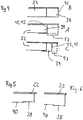
- Figure 5 shows an embodiment of the invention, in which the portion 38 of the bottom wall 30 is above the portion 40 of the bottom wall 30.
- Figure 6 shows the alternative variant with extending below the part 40 section 38.
- the alternatives thus form, for example, a second subregion 34 "inside” or “outside” the rest of the upper basket 22.
- Figure 7 shows an automatic movement coupling between the second portion 34 and a spray 44 such.
- B a rotatably mounted spray arm. If the second portion is moved from position B in the direction of arrow 46 in the position A, also follows the sprayer 44 of this movement.
- the sprayer 44 is therefore always centered to the respective bottom wall 30, which has different extent in the various positions A, B, C by different overlapping of the portion 38 with the part 40.
- the sprayer 44 is thus connected to the second portion 34.
- the connection can be made directly (same adjustment paths) or with a translation. It is thus achieved that the spray device 44 extends only to a maximum extent to the edge of the opening 53, but never protrudes into this or its area.
Landscapes
- Washing And Drying Of Tableware (AREA)
Abstract
- mit einem im oberen Bereich (20) eines Spülbehälters (8) angeordneten Oberkorb (22) zur Aufnahme von Spülgut (10),
- wobei der Oberkorb (22) eine, insbesondere eine etwa waagerecht verlaufende, Bodenwand (30) und eine diese umgrenzende, nach oben abstehende, insbesondere etwa senkrecht verlaufende, Seitenwand (28) enthält,
- weist der Oberkorb (22) einen feststehenden ersten Teilbereich (32) und einen zwischen mindestens zwei Positionen (A-C) relativ zum ersten Teilbereich (32) und parallel zum Verlauf der Bodenwand (30) translatorisch verschiebbaren zweiten Teilbereich (34) auf,
- wobei der zweite Teilbereich (34) einen Abschnitt (38) der Bodenwand (30) enthält,
- und der zweite Teilbereich (34) in mindestens einer Position (A-C) eine Öffnung (53) in der Bodenwand (30) freigibt.
Description
- Die Erfindung betrifft eine Geschirrspülmaschine mit einem verstellbaren Oberkorb.
- Eine Geschirrspülmaschine, insbesondere Haushaltsgeschirrspülmaschine, weist einen Spülbehälter auf, welcher in der Regel quaderförmig ist und an der Vorderseite eine Türöffnung besitzt, die durch eine Fronttür verschließbar ist. Ortsangaben wie "oben", "unten" oder "vorne" beziehen sich auf die Betriebsposition der Maschine, wenn diese betriebsbereit aufgestellt ist. Im oberen Bereich des Spülbehälters ist ein Oberkorb angeordnet, im unteren Bereich i.d.R. ein Unterkorb. In Unter- und Oberkorb wird Spülgut, z. B. Töpfe, Geschirrteile und Besteck eingelagert. Der maximal zur Verfügung stehende Höhenraum für Geschirrteile im Unterkorb ist bezüglich der verfügbaren Höhe durch den Oberkorb bzw. dessen unten liegende Bodenwand begrenzt. Eine übliche maximale Tellergröße, die in einer Geschirrspülmaschine senkrecht eingestellt werden kann, beträgt heute rund 33 - 35 cm. Problematisch ist das Spülen von höheren Gegenständen bzw. größerem Spülgut, wie z.B. Backblechen, hohen Töpfen oder Tellern mit Übergrößen, wie Pizzatellern oder Servierplatten. Es ist bekannt, diese Teile quer über den Unterkorb zu legen. Dadurch wird Platz für weitere zu spülende Teile verschwendet. Alternativ ist es bekannt, eine z.B. aus der
DE 297 12 895 U1 bekannte Backblechbrause einzusetzen. Alternativ ist es bekannt, den Oberkorb als Ganzes aus dem Spülbehälter zu entnehmen, wobei dieser dann nicht mehr für die Beladung mit zusätzlichem Spülgut zur Verfügung steht. - Aus der
DE 200 19 480 U1 ist eine Geschirrspülmaschine bekannt, welche im oberen Bereich des Spülbehälters anstelle eines Oberkorbes z.B. zwei gegen die Wand des Spülbehälters klappbare Gestellborde enthält. Hier kann beispielsweise ein Gestellbord nach unten geklappt werden, um eine Art Oberkorb zu erhalten, auf welchem Spülgut platziert werden kann. Das andere Gestellbord kann nach oben geklappt werden. Der freiwerdende Raum im oberen Bereich des Spülbehälters steht dann für besonders großes Spülgut zur Verfügung, das im korrespondierenden Bereich des Unterkorbes platziert werden kann. - Alternativ ist aus der
US 2010/0314977 A1 ein Oberkorb für eine Geschirrspülmaschine bekannt. Ein Teil der Bodenwand ist zusammen mit einem Teil der Seitenwand verschwenkbar, um in einem Teilbereich des Oberkorbs eine Lücke zu schaffen. In die freiwerdende Lücke kann dann von unten her wieder großes Spülgut ragen, die sich im Unterkorb befinden. Der restliche Oberkorb steht weiterhin für die Verwendung von Spülgut zur Verfügung. - Ziel der vorliegenden Erfindung ist es, in einer Geschirrspülmaschine ein gleichzeitiges Spülen von übergroßen Geschirrteilen und/oder Haushalts- bzw. Kochutensilien mit der üblichen täglichen anfallenden Geschirrmenge zu erlauben, ohne eine stark eingeschränkte Gesamtfunktionalität von Ober- und Unterkorb in Kauf nehmen zu müssen.
- Aufgabe der vorliegenden Erfindung ist es, eine verbesserte Geschirrspülmaschine anzugeben.
- Die Aufgabe wird gelöst durch eine Geschirrspülmaschine gemäß Patentanspruch 1. Diese weist einen Spülbehälter mit einem im oberen Bereich des Spülbehälters angeordneten Oberkorb zur Aufnahme von Spülgut auf. Der Oberkorb weist eine, insbesondere etwa waagerecht verlaufende Bodenwand und eine diese umgrenzende, nach oben ragende bzw. abstehende, insbesondere etwa senkrecht verlaufende, Seitenwand bzw. Geschirrkorbboden-Begrenzungswand auf. Die Bodenwand ist insbesondere derjenige Bereich des Geschirrkorbs, der von dessen Seitenwand ringsrum umgrenzt bzw. eingeschlossen ist. Bei einem rechteckförmigen Grundriss des Geschirrkorbs kann dessen Bodenwand vorzugsweise auf vier Seiten von der Seitenwand umfasst sein. Die Seitenwand kann also mehrere Wandungsteile aufweisen. Die Boden- und Seitenwand des Oberkorbes sind hierbei z.B. Metall- oder Kunststoff-Gitterstrukturen bzw. Korbmatten oder gelochte Kunststoffelemente. "In etwa waagerecht" bedeutet hierbei, dass Spülgut auf der Bodenwand ablegbar ist, eine gewisse Neigung, also Kippung aus der Waagerechten kann hierbei vorgesehen sein. Teil der Bodenwand können also durchaus beispielsweise und 10° -20° um eine Längs- oder Querachse der Geschirrspülmaschine gekippt sein.
- Der Oberkorb weist einen feststehenden ersten Teilbereich und einen zweiten, beweglich ausgebildeten Teilbereich auf. Der erste Teilbereich umfasst nur einen Teil der Bodenwand und die gesamte oder einen Teil der Seitenwand. Der zweite Teilbereich ist zwischen mindestens zwei Positionen relativ zum ersten Teilbereich bewegbar. Die Bewegung erfolgt durch eine translatorische Verschiebung parallel zum Verlauf der Bodenwand, also insbesondere waagerecht relativ zum ersten Teilbereich. Der zweite Teilbereich enthält einen Abschnitt der Bodenwand des Oberkorbes. In mindestens einer Position gibt der zweite Teilbereich eine Öffnung in der Bodenwand frei.
- Der zweite Teilbereich des Oberkorbes bildet kein separates, vom restlichen Oberkorb getrenntes Einbauteil, sondern einen integralen Bestandteil des Oberkorbes, gehört also zu diesem. Mit anderen Worten ist der Oberkorb also zwischen verschiedenen Gestaltungsvarianten bezüglich seiner Geometrie bzw. der Ausdehnung seiner Bodenwand transformierbar.
- Der gesamte Bodenbereich des Oberkorbes ist erfindungsgemäß damit so ausgestaltet, dass zumindest ein Teil dessen, nämlich der dem zweiten Teilbereich zugehörige Abschnitt der Bodenwand, verschiebbar ist. In mindestens einer Position wird eine Öffnung in der Bodenwand freigegeben. So wird Platz für darunter einzusetzende größere Geschirrteile geschaffen, die dann die Bodenwand im Bereich der Öffnung durchsetzen können. Erfindungsgemäß wird damit Platz für höheres Spülgut im Unterkorb zur Verfügung gestellt, ohne den Oberkorb oder Teile dessen entnehmen zu müssen.
- Für unterschiedliche Positionen hat der zweite Teilbereich bzw. dessen Abschnitt der Bodenwand dank der rein translatorischen Verschiebung stets die gleiche Höhenlage in Bezug auf den restlichen Teil der Bodenwand des ersten Teilbereichs. Die Bodenwand bleibt als solche im wesentlichen unverändert in einer Ebene erhalten, wird also nur hinsichtlich ihrer Fläche verkleinert oder vergrößert.
- Die Arretierung des zweiten Teilbereiches in einer Position erfolgt z.B. durch Clips, Haken, Rast-, Klemmvorrichtungen oder ähnliche Elemente, die dem ersten oder zweiten Teilbereich zugeordnet sein können. Die Erfindung ist insbesondere mit einem segmentierten Sprühsystem kombinierbar, welches beispielsweise aus der
EP 1 458 276 B1 bekannt ist. - Sonstige vorteilhafte Aus- und Weiterbildungen der Erfindung sind in den Unteransprüchen wiedergegeben.
- In einer bevorzugten Ausführungsform ist der zweite Teilbereich zwischen zwei Positionen stufenlos relativ zum ersten Teilbereich verschiebbar. Somit kann auch die Öffnung stufenlos verkleinert oder vergrößert werden.
- In einer weiteren zweckmäßigen Ausführungsform der Erfindung bedeckt der Abschnitt in zumindest einer Position zusammen mit der Bodenwand des ersten Teilbereiches stets die gesamte, von der Seitenwand umgrenzte Fläche. Mit anderen Worten entstehen so in der Bodenwand des Oberkorbes keine nicht nutzbaren Lücken, sondern der Oberkorb ist in seiner gesamten Grundfläche durch Auflegen von Spülgut nutzbar. In dieser Position gleicht dann die gesamte Bodenwand derjenigen eines herkömmlichen, nicht transformierbaren Oberkorbes. Die Bodenwand ist dann z.B. im wesentlichen eben und erstreckt sich über die gesamte zur Verfügung stehende Fläche zwischen den Seitenwänden. Der Oberkorb ist dann zwischen mindestens zwei Positionen, nämlich der eben beschriebenen "Normal"-Position - entsprechend einem herkömmlichen Oberkorb - und einer weiteren Position mit einer Öffnung für erhöhtes Spülgut im Unterkorb verstellbar.
- In anderen Positionen enthält der Oberkorb also im zweiten Teilbereich dann die Öffnung in der Bodenwand, die einen Durchtritt von im Unterkorb befindlichen Spülgut durch den Oberkorb bzw. dessen Bodenwand erlaubt. In diesem Bereich kann dann die maximale Höhe des Spülbehälters für im Unterkorb befindliches Spülgut genutzt werden, ohne vom Oberkorb behindert zu werden.
- In einer weiteren zweckmäßigen Ausführungsform der Erfindung umfasst der zweite Teilbereich einen Teilbereich der Seitenwand. Die Seitenwand ist also mit dem Abschnitt zusammen bewegbar. Grenzt die Seitenwand den zweiten Abschnitt zur Öffnung hin ab, so bildet diese außerdem eine Barriere für in den Oberkorb eingelegtes Spülgut, das somit nicht in die Öffnung fallen kann. Mit anderen Worten wird damit in den verschiedenen Positionen der gesamte Oberkorb - Wand und Boden - verkleinert oder vergrößert.
- In einer anderen vorteilhaften Ausführungsform der Erfindung ist der zweite Teilbereich in einem Seitenbereich des Oberkorbes angeordnet. Der Oberkorb ist in der Regel zur Front der Spülmaschine, also durch die Türöffnung hindurch aus dem Spülbehälter heraus ausziehbar. Der angesprochene Seitenbereich ist dann der linke oder rechte Randbereich des Oberkorbes, der also jeweils an eine linke oder rechte Auszugschiene angrenzt. So kann auch bei Einlegen von hohem Spülgut im Unterkorb sowohl dieser als auch der Oberkorb ohne störenden Eingriff des Spülgutes eingeschoben oder ausgezogen werden. Der Teilbereich kann alternativ aber auch z.B. an der Vorder- oder Rückseite des Oberkorbes oder in einem Mittelbereich angeordnet sein.
- In einer bevorzugten Ausführungsform ist in der Spülmaschine dem Oberkorb eine Sprüheinrichtung, insbesondere ein rotierbarer Sprüharm oder eine Oberkorbbrause, zugeordnet. Diese beaufschlagt den Oberkorb mit Spülflotte. Die Sprüheinrichtung ist mit dem zweiten Teilbereich vorteilhafterweise bewegungsgekoppelt. Wird der Oberkorb verändert, indem der zweite Teilbereich verschoben wird, ändert damit auch die Sprüheinrichtung ihren Ort oder ihre Ausrichtung. So passt sich die Beaufschlagung des Oberkorbes mit Spülflotte durch die Sprüheinrichtung stets optimal an die aktuelle Gestalt des Oberkorbes an. Weist beispielsweise in einer Position der Oberkorb keine Öffnung auf, füllt also den gesamten Raum in der Spülmaschine aus, wird die Sprüheinrichtung zum zweiten Teilbereich hin verschoben und überstreicht damit im Wesentlichen den gesamten Oberkorbbereich zentral. Ist der Oberkorb derart transformiert, dass eine Öffnung im Oberkorb vorhanden ist, wird die Sprüheinrichtung vom zweiten Teilbereich weg verschoben und bespült so zentral den restlichen Bereich des Bodens des Oberkorbes im ersten Teilbereich.
- In einer vorteilhaften Variante dieser Ausführungsform erstreckt sich die Sprüheinrichtung in jeder Position vom ersten Teilbereich her höchstens bis zur Öffnung. Die Sprüheinrichtung ragt also niemals über den Rand der Öffnung in diese hinein. Die Öffnung wird nicht von der Sprüheinrichtung wie z.B. einem sich drehenden Sprüharm überstrichen. Vom Unterkorb durch die Öffnung ragendes Spülgut kann also die Sprüheinrichtung, insbesondere einen rotierbar gelagerten Sprüharm nicht blockieren. Besonders hier kann durch die o.g. Bewegungskopplung erreicht werden, dass der Sprüharm bei Schaffung einer Öffnung im Oberkorb - durch die Bewegung des zweiten Teilbereiches - automatisch aus dem Bereich der Öffnung herausbewegt wird.
- In einer weiteren vorteilhaften Variante dieser Ausführungsform befindet sich die Sprüheinrichtung in jeder Position durch die Bewegungskopplung automatisch mittig bezüglich der aus dem Abschnitt der Bodenwand des zweiten Teilbereiches und dem restlichen Teil der Bodenwand gebildeten gesamten Bodenwand. Mit anderen Worten befindet sich die Sprüheinrichtung insbesondere stets in der Mitte der unter Wegnahme der Öffnung verbleibenden Rest-Bodenfläche des Oberkorbes.
- Die vorstehend erläuterten und/oder in den Unteransprüchen wiedergegebenen vorteilhaften Aus- und Weiterbildungen der Erfindung können dabei - außer z.B. in den Fällen eindeutiger Abhängigkeiten oder unvereinbarer Alternativen - einzeln oder aber auch in beliebiger Kombination miteinander bei der erfindungsgemäßen Geschirrspülmaschine zur Anwendung kommen.
- Die Erfindung und ihre vorteilhaften Aus- und Weiterbildungen sowie deren Vorteile werden nachfolgend anhand von Zeichnungen näher erläutert.
- Es zeigen, jeweils in einer schematischen Prinzipskizze:
-
Fig. 1 eine Geschirrspülmaschine mit erfindungsgemäß ausgebildetem Oberkorb in perspektivischer Darstellung, -
Fig. 2 den Oberkorb ausFig. 1 im Detail, -
Fig. 3 den Oberkorb ausFig. 1 in Explosionsdarstellung, -
Fig. 4 den Oberkorb ausFig.1 in Seitenansicht -
Fig. 5,6 zwei vorteilhafte Ausführungsformen für Oberkörbe und -
Fig.7 einen Oberkorb mit bewegungsgekoppelter Sprüheinrichtung. -
Fig. 1 zeigt eine Geschirrspülmaschine 2 mit Blickrichtung auf deren Vorderseite 4. Dort befindet sich eine Türöffnung 6, um den den Innenraum der Geschirrspülmaschine 2 bildenden Spülbehälter 8 mit Spülgut 10 versorgen zu können. Eine im Betrieb die Türöffnung 6 verschließende Tür 12 ist daher aufgeklappt angedeutet. Die Geschirrspülmaschine 2 ist betriebsbereit aufgestellt, d.h. mit Ihren Seitenwänden in Richtung einer Senkrechten 14 ausgerichtet. In einem unteren Bereich 16 des Spülbehälters 8 ist ein Unterkorb 18, in einem oberen Bereich 20 des Spülbehälters 8 ein Oberkorb 22 angeordnet. Oberkorb 22 und Unterkorb 18 sind am Spülbehälter 8 mit Hilfe von Führungsschienen 24 oder sonstigen Halte-/Auszieheinrichtungen gehalten und entlang des Pfeils 26 zur Türöffnung 6 hin, also in Längsrichtung der Spülmaschine zu deren Vorderseite 4 hin ausziehbar. Der Oberkorb 22 umfasst eine etwa senkrecht verlaufende Seitenwand 28, welche eine etwa waagerecht verlaufende Bodenwand 30 umgrenzt. Sowohl im Unterkorb 18 als auch im Oberkorb 22 ist Spülgut 10 eingelegt. - Der Oberkorb 22 weist einen feststehenden ersten Teilbereich 32 sowie einen relativ zum ersten Teilbereich 32 beweglichen zweiten Teilbereich 34 auf. Im Ausführungsbeispiel bildet der zweite Teilbereich 34 einen - bei der dargestellten Draufsicht von vorne auf die Türöffnung 6 gesehen - rechten Seitenbereich 36 des Oberkorbes 22. Dieser ist also der rechten Führungsschiene 24 zugewandt. Der zweite Teilbereich 34 könnte jedoch in einer nicht dargestellten Ausführungsform auch auf dem gegenüberliegenden linken Seitenbereich angeordnet sein. Die Bodenwand 30 enthält Stützstrukturen 41 zur vereinfachten bzw. verbesserten Ablage von Spülgut 10.
-
Fig. 2 zeigt den Oberkorb 22 im Detail. In der gezeigten Ausführungsform umfasst der zweite Teilbereich 34 einen Abschnitt 38 der Bodenwand 30, und einen Teil der Seitenwand 28. Der erste Teilbereich 32 umfasst den restlichen Teil 40 der Bodenwand 30 sowie der Seitenwände 28. Der Abschnitt 39 bildet damit eine etwa senkrecht verlaufende Trennwand 42. Diese grenzt den Teil 40 und Abschnitt 38 der Bodenwand zu einer Öffnung 53 hin ab. Die Bodenwand 30 verläuft in etwa eben parallel zu einer Waagerechten 48. - Der Teil 40 und der Abschnitt 38 der Bodenwand 30 sind in
Fig. 2 unterschiedlich schraffiert dargestellt. Insbesondere der Abschnitt 38 ist gegenüber dem restlichen Teil 40 bzw. dem Rest des Oberkorbes 22, also dem ersten Teilbereich 32 beweglich ausgeführt. Die Beweglichkeit besteht hier in einer translatorischen Verschiebbarkeit des gesamten zweiten Teilbereiches 34 (Abschnitt 38 und Abschnitt 39) gegenüber dem ersten Teilbereich 32 in oder entgegen der Richtung des Pfeiles 46, also parallel zum Verlauf der Bodenwand 30. InFig.2 ist die nach links geschobene Endposition als Position A gezeigt. - Die Öffnung 53 ist damit maximal groß. Der Abschnitt 38 überlappt den Teil 40 vollständig.
- Gestrichelt eingezeichnet ist auch die zweite Endstellung als Position B. Hier ist der zweite Teilbereich 32 ganz nach rechts verschoben. Die Öffnung 53 ist dann vollständig vom Abschnitt 38 der Bodenwand 30 bedeckt. Der Oberkorb 22 entspricht damit einem Oberkorb mit etwa gleich großer Abstellfläche für Geschirr wie bei einem herkömmlichen Oberkorb. Die Trennwand 42 bildet tatsächlich die den Oberkorb an der rechten Seite begrenzende Seitenwand 28. Abschnitt 38 und Teil 40 überlappen sich nicht oder nur minimal.
- Befindet sich der zweite Teilbereich 34 und damit die Trennwand 42 an einer Zwischenposition, der Position C (strichpunktiert gezeichnet), so ist die Öffnung 53 nur halb so groß. Abschnitt 38 und Teil 40 überlappen sich etwa zur Hälfte.
- Die Arretierung des zweiten Teilbereiches 34 bzw. am ersten Teilbereich 32 in bzw. die Verstellung zwischen den Positionen A-C erfolgt durch nicht dargestellte Haken, Rast-, Schnapp-, Klemmverbindungen oder ähnliches. So kann der Abschnitt 38 von einem nicht dargestellten Bediener leicht zwischen den Positionen A - C gewechselt werden.
- Wie in
Fig. 1 zu erkennen ist, bietet die Positionierung des Abschnitts 38 in der Position A und C im oberen Bereich 20, also im Bereich des Oberkorbes 22 Platz für besonders hohes Spülgut 10, welches im Unterkorb 18 gelagert ist. In der Position C kann allerdings der Abschnitt 38 weiterhin dazu benutzt werden, um weiteres Spülgut 10 auf dem Abschnitt 38 abzulegen, wenn eine gegenüber der Position A verkleinerte Öffnung 53 für hohes Spülgut 10 ausreicht. - In der Position B steht im Unterkorb 18 zwar kein Höhenraum mehr für überhöhtes Spülgut zur Verfügung, dafür steht der gesamte Oberkorb 22 zur Beladung zur Verfügung. Es ergibt sich eine nahezu ebene gesamte Bodenwand 30.
-
Fig. 2 zeigt außerdem angedeutet eine Oberkorbbrause oder rotierbar gelagerten Sprüharm als beispielhafte Sprüheinrichtung 44, die dem Oberkorb 22 zugeordnet ist, um diesen mit nicht dargestellter Spülflotte zu beaufschlagen. Die Sprüheinrichtung 44 ist vorzugsweise an der Unterseite des feststehenden ersten Teilbereichs 32 der Bodenwand 30 angekoppelt. Um das Spülergebnis optimal an die jeweils gewählte Position A - C des zweiten Teilbereiches 34 anpassen zu können, ist die Sprüheinrichtung 44 in Richtung des Pfeils 46, also in Querrichtung der Geschirrspülmaschine 2 nach links oder rechts, also vom zweiten Teilbereich 34 weg oder auf diesen zu verschiebbar. Hierbei ist sie mit dem zweiten Teilbereich 34 bewegungsgekoppelt. Eine Verstellung des zweiten Teilbereiches 34 bewirkt also auch eine Verstellung der Sprüheinrichtung 44. Dadurch kann sichergestellt werden, dass die Sprüheinrichtung bezüglich der sich jeweils - je nach zurückgelegtem translatorischen Verschiebeweg des beweglichen Teils 40 - insgesamt ergebenden Gesamtfläche des Bodens, die sich aus der Bodenfläche des feststehenden Teilbereichs 32 und dem von oben frei zugänglichen, die Öffnung 53 teilweise oder ganz abdeckenden Bodenfläche des beweglichen Teilbereichs 34 zusammensetzt, ausgerichtet werden kann, insbesondere z. B. auf das Zentrum dieser zusammengesetzten Bodenfläche. - Die Verschiebung kann hierbei - nicht dargestellt - über eine direkte Anbindung am zweiten Teilbereich 34 erfolgen. Beide Komponenten legen dann bei einer Verstellung gleiche Wege zurück. Alternativ kann eine Übersetzung, z.B. über ein nicht dargestelltes Gestänge erfolgen. Die zurückgelegten Wege sind dann unterschiedlich.
-
Fig. 3 zeigt den Oberkorb 22 in Explosionsdarstellung, d.h. zerlegt in den ersten Teilbereich 32 und den zweiten Teilbereich 34. Der Teilbereich 32 bildet einen Grundrahmen bzw. Hauptteil des Oberkorbes 22, der an sich als stabile Einheit an den Führungsschienen 24 (inFig.3 nicht gezeigt) befestigt ist. Zu erkennen ist ein Teil der Seitenwand 28 und der Teil 40 der Bodenwand 30. Dieser ist damit auch gemäßFig.1 aus dem oberen Bereich 20 ausziehbar. Der zweite Teilbereich 34 ist nach dem Zusammenfügen mit dem ersten Teilbereich 32 an diesem verschiebbar in Richtung des Pfeils 46 gelagert. Zu erkennen ist die Zugehörigkeit des Abschnittes 39 der Seitenwand 28 und des Abschnitts 38 der Bodenwand 30 zum zweiten Teilbereich 34. -
Fig. 4 zeigt nochmals die drei Positionen A-C, bei denen der zweite Teilbereich 34 unterschiedlich weit zum ersten Teilbereich 32 hin verschoben ist und sich im Oberkorb unterschiedlich große Öffnungen 53 bilden. In den Positionen A und C bildet die Trennwand 42 ein Anschlagelement 43 für (inFig. 4 nicht dargestelltes) Spülgut 10, welches durch die Öffnung 53 von unten nach oben reicht. Ist in einer nicht gezeigten Ausführungsform die Trennwand 42 nicht vorhanden, bildet z.B. der der Öffnung 53 zugewandte Rand des Abschnitts 38 das Anschlagelement 43. -
Fig.5 zeigt eine Ausführungsform der Erfindung, bei der der Abschnitt 38 der Bodenwand 30 oberhalb des Teils 40 der Bodenwand 30 liegt.Fig.6 zeigt die alternative Variante mit unterhalb des Teils 40 verlaufendem Abschnitt 38. Gleiches gilt für die Seitenwand 28 bzw. deren Abschnitt 39, Kombinationen sind möglich. Die Alternativen bilden also z.B. einen "innerhalb" oder "außerhalb" des restlichen Oberkorbes 22 liegenden zweiten Teilbereich 34. -
Fig.7 zeigt eine automatische Bewegungskopplung zwischen dem zweiten Teilbereich 34 und einer Sprüheinrichtung 44 wie z. B. einem rotierbar gelagerten Sprüharm. Wird der zweite Teilbereich aus der Position B in Richtung des Pfeils 46 in die Position A verschoben, folgt auch die Sprüheinrichtung 44 dieser Bewegung. Die Sprüheinrichtung 44 befindet sich daher stets mittig zur jeweiligen Bodenwand 30, die in den verschiedenen Positionen A,B,C durch verschiedene Überlappung des Abschnitts 38 mit dem Teil 40 verschiedene Ausdehnung besitzt. Die Sprüheinrichtung 44 ist also an den zweiten Teilbereich 34 angebunden. Die Anbindung kann direkt (gleiche Verstellwege) oder mit einer Übersetzung erfolgen. So wird erreicht, dass die Sprüheinrichtung 44 sich nur jeweils bis maximal zum Rand der Öffnung 53 erstreckt, jedoch nie in diese bzw. deren Bereich hineinragt. -
- 2
- Geschirrspülmaschine
- 4
- Vorderseite
- 6
- Türöffnung
- 8
- Spülbehälter
- 10
- Spülgut
- 12
- Tür
- 14
- Senkrechte
- 16
- unterer Bereich
- 18
- Unterkorb
- 20
- oberer Bereich
- 22
- Oberkorb
- 24
- Führungsschiene
- 26
- Pfeil
- 28
- Seitenwand
- 30
- Bodenwand
- 32
- erster Teilbereich
- 34
- zweiter Teilbereich
- 36
- Seitenbereich
- 38
- Abschnitt
- 39
- Abschnitt
- 40
- Teil
- 41
- Stützstruktur
- 42
- Trennwand
- 43
- Anschlagelement
- 44
- Sprüheinrichtung
- 46
- Pfeil
- 48
- Waagerechte
- 53
- Öffnung
- A-C
- Position
Claims (9)
- Geschirrspülmaschine (2),- mit einem im oberen Bereich (20) eines Spülbehälters (8) angeordneten Oberkorb (22) zur Aufnahme von Spülgut (10),- wobei der Oberkorb (22) eine, insbesondere eine etwa waagerecht verlaufende, Bodenwand (30) und eine diese umgrenzende, nach oben abstehende, insbesondere etwa senkrecht verlaufende, Seitenwand (28) enthält,- wobei der Oberkorb (22) einen feststehenden ersten Teilbereich (32) und einen zwischen mindestens zwei Positionen (A-C) relativ zum ersten Teilbereich (32) und parallel zum Verlauf der Bodenwand (30) translatorisch verschiebbaren zweiten Teilbereich (34) aufweist,- wobei der zweite Teilbereich (34) einen Abschnitt (38) der Bodenwand (30) enthält,- und der zweite Teilbereich (34) in mindestens einer Position (A-C) eine Öffnung (53) in der Bodenwand (30) freigibt.
- Geschirrspülmaschine (2) nach Anspruch 1, mit einem zwischen zwei Positionen (A-C) stufenlos relativ zum ersten Teilbereich (32) verschiebbaren zweiten Teilbereich (34).
- Geschirrspülmaschine (2) nach einem der vorhergehenden Ansprüche, bei der der Abschnitt (38) in zumindest einer Position (A-C) zusammen mit dem vom ersten Teilbereich (32) gebildeten Teil (40) der Bodenwand (30) die gesamte, von der Seitenwand (28) umgrenzte Fläche bedeckt.
- Geschirrspülmaschine (2) nach einem der vorhergehenden Ansprüche, bei der der zweite Teilbereich (34) einen Abschnitt (39) der Seitenwand (28) enthält.
- Geschirrspülmaschine (2) nach einem der vorhergehenden Ansprüche, bei der der zweite Teilbereich (34) in einem Seitenbereich (36) des Oberkorbes (22) angeordnet ist.
- Geschirrspülmaschine (2) nach einem der vorhergehenden Ansprüche, bei der der zweite Teilbereich (34) ein Anschlagelement (43) für die Öffnung (53) durchsetzendes Spülgut (10) aufweist.
- Geschirrspülmaschine (2) nach einem der vorhergehenden Ansprüche, mit einer dem Oberkorb (22) zugeordneten Sprüheinrichtung (44), insbesondere ein rotierbar gelagerter Sprüharm oder eine Oberkorbbrause, die mit dem zweiten Teilbereich (34) bewegungsgekoppelt ist.
- Geschirrspülmaschine (2) nach Anspruch 7, bei der die Sprüheinrichtung, insbesondere Oberkorbbrause (44) in jeder Position (A-C) sich vom ersten Teilbereich (32) her höchstens bis zur Öffnung (53) erstreckt.
- Geschirrspülmaschine (2) nach Anspruch 7 oder 8, bei der sich die Sprüheinrichtung (44) in jeder Position (A-C) mittig bezüglich der aus dem vom ersten Teilbereich (32) gebildeten Teil (40) der Bodenwand (30) und dem Abschnitt (38) gebildeten Bodenwand (30) befindet.
Applications Claiming Priority (1)
| Application Number | Priority Date | Filing Date | Title |
|---|---|---|---|
| DE102011004954A DE102011004954A1 (de) | 2011-03-02 | 2011-03-02 | Geschirrspülmaschine mit verstellbarem Oberkorb |
Publications (3)
| Publication Number | Publication Date |
|---|---|
| EP2494907A2 true EP2494907A2 (de) | 2012-09-05 |
| EP2494907A3 EP2494907A3 (de) | 2013-06-05 |
| EP2494907B1 EP2494907B1 (de) | 2019-06-05 |
Family
ID=45655778
Family Applications (1)
| Application Number | Title | Priority Date | Filing Date |
|---|---|---|---|
| EP12155481.0A Active EP2494907B1 (de) | 2011-03-02 | 2012-02-15 | Geschirrspülmaschine mit verstellbarem Oberkorb |
Country Status (3)
| Country | Link |
|---|---|
| US (1) | US9265403B2 (de) |
| EP (1) | EP2494907B1 (de) |
| DE (1) | DE102011004954A1 (de) |
Citations (4)
| Publication number | Priority date | Publication date | Assignee | Title |
|---|---|---|---|---|
| DE29712895U1 (de) | 1997-07-25 | 1997-10-02 | Bosch-Siemens Hausgeräte GmbH, 81669 München | Sprüheinrichtung für eine Haushalt-Geschirrspülmaschine mit wenigstens einer weiteren Sprüheinrichtung |
| DE20019480U1 (de) | 1999-11-29 | 2001-02-15 | Electrolux Zanussi S.P.A., Pordenone | Geschirrspülmaschine mit einem an die zu spülenden Geschirrteile anpassbaren Fassungsvermögen |
| EP1458276B1 (de) | 2001-12-19 | 2010-04-28 | BSH Bosch und Siemens Hausgeräte GmbH | Vorrichtung zum ansteuern des spülvorgangs von spülgut in einer geschirrspülmaschine |
| US20100314977A1 (en) | 2009-06-11 | 2010-12-16 | Mallory Brian L | Adjustable upper dishwasher rack |
Family Cites Families (3)
| Publication number | Priority date | Publication date | Assignee | Title |
|---|---|---|---|---|
| DE29901901U1 (de) * | 1999-02-04 | 2000-06-29 | AEG Hausgeräte GmbH, 90429 Nürnberg | Universal-Ablagetablett mit einer Nutzfläche und Ensemble, bestehend aus mindestens zwei der Geräte Geschirrspüler, Kältegerät und Gargerät mit einem Universal-Ablagetablett |
| DE102008062761B3 (de) * | 2008-12-18 | 2010-03-25 | Miele & Cie. Kg | Besteckschublade für eine Geschirrspülmaschine |
| PL2292140T3 (pl) * | 2009-09-03 | 2014-09-30 | Electrolux Home Products Corp Nv | Pojemnik na srebrne sztućce, zwłaszcza taca na srebrne sztućce i/lub koszyk na srebrne sztućce, jak również zmywarka z takim pojemnikiem na srebrne sztućce |
-
2011
- 2011-03-02 DE DE102011004954A patent/DE102011004954A1/de not_active Withdrawn
-
2012
- 2012-02-15 EP EP12155481.0A patent/EP2494907B1/de active Active
- 2012-02-21 US US13/400,605 patent/US9265403B2/en not_active Expired - Fee Related
Patent Citations (4)
| Publication number | Priority date | Publication date | Assignee | Title |
|---|---|---|---|---|
| DE29712895U1 (de) | 1997-07-25 | 1997-10-02 | Bosch-Siemens Hausgeräte GmbH, 81669 München | Sprüheinrichtung für eine Haushalt-Geschirrspülmaschine mit wenigstens einer weiteren Sprüheinrichtung |
| DE20019480U1 (de) | 1999-11-29 | 2001-02-15 | Electrolux Zanussi S.P.A., Pordenone | Geschirrspülmaschine mit einem an die zu spülenden Geschirrteile anpassbaren Fassungsvermögen |
| EP1458276B1 (de) | 2001-12-19 | 2010-04-28 | BSH Bosch und Siemens Hausgeräte GmbH | Vorrichtung zum ansteuern des spülvorgangs von spülgut in einer geschirrspülmaschine |
| US20100314977A1 (en) | 2009-06-11 | 2010-12-16 | Mallory Brian L | Adjustable upper dishwasher rack |
Also Published As
| Publication number | Publication date |
|---|---|
| EP2494907B1 (de) | 2019-06-05 |
| US9265403B2 (en) | 2016-02-23 |
| US20120222710A1 (en) | 2012-09-06 |
| DE102011004954A1 (de) | 2012-09-06 |
| EP2494907A3 (de) | 2013-06-05 |
Similar Documents
| Publication | Publication Date | Title |
|---|---|---|
| EP2494908B1 (de) | Geschirrspülmaschine mit verstellbarem Oberkorb | |
| DE102013112714B4 (de) | Geschirrspüler | |
| EP2096976B1 (de) | Besteckkorb für eine geschirrspülmaschine und geschirrspülmaschine | |
| DE102011081774B4 (de) | Geschirrspülmaschine mit einer zur Halterung von kleinen Spülgutstücken, insbesondere Besteckteilen, vorgesehenen Aufnahmestruktur | |
| WO2003055375A1 (de) | Besteckkorb für eine geschirrspülmaschine | |
| EP2215957B1 (de) | Geschirrspülmaschine, insbesondere Haushaltsgeschirrspülmaschine | |
| DE102015111994B4 (de) | Spülmaschine in Gestalt einer als Programmautomat ausgebildeten gewerblichen Utensilien- oder Geschirrspülmaschine | |
| DE2610379B2 (de) | Geschirrspülmaschine | |
| WO2013020811A1 (de) | Geschirrspülmaschine mit mindestens einer mit anordnungshinweisen versehenen spülgut-aufnahmestruktur | |
| EP1816944A1 (de) | Spülgutträger für eine geschirrspülmaschine | |
| EP2896345B1 (de) | Spülgut Aufnahmevorrichtung für einen Geschirrkorb eines wasserführenden Haushaltsgeräts, Geschirrkorb für ein wasserführendes Haushaltsgerät und wasserführendes Haushaltsgerät. | |
| EP3236832A1 (de) | Unterkorb für eine haushaltsgeschirrspülmaschine mit unterkorb-anhebung | |
| WO2021122025A1 (de) | Spülgutaufnahme | |
| DE102012016762B4 (de) | Geschirrspülmaschine | |
| EP2494907B1 (de) | Geschirrspülmaschine mit verstellbarem Oberkorb | |
| DE29921601U1 (de) | Geschirrkorb für Geschirrspülmaschinen | |
| DE102012202786A1 (de) | Geschirrspülmaschine mit einem einen nach unten abschwenkbaren Bodenbereich aufweisenden Oberkorb | |
| DE102011004088A1 (de) | Geschirrspülmaschine mit einer beweglichen Tür und zumindest einer Türdichtung | |
| WO2003055376A1 (de) | Vorrichtung zum ablegen von spülgut in einer geschirrspülmaschine | |
| DE102005058665B4 (de) | Geschirrkorb mit lösbaren Spülgutablagen | |
| DE29608871U1 (de) | Geschirrspülmaschine mit Geschirrkörben zum Anordnen von zu spülendem Gut | |
| DE102007048198A1 (de) | Korb für eine Geschirrspülmaschine | |
| WO2010069723A1 (de) | Geschirrspülmaschine sowie einsatzelement für einen besteckkorb einer solchen geschirrspülmaschine | |
| DE10063355A1 (de) | Tür für Haushaltgeräte | |
| DE102015017503B4 (de) | Spülmaschine in Gestalt einer als Programmautomat ausgebildeten gewerblichen Utensilien-oder Geschirrspülmaschine |
Legal Events
| Date | Code | Title | Description |
|---|---|---|---|
| PUAI | Public reference made under article 153(3) epc to a published international application that has entered the european phase |
Free format text: ORIGINAL CODE: 0009012 |
|
| AK | Designated contracting states |
Kind code of ref document: A2 Designated state(s): AL AT BE BG CH CY CZ DE DK EE ES FI FR GB GR HR HU IE IS IT LI LT LU LV MC MK MT NL NO PL PT RO RS SE SI SK SM TR |
|
| AX | Request for extension of the european patent |
Extension state: BA ME |
|
| PUAL | Search report despatched |
Free format text: ORIGINAL CODE: 0009013 |
|
| AK | Designated contracting states |
Kind code of ref document: A3 Designated state(s): AL AT BE BG CH CY CZ DE DK EE ES FI FR GB GR HR HU IE IS IT LI LT LU LV MC MK MT NL NO PL PT RO RS SE SI SK SM TR |
|
| AX | Request for extension of the european patent |
Extension state: BA ME |
|
| RIC1 | Information provided on ipc code assigned before grant |
Ipc: A47L 15/50 20060101AFI20130430BHEP |
|
| 17P | Request for examination filed |
Effective date: 20131205 |
|
| RBV | Designated contracting states (corrected) |
Designated state(s): AL AT BE BG CH CY CZ DE DK EE ES FI FR GB GR HR HU IE IS IT LI LT LU LV MC MK MT NL NO PL PT RO RS SE SI SK SM TR |
|
| RAP1 | Party data changed (applicant data changed or rights of an application transferred) |
Owner name: BSH HAUSGERAETE GMBH |
|
| GRAP | Despatch of communication of intention to grant a patent |
Free format text: ORIGINAL CODE: EPIDOSNIGR1 |
|
| STAA | Information on the status of an ep patent application or granted ep patent |
Free format text: STATUS: GRANT OF PATENT IS INTENDED |
|
| INTG | Intention to grant announced |
Effective date: 20190214 |
|
| GRAS | Grant fee paid |
Free format text: ORIGINAL CODE: EPIDOSNIGR3 |
|
| GRAA | (expected) grant |
Free format text: ORIGINAL CODE: 0009210 |
|
| STAA | Information on the status of an ep patent application or granted ep patent |
Free format text: STATUS: THE PATENT HAS BEEN GRANTED |
|
| AK | Designated contracting states |
Kind code of ref document: B1 Designated state(s): AL AT BE BG CH CY CZ DE DK EE ES FI FR GB GR HR HU IE IS IT LI LT LU LV MC MK MT NL NO PL PT RO RS SE SI SK SM TR |
|
| REG | Reference to a national code |
Ref country code: GB Ref legal event code: FG4D Free format text: NOT ENGLISH |
|
| REG | Reference to a national code |
Ref country code: CH Ref legal event code: EP |
|
| REG | Reference to a national code |
Ref country code: AT Ref legal event code: REF Ref document number: 1139164 Country of ref document: AT Kind code of ref document: T Effective date: 20190615 |
|
| REG | Reference to a national code |
Ref country code: DE Ref legal event code: R096 Ref document number: 502012014856 Country of ref document: DE |
|
| REG | Reference to a national code |
Ref country code: IE Ref legal event code: FG4D Free format text: LANGUAGE OF EP DOCUMENT: GERMAN |
|
| REG | Reference to a national code |
Ref country code: NL Ref legal event code: MP Effective date: 20190605 |
|
| REG | Reference to a national code |
Ref country code: LT Ref legal event code: MG4D |
|
| PG25 | Lapsed in a contracting state [announced via postgrant information from national office to epo] |
Ref country code: LT Free format text: LAPSE BECAUSE OF FAILURE TO SUBMIT A TRANSLATION OF THE DESCRIPTION OR TO PAY THE FEE WITHIN THE PRESCRIBED TIME-LIMIT Effective date: 20190605 Ref country code: HR Free format text: LAPSE BECAUSE OF FAILURE TO SUBMIT A TRANSLATION OF THE DESCRIPTION OR TO PAY THE FEE WITHIN THE PRESCRIBED TIME-LIMIT Effective date: 20190605 Ref country code: NO Free format text: LAPSE BECAUSE OF FAILURE TO SUBMIT A TRANSLATION OF THE DESCRIPTION OR TO PAY THE FEE WITHIN THE PRESCRIBED TIME-LIMIT Effective date: 20190905 Ref country code: SE Free format text: LAPSE BECAUSE OF FAILURE TO SUBMIT A TRANSLATION OF THE DESCRIPTION OR TO PAY THE FEE WITHIN THE PRESCRIBED TIME-LIMIT Effective date: 20190605 Ref country code: FI Free format text: LAPSE BECAUSE OF FAILURE TO SUBMIT A TRANSLATION OF THE DESCRIPTION OR TO PAY THE FEE WITHIN THE PRESCRIBED TIME-LIMIT Effective date: 20190605 Ref country code: AL Free format text: LAPSE BECAUSE OF FAILURE TO SUBMIT A TRANSLATION OF THE DESCRIPTION OR TO PAY THE FEE WITHIN THE PRESCRIBED TIME-LIMIT Effective date: 20190605 Ref country code: ES Free format text: LAPSE BECAUSE OF FAILURE TO SUBMIT A TRANSLATION OF THE DESCRIPTION OR TO PAY THE FEE WITHIN THE PRESCRIBED TIME-LIMIT Effective date: 20190605 |
|
| PG25 | Lapsed in a contracting state [announced via postgrant information from national office to epo] |
Ref country code: BG Free format text: LAPSE BECAUSE OF FAILURE TO SUBMIT A TRANSLATION OF THE DESCRIPTION OR TO PAY THE FEE WITHIN THE PRESCRIBED TIME-LIMIT Effective date: 20190905 Ref country code: LV Free format text: LAPSE BECAUSE OF FAILURE TO SUBMIT A TRANSLATION OF THE DESCRIPTION OR TO PAY THE FEE WITHIN THE PRESCRIBED TIME-LIMIT Effective date: 20190605 Ref country code: RS Free format text: LAPSE BECAUSE OF FAILURE TO SUBMIT A TRANSLATION OF THE DESCRIPTION OR TO PAY THE FEE WITHIN THE PRESCRIBED TIME-LIMIT Effective date: 20190605 Ref country code: GR Free format text: LAPSE BECAUSE OF FAILURE TO SUBMIT A TRANSLATION OF THE DESCRIPTION OR TO PAY THE FEE WITHIN THE PRESCRIBED TIME-LIMIT Effective date: 20190906 |
|
| PG25 | Lapsed in a contracting state [announced via postgrant information from national office to epo] |
Ref country code: NL Free format text: LAPSE BECAUSE OF FAILURE TO SUBMIT A TRANSLATION OF THE DESCRIPTION OR TO PAY THE FEE WITHIN THE PRESCRIBED TIME-LIMIT Effective date: 20190605 Ref country code: CZ Free format text: LAPSE BECAUSE OF FAILURE TO SUBMIT A TRANSLATION OF THE DESCRIPTION OR TO PAY THE FEE WITHIN THE PRESCRIBED TIME-LIMIT Effective date: 20190605 Ref country code: RO Free format text: LAPSE BECAUSE OF FAILURE TO SUBMIT A TRANSLATION OF THE DESCRIPTION OR TO PAY THE FEE WITHIN THE PRESCRIBED TIME-LIMIT Effective date: 20190605 Ref country code: EE Free format text: LAPSE BECAUSE OF FAILURE TO SUBMIT A TRANSLATION OF THE DESCRIPTION OR TO PAY THE FEE WITHIN THE PRESCRIBED TIME-LIMIT Effective date: 20190605 Ref country code: PT Free format text: LAPSE BECAUSE OF FAILURE TO SUBMIT A TRANSLATION OF THE DESCRIPTION OR TO PAY THE FEE WITHIN THE PRESCRIBED TIME-LIMIT Effective date: 20191007 Ref country code: SK Free format text: LAPSE BECAUSE OF FAILURE TO SUBMIT A TRANSLATION OF THE DESCRIPTION OR TO PAY THE FEE WITHIN THE PRESCRIBED TIME-LIMIT Effective date: 20190605 |
|
| PG25 | Lapsed in a contracting state [announced via postgrant information from national office to epo] |
Ref country code: SM Free format text: LAPSE BECAUSE OF FAILURE TO SUBMIT A TRANSLATION OF THE DESCRIPTION OR TO PAY THE FEE WITHIN THE PRESCRIBED TIME-LIMIT Effective date: 20190605 Ref country code: IT Free format text: LAPSE BECAUSE OF FAILURE TO SUBMIT A TRANSLATION OF THE DESCRIPTION OR TO PAY THE FEE WITHIN THE PRESCRIBED TIME-LIMIT Effective date: 20190605 Ref country code: IS Free format text: LAPSE BECAUSE OF FAILURE TO SUBMIT A TRANSLATION OF THE DESCRIPTION OR TO PAY THE FEE WITHIN THE PRESCRIBED TIME-LIMIT Effective date: 20191005 |
|
| REG | Reference to a national code |
Ref country code: DE Ref legal event code: R097 Ref document number: 502012014856 Country of ref document: DE |
|
| PG25 | Lapsed in a contracting state [announced via postgrant information from national office to epo] |
Ref country code: TR Free format text: LAPSE BECAUSE OF FAILURE TO SUBMIT A TRANSLATION OF THE DESCRIPTION OR TO PAY THE FEE WITHIN THE PRESCRIBED TIME-LIMIT Effective date: 20190605 |
|
| PLBE | No opposition filed within time limit |
Free format text: ORIGINAL CODE: 0009261 |
|
| STAA | Information on the status of an ep patent application or granted ep patent |
Free format text: STATUS: NO OPPOSITION FILED WITHIN TIME LIMIT |
|
| PG25 | Lapsed in a contracting state [announced via postgrant information from national office to epo] |
Ref country code: PL Free format text: LAPSE BECAUSE OF FAILURE TO SUBMIT A TRANSLATION OF THE DESCRIPTION OR TO PAY THE FEE WITHIN THE PRESCRIBED TIME-LIMIT Effective date: 20190605 Ref country code: DK Free format text: LAPSE BECAUSE OF FAILURE TO SUBMIT A TRANSLATION OF THE DESCRIPTION OR TO PAY THE FEE WITHIN THE PRESCRIBED TIME-LIMIT Effective date: 20190605 |
|
| 26N | No opposition filed |
Effective date: 20200306 |
|
| PG25 | Lapsed in a contracting state [announced via postgrant information from national office to epo] |
Ref country code: SI Free format text: LAPSE BECAUSE OF FAILURE TO SUBMIT A TRANSLATION OF THE DESCRIPTION OR TO PAY THE FEE WITHIN THE PRESCRIBED TIME-LIMIT Effective date: 20190605 |
|
| REG | Reference to a national code |
Ref country code: CH Ref legal event code: PL |
|
| GBPC | Gb: european patent ceased through non-payment of renewal fee |
Effective date: 20200215 |
|
| REG | Reference to a national code |
Ref country code: BE Ref legal event code: MM Effective date: 20200229 |
|
| PG25 | Lapsed in a contracting state [announced via postgrant information from national office to epo] |
Ref country code: LU Free format text: LAPSE BECAUSE OF NON-PAYMENT OF DUE FEES Effective date: 20200215 Ref country code: MC Free format text: LAPSE BECAUSE OF FAILURE TO SUBMIT A TRANSLATION OF THE DESCRIPTION OR TO PAY THE FEE WITHIN THE PRESCRIBED TIME-LIMIT Effective date: 20190605 |
|
| PG25 | Lapsed in a contracting state [announced via postgrant information from national office to epo] |
Ref country code: CH Free format text: LAPSE BECAUSE OF NON-PAYMENT OF DUE FEES Effective date: 20200229 Ref country code: LI Free format text: LAPSE BECAUSE OF NON-PAYMENT OF DUE FEES Effective date: 20200229 |
|
| PG25 | Lapsed in a contracting state [announced via postgrant information from national office to epo] |
Ref country code: FR Free format text: LAPSE BECAUSE OF NON-PAYMENT OF DUE FEES Effective date: 20200229 Ref country code: IE Free format text: LAPSE BECAUSE OF NON-PAYMENT OF DUE FEES Effective date: 20200215 Ref country code: GB Free format text: LAPSE BECAUSE OF NON-PAYMENT OF DUE FEES Effective date: 20200215 |
|
| PG25 | Lapsed in a contracting state [announced via postgrant information from national office to epo] |
Ref country code: BE Free format text: LAPSE BECAUSE OF NON-PAYMENT OF DUE FEES Effective date: 20200229 |
|
| REG | Reference to a national code |
Ref country code: AT Ref legal event code: MM01 Ref document number: 1139164 Country of ref document: AT Kind code of ref document: T Effective date: 20200215 |
|
| PG25 | Lapsed in a contracting state [announced via postgrant information from national office to epo] |
Ref country code: AT Free format text: LAPSE BECAUSE OF NON-PAYMENT OF DUE FEES Effective date: 20200215 |
|
| PG25 | Lapsed in a contracting state [announced via postgrant information from national office to epo] |
Ref country code: MT Free format text: LAPSE BECAUSE OF FAILURE TO SUBMIT A TRANSLATION OF THE DESCRIPTION OR TO PAY THE FEE WITHIN THE PRESCRIBED TIME-LIMIT Effective date: 20190605 Ref country code: CY Free format text: LAPSE BECAUSE OF FAILURE TO SUBMIT A TRANSLATION OF THE DESCRIPTION OR TO PAY THE FEE WITHIN THE PRESCRIBED TIME-LIMIT Effective date: 20190605 |
|
| PG25 | Lapsed in a contracting state [announced via postgrant information from national office to epo] |
Ref country code: MK Free format text: LAPSE BECAUSE OF FAILURE TO SUBMIT A TRANSLATION OF THE DESCRIPTION OR TO PAY THE FEE WITHIN THE PRESCRIBED TIME-LIMIT Effective date: 20190605 |
|
| REG | Reference to a national code |
Ref country code: DE Ref legal event code: R084 Ref document number: 502012014856 Country of ref document: DE |
|
| PGFP | Annual fee paid to national office [announced via postgrant information from national office to epo] |
Ref country code: DE Payment date: 20260228 Year of fee payment: 15 |