EP2494908A2 - Lave-vaisselle doté d'un panier supérieur réglable - Google Patents
Lave-vaisselle doté d'un panier supérieur réglable Download PDFInfo
- Publication number
- EP2494908A2 EP2494908A2 EP12155570A EP12155570A EP2494908A2 EP 2494908 A2 EP2494908 A2 EP 2494908A2 EP 12155570 A EP12155570 A EP 12155570A EP 12155570 A EP12155570 A EP 12155570A EP 2494908 A2 EP2494908 A2 EP 2494908A2
- Authority
- EP
- European Patent Office
- Prior art keywords
- bottom wall
- upper basket
- dishwasher
- basket
- positions
- Prior art date
- Legal status (The legal status is an assumption and is not a legal conclusion. Google has not performed a legal analysis and makes no representation as to the accuracy of the status listed.)
- Granted
Links
Images


Classifications
-
- A—HUMAN NECESSITIES
- A47—FURNITURE; DOMESTIC ARTICLES OR APPLIANCES; COFFEE MILLS; SPICE MILLS; SUCTION CLEANERS IN GENERAL
- A47L—DOMESTIC WASHING OR CLEANING; SUCTION CLEANERS IN GENERAL
- A47L15/00—Washing or rinsing machines for crockery or tableware
- A47L15/42—Details
- A47L15/50—Racks ; Baskets
- A47L15/503—Racks ; Baskets with foldable parts
-
- A—HUMAN NECESSITIES
- A47—FURNITURE; DOMESTIC ARTICLES OR APPLIANCES; COFFEE MILLS; SPICE MILLS; SUCTION CLEANERS IN GENERAL
- A47L—DOMESTIC WASHING OR CLEANING; SUCTION CLEANERS IN GENERAL
- A47L15/00—Washing or rinsing machines for crockery or tableware
- A47L15/14—Washing or rinsing machines for crockery or tableware with stationary crockery baskets and spraying devices within the cleaning chamber
- A47L15/18—Washing or rinsing machines for crockery or tableware with stationary crockery baskets and spraying devices within the cleaning chamber with movably-mounted spraying devices
-
- A—HUMAN NECESSITIES
- A47—FURNITURE; DOMESTIC ARTICLES OR APPLIANCES; COFFEE MILLS; SPICE MILLS; SUCTION CLEANERS IN GENERAL
- A47L—DOMESTIC WASHING OR CLEANING; SUCTION CLEANERS IN GENERAL
- A47L15/00—Washing or rinsing machines for crockery or tableware
- A47L15/42—Details
- A47L15/50—Racks ; Baskets
- A47L15/504—Arrangements for changing the height of racks
Definitions
- the invention relates to a dishwasher with an adjustable upper basket.
- a dishwasher in particular domestic dishwasher, has a washing container, which is generally cuboid and has at the front a door opening which can be closed by a front door.
- Location information such as “top”, “bottom” or “front” refers to the operating position of the machine when it is ready for operation.
- an upper basket is arranged, in the lower area i.d.R. a lower basket.
- items to be washed e.g. Pots, crockery and cutlery stored.
- the maximum available height space for dishes in the lower basket is limited in terms of the available height by the upper basket and its lower bottom wall.
- a usual maximum plate size, which can be adjusted vertically in a dishwasher, is today around 33 - 35 cm.
- the problem is the rinsing of higher items or larger items such. Baking trays, tall pots or oversized plates, such as pizza plates or serving plates. It is known to lay these parts across the lower basket. This wastes space for more parts to be washed. Alternatively, it is known to remove the upper basket as a whole from the washing container, which is then no longer available for loading with additional items to be washed.
- a dishwashing machine which contains in the upper region of the washing container instead of an upper basket, for example, two hinged against the wall of the washing rack shelves.
- a rack can be folded down to obtain a kind of upper basket on which items can be placed.
- the other rack can be folded up.
- the released space in the upper region of the washing container is then available for particularly large items to be washed, which can be placed in the corresponding area of the lower basket.
- a top basket for a dishwasher known.
- a portion of the bottom wall is pivotable together with a portion of the side wall to create a gap in a portion of the upper basket.
- In the vacated gap can then protrude from below again large items to be washed, which are located in the lower basket.
- the remaining upper basket is still available for the use of items to be washed.
- the aim of the present invention is to allow in a dishwasher a simultaneous rinsing of oversized dishes and / or household or cooking utensils with the usual daily amount of crockery without having to accept a very limited overall functionality of upper and lower basket in purchasing.
- the object of the present invention is to specify an improved dishwasher.
- a dishwasher according to claim 1.
- This has a washing container with a arranged in the upper region of the washing container upper basket for receiving items to be washed.
- the upper basket has a, in particular approximately horizontally extending, bottom wall and a bordering this, upwardly projecting or projecting, in particular approximately perpendicular, side wall or dish rack bottom boundary wall.
- the bottom wall is in particular that portion of the dish basket that is surrounded or enclosed by its side wall. In a rectangular plan view of the dish rack, its bottom wall may preferably be enclosed on four sides by the side wall.
- the side wall can thus have a plurality of wall parts.
- the bottom and side walls of the upper basket are in this case e.g. Metal or plastic grid structures or basket mats or perforated plastic elements.
- “In approximately horizontal” means here that items to be washed can be placed on the bottom wall, a certain inclination, ie tilting from the horizontal can be provided here.
- the upper basket has a fixed first partial area and a second, movable partial area.
- the first portion includes only part of the bottom wall and all or part of the side wall.
- the second subarea is movable between at least two positions relative to the first subarea. In all positions, the second portion forms at least a portion of the bottom wall of the upper basket.
- the portion of the bottom wall assigned to the second subregion assumes different altitudes with respect to the latter Altitude of the part of the bottom wall of the first partial area. In this case, for at least one position, the section assumes an altitude above the altitude of the part of the bottom wall of the first subarea.
- the different elevations refer to different levels of height with respect to a vertical.
- the second portion of the upper basket does not form a separate, separate from the rest of the upper basket built-in, but an integral part of the upper basket, so belongs to this.
- the upper basket is thus transformable between different design variants with respect to its geometry or the course of its bottom wall.
- the entire bottom area of the upper basket is designed so that at least part of it, namely the portion of the bottom wall associated with the second partial area, can be varied with respect to its height. In at least one position, the section is raised relative to the remaining bottom wall.
- the bottom wall in the second portion of the upper basket can still be used for storage of particularly flat ware, e.g. be used by cutlery.
- the locking of the second partial area in one position takes place e.g. by clips, hooks, latching, clamping devices or similar elements which may be associated with the first or second sub-area.
- Such a concept disclosed for the upper basket can also be used for the lower basket in order to create, for example, engine room, similar to refrigerators, and to adapt lower baskets to different heights of the bottom of the washing compartment. So can for a dishwasher series with different bottom designs of the washing a single lower cage model can be created whose bottom wall can be moved to different positions. The space created by adjusting the lower rack can then not be used for items to be washed but for machine components.
- the invention can also be combined in particular with a segmented spray system, which, for example, from the EP 1 458 276 B1 is known.
- the section assumes an altitude that is equal to the altitude of the bottom wall of the first section.
- the entire bottom wall then resembles that of a conventional, non-transformable upper basket.
- the bottom wall is then e.g. essentially flat and extending over the entire available area between the side walls.
- the upper basket is then adjustable between at least two positions, namely the "normal" position just described - corresponding to a conventional upper basket - and at least one further position with a raised portion of the bottom wall - for increased items in the lower basket.
- the section for at least two positions on an equal inclination with respect to the horizontal.
- the portion of the bottom wall between these two positions is only height adjustable, without being tilted or tilted.
- the section can be used in the same way and runs z. B. always horizontally to store there cutlery.
- the section is thus e.g. in both positions in a horizontal orientation or is tilted for example between 10 ° and 20 ° about a longitudinal or transverse axis of the dishwasher.
- the section covers in all positions together with the bottom wall of the first portion always the entire area bounded by the side wall surface. In other words, so in the bottom wall of the upper basket, regardless of the currently selected positions not unusable gaps, but the upper basket is usable in its entire base by placing ware.
- an alternative embodiment is also conceivable in which At least one position, a part of the bottom wall is recessed.
- the section then covers only a portion of that area of the bottom wall associated with the second portion.
- the upper basket then contains an opening in the bottom wall in the second partial area, which allows passage of a washing basket located in the lower basket through the upper basket or its bottom wall. In this area, the maximum height of the washing container can then be used for items located in the lower basket, without being obstructed by the upper basket.
- the second partial area substantially comprises only the portion of the bottom wall.
- the second subarea thus does not include any subarea of the side wall. This belongs completely to the first section. In this embodiment, therefore, the second partial area is merely a height-adjustable section of the bottom wall.
- the second portion includes a first and a second wing.
- First and / or second wing are connected to the first portion and / or interconnected or articulated. In each position, the first and / or second wings form the portion of the bottom wall.
- the first wing forms a portion of the bottom wall and the second wing forms a portion of the sidewall.
- this is reversed, i. the first wing forms a portion of the sidewall and the second wing forms a portion of the bottom wall.
- the second subregion thus forms a double function in both positions. Namely, it forms part of the bottom wall and part of the side wall, which leads to a particularly good material utilization in the upper basket.
- the second subregion is arranged in a side region of the upper basket.
- the upper basket is usually to the front of the dishwasher, so through the door opening out of the washing out extendable.
- the addressed side area is then the left or right edge region of the upper basket, which thus each adjacent to a left or right pull-out rail. So even when inserting high items to be washed in the lower basket both this and the upper basket can be inserted or removed without disturbing engagement of the items to be washed.
- the partial region can also be arranged, for example, on the front or rear side of the upper basket or in a middle region.
- a spraying device in particular a rotatable spray arm or a top basket spray, is assigned to the upper basket in the dishwasher. This acts on the upper basket with rinsing liquor.
- the spraying device is e.g. Upper basket then the second part of the area or away from it, ie in particular in the lateral direction parallel to the door opening slidably. If, for example, in one position the section has been lowered at the level of the remaining bottom wall, the spray device, such as e.g. Upper basket shower moved to the second part of the area and thus covers substantially the entire upper basket area centrally. If the upper basket is transformed so that the section is moved upwards and stored on this only flat dishwashing, the spraying device such. Upper basket shower be moved away from the second part area and so centrally rinse the remaining area of the bottom of the upper basket in the first part area.
- Fig. 1 shows a dishwasher 2 with a view towards the front side 4.
- a door opening 6 in order to provide the interior of the dishwasher 2 forming rinse tank 8 with items to be washed 10b.
- a door 12 which closes the door opening 6 during operation is therefore indicated unfolded.
- the Dishwasher 2 is set up ready, ie aligned with your side walls in the direction of a vertical 14.
- a lower basket 18, in an upper region 20 of the washing container 8, an upper basket 22 is arranged.
- Upper basket 22 and lower basket 18 are held on the rinse tank 8 by means of guide rails 24 or other holding / Auszieh wornen and along the double arrow 26 to the door opening 6, ie in the longitudinal direction of the dishwasher to the front 4 out pulled out.
- the upper basket 22 includes an approximately perpendicular side wall 28 which defines an approximately horizontally extending bottom wall 30. Both in the lower basket 18 and in the upper basket 22 ware 10 is inserted.
- the upper basket 22 has a fixed first partial area 32 and a second partial area 34 that is movable relative to the first partial area 32.
- the second portion 34 forms a - viewed in plan view from the front of the door opening 6 - right side portion 36 of the upper basket 22. This is thus the right guide rail 24 faces.
- the second portion 34 could also be arranged in an embodiment, not shown, on the opposite left side region.
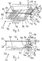
- Fig. 2 shows the upper basket 22 in detail.
- the second portion 34 comprises only a portion 38 of the bottom wall 30, but no part of the side wall 28. This belongs alone to the first portion 32.
- the first portion 32 includes the remaining part 40 of the bottom wall 30 and all side walls 28 and a also perpendicularly extending partition wall 42. This delimits the part 40 of the bottom wall to the second portion 34 toward.
- the bottom wall 30 contains support structures 41 for simplified or improved storage of ware 10.
- the two-part bottom wall 30 is in Fig. 2 hatched shown.
- Their section 38 is designed to be movable relative to the remaining part 40 or the remainder of the upper basket 22, that is to say the first partial area 32.
- the mobility consists here in a height adjustment in the direction of the vertical 14th Fig. 2 shows the second portion 34 shown in solid lines in a first position A.
- the locking of the second portion 34 and the portion 38 of the bottom wall 30 on the first portion 32, in particular the side wall 28 and the partition wall 42, in or the adjustment between the positions AC takes place by hooks, not shown, latching, Snap-on, clamped connections or similar.
- the section 38 can be easily changed between the positions A - C by an operator, not shown.
- the section 38 has in the position A to an altitude H 2 , which lies above an altitude H 0 of the remaining part 40 of the bottom wall 30.
- the altitudes H 0.2 refer to different positions in the direction of the vertical 14th
- Fig. 1 As in Fig. 1 can be seen, the positioning of the section 38 in the height H 2 in the upper region 20, so in the upper basket 22 space for particularly high items to be washed 10, which is mounted in the lower basket 18. Nevertheless, the section 38 can continue to be used to 10 above the elevated items to be washed 10 further items, eg flat cutlery, store on the section 38. The space above the particularly high items to be washed 10 can therefore continue to be used for items 10.
- the second portion 34 in the form of section 38 may, in Fig. 2 indicated by dashes, along the arrow 14 in positions B or C or the altitudes H 1 or H 0 are spent. Then there is less height space available in the dishwasher 2 for items to be washed 10 in the lower basket 18, but more height space is available for items 10 to be deposited on the portion 38. Especially in the position C results in a nearly flat entire bottom wall 30, since now the section 38 and the remaining part 40 have the same altitude H 0 . In this position, for example, in an alternative embodiment, the partition wall 42 can be removed. This results in a top basket 22 with approximately the same floor space for crockery as that in a conventional upper basket.
- Fig. 2 also indicates an upper basket shower or a rotatably mounted spray arm as an exemplary sprayer 44, which is associated with the upper basket 22 to apply this with not shown wash liquor.
- the spray device 44 is preferably coupled to the underside of the fixed first portion 32 of the bottom wall 30.
- the spraying device 44 is in the direction of the arrow 46, ie in the transverse direction of the dishwasher 2 to the left or right, ie away from or onto the second subarea 34 too displaceable. This can ensure that the spraying device with respect to the fixed first Subarea 32 can be aligned, in particular, for example, on the center, when the second, movable portion 34 has been brought into an altitude with height distance to the first portion 32.
- the second portion 34 in the form of the portion 38 of the bottom wall 30 is adjustable in height so that the portion 38 in each of the positions A - C respectively assumes the same inclination to a surface or horizontal 48, here always parallel to this.
- the portion 38 may always occupy the same inclination relative to the horizontal in all positions AC.
- the section 38 occupies different inclinations with respect to the horizontal 48 in different positions AC.
- the entire bottom wall 30, that is the section 38 and the remaining part 40 together, covers in all the positions A - C the entire base area of the upper basket 22 bounded by the side wall 28.
- Fig. 3 shows an alternative embodiment of an upper basket 22 in plan view from the front side 4 ago.
- the second portion 34 here comprises a first wing 50a, which is attached via a pivot 52a to the bottom wall 30 of the first portion 32 and the part 40 thereof.
- the second portion 34 also includes a second wing 50b, which in turn is supported by a second pivot 52b on the first wing 52a.
- the first wing 50a forms a partition 42
- the second wing 50b forms a portion 38 of the bottom wall 30 at an altitude H 1 .
- the entire bottom wall 30, ie the portion 38 together with the remaining part 40 now covers in contrast to the top no longer the entire, limited by the side wall 28 base of the upper basket 22. Rather, a gap 53 remains in the second portion 34 in the upper basket 22, the allows a complete passage of items to be washed 10 through the upper basket 22.
- both wings 50a, b By pivoting the two wings 50a, b in the direction of the arrow 54, they reach position B, in FIG Fig. 3 drawn dashed. Both wings 50 a, b together then form the portion 38 of the bottom wall 30, which lies at the same height H 0 of the remaining part 40 of the bottom wall 30.
- the bottom wall 30 again fills the entire space between the wall parts of the side wall 28 completely. In both positions A and B can be placed on the portion 38 of the bottom wall 30 again 10 items (not shown).
- Fig. 4 shows a further alternative embodiment of an upper basket 22.
- the second subarea has two wings 50a, b, which, however, are connected to the first subarea 32 via a respective rotary joint 52a, b.
- the wings 50a, b are connected to each other, for example via a slot guide 56.
- Fig. 4 1 shows a position A in which the wing 50b forms a section 38 of the bottom wall 30 and the wing 50a forms a partition wall 42.
- the second portion 34 reaches the position B.
- the respective ends of the wings 50a, b opposite the pivot joints 52a, b are guided over the illustrated slot guide 56 during pivoting.
- the wings 50a, b change their roles: The wing 50a form the section 38, the wing 50b, however, no partition, but a part of the side wall 28. So both wings 50a, b fulfill a double task in both positions A, B.
- the second portion 34 includes not only a portion of the bottom wall 30, but also a portion of the side wall 28. In position A so that the partition wall 42 also simultaneously a side wall 28. In place of the slot guide may possibly also a joint or the like be appropriate.
- the wings 50a, b are not permanently connected via a slot guide 56, but are connectable only in the positions A and B.
- appropriate clips, notches or the like are unhooked, the wings 50a, b pivoted along the arrow 58 and hooked together again in the position B.
Landscapes
- Washing And Drying Of Tableware (AREA)
Priority Applications (1)
| Application Number | Priority Date | Filing Date | Title |
|---|---|---|---|
| PL12155570T PL2494908T3 (pl) | 2011-03-02 | 2012-02-15 | Zmywarka do naczyń z przestawnym górnym koszem |
Applications Claiming Priority (1)
| Application Number | Priority Date | Filing Date | Title |
|---|---|---|---|
| DE102011004951A DE102011004951A1 (de) | 2011-03-02 | 2011-03-02 | Geschirrspülmaschine mit verstellbarem Oberkorb |
Publications (3)
| Publication Number | Publication Date |
|---|---|
| EP2494908A2 true EP2494908A2 (fr) | 2012-09-05 |
| EP2494908A3 EP2494908A3 (fr) | 2013-06-05 |
| EP2494908B1 EP2494908B1 (fr) | 2015-01-21 |
Family
ID=45655828
Family Applications (1)
| Application Number | Title | Priority Date | Filing Date |
|---|---|---|---|
| EP12155570.0A Active EP2494908B1 (fr) | 2011-03-02 | 2012-02-15 | Lave-vaisselle doté d'un panier supérieur réglable |
Country Status (4)
| Country | Link |
|---|---|
| US (1) | US9289109B2 (fr) |
| EP (1) | EP2494908B1 (fr) |
| DE (1) | DE102011004951A1 (fr) |
| PL (1) | PL2494908T3 (fr) |
Cited By (1)
| Publication number | Priority date | Publication date | Assignee | Title |
|---|---|---|---|---|
| WO2016078892A1 (fr) * | 2014-11-17 | 2016-05-26 | BSH Hausgeräte GmbH | Compartiment de rangement d'articles à laver et lave-vaisselle ménager |
Families Citing this family (8)
| Publication number | Priority date | Publication date | Assignee | Title |
|---|---|---|---|---|
| JP6839887B2 (ja) * | 2015-03-19 | 2021-03-10 | パナソニックIpマネジメント株式会社 | 食器乾燥庫 |
| US10368718B2 (en) | 2016-12-16 | 2019-08-06 | Midea Group Co., Ltd. | Dishwater with modular docking |
| US10849480B2 (en) | 2016-12-16 | 2020-12-01 | Midea Group Co., Ltd. | Dishwasher including spray basket with integrated external sprayer |
| US10561296B2 (en) | 2016-12-16 | 2020-02-18 | Midea Group Co., Ltd. | Dishwasher with dock detection |
| US10342409B2 (en) | 2016-12-16 | 2019-07-09 | Midea Group Co., Ltd. | Dishwasher with drinkware spray container |
| US10517458B2 (en) | 2016-12-16 | 2019-12-31 | Midea Group Co., Ltd. | Dishwasher including silverware basket with integrated interior sprayer |
| US11147430B2 (en) | 2019-03-27 | 2021-10-19 | Midea Group Co., Ltd. | Dishwasher including rack corner sprayers |
| US11712148B2 (en) * | 2021-08-13 | 2023-08-01 | Haier Us Appliance Solutions, Inc. | Collapsible rack for dishwasher appliance |
Citations (3)
| Publication number | Priority date | Publication date | Assignee | Title |
|---|---|---|---|---|
| DE20019480U1 (de) | 1999-11-29 | 2001-02-15 | Electrolux Zanussi S.P.A., Pordenone | Geschirrspülmaschine mit einem an die zu spülenden Geschirrteile anpassbaren Fassungsvermögen |
| EP1458276B1 (fr) | 2001-12-19 | 2010-04-28 | BSH Bosch und Siemens Hausgeräte GmbH | Dispositif pour commander le processus de lavage de vaisselle dans un lave-vaisselle |
| US20100314977A1 (en) | 2009-06-11 | 2010-12-16 | Mallory Brian L | Adjustable upper dishwasher rack |
Family Cites Families (9)
| Publication number | Priority date | Publication date | Assignee | Title |
|---|---|---|---|---|
| FR96123E (fr) * | 1967-11-24 | 1972-05-19 | Gen Electric | Machines a laver la vaisselle a ouverture frontale avec systeme perfectionné de paniers. |
| JP2528068Y2 (ja) * | 1992-01-29 | 1997-03-05 | 三洋電機株式会社 | 食器乾燥機 |
| US5944037A (en) * | 1996-10-16 | 1999-08-31 | Samsung Electronics Co., Ltd. | Water spray apparatus for tableware washing machine |
| JP2005118210A (ja) * | 2003-10-15 | 2005-05-12 | Toshiba Corp | 食器洗浄機 |
| DE102006055352A1 (de) * | 2006-11-23 | 2008-05-29 | BSH Bosch und Siemens Hausgeräte GmbH | Besteckkorb für eine Geschirrspülmaschine und Geschirrspülmaschine |
| KR101318361B1 (ko) * | 2006-12-29 | 2013-10-15 | 엘지전자 주식회사 | 식기세척기 |
| KR100879573B1 (ko) * | 2007-08-10 | 2009-01-22 | 엘지전자 주식회사 | 식기 세척기용 랙 및 이를 구비한 컴팩트형 식기세척기 |
| US7959744B2 (en) * | 2007-09-19 | 2011-06-14 | Whirlpool Corporation | Dishwasher with targeted sensing and washing |
| US9167953B2 (en) * | 2011-01-07 | 2015-10-27 | Electrolux Home Products, Inc. | Dishwasher with a manifold assembly configured to attach a manifold to a dish rack and associated method |
-
2011
- 2011-03-02 DE DE102011004951A patent/DE102011004951A1/de not_active Withdrawn
-
2012
- 2012-02-15 PL PL12155570T patent/PL2494908T3/pl unknown
- 2012-02-15 EP EP12155570.0A patent/EP2494908B1/fr active Active
- 2012-02-20 US US13/400,142 patent/US9289109B2/en not_active Expired - Fee Related
Patent Citations (3)
| Publication number | Priority date | Publication date | Assignee | Title |
|---|---|---|---|---|
| DE20019480U1 (de) | 1999-11-29 | 2001-02-15 | Electrolux Zanussi S.P.A., Pordenone | Geschirrspülmaschine mit einem an die zu spülenden Geschirrteile anpassbaren Fassungsvermögen |
| EP1458276B1 (fr) | 2001-12-19 | 2010-04-28 | BSH Bosch und Siemens Hausgeräte GmbH | Dispositif pour commander le processus de lavage de vaisselle dans un lave-vaisselle |
| US20100314977A1 (en) | 2009-06-11 | 2010-12-16 | Mallory Brian L | Adjustable upper dishwasher rack |
Cited By (3)
| Publication number | Priority date | Publication date | Assignee | Title |
|---|---|---|---|---|
| WO2016078892A1 (fr) * | 2014-11-17 | 2016-05-26 | BSH Hausgeräte GmbH | Compartiment de rangement d'articles à laver et lave-vaisselle ménager |
| CN107105962A (zh) * | 2014-11-17 | 2017-08-29 | Bsh家用电器有限公司 | 冲洗物容纳部和家用洗碗机 |
| CN107105962B (zh) * | 2014-11-17 | 2019-05-03 | Bsh家用电器有限公司 | 冲洗物容纳部和家用洗碗机 |
Also Published As
| Publication number | Publication date |
|---|---|
| EP2494908B1 (fr) | 2015-01-21 |
| PL2494908T3 (pl) | 2015-06-30 |
| US9289109B2 (en) | 2016-03-22 |
| EP2494908A3 (fr) | 2013-06-05 |
| DE102011004951A1 (de) | 2012-09-06 |
| US20120222711A1 (en) | 2012-09-06 |
Similar Documents
| Publication | Publication Date | Title |
|---|---|---|
| EP2494908B1 (fr) | Lave-vaisselle doté d'un panier supérieur réglable | |
| EP2096976B1 (fr) | Panier à couverts pour lave-vaisselle et lave-vaisselle approprié | |
| DE102013112714B4 (de) | Geschirrspüler | |
| DE102011081774B4 (de) | Geschirrspülmaschine mit einer zur Halterung von kleinen Spülgutstücken, insbesondere Besteckteilen, vorgesehenen Aufnahmestruktur | |
| DE10164505A1 (de) | Besteckkorb für eine Geschirrspülmaschine | |
| EP2741655A1 (fr) | Machine à laver la vaisselle avec au moins une structure de réception de la vaisselle dotée d'indications de placement | |
| DE69009491T2 (de) | Geschirrspülmaschine mit einer senkrecht beweglichen tür. | |
| EP4076126B1 (fr) | Égouttoir à vaisselle | |
| DE60130882T2 (de) | Geschirrspülmaschine mit einem zusätzlichen Besteckkorb | |
| WO2016102234A1 (fr) | Panier inférieur pour lave-vaisselle domestique à soulèvement de panier inférieur | |
| DE102012016762B4 (de) | Geschirrspülmaschine | |
| EP0084586A1 (fr) | Meuble intégré pour cuisine | |
| EP1965686A1 (fr) | Lave-vaisselle avec agencement amélioré du dispositif d'addition situé dans la porte | |
| EP4085816B1 (fr) | Dispositif de protection contre les projections, dispositif de réception d'articles à laver et lave-vaisselle domestique | |
| DE102012202786A1 (de) | Geschirrspülmaschine mit einem einen nach unten abschwenkbaren Bodenbereich aufweisenden Oberkorb | |
| EP2494907B1 (fr) | Lave-vaisselle doté d'un panier supérieur réglable | |
| DE102005058665B4 (de) | Geschirrkorb mit lösbaren Spülgutablagen | |
| DE29608871U1 (de) | Geschirrspülmaschine mit Geschirrkörben zum Anordnen von zu spülendem Gut | |
| DE102008055021A1 (de) | Geschirrspülmaschine sowie Einsatzelement für einen Besteckkorb einer solchen Geschirrspülmaschine | |
| DE10063355A1 (de) | Tür für Haushaltgeräte | |
| DE102011003657A1 (de) | Geschirrablagesysteme für einen Geschirrkorb einer Geschirrspülmaschine | |
| EP2328454A2 (fr) | Lave-vaisselle à encastrer dans un placard | |
| DE102007048198A1 (de) | Korb für eine Geschirrspülmaschine | |
| DE102019213112A1 (de) | Haushaltsgeschirrspülmaschine mit einer ein oberes, separat aufschwenkbares Türteil aufweisenden Gesamttür | |
| DE19954471A1 (de) | Geschirrspülmaschine mit einem Spülbehälter |
Legal Events
| Date | Code | Title | Description |
|---|---|---|---|
| PUAI | Public reference made under article 153(3) epc to a published international application that has entered the european phase |
Free format text: ORIGINAL CODE: 0009012 |
|
| AK | Designated contracting states |
Kind code of ref document: A2 Designated state(s): AL AT BE BG CH CY CZ DE DK EE ES FI FR GB GR HR HU IE IS IT LI LT LU LV MC MK MT NL NO PL PT RO RS SE SI SK SM TR |
|
| AX | Request for extension of the european patent |
Extension state: BA ME |
|
| PUAL | Search report despatched |
Free format text: ORIGINAL CODE: 0009013 |
|
| AK | Designated contracting states |
Kind code of ref document: A3 Designated state(s): AL AT BE BG CH CY CZ DE DK EE ES FI FR GB GR HR HU IE IS IT LI LT LU LV MC MK MT NL NO PL PT RO RS SE SI SK SM TR |
|
| AX | Request for extension of the european patent |
Extension state: BA ME |
|
| RIC1 | Information provided on ipc code assigned before grant |
Ipc: A47L 15/50 20060101AFI20130430BHEP |
|
| 17P | Request for examination filed |
Effective date: 20131205 |
|
| RBV | Designated contracting states (corrected) |
Designated state(s): AL AT BE BG CH CY CZ DE DK EE ES FI FR GB GR HR HU IE IS IT LI LT LU LV MC MK MT NL NO PL PT RO RS SE SI SK SM TR |
|
| GRAP | Despatch of communication of intention to grant a patent |
Free format text: ORIGINAL CODE: EPIDOSNIGR1 |
|
| INTG | Intention to grant announced |
Effective date: 20141008 |
|
| GRAS | Grant fee paid |
Free format text: ORIGINAL CODE: EPIDOSNIGR3 |
|
| GRAA | (expected) grant |
Free format text: ORIGINAL CODE: 0009210 |
|
| AK | Designated contracting states |
Kind code of ref document: B1 Designated state(s): AL AT BE BG CH CY CZ DE DK EE ES FI FR GB GR HR HU IE IS IT LI LT LU LV MC MK MT NL NO PL PT RO RS SE SI SK SM TR |
|
| REG | Reference to a national code |
Ref country code: GB Ref legal event code: FG4D Free format text: NOT ENGLISH |
|
| REG | Reference to a national code |
Ref country code: CH Ref legal event code: EP |
|
| REG | Reference to a national code |
Ref country code: IE Ref legal event code: FG4D Free format text: LANGUAGE OF EP DOCUMENT: GERMAN |
|
| REG | Reference to a national code |
Ref country code: FR Ref legal event code: PLFP Year of fee payment: 4 |
|
| REG | Reference to a national code |
Ref country code: CH Ref legal event code: PFA Owner name: BSH HAUSGERAETE GMBH, DE Free format text: FORMER OWNER: BSH BOSCH UND SIEMENS HAUSGERAETE GMBH, DE |
|
| REG | Reference to a national code |
Ref country code: DE Ref legal event code: R096 Ref document number: 502012002146 Country of ref document: DE Effective date: 20150305 |
|
| REG | Reference to a national code |
Ref country code: AT Ref legal event code: REF Ref document number: 708783 Country of ref document: AT Kind code of ref document: T Effective date: 20150315 |
|
| RAP2 | Party data changed (patent owner data changed or rights of a patent transferred) |
Owner name: BSH HAUSGERAETE GMBH |
|
| REG | Reference to a national code |
Ref country code: DE Ref legal event code: R081 Ref document number: 502012002146 Country of ref document: DE Owner name: BSH HAUSGERAETE GMBH, DE Free format text: FORMER OWNER: BSH BOSCH UND SIEMENS HAUSGERAETE GMBH, 81739 MUENCHEN, DE Effective date: 20150409 |
|
| REG | Reference to a national code |
Ref country code: NL Ref legal event code: VDEP Effective date: 20150121 |
|
| REG | Reference to a national code |
Ref country code: LT Ref legal event code: MG4D |
|
| PG25 | Lapsed in a contracting state [announced via postgrant information from national office to epo] |
Ref country code: BE Free format text: LAPSE BECAUSE OF NON-PAYMENT OF DUE FEES Effective date: 20150228 |
|
| REG | Reference to a national code |
Ref country code: PL Ref legal event code: T3 |
|
| PG25 | Lapsed in a contracting state [announced via postgrant information from national office to epo] |
Ref country code: ES Free format text: LAPSE BECAUSE OF FAILURE TO SUBMIT A TRANSLATION OF THE DESCRIPTION OR TO PAY THE FEE WITHIN THE PRESCRIBED TIME-LIMIT Effective date: 20150121 Ref country code: HR Free format text: LAPSE BECAUSE OF FAILURE TO SUBMIT A TRANSLATION OF THE DESCRIPTION OR TO PAY THE FEE WITHIN THE PRESCRIBED TIME-LIMIT Effective date: 20150121 Ref country code: NO Free format text: LAPSE BECAUSE OF FAILURE TO SUBMIT A TRANSLATION OF THE DESCRIPTION OR TO PAY THE FEE WITHIN THE PRESCRIBED TIME-LIMIT Effective date: 20150421 Ref country code: FI Free format text: LAPSE BECAUSE OF FAILURE TO SUBMIT A TRANSLATION OF THE DESCRIPTION OR TO PAY THE FEE WITHIN THE PRESCRIBED TIME-LIMIT Effective date: 20150121 Ref country code: BG Free format text: LAPSE BECAUSE OF FAILURE TO SUBMIT A TRANSLATION OF THE DESCRIPTION OR TO PAY THE FEE WITHIN THE PRESCRIBED TIME-LIMIT Effective date: 20150421 Ref country code: LT Free format text: LAPSE BECAUSE OF FAILURE TO SUBMIT A TRANSLATION OF THE DESCRIPTION OR TO PAY THE FEE WITHIN THE PRESCRIBED TIME-LIMIT Effective date: 20150121 Ref country code: SE Free format text: LAPSE BECAUSE OF FAILURE TO SUBMIT A TRANSLATION OF THE DESCRIPTION OR TO PAY THE FEE WITHIN THE PRESCRIBED TIME-LIMIT Effective date: 20150121 |
|
| PG25 | Lapsed in a contracting state [announced via postgrant information from national office to epo] |
Ref country code: RS Free format text: LAPSE BECAUSE OF FAILURE TO SUBMIT A TRANSLATION OF THE DESCRIPTION OR TO PAY THE FEE WITHIN THE PRESCRIBED TIME-LIMIT Effective date: 20150121 Ref country code: GR Free format text: LAPSE BECAUSE OF FAILURE TO SUBMIT A TRANSLATION OF THE DESCRIPTION OR TO PAY THE FEE WITHIN THE PRESCRIBED TIME-LIMIT Effective date: 20150422 Ref country code: NL Free format text: LAPSE BECAUSE OF FAILURE TO SUBMIT A TRANSLATION OF THE DESCRIPTION OR TO PAY THE FEE WITHIN THE PRESCRIBED TIME-LIMIT Effective date: 20150121 Ref country code: LV Free format text: LAPSE BECAUSE OF FAILURE TO SUBMIT A TRANSLATION OF THE DESCRIPTION OR TO PAY THE FEE WITHIN THE PRESCRIBED TIME-LIMIT Effective date: 20150121 Ref country code: IS Free format text: LAPSE BECAUSE OF FAILURE TO SUBMIT A TRANSLATION OF THE DESCRIPTION OR TO PAY THE FEE WITHIN THE PRESCRIBED TIME-LIMIT Effective date: 20150521 |
|
| REG | Reference to a national code |
Ref country code: CH Ref legal event code: PL |
|
| REG | Reference to a national code |
Ref country code: DE Ref legal event code: R097 Ref document number: 502012002146 Country of ref document: DE |
|
| PG25 | Lapsed in a contracting state [announced via postgrant information from national office to epo] |
Ref country code: SK Free format text: LAPSE BECAUSE OF FAILURE TO SUBMIT A TRANSLATION OF THE DESCRIPTION OR TO PAY THE FEE WITHIN THE PRESCRIBED TIME-LIMIT Effective date: 20150121 Ref country code: LI Free format text: LAPSE BECAUSE OF NON-PAYMENT OF DUE FEES Effective date: 20150228 Ref country code: CH Free format text: LAPSE BECAUSE OF NON-PAYMENT OF DUE FEES Effective date: 20150228 Ref country code: CZ Free format text: LAPSE BECAUSE OF FAILURE TO SUBMIT A TRANSLATION OF THE DESCRIPTION OR TO PAY THE FEE WITHIN THE PRESCRIBED TIME-LIMIT Effective date: 20150121 Ref country code: DK Free format text: LAPSE BECAUSE OF FAILURE TO SUBMIT A TRANSLATION OF THE DESCRIPTION OR TO PAY THE FEE WITHIN THE PRESCRIBED TIME-LIMIT Effective date: 20150121 Ref country code: MC Free format text: LAPSE BECAUSE OF FAILURE TO SUBMIT A TRANSLATION OF THE DESCRIPTION OR TO PAY THE FEE WITHIN THE PRESCRIBED TIME-LIMIT Effective date: 20150121 Ref country code: RO Free format text: LAPSE BECAUSE OF FAILURE TO SUBMIT A TRANSLATION OF THE DESCRIPTION OR TO PAY THE FEE WITHIN THE PRESCRIBED TIME-LIMIT Effective date: 20150121 Ref country code: EE Free format text: LAPSE BECAUSE OF FAILURE TO SUBMIT A TRANSLATION OF THE DESCRIPTION OR TO PAY THE FEE WITHIN THE PRESCRIBED TIME-LIMIT Effective date: 20150121 |
|
| REG | Reference to a national code |
Ref country code: IE Ref legal event code: MM4A |
|
| PLBE | No opposition filed within time limit |
Free format text: ORIGINAL CODE: 0009261 |
|
| REG | Reference to a national code |
Ref country code: FR Ref legal event code: CD Owner name: BSH HAUSGERATE GMBH, DE Effective date: 20151022 |
|
| STAA | Information on the status of an ep patent application or granted ep patent |
Free format text: STATUS: NO OPPOSITION FILED WITHIN TIME LIMIT |
|
| 26N | No opposition filed |
Effective date: 20151022 |
|
| PG25 | Lapsed in a contracting state [announced via postgrant information from national office to epo] |
Ref country code: IT Free format text: LAPSE BECAUSE OF FAILURE TO SUBMIT A TRANSLATION OF THE DESCRIPTION OR TO PAY THE FEE WITHIN THE PRESCRIBED TIME-LIMIT Effective date: 20150121 |
|
| PG25 | Lapsed in a contracting state [announced via postgrant information from national office to epo] |
Ref country code: IE Free format text: LAPSE BECAUSE OF NON-PAYMENT OF DUE FEES Effective date: 20150215 |
|
| REG | Reference to a national code |
Ref country code: FR Ref legal event code: PLFP Year of fee payment: 5 |
|
| PG25 | Lapsed in a contracting state [announced via postgrant information from national office to epo] |
Ref country code: SI Free format text: LAPSE BECAUSE OF FAILURE TO SUBMIT A TRANSLATION OF THE DESCRIPTION OR TO PAY THE FEE WITHIN THE PRESCRIBED TIME-LIMIT Effective date: 20150121 |
|
| GBPC | Gb: european patent ceased through non-payment of renewal fee |
Effective date: 20160215 |
|
| PG25 | Lapsed in a contracting state [announced via postgrant information from national office to epo] |
Ref country code: MT Free format text: LAPSE BECAUSE OF FAILURE TO SUBMIT A TRANSLATION OF THE DESCRIPTION OR TO PAY THE FEE WITHIN THE PRESCRIBED TIME-LIMIT Effective date: 20150121 |
|
| PG25 | Lapsed in a contracting state [announced via postgrant information from national office to epo] |
Ref country code: GB Free format text: LAPSE BECAUSE OF NON-PAYMENT OF DUE FEES Effective date: 20160215 |
|
| REG | Reference to a national code |
Ref country code: FR Ref legal event code: PLFP Year of fee payment: 6 |
|
| PG25 | Lapsed in a contracting state [announced via postgrant information from national office to epo] |
Ref country code: SM Free format text: LAPSE BECAUSE OF FAILURE TO SUBMIT A TRANSLATION OF THE DESCRIPTION OR TO PAY THE FEE WITHIN THE PRESCRIBED TIME-LIMIT Effective date: 20150121 Ref country code: HU Free format text: LAPSE BECAUSE OF FAILURE TO SUBMIT A TRANSLATION OF THE DESCRIPTION OR TO PAY THE FEE WITHIN THE PRESCRIBED TIME-LIMIT; INVALID AB INITIO Effective date: 20120215 |
|
| PG25 | Lapsed in a contracting state [announced via postgrant information from national office to epo] |
Ref country code: CY Free format text: LAPSE BECAUSE OF FAILURE TO SUBMIT A TRANSLATION OF THE DESCRIPTION OR TO PAY THE FEE WITHIN THE PRESCRIBED TIME-LIMIT Effective date: 20150121 |
|
| PG25 | Lapsed in a contracting state [announced via postgrant information from national office to epo] |
Ref country code: PT Free format text: LAPSE BECAUSE OF FAILURE TO SUBMIT A TRANSLATION OF THE DESCRIPTION OR TO PAY THE FEE WITHIN THE PRESCRIBED TIME-LIMIT Effective date: 20150521 |
|
| PG25 | Lapsed in a contracting state [announced via postgrant information from national office to epo] |
Ref country code: LU Free format text: LAPSE BECAUSE OF NON-PAYMENT OF DUE FEES Effective date: 20150215 |
|
| REG | Reference to a national code |
Ref country code: FR Ref legal event code: PLFP Year of fee payment: 7 |
|
| REG | Reference to a national code |
Ref country code: AT Ref legal event code: MM01 Ref document number: 708783 Country of ref document: AT Kind code of ref document: T Effective date: 20170215 |
|
| PG25 | Lapsed in a contracting state [announced via postgrant information from national office to epo] |
Ref country code: AT Free format text: LAPSE BECAUSE OF NON-PAYMENT OF DUE FEES Effective date: 20170215 |
|
| PG25 | Lapsed in a contracting state [announced via postgrant information from national office to epo] |
Ref country code: MK Free format text: LAPSE BECAUSE OF FAILURE TO SUBMIT A TRANSLATION OF THE DESCRIPTION OR TO PAY THE FEE WITHIN THE PRESCRIBED TIME-LIMIT Effective date: 20150121 |
|
| PG25 | Lapsed in a contracting state [announced via postgrant information from national office to epo] |
Ref country code: AL Free format text: LAPSE BECAUSE OF FAILURE TO SUBMIT A TRANSLATION OF THE DESCRIPTION OR TO PAY THE FEE WITHIN THE PRESCRIBED TIME-LIMIT Effective date: 20150121 |
|
| REG | Reference to a national code |
Ref country code: DE Ref legal event code: R084 Ref document number: 502012002146 Country of ref document: DE |
|
| PGFP | Annual fee paid to national office [announced via postgrant information from national office to epo] |
Ref country code: PL Payment date: 20250131 Year of fee payment: 14 |
|
| PGFP | Annual fee paid to national office [announced via postgrant information from national office to epo] |
Ref country code: DE Payment date: 20260228 Year of fee payment: 15 |
|
| PGFP | Annual fee paid to national office [announced via postgrant information from national office to epo] |
Ref country code: FR Payment date: 20260219 Year of fee payment: 15 |
|
| PGFP | Annual fee paid to national office [announced via postgrant information from national office to epo] |
Ref country code: TR Payment date: 20260212 Year of fee payment: 15 |