EP2495080B1 - Outil de coupe doté d'une lame en diamant cristallin fin - Google Patents
Outil de coupe doté d'une lame en diamant cristallin fin Download PDFInfo
- Publication number
- EP2495080B1 EP2495080B1 EP20110001693 EP11001693A EP2495080B1 EP 2495080 B1 EP2495080 B1 EP 2495080B1 EP 20110001693 EP20110001693 EP 20110001693 EP 11001693 A EP11001693 A EP 11001693A EP 2495080 B1 EP2495080 B1 EP 2495080B1
- Authority
- EP
- European Patent Office
- Prior art keywords
- layer
- cutting tool
- crystalline diamond
- cutting edge
- fine crystalline
- Prior art date
- Legal status (The legal status is an assumption and is not a legal conclusion. Google has not performed a legal analysis and makes no representation as to the accuracy of the status listed.)
- Active
Links
Images



Classifications
-
- B—PERFORMING OPERATIONS; TRANSPORTING
- B26—HAND CUTTING TOOLS; CUTTING; SEVERING
- B26B—HAND-HELD CUTTING TOOLS NOT OTHERWISE PROVIDED FOR
- B26B21/00—Razors of the open or knife type; Safety razors or other shaving implements of the planing type; Hair-trimming devices involving a razor-blade; Equipment therefor
- B26B21/54—Razor-blades
- B26B21/58—Razor-blades characterised by the material
-
- B—PERFORMING OPERATIONS; TRANSPORTING
- B26—HAND CUTTING TOOLS; CUTTING; SEVERING
- B26B—HAND-HELD CUTTING TOOLS NOT OTHERWISE PROVIDED FOR
- B26B21/00—Razors of the open or knife type; Safety razors or other shaving implements of the planing type; Hair-trimming devices involving a razor-blade; Equipment therefor
- B26B21/54—Razor-blades
- B26B21/58—Razor-blades characterised by the material
- B26B21/60—Razor-blades characterised by the material by the coating material
Definitions
- the present invention relates to a cutting tool, in particular in the form of a razor blade, a scalpel, a knife, a machine knife, a pair of scissors, etc., which has a synthetic diamond layer with a cutting edge.
- the diamond layer consists of fine crystalline diamond.
- Cutting tools such as knives and scalpels having diamond layers have been known in the prior art for some time. These cutting tools can be completely formed from a diamond layer (full diamond blade), as well as the possibility can be given that a synthetic diamond layer is applied to a substrate suitable for this purpose. In most cases, the cutting edge of the cutting tool is formed in the diamond layer, since diamond is the hardest known Material is.
- These blades are distinguished from, for example, steel blades by a higher cutting ability (sharpness) and a higher cutting durability (life, service life).
- the diamond materials that are used for the blades known from the prior art are either polycrystalline diamond materials, on the other hand, the use of single-crystal diamond is possible.
- single-crystal diamond is extremely difficult to produce and process, on the other hand it is very expensive, so that it is unsuitable for use in mass products such as razor blades.
- Polycrystalline diamond layers are characterized by a clearly heterogeneous distribution of the size of the crystalline domains.
- the sizes of the crystalline regions in polycrystalline diamond vary over several orders of magnitude.
- at least 50% of the crystallites are present with an average size between 2 and 100 ⁇ m.
- Such a polycrystalline diamond layer is thus very heterogeneous, but inexpensive to produce.
- polycrystalline diamond layers on the growth side have high surface roughness on. This is usually about rms> 1 ⁇ m.
- polycrystalline diamond layers in the transverse fracture have a columnar structure, ie the grain boundaries are substantially perpendicular to the substrate surface. Since the grain boundary represents a macroscopic defect, it acts like a predetermined breaking point.
- polycrystalline diamond layers contain a large number of these predetermined breaking points and are therefore very susceptible to breakage. For example, the bending stress ⁇ 0 for polycrystalline layers is about 1/10 that of monocrystalline diamond.
- the inner cutting edge represents the point at which the tapering flanks of the core converge to form an inner (cutting) edge.
- the fine crystalline diamond layer which is applied to the core, follows the course of the tapered Edges, wherein also forms a cutting edge in the fine crystalline diamond layer, the "outer" cutting edge.
- the outer cutting edge forms the actual cutting edge of the cutting tool.
- finely crystalline diamond is understood to mean a diamond layer, the crystalline domains having an average particle size d 50 of ⁇ 100 nm. By this is meant that at least 50% of the crystallites have each dimension of a single crystallite ⁇ 100 nm.
- the fine-crystalline diamond layer is thus characterized by an extremely high homogeneity of the crystallites.
- the bending stress ⁇ 0 is determined by statistical evaluation of fracture tests, eg in the B3B load test determined according to the above references. It is defined as the breaking stress at which the probability of breakage is 63%.
- the cutting tools according to the invention can be formed symmetrically or asymmetrically with respect to the cutting edge.
- the cutting tool may have a chamfer, i. a second angle at the cutting edge.
- This chamfer can e.g. be formed in the core and be continued by uniform coating with the fine crystalline diamond layer to the surface of the cutting tool, in addition to or alternatively, however, also the formation of the bevel in the fine crystalline diamond layer is possible.
- the layer thickness y of the fine-crystalline diamond layer is between 1 and 500 ⁇ m, preferably between 1 and 50 ⁇ m, particularly preferably between 2 and 10 microns.
- the layer thickness y of the fine-crystalline diamond layer is determined in the region of the flanks of the core forming the cutting edge and orthogonal to this flank.
- the fine-crystalline diamond layer has a layer thickness x projected onto the inner cutting edge, with the proviso that 0.1 ⁇ y / x ⁇ 0.6, preferably 0.12 ⁇ y / x ⁇ 0.5 , particularly preferably 0.13 ⁇ y / x ⁇ 0.25.
- the layer thickness x corresponds to the smallest distance between the inner cutting edge of the core and the outer cutting edge formed in the fine crystalline diamond layer.
- the layer thickness is measured in the direction of the normal plane at the tangent of the outer cutting edge.
- the layer thickness x therefore corresponds to the distance of the outer cutting edge of the fine-grained diamond layer and the inner cutting edge of the core.
- the average particle size d 50 of the finely crystalline diamond is preferably between 5 and 100 nm, particularly preferably between 10 and 70 nm.
- Preferred cutting angles ⁇ are between 10 ° and 40 °, preferably between 10 ° and 30 °, especially between 15 ° and 25 °.
- the cutting angle ⁇ is determined by the finely crystalline diamond layer, ie defined by the angle at which the outer surfaces of the cutting tool converge on the outer cutting edge.
- a preferred proportion of sp and sp 2 bonds of the finely crystalline diamond layer is between 0.5 and 10%, preferably between 2 and 9%, particularly preferably between 3 and 8%.
- a higher sp 2 content causes the modulus of elasticity of the fine-grained diamond layer to be slightly lowered.
- the hardness of this material also decreases.
- the fine-crystalline diamond layers become more flexible and elastic overall and can better adapt to the material to be cut or the contour of the material to be cut.
- an optimal adaptation to the core material is ensured, which reduces the likelihood of delamination of the fine crystalline diamond layer.
- Advantageous core materials are selected from the group consisting of metals such as titanium, nickel, chromium, niobium, tungsten, tantalum, molybdenum, vanadium, platinum, iron-containing materials such as steel and / or germanium; from carbon and / or nitrogen or boron-containing ceramics, such as silicon carbide, silicon nitride, boron nitride, tantalum carbide, tungsten carbide, molybdenum carbide, titanium nitrides, TiAlN, TiCN and / or TiB 2 , glass ceramics; Composites of ceramic materials in a metallic matrix (cermets); Hard metals; sintered carbide carbides such as cobalt or nickel bonded tungsten carbides or titanium carbides; Silicon, glass or sapphire; and monocrystalline or polycrystalline diamond and / or diamond-like carbon layers.
- metals such as titanium, nickel, chromium, niobium, tungsten, tantalum, molybdenum,
- the core is formed, for example, from common metals or alloys, it is also provided that the core may also be formed from single or polycrystalline diamond or diamond-like carbon materials can. In this sense, one could also speak of a "full diamond blade" in the latter embodiment, but with two different diamond materials are used.
- the average grain diameter d 50 of the fine-grained diamond layer forming the outer blade is smaller than the average grain diameter d 50 of the core material.
- the bending fracture stress ⁇ 0 of the diamond layer is> 2 GPa, preferably> 4 GPa, particularly preferably> 5 GPa.
- ⁇ 0 is defined as above.
- the modulus of elasticity of the diamond layer is ⁇ 1.200 GPa, preferably ⁇ 900, particularly preferably ⁇ 750 GPa.
- a further preferred embodiment provides that the ratio r 2 / d 50 of the radius of curvature of the diamond layer at the outer cutting edge to the mean grain size of the fine crystalline diamond is between 0.03 and 20, preferably between 0.05 and 15, particularly preferably between 0.5 and 10 lies.
- the gradient of the average grain size of the fine-crystalline diamond measured in the direction of the thickness y of the fine-crystalline diamond layer is ⁇ 300%, preferably ⁇ 100%, particularly preferably ⁇ 50%.
- This embodiment provides that the mean grain size diameter of the fine-grained domains of the diamond layer through the entire layer thickness is relatively uniform to particularly is evenly distributed, ie the grain sizes are approximately the same size on one side of the diamond layer as on the other side of the diamond layer; Of course, it is particularly advantageous in this case for a virtually complete or complete complete homogeneity of the finely crystalline domains of the diamond layer.
- the gradient is determined by determining the average grain size diameter d 50 on one side of the diamond layer and relating it to the average grain size diameter on the opposite side of the diamond layer.
- Particularly preferred embodiments provide that, for example, between the core and the fine-crystalline diamond layer, at least one first adhesion promoter layer, preferably of silicon carbide, silicon nitride, tungsten, titanium or silicon, is arranged.
- the first adhesion promoter layer thereby increases the strength of the mechanical bond between the core and the fine-crystalline diamond layer.
- the fine-crystalline diamond layer at least one second adhesion promoter layer, preferably of Cr, Pt, Ti or W, and thereon a sliding layer, in particular a polymer layer, preferably a PTFE layer , a carbon layer, preferably a graphite layer and / or a DLC layer, is applied.
- the second adhesion promoter layer also serves to better bond the sliding layer to the fine crystalline diamond layer.
- carbon layers, graphite or DLC layers are used as a sliding layer, can also be dispensed with the second adhesion promoter layer, since a direct bonding of the carbon layers to the fine crystalline diamond layer is possible.
- the sliding layer serves to minimize friction between the cutting tool and cutting material. Likewise, a minimization of dirt adhesion, avoidance of cutting dust and a reduction of the cutting forces is achieved.
- the diamond layer is preferably very smooth, ie has an average surface roughness of R A ⁇ 5 .mu.m, preferably ⁇ 2 .mu.m, more preferably ⁇ 1 .mu.m. This makes an additional mechanical polishing of the grown diamond surface superfluous.
- a further preferred embodiment of the cutting tool provides that the cutting tool has notches or cuts at regular intervals, preferably at regular intervals of less than 10 mm. These notches in the blade or the cuts of the blade to the fuselage can be formed at regular intervals of less than 10 mm. Preferred distances are for example between 5 and 9 mm. These indentations allow the blade to be guided relative to the material to be cut, thus stabilizing the cutting tool during the cutting process.
- a further preferred embodiment provides that the crystallites of the finely crystalline diamond layer are preferably grown in the ⁇ 100>, ⁇ 110> and / or ⁇ 111> direction, ie a texture is present. This can result from the manufacturing process, in which the growth rate of certain crystal directions can be specifically favored. This anisotropic texture of the crystallites also positively affects the mechanical properties.
- the cutting tool is designed as a blade, knife blade, razor blade, scalpel, knife, machine knife, scissors or machine shears or can be used as such. It is also possible that the cutting tool is designed as a shaving system, ie as a head with a plurality of razor blades or can be used as such. All razor blades are designed as cutting tools according to the invention.
- Ion etching is sharpened and optionally smoothed.
- step c) the deposition of the fine crystalline diamond layer can be carried out, for example, in the manner given in the following example.
- the fine-crystalline diamond films are produced, for example, by means of a "hot-wire CVD process".
- a gas phase consisting of, for example 1 to 5 vol .-% CH 4 and 95 to 99 vol .-% hydrogen activated.
- the wire temperature is, for example, in a range of 1,800 ° C to 2,400 ° C.
- a substrate temperature of 600 ° C to 900 ° C is set.
- the pressure of the gas atmosphere is between 3 mbar and 30 mbar. In this case, the fine-grained diamond layer is deposited on the substrate.
- At least one first adhesion promoter layer can be deposited on the core before step b) and the seed crystals deposited on the at least one first adhesion promoter layer.
- the adhesion promoter layer can simultaneously serve as a diffusion barrier for the subsequent CVD growth step and protect the core material against degradation by the aggressive environmental conditions.
- At least one second adhesion promoter layer preferably of Cr, Pt, Ti or W, and thereon a sliding layer, in particular a polymer layer, preferably a PTFE layer, a carbon layer, preferably a graphite layer, are present on the fine crystalline diamond layer and / or a DLC layer.
- a sliding layer in particular a polymer layer, preferably a PTFE layer, a carbon layer, preferably a graphite layer
- the second adhesion promoter layer also, since a direct bonding of the carbon layers to the fine crystalline diamond layer is possible.
- a further embodiment provides that after completion of the aforementioned method notches are introduced into the cutting tool described above.
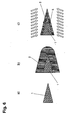
- FIG. 1 shows three different variants of blades, each made entirely of diamond.
- FIG. 1a shows a blade consisting of single crystal diamond.
- the rounding radius r of the cutting edge is indicated (detail D).
- FIG. 1b shows by default known in the art Volldiamantklingen based on polycrystalline diamond material.
- FIG. 1b the polymorphism of the arranged crystallite domains of the polycrystalline material is shown.
- Crystals from the blade in particular in the area preferably along grain boundaries of the cutting edge (see detail A) break out, so that the blade has, for example, already on first use an increased Schartmaschine. This results in a very inhomogeneous cutting edge, which significantly affects the cutting ability and the cutting edge of such a blade.
- FIG. 1c a blade of nano or fine crystalline diamond material is shown.
- the polycrystalline diamond blade shown is striking that the size, ie the diameter d of the respective crystallite domains, is designed to be many times smaller than with polycrystalline diamond (see in particular detail B and C). It is particularly advantageous that a breaking of the blade in the cutting area in comparison to the form of expression of the polycrystalline diamond according to FIG. 1b is significantly reduced, since the crystallites, which may possibly break out, are much smaller pronounced.
- damage to the blade compared to FIG. 1b detectable only on a microscopic scale, so that the macroscopic structure of the cutting edge of the blade according to Figure 1c essentially unimpaired.
- nanocrystalline crystallite domains of a blade according to Figure 1c lie below 500 nm, while polycrystalline diamond crystal domains have an average order of the crystallite domain d 50 between 2 and 100 microns.
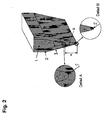
- FIG. 2 shows the basic structure of a cutting tool according to the present invention.
- a fine crystalline diamond layer 2 is arranged on a core 1.
- the core has two flanks tapering to a first, inner cutting edge, on the flanks of which the fine-crystalline diamond layer 2 is deposited.
- the diamond layer 2 in this case has a layer thickness y, which is measured orthogonally, for example, to an edge of the core 1. Also on the sides of the core that does not taper toward the first cutting edge, the diamond layer 2 may be applied, as in FIG FIG. 2 is shown.
- the diamond layer 2 follows the course of the two flanks of the core 1 and thus also tapers to a cutting edge, which closes off the diamond layer 2.
- the diamond layer 2 in this case has a layer thickness x, which corresponds to the smallest distance between the inner cutting edge of the core and the outer cutting edge, which is formed by the fine crystalline diamond layer 2.
- X is measured in the direction of the normal plane to the tangent of the outer cutting edge. Shown is also the cutting angle ⁇ , which is formed by the inclination of the outer edges of the cutting tool formed by the fine crystalline diamond layer.
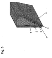
- FIG. 3 a further embodiment of the construction of the cutting tool according to the invention is shown.
- This cutting tool is formed asymmetrically with respect to the cutting edge 5.
- a core 1 is provided, on which a fine crystalline diamond layer 2 is deposited.
- an adhesion promoter layer 3 and a sliding layer 4 are further applied to the fine-grained diamond layer 2.
- a primer layer 3 come here, for example, vapor-deposited thin metal layers For example, from chromium, platinum, tungsten, titanium or silicon in question, while preferred sliding layers 4 polymer layers, for example of PTFE or carbon layers represent. The representation is not true to scale; usually the fine crystalline diamond layer is thicker than the primer layer.
- the core may consist, for example, of metallic materials or metal alloys, for example it is possible for the core material to be based on a steel material, a ceramic material or silicon.
- the following materials are suitable for the core: metals, such as titanium, nickel, chromium, niobium, tungsten, tantalum, molybdenum, vanadium, platinum, iron-containing materials, such as steel and / or germanium; carbon and / or nitrogen or boron-containing ceramics, such as silicon carbide, silicon nitride, boron nitride, tantalum carbide, tungsten carbide, molybdenum carbide, titanium nitrides, TiAlN, TiCN and / or TiB 2 , glass ceramics; Composites of ceramic materials in a metallic matrix (cermets); Hard metals; sintered carbide carbides such as cobalt or nickel bonded tungsten carbides or titanium carbides; Silicon, glass or sapphire; and single or polycrystalline
- the core material consists of monocrystalline or polycrystalline diamond;
- diamond-like carbon materials can be used for this purpose.
- the basic structure (with the exception of the metal layer 3 and the sliding layer 4) is therefore formed entirely of different diamond or diamond-like carbon materials.
- Fig. 3 also the cutting angle ⁇ is shown.
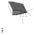
- FIG. 4 shows an embodiment of the present invention, which in principle has the same structure as in FIG. 3 shown, however, the cutting tool has a symmetrical design with respect to the cutting edge 5.
- Fig. 4 also the cutting angle ⁇ is shown.
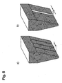
- FIG. 5 a further embodiment of the diamond blade according to the invention is shown, which has notches in the cutting edge.
- the core layer structure is not shown here for reasons of clarity.
- the notches are formed throughout by the diamond blade and can, for example, as in FIG. 5a shown to be formed at regular intervals.
- the regular spacing shown here may be, for example, less than 10 mm, for example 5 mm.
- FIG. 5b shows a further variant of the blade, wherein the notch is formed wider, the width of such a notch may for example be between 0.01 and 1 mm.
- FIG. 6 shows the basic process steps, which are passed through the inventive method for producing a cutting tool according to the invention.
- step a) a core material with an already predetermined cutting angle of the flanks is provided. Seed crystals of diamond are deposited on the flanks of the core material at least in certain areas (this step is not shown).
- step b) a finely crystalline diamond layer 2 is deposited by a method known from the prior art so that the cutting region, ie the region near the outer cutting edge, is completely covered with the fine-grained diamond layer 2.
- Step c) is a sharpening, ie a partial removal of the fine crystalline diamond layer; This step takes place by means of a plasma or ion etching process.
- FIG. 7 a further embodiment of a cutting tool according to the invention is shown, wherein the core is formed of polycrystalline materials, while on the fine crystalline diamond layer 2 is deposited. It can be seen that the average sizes of the crystallite domains of the core are much larger than the crystal domains of the fine crystalline diamond layer.
- hard metals, polycrystalline diamond, polycrystalline silicon, polycrystalline ceramic materials and / or polycrystalline metals can be used as core materials.
- FIG. 8 shows various embodiments of the cutting tool according to the invention, for example in the form of a machine knife a), a kitchen knife b) or differently designed blades c) or d). Also razor blades (see e)) are possible.
Landscapes
- Life Sciences & Earth Sciences (AREA)
- Forests & Forestry (AREA)
- Engineering & Computer Science (AREA)
- Mechanical Engineering (AREA)
- Cutting Tools, Boring Holders, And Turrets (AREA)
Claims (14)
- Outil de coupe comprenanta) un noyau, qui comprend deux flancs qui se rétrécissent en un tranchant interne, le tranchant interne présentant un premier rayon d'arrondi r1, etb) une couche de diamant finement cristalline appliquée au niveau du tranchant interne et au moins partiellement sur les flancs du noyau, avec une taille grains moyenne d50 ≤ 100 nm, qui forme un tranchant externe en suivant le contour des flancs du noyau qui se rétrécissent, la couche de diamant finement cristalline présentant, au niveau des flancs, une épaisseur de couche y entre 1 et 500 µm et présente, au niveau du tranchant externe, un deuxième rayon d'arrondi r2,
caractérisé en ce que
le deuxième rayon d'arrondi r2 est inférieur au premier rayon d'arrondi r1, avec pour condition que la couche de diamant finement cristalline présente, entre les tranchants interne et externe, une épaisseur de couche x, le rapport entre les épaisseurs de couches y/x (flanc/tranchant) de l'épaisseur de diamant finement cristallin est 0,1 ≤ y/x ≤ 0,6. - Outil de coupe selon la revendication 1, caractérisé en ce quea) le premier rayon d'arrondi r1 se situe entre 4 nm et 20 µm, de préférence entre 0,1 et 5 µm, de façon plus particulièrement préférée entre 0,5 et 3 µm, et/oub) le deuxième rayon d'arrondi r2 se situe entre 3 et 100 nm, de préférence entre 15 et 70 nm, de façon plus particulièrement préférée entre 20 et 50 nm.
- Outil de coupe selon l'une des revendications précédentes, caractérisé en ce que l'épaisseur de couche y de la couche de diamant finement cristalline se situe entre 1 et 50 µm, de façon plus particulièrement préférée entre 2 et 10 µm.
- Outil de coupe selon l'une des revendications précédentes, caractérisé en ce que la couche de diamant finement cristalline entre les tranchants interne et externe présente une épaisseur de couche x, le rapport entre les épaisseurs de couches y/x (flanc/tranchant) de la couche de diamant finement cristalline est 0,12 ≤ y/x ≤ 0,5, de préférence 0,13 ≤ y/x ≤ 0,25.
- Outil de coupe selon l'une des revendications précédentes, caractérisé en ce que l'angle de coupez se situe entre 10° et 40°, de préférence entre 10° et 30°, de façon plus particulièrement préférée entre 15° et 25°.
- Outil de coupe selon l'une des revendications précédentes, caractérisé en ce que le matériau du noyau est choisi dans le groupe constitué de métaux comme le titane, le nickel, le chrome, le niobium, le tungstène, le tantale, le molybdène, le vanadium, le platine, des matériaux ferreux comme l'acier et/ou le germanium ; de céramiques contenant du carbone et/ou de l'azote ou du bore, comme le carbure de silicium, le nitrure de silicium, le nitrure de bore, le carbure de tantale, le carbure de tungstène, le carbure de molybdène, le nitrure de titane, le TiAlN, le TiCN et/ou le TiB2, des céramiques vitreuses ; des matériaux composites constitués de matériaux céramiques dans une matrice métallique (cermets) ; des métaux durs ; des métaux durs du type carbures frittés, comme des carbures de tungstène ou des carbures de titane liés à du cobalt ou à du nickel ; du silicium, du verre ou du saphir ; ainsi qu'un diamant mono- ou polycristallin et/ou de couches de carbone à structure en diamant.
- Outil de coupe selon l'une des revendications précédentes, caractérisé en ce que le rapport r2/d50 entre le rayon d'arrondi de la couche de diamant au niveau l'arête externe du tranchant et la taille moyenne de grain du diamant finement cristallin se situe entre 0,03 et 20, de préférence entre 0,05 et 15, de façon plus particulièrement préférée entre 0,5 et 10.
- Outil de coupe selon l'une des revendications précédentes, caractérisé en ce que le gradient de taille moyenne de grain du diamant finement cristallin, mesuré dans la direction de l'épaisseur y de la couche de diamant finement cristalline, est < 300%, de préférence < 100%, de façon plus particulièrement préférée < 50%.
- Outil de coupe selon l'une des revendications précédentes, caractérisé en ce quea) entre le noyau et la couche de diamant finement cristalline, est appliquée au moins une première couche de promoteur d'adhérence, constituée de préférence de carbure de silicium, de nitrure de silicium, de tungstène, de titane ou de silicium, et/oub) sur la couche de diamant finement cristalline, est appliquée au moins une deuxième couche de promoteur d'adhérence, constituée de préférence de Cr, de Pt, de Ti ou de W, ainsi qu'une couche de glissement appliquée par-dessus, de préférence une couche de PTFE, une couche de carbone, de préférence une couche de graphite et/ou une couche de DLC.
- Outil de coupe selon l'une des revendications précédentes, caractérisé en ce que la couche de diamant présente une rugosité de surface moyenne RA < 5µm, de préférence < 2 µm, de façon plus particulièrement préférée < 1 µm.
- Outil de coupe selon l'une des revendications précédentes, caractérisé en ce que l'outil de coupe présente, à des intervalles réguliers, de préférence à des intervalles réguliers inférieurs à 10 mm, des entailles ou des sections.
- Outil de coupe selon l'une des revendications précédentes, caractérisé en ce que, dans le cas d'un matériau de noyau polycristallin, le diamètre de grain moyen d50 de la couche de diamant finement cristalline est inférieure au diamètre de grain moyen d50 du matériau de noyau polycristallin.
- Outil de coupe selon l'une des revendications précédentes, caractérisé en ce que les cristallites de la couche de diamant finement cristalline présentent une surtout une texture <100>, <110> ou <111>.
- Utilisation d'un outil de coupe selon l'une des revendications 1 à 13 en tant que lame, lame de couteau, lame de rasoir, système de rasage, scalpel, couteau, couteau de machine, ciseau ou comme ciseau de machine.
Priority Applications (1)
| Application Number | Priority Date | Filing Date | Title |
|---|---|---|---|
| EP20110001693 EP2495080B1 (fr) | 2011-03-01 | 2011-03-01 | Outil de coupe doté d'une lame en diamant cristallin fin |
Applications Claiming Priority (1)
| Application Number | Priority Date | Filing Date | Title |
|---|---|---|---|
| EP20110001693 EP2495080B1 (fr) | 2011-03-01 | 2011-03-01 | Outil de coupe doté d'une lame en diamant cristallin fin |
Publications (3)
| Publication Number | Publication Date |
|---|---|
| EP2495080A1 EP2495080A1 (fr) | 2012-09-05 |
| EP2495080A8 EP2495080A8 (fr) | 2012-10-24 |
| EP2495080B1 true EP2495080B1 (fr) | 2014-05-21 |
Family
ID=44310154
Family Applications (1)
| Application Number | Title | Priority Date | Filing Date |
|---|---|---|---|
| EP20110001693 Active EP2495080B1 (fr) | 2011-03-01 | 2011-03-01 | Outil de coupe doté d'une lame en diamant cristallin fin |
Country Status (1)
| Country | Link |
|---|---|
| EP (1) | EP2495080B1 (fr) |
Cited By (1)
| Publication number | Priority date | Publication date | Assignee | Title |
|---|---|---|---|---|
| US11230024B2 (en) | 2014-12-22 | 2022-01-25 | Bic-Violex Sa | Razor blade |
Families Citing this family (4)
| Publication number | Priority date | Publication date | Assignee | Title |
|---|---|---|---|---|
| EP2728300B1 (fr) * | 2012-10-31 | 2016-03-23 | Diamaze Coating Technology GmbH | Palpeur |
| ITBS20130073A1 (it) * | 2013-05-21 | 2014-11-22 | B E 4 S R L | Lama da taglio e suo metodo di realizzazione |
| WO2019084768A1 (fr) * | 2017-10-31 | 2019-05-09 | 深圳先进技术研究院 | Alliage dur présentant un revêtement de diamant et son procédé de préparation |
| EP4079473A1 (fr) * | 2021-04-20 | 2022-10-26 | GFD Gesellschaft für Diamantprodukte mbH | Élément de coupe et dispositif d'épilation |
Family Cites Families (9)
| Publication number | Priority date | Publication date | Assignee | Title |
|---|---|---|---|---|
| CH574312A5 (fr) * | 1974-04-10 | 1976-04-15 | Rotel Holding Ag | |
| DE3403196A1 (de) * | 1984-01-31 | 1985-08-01 | Reinhard Dr. 7101 Flein Dahlberg | Spitzen und schneiden mit extremer schaerfe |
| CN1064294C (zh) * | 1994-04-25 | 2001-04-11 | 吉莱特公司 | 制造剃刀刀片的方法 |
| US6353204B1 (en) | 1996-07-30 | 2002-03-05 | Paulus Gerhardus Hendrikus Maria Spaay | Method of producing a cutting tool insert using laser cutting and ion etching |
| DE19859905C2 (de) | 1998-01-27 | 2002-05-23 | Gfd Ges Fuer Diamantprodukte M | Diamantschneidwerkzeug |
| US20050028389A1 (en) * | 2001-06-12 | 2005-02-10 | Wort Christopher John Howard | Cvd diamond cutting insert |
| GB0212530D0 (en) | 2002-05-30 | 2002-07-10 | Diamanx Products Ltd | Diamond cutting insert |
| DE102004052068B4 (de) | 2004-10-26 | 2008-04-03 | GFD-Gesellschaft für Diamantprodukte mbH | Schneidwerkzeug und dessen Verwendung |
| US9327416B2 (en) * | 2009-07-17 | 2016-05-03 | The Gillette Company | Atomic layer deposition coatings on razor components |
-
2011
- 2011-03-01 EP EP20110001693 patent/EP2495080B1/fr active Active
Cited By (2)
| Publication number | Priority date | Publication date | Assignee | Title |
|---|---|---|---|---|
| US11230024B2 (en) | 2014-12-22 | 2022-01-25 | Bic-Violex Sa | Razor blade |
| US12397458B2 (en) | 2014-12-22 | 2025-08-26 | Bic-Violex Sa | Razor blade |
Also Published As
| Publication number | Publication date |
|---|---|
| EP2495080A1 (fr) | 2012-09-05 |
| EP2495080A8 (fr) | 2012-10-24 |
Similar Documents
| Publication | Publication Date | Title |
|---|---|---|
| EP2495081B1 (fr) | Outil de coupe doté d'une lame en diamant cristallin fin | |
| DE60002812T2 (de) | Verfahren zur Herstellung atomar scharfer Schneidklingen. | |
| DE69615219T2 (de) | Cdv beschichteter werkzeugeinsatz aus carbinitrid auf titanbasis | |
| EP2511229B1 (fr) | Composant micromécanique doté de flancs renforcés | |
| DE69333176T2 (de) | Verfahren zur Herstellung von einer synthetischer Diamantschicht | |
| DE60110386T2 (de) | Rasierklingentechnologie | |
| EP2495080B1 (fr) | Outil de coupe doté d'une lame en diamant cristallin fin | |
| EP3374139B1 (fr) | Lame de rasoir | |
| EP2978869B1 (fr) | Couches en matériau dur présentant une conductivité thermique définie | |
| DE112021002343T5 (de) | Rasiervorrichtung | |
| DE112021002346T5 (de) | Schneidmesser und Haarentfernungsvorrichtung | |
| EP3577253B1 (fr) | Outil revêtu | |
| DE102013218446A1 (de) | Werkzeug sowie Verfahren zum Zerspanen von faserverstärktenMaterialien | |
| DE69504896T2 (de) | Synthetische Diamantschicht mit verringerter Biegung und Verfahren zu ihrer Herstellung | |
| DE69010293T2 (de) | Mit Keramik überzogenes Sinterkarbidwerkzeug mit hoher Bruchbeständigkeit. | |
| DE112021002360T5 (de) | Schneidmesser und Haarentfernungsvorrichtung | |
| DE112021002350T5 (de) | Schneidmesser mit einer konkaven Abschrägung und Haarentfernungsvorrichtung | |
| EP2735540B1 (fr) | Composant micromécanique composite ayant un revêtement, son procédé de fabrication et son utilisation | |
| EP3221492B1 (fr) | Matériau de lame | |
| DE69503537T2 (de) | CVD Diamant Schneidwerkzeuge | |
| EP2625304B1 (fr) | Plaquette de coupe amovible et son procédé de production | |
| DE112021002355T5 (de) | Rasiervorrichtung | |
| EP1628923B1 (fr) | Roulette de coupe-verre | |
| EP3484643B1 (fr) | Procédé de fabrication d'un produit de métal dur et produit de métal dur | |
| DE102006004588A1 (de) | Haushaltsmesser |
Legal Events
| Date | Code | Title | Description |
|---|---|---|---|
| PUAI | Public reference made under article 153(3) epc to a published international application that has entered the european phase |
Free format text: ORIGINAL CODE: 0009012 |
|
| 17P | Request for examination filed |
Effective date: 20110902 |
|
| AK | Designated contracting states |
Kind code of ref document: A1 Designated state(s): AL AT BE BG CH CY CZ DE DK EE ES FI FR GB GR HR HU IE IS IT LI LT LU LV MC MK MT NL NO PL PT RO RS SE SI SK SM TR |
|
| AX | Request for extension of the european patent |
Extension state: BA ME |
|
| RIN1 | Information on inventor provided before grant (corrected) |
Inventor name: FLOETER, ANDRE, DR. Inventor name: STROBEL, STEFAN Inventor name: GLUCHE, PETER, DR.-ING. |
|
| 17Q | First examination report despatched |
Effective date: 20130719 |
|
| GRAP | Despatch of communication of intention to grant a patent |
Free format text: ORIGINAL CODE: EPIDOSNIGR1 |
|
| INTG | Intention to grant announced |
Effective date: 20140110 |
|
| GRAP | Despatch of communication of intention to grant a patent |
Free format text: ORIGINAL CODE: EPIDOSNIGR1 |
|
| INTG | Intention to grant announced |
Effective date: 20140227 |
|
| GRAS | Grant fee paid |
Free format text: ORIGINAL CODE: EPIDOSNIGR3 |
|
| GRAA | (expected) grant |
Free format text: ORIGINAL CODE: 0009210 |
|
| AK | Designated contracting states |
Kind code of ref document: B1 Designated state(s): AL AT BE BG CH CY CZ DE DK EE ES FI FR GB GR HR HU IE IS IT LI LT LU LV MC MK MT NL NO PL PT RO RS SE SI SK SM TR |
|
| REG | Reference to a national code |
Ref country code: GB Ref legal event code: FG4D Free format text: NOT ENGLISH |
|
| REG | Reference to a national code |
Ref country code: CH Ref legal event code: EP |
|
| REG | Reference to a national code |
Ref country code: AT Ref legal event code: REF Ref document number: 669373 Country of ref document: AT Kind code of ref document: T Effective date: 20140615 |
|
| REG | Reference to a national code |
Ref country code: IE Ref legal event code: FG4D Free format text: LANGUAGE OF EP DOCUMENT: GERMAN |
|
| REG | Reference to a national code |
Ref country code: DE Ref legal event code: R096 Ref document number: 502011003162 Country of ref document: DE Effective date: 20140703 |
|
| REG | Reference to a national code |
Ref country code: CH Ref legal event code: NV Representative=s name: TROESCH SCHEIDEGGER WERNER AG, CH |
|
| REG | Reference to a national code |
Ref country code: NL Ref legal event code: VDEP Effective date: 20140521 |
|
| REG | Reference to a national code |
Ref country code: LT Ref legal event code: MG4D |
|
| PG25 | Lapsed in a contracting state [announced via postgrant information from national office to epo] |
Ref country code: FI Free format text: LAPSE BECAUSE OF FAILURE TO SUBMIT A TRANSLATION OF THE DESCRIPTION OR TO PAY THE FEE WITHIN THE PRESCRIBED TIME-LIMIT Effective date: 20140521 Ref country code: GR Free format text: LAPSE BECAUSE OF FAILURE TO SUBMIT A TRANSLATION OF THE DESCRIPTION OR TO PAY THE FEE WITHIN THE PRESCRIBED TIME-LIMIT Effective date: 20140822 Ref country code: IS Free format text: LAPSE BECAUSE OF FAILURE TO SUBMIT A TRANSLATION OF THE DESCRIPTION OR TO PAY THE FEE WITHIN THE PRESCRIBED TIME-LIMIT Effective date: 20140921 Ref country code: NO Free format text: LAPSE BECAUSE OF FAILURE TO SUBMIT A TRANSLATION OF THE DESCRIPTION OR TO PAY THE FEE WITHIN THE PRESCRIBED TIME-LIMIT Effective date: 20140821 Ref country code: LT Free format text: LAPSE BECAUSE OF FAILURE TO SUBMIT A TRANSLATION OF THE DESCRIPTION OR TO PAY THE FEE WITHIN THE PRESCRIBED TIME-LIMIT Effective date: 20140521 |
|
| PG25 | Lapsed in a contracting state [announced via postgrant information from national office to epo] |
Ref country code: HR Free format text: LAPSE BECAUSE OF FAILURE TO SUBMIT A TRANSLATION OF THE DESCRIPTION OR TO PAY THE FEE WITHIN THE PRESCRIBED TIME-LIMIT Effective date: 20140521 Ref country code: ES Free format text: LAPSE BECAUSE OF FAILURE TO SUBMIT A TRANSLATION OF THE DESCRIPTION OR TO PAY THE FEE WITHIN THE PRESCRIBED TIME-LIMIT Effective date: 20140521 Ref country code: LV Free format text: LAPSE BECAUSE OF FAILURE TO SUBMIT A TRANSLATION OF THE DESCRIPTION OR TO PAY THE FEE WITHIN THE PRESCRIBED TIME-LIMIT Effective date: 20140521 Ref country code: PL Free format text: LAPSE BECAUSE OF FAILURE TO SUBMIT A TRANSLATION OF THE DESCRIPTION OR TO PAY THE FEE WITHIN THE PRESCRIBED TIME-LIMIT Effective date: 20140521 Ref country code: RS Free format text: LAPSE BECAUSE OF FAILURE TO SUBMIT A TRANSLATION OF THE DESCRIPTION OR TO PAY THE FEE WITHIN THE PRESCRIBED TIME-LIMIT Effective date: 20140521 Ref country code: SE Free format text: LAPSE BECAUSE OF FAILURE TO SUBMIT A TRANSLATION OF THE DESCRIPTION OR TO PAY THE FEE WITHIN THE PRESCRIBED TIME-LIMIT Effective date: 20140521 |
|
| PG25 | Lapsed in a contracting state [announced via postgrant information from national office to epo] |
Ref country code: PT Free format text: LAPSE BECAUSE OF FAILURE TO SUBMIT A TRANSLATION OF THE DESCRIPTION OR TO PAY THE FEE WITHIN THE PRESCRIBED TIME-LIMIT Effective date: 20140922 |
|
| PG25 | Lapsed in a contracting state [announced via postgrant information from national office to epo] |
Ref country code: SK Free format text: LAPSE BECAUSE OF FAILURE TO SUBMIT A TRANSLATION OF THE DESCRIPTION OR TO PAY THE FEE WITHIN THE PRESCRIBED TIME-LIMIT Effective date: 20140521 Ref country code: RO Free format text: LAPSE BECAUSE OF FAILURE TO SUBMIT A TRANSLATION OF THE DESCRIPTION OR TO PAY THE FEE WITHIN THE PRESCRIBED TIME-LIMIT Effective date: 20140521 Ref country code: EE Free format text: LAPSE BECAUSE OF FAILURE TO SUBMIT A TRANSLATION OF THE DESCRIPTION OR TO PAY THE FEE WITHIN THE PRESCRIBED TIME-LIMIT Effective date: 20140521 Ref country code: DK Free format text: LAPSE BECAUSE OF FAILURE TO SUBMIT A TRANSLATION OF THE DESCRIPTION OR TO PAY THE FEE WITHIN THE PRESCRIBED TIME-LIMIT Effective date: 20140521 Ref country code: CZ Free format text: LAPSE BECAUSE OF FAILURE TO SUBMIT A TRANSLATION OF THE DESCRIPTION OR TO PAY THE FEE WITHIN THE PRESCRIBED TIME-LIMIT Effective date: 20140521 |
|
| REG | Reference to a national code |
Ref country code: DE Ref legal event code: R097 Ref document number: 502011003162 Country of ref document: DE |
|
| PG25 | Lapsed in a contracting state [announced via postgrant information from national office to epo] |
Ref country code: NL Free format text: LAPSE BECAUSE OF FAILURE TO SUBMIT A TRANSLATION OF THE DESCRIPTION OR TO PAY THE FEE WITHIN THE PRESCRIBED TIME-LIMIT Effective date: 20140521 |
|
| PLBE | No opposition filed within time limit |
Free format text: ORIGINAL CODE: 0009261 |
|
| STAA | Information on the status of an ep patent application or granted ep patent |
Free format text: STATUS: NO OPPOSITION FILED WITHIN TIME LIMIT |
|
| 26N | No opposition filed |
Effective date: 20150224 |
|
| PG25 | Lapsed in a contracting state [announced via postgrant information from national office to epo] |
Ref country code: IT Free format text: LAPSE BECAUSE OF FAILURE TO SUBMIT A TRANSLATION OF THE DESCRIPTION OR TO PAY THE FEE WITHIN THE PRESCRIBED TIME-LIMIT Effective date: 20140521 |
|
| REG | Reference to a national code |
Ref country code: DE Ref legal event code: R097 Ref document number: 502011003162 Country of ref document: DE Effective date: 20150224 |
|
| PG25 | Lapsed in a contracting state [announced via postgrant information from national office to epo] |
Ref country code: SI Free format text: LAPSE BECAUSE OF FAILURE TO SUBMIT A TRANSLATION OF THE DESCRIPTION OR TO PAY THE FEE WITHIN THE PRESCRIBED TIME-LIMIT Effective date: 20140521 |
|
| PG25 | Lapsed in a contracting state [announced via postgrant information from national office to epo] |
Ref country code: MC Free format text: LAPSE BECAUSE OF FAILURE TO SUBMIT A TRANSLATION OF THE DESCRIPTION OR TO PAY THE FEE WITHIN THE PRESCRIBED TIME-LIMIT Effective date: 20140521 Ref country code: LU Free format text: LAPSE BECAUSE OF FAILURE TO SUBMIT A TRANSLATION OF THE DESCRIPTION OR TO PAY THE FEE WITHIN THE PRESCRIBED TIME-LIMIT Effective date: 20150301 |
|
| REG | Reference to a national code |
Ref country code: IE Ref legal event code: MM4A |
|
| PG25 | Lapsed in a contracting state [announced via postgrant information from national office to epo] |
Ref country code: IE Free format text: LAPSE BECAUSE OF NON-PAYMENT OF DUE FEES Effective date: 20150301 |
|
| REG | Reference to a national code |
Ref country code: FR Ref legal event code: PLFP Year of fee payment: 6 |
|
| PG25 | Lapsed in a contracting state [announced via postgrant information from national office to epo] |
Ref country code: MT Free format text: LAPSE BECAUSE OF FAILURE TO SUBMIT A TRANSLATION OF THE DESCRIPTION OR TO PAY THE FEE WITHIN THE PRESCRIBED TIME-LIMIT Effective date: 20140521 |
|
| REG | Reference to a national code |
Ref country code: FR Ref legal event code: PLFP Year of fee payment: 7 |
|
| REG | Reference to a national code |
Ref country code: AT Ref legal event code: MM01 Ref document number: 669373 Country of ref document: AT Kind code of ref document: T Effective date: 20160301 |
|
| PG25 | Lapsed in a contracting state [announced via postgrant information from national office to epo] |
Ref country code: SM Free format text: LAPSE BECAUSE OF FAILURE TO SUBMIT A TRANSLATION OF THE DESCRIPTION OR TO PAY THE FEE WITHIN THE PRESCRIBED TIME-LIMIT Effective date: 20140521 Ref country code: BG Free format text: LAPSE BECAUSE OF FAILURE TO SUBMIT A TRANSLATION OF THE DESCRIPTION OR TO PAY THE FEE WITHIN THE PRESCRIBED TIME-LIMIT Effective date: 20140521 Ref country code: HU Free format text: LAPSE BECAUSE OF FAILURE TO SUBMIT A TRANSLATION OF THE DESCRIPTION OR TO PAY THE FEE WITHIN THE PRESCRIBED TIME-LIMIT; INVALID AB INITIO Effective date: 20110301 |
|
| PG25 | Lapsed in a contracting state [announced via postgrant information from national office to epo] |
Ref country code: CY Free format text: LAPSE BECAUSE OF FAILURE TO SUBMIT A TRANSLATION OF THE DESCRIPTION OR TO PAY THE FEE WITHIN THE PRESCRIBED TIME-LIMIT Effective date: 20140521 |
|
| PG25 | Lapsed in a contracting state [announced via postgrant information from national office to epo] |
Ref country code: BE Free format text: LAPSE BECAUSE OF NON-PAYMENT OF DUE FEES Effective date: 20150331 |
|
| PG25 | Lapsed in a contracting state [announced via postgrant information from national office to epo] |
Ref country code: AT Free format text: LAPSE BECAUSE OF NON-PAYMENT OF DUE FEES Effective date: 20160301 Ref country code: TR Free format text: LAPSE BECAUSE OF FAILURE TO SUBMIT A TRANSLATION OF THE DESCRIPTION OR TO PAY THE FEE WITHIN THE PRESCRIBED TIME-LIMIT Effective date: 20140521 |
|
| REG | Reference to a national code |
Ref country code: FR Ref legal event code: PLFP Year of fee payment: 8 |
|
| PG25 | Lapsed in a contracting state [announced via postgrant information from national office to epo] |
Ref country code: MK Free format text: LAPSE BECAUSE OF FAILURE TO SUBMIT A TRANSLATION OF THE DESCRIPTION OR TO PAY THE FEE WITHIN THE PRESCRIBED TIME-LIMIT Effective date: 20140521 |
|
| PG25 | Lapsed in a contracting state [announced via postgrant information from national office to epo] |
Ref country code: AL Free format text: LAPSE BECAUSE OF FAILURE TO SUBMIT A TRANSLATION OF THE DESCRIPTION OR TO PAY THE FEE WITHIN THE PRESCRIBED TIME-LIMIT Effective date: 20140521 |
|
| P01 | Opt-out of the competence of the unified patent court (upc) registered |
Effective date: 20230525 |
|
| PGFP | Annual fee paid to national office [announced via postgrant information from national office to epo] |
Ref country code: CH Payment date: 20250401 Year of fee payment: 15 |
|
| REG | Reference to a national code |
Ref country code: CH Ref legal event code: U11 Free format text: ST27 STATUS EVENT CODE: U-0-0-U10-U11 (AS PROVIDED BY THE NATIONAL OFFICE) Effective date: 20260401 |
|
| PGFP | Annual fee paid to national office [announced via postgrant information from national office to epo] |
Ref country code: GB Payment date: 20260324 Year of fee payment: 16 |
|
| PGFP | Annual fee paid to national office [announced via postgrant information from national office to epo] |
Ref country code: DE Payment date: 20260318 Year of fee payment: 16 |
|
| PGFP | Annual fee paid to national office [announced via postgrant information from national office to epo] |
Ref country code: FR Payment date: 20260320 Year of fee payment: 16 |