EP2495192B1 - Dispositif et procédé d'amenée de récipients - Google Patents
Dispositif et procédé d'amenée de récipients Download PDFInfo
- Publication number
- EP2495192B1 EP2495192B1 EP11157031A EP11157031A EP2495192B1 EP 2495192 B1 EP2495192 B1 EP 2495192B1 EP 11157031 A EP11157031 A EP 11157031A EP 11157031 A EP11157031 A EP 11157031A EP 2495192 B1 EP2495192 B1 EP 2495192B1
- Authority
- EP
- European Patent Office
- Prior art keywords
- containers
- separating
- transport
- transport direction
- extended
- Prior art date
- Legal status (The legal status is an assumption and is not a legal conclusion. Google has not performed a legal analysis and makes no representation as to the accuracy of the status listed.)
- Active
Links
Images




Classifications
-
- B—PERFORMING OPERATIONS; TRANSPORTING
- B65—CONVEYING; PACKING; STORING; HANDLING THIN OR FILAMENTARY MATERIAL
- B65G—TRANSPORT OR STORAGE DEVICES, e.g. CONVEYORS FOR LOADING OR TIPPING, SHOP CONVEYOR SYSTEMS OR PNEUMATIC TUBE CONVEYORS
- B65G47/00—Article or material-handling devices associated with conveyors; Methods employing such devices
- B65G47/22—Devices influencing the relative position or the attitude of articles during transit by conveyors
- B65G47/26—Devices influencing the relative position or the attitude of articles during transit by conveyors arranging the articles, e.g. varying spacing between individual articles
- B65G47/28—Devices influencing the relative position or the attitude of articles during transit by conveyors arranging the articles, e.g. varying spacing between individual articles during transit by a single conveyor
- B65G47/29—Devices influencing the relative position or the attitude of articles during transit by conveyors arranging the articles, e.g. varying spacing between individual articles during transit by a single conveyor by temporarily stopping movement
Definitions
- the present invention relates to a method for introducing containers into a transport device.
- the descriptive a generic method FR 2 350 265 A1 discloses a device for treating containers (in particular bottles) which continuously pass on a conveyor belt.
- the bottles are first separated by a separating device and then fed to a control station.
- the bottles are held in place by forks and inspected by test units to be subsequently sorted out by the ejector units controlled by the test units in the event of defects identified.
- the present invention has for its object to provide a method for introducing containers, with which a robust transfer of containers of different sizes and at different speeds to a clocked transport device is ensured.
- the inventive method for feeding loosely lined upright containers in a transport device comprises the following steps: Separating the loosely lined containers successively in a transport direction by means of a rotatable separating device and sequential filling in the transport direction successively arranged storage positions of the separating device downstream stationary storage device with the isolated Containers, wherein the storage device comprises a plurality of in the transport direction arranged in series stoppers which are extended transversely to the transport direction, and a plurality of sensors which are arranged in the region of the storage positions or between the storage positions, wherein a predetermined sensor in each case a signal to one Control device transmitted and then a predetermined, preferably downstream, stopper is extended, whereby the S memory positions are filled sequentially.
- the separating wheel has a jacket surface coated with a soft plastic or rubber.
- the separating device may consist of two opposing separation brewers.
- the apparatus preferably has a conveyor belt for parking and advancing the containers, which extends from an area in front of the separating device to at least the storage device.
- a device suitable for the method according to the invention for introducing loosely lined upright containers into a transport device has a rotatable separating device which is designed to separate the loosely lined containers one after the other in a transport direction.
- the apparatus has a stationary storage device downstream of the separating device for the containers, which has a plurality of stoppers arranged in series in the transport direction, which are individually extendable transversely to the transport direction and thus a plurality of in Direction of transport define sequentially arranged storage positions for the containers.
- containers of different size and speed can be singulated and cached before being taken over by a clocked transport device.
- a mechanically particularly simple solution results if the separating device is designed as an intermittently driven separating wheel.
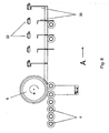
- FIG. 1 an embodiment of the device for introducing containers is shown in a transport device.
- the device comprises a conveyor belt 2, on which the containers 4 stand and are moved forward.
- the conveyor belt 2 typically moves at a constant speed in the transport direction (arrow A) of the containers 4.
- the containers 4 can be upright cans or vials and made of many different materials.
- the containers 4 are empty during the passage of the device or filled with desiccant containers or the like.
- the device also has a rotatable separating device, which in the illustrated embodiment is designed as an intermittently driven separating wheel 6.
- the rotational speed of the separating device during a rotation cycle is preferably lower than the speed of the conveyor belt 2, but may alternatively be higher.
- the rotatable separating device may, in addition to the illustrated embodiment, also consist of two opposing, individually driven separating wheels, a separating belt or two opposing separating belts.
- the separating wheel on a coated with soft plastic or rubber shell surface 8 which comes with the transported by the conveyor belt 2 in a loose juxtaposition upstanding containers 4 into contact and these due to the friction occurring between the lateral surface 8 and the containers 4 delayed in the transport direction A.
- the separating wheel 6 is in this case a linear guide rail 10 opposite, which ensures that the container 4 remain on the conveyor belt 2 and a back pressure is formed to the separating wheel 6.
- the device Downstream of the separating device 6, the device comprises a stationary spindle device 12 for the containers 4.
- the conveyor belt 2 extends from an area in front of the separating device 6 to at least the storage device 12.
- the guide rail 10 likewise preferably extends from the separating device 6 to the end of the separating device 6 Memory device 12.
- the storage device 12 serves to temporarily store the containers 4 separated by the separating device 6 at defined intervals in order to subsequently transfer them to a clocked transport device 14.
- the transport device 14 is designed here as a sliding rake, which is reciprocable both in the transport direction A of the container 4 and transversely to the transport direction of the container and herverschiebbar.
- the containers 4 are received in receptacles 16 of the sliding rake, which open to the storage device 12 out and are designed in the illustrated preferred embodiment substantially triangular. This results in the possibility of a variable adaptation to different container sizes.
- the counter-holding surface 18 is preferably smooth to generate the lowest possible friction with the containers 4 and serves to support the container 4 moved forward by the transport device 14.
- the counter-holding surface 18 extends over the entire length of the slide rake in the illustrated example.
- the stationary storage device 12 for the containers 4 has a plurality of stoppers 20 arranged in series in the transport direction, which can be controlled individually. Each stopper 20 can thus be extended transversely to the transport direction, whereby a plurality of successively arranged in the transport direction storage positions is defined. Each storage position is in this case assigned a container 4, however, two storage positions can be occupied by a single large container 4, as will be explained in more detail later.
- the stoppers 20 are movable, for example via suitable pneumatics. Other types of drive are conceivable for the expert.
- the memory device 12 also has a plurality of sensors 22 which are arranged in the region of the memory positions or between the memory positions. If a particular sensor 22 detects a passing container 4 (e.g., its rising or falling edge), that sensor 22 will provide appropriate signals to a controller (not shown) which will cause a predetermined stop 20 to be extended in response. As a rule, the control device is programmed in such a way because of the time delay that always the next downstream or next stopper 20 is extended.
- each individual container 4 enters the storage device 12, in which the individual storage positions are filled up sequentially with containers 4.
- the memory device 12 has five stoppers 20, of which only the third stopper 20 is extended at the beginning of the filling process of the memory device 12.
- the next stopper 20 in the present case the second stopper 20 viewed from the left, moves up to the third stopper, whereupon the associated storage position fills with the next container 4 again, etc.
- Fig. 3 the filling of the storage device 12 is shown with three containers 4 at the three left-most storage positions. Subsequently, the three stored containers 4, as in Fig. 4 is shown, further moved, wherein the three previously extended stopper 20 must be retracted simultaneously to allow further movement of the container 4. The further movement of the container 4 is preferably carried out by means of the clocked transport device 14, the only in Fig. 1 and 12 is shown.
- Fig. 4 is the result of the clocked shift step shown.
- the containers 4 have been moved by three positions, and the filling process of the three left-hand storage positions of the storage device 12 can start again from the beginning. In this way, a clocked transfer of arranged at a defined distance containers 4 to other processing stations is possible.
- Fig. 5 to Fig. 8 a similar filling of the memory device 12 is described, wherein only two containers 4 are simultaneously introduced into the memory device 12 before they are moved on by the clocked transport device 14.
- Fig. 9 to 12 an introduction of containers 4 of larger diameter is shown schematically. In this case, every second stopper 20 is not extended.
- the sensors 22 and stoppers 20 may also be coupled by the control device in other suitable ways.
- the memory device 12 can be moved to adapt the format as a whole transversely to the transport direction A of the container 4.
Landscapes
- Engineering & Computer Science (AREA)
- Mechanical Engineering (AREA)
- Special Conveying (AREA)
- Attitude Control For Articles On Conveyors (AREA)
Claims (7)
- Procédé destiné à sasser des récipients (4), se tenant debout et juxtaposés de façon lâche, dans un dispositif de transport (14), comprenant les étapes suivantes :séparation successive des récipients (4), juxtaposés de façon lâche, dans un dispositif de transport (A) au moyen d'un dispositif de séparation (6) rotatif,chargement de positions de stockage, disposées les unes derrière les autres dans la direction de transport, d'un dispositif de stockage (12) stationnaire, monté en aval du dispositif de séparation (6), par les récipients (4) séparés, le dispositif de stockage (12) comprenant une pluralité d'arrêtoirs (20), qui sont disposés en rangée dans la direction de transport et sortis transversalement à la direction de transport, et une pluralité de capteurs (22), qui sont disposés dans la zone des positions de stockage ou entre les positions de stockage,caractérisé en ce que
un capteur prédéfini (22) transmet respectivement un signal à un dispositif de commande et un arrêtoir (20) prédéfini est sorti en réaction, de sorte que les arrêtoirs (20) sont sortis individuellement et les positions de stockage sont chargées de façon séquentielle. - Procédé selon la revendication 1, caractérisé en ce que l'arrêtoir (20) prédéfini est placé en aval du capteur (22) respectif prédéfini.
- Procédé selon l'une des revendications 1 et 2, caractérisé en ce que tous les arrêtoirs (20) sortis sont rentrés simultanément pour un transfert des récipients (4) sur le dispositif de transport (14).
- Procédé selon l'une des revendications précédentes, caractérisé en ce que le dispositif de séparation (6) est constitué de deux bandes de séparation en vis-à-vis.
- Procédé selon l'une des revendications 1 à 3, caractérisé en ce que le dispositif de séparation (6) est réalisé sous forme de roue de séparation entraînée par intermittence.
- Procédé selon la revendication 5, caractérisé en ce que la roue de séparation (6) présente une surface d'enveloppe (8) revêtue de matière plastique souple ou de caoutchouc.
- Procédé selon l'une des revendications précédentes, caractérisé en ce qu'il est prévu une bande transporteuse (2) pour l'arrêt et le mouvement d'avance des récipients (4), laquelle bande s'étend d'une zone en amont du dispositif de séparation (6) jusqu'au moins le dispositif de stockage (12).
Priority Applications (2)
| Application Number | Priority Date | Filing Date | Title |
|---|---|---|---|
| EP11157031A EP2495192B1 (fr) | 2011-03-04 | 2011-03-04 | Dispositif et procédé d'amenée de récipients |
| US13/369,753 US8499923B2 (en) | 2011-03-04 | 2012-02-09 | Device and method for channeling containers |
Applications Claiming Priority (1)
| Application Number | Priority Date | Filing Date | Title |
|---|---|---|---|
| EP11157031A EP2495192B1 (fr) | 2011-03-04 | 2011-03-04 | Dispositif et procédé d'amenée de récipients |
Publications (2)
| Publication Number | Publication Date |
|---|---|
| EP2495192A1 EP2495192A1 (fr) | 2012-09-05 |
| EP2495192B1 true EP2495192B1 (fr) | 2012-12-26 |
Family
ID=44315024
Family Applications (1)
| Application Number | Title | Priority Date | Filing Date |
|---|---|---|---|
| EP11157031A Active EP2495192B1 (fr) | 2011-03-04 | 2011-03-04 | Dispositif et procédé d'amenée de récipients |
Country Status (2)
| Country | Link |
|---|---|
| US (1) | US8499923B2 (fr) |
| EP (1) | EP2495192B1 (fr) |
Families Citing this family (1)
| Publication number | Priority date | Publication date | Assignee | Title |
|---|---|---|---|---|
| EP2495193B1 (fr) * | 2011-03-04 | 2013-02-27 | UHLMANN PAC-SYSTEME GmbH & Co. KG | Dispositif d'évacuation de récipients |
Family Cites Families (21)
| Publication number | Priority date | Publication date | Assignee | Title |
|---|---|---|---|---|
| US2771177A (en) * | 1953-07-30 | 1956-11-20 | Owens Illinois Glass Co | Article grouping apparatus |
| US2744608A (en) * | 1954-07-26 | 1956-05-08 | Emhart Mfg Co | Star wheel transfer mechanism for cans or the like |
| US3987889A (en) * | 1972-12-18 | 1976-10-26 | Aurora Nieto Godoy | Distributor mechanism for articles coming off a conveyor |
| FR2350285A1 (fr) * | 1976-05-04 | 1977-12-02 | Tourres Francois | Installations de manutention en continu de conteneurs, tels que notamment des bouteilles de verre |
| FR2487308A1 (fr) * | 1980-07-23 | 1982-01-29 | Remy Ets Pierre | Dispositif pour amener des bouteilles a un poste de traitement et les immobiliser dans ce poste |
| US5070992A (en) * | 1989-01-24 | 1991-12-10 | Forma-Pack, L.P. | Conveyor system |
| US5161664A (en) * | 1990-03-13 | 1992-11-10 | The Mead Corporation | Infeed grouping mechanism for a packaging machine |
| IT1294101B1 (it) * | 1997-07-18 | 1999-03-22 | Sasib Beverage S P A Ora Sasib | Procedimento e dispositivo di arresto ammortizzato ed accompagnamento di contenitori, in linea di trasporto per contenitori. |
| US5979147A (en) * | 1997-12-30 | 1999-11-09 | Riverwood International Corporation | Article grouping assembly and method for a packaging machine |
| US6460683B1 (en) * | 1999-11-22 | 2002-10-08 | Seagate Technology Llc | Conveyor with flexible zone parameter control |
| EP1116675B1 (fr) * | 1999-12-29 | 2006-10-04 | Aries Packaging | Dispositif pour la constitution de lots successifs d'articles comprenant des moyens de transfert des articles |
| DK1299298T3 (da) * | 2000-07-07 | 2004-07-26 | Ferag Ag | Fremgangsmåde og indretning til holdt transport af genstande på en transportstrækning med bufferlager |
| US6895730B2 (en) * | 2000-11-03 | 2005-05-24 | Standard Knapp Inc. | Packaging machine |
| DE10154203B4 (de) * | 2000-11-30 | 2004-05-27 | Ulrich Kremser | Einlaufsystem für flaschenverarbeitende Maschinen in der Getränke- und Abfülltechnik |
| US6889485B2 (en) * | 2002-02-09 | 2005-05-10 | Meadwestvaco Packaging Systems, Llc | Article grouping mechanism |
| ITBO20030470A1 (it) * | 2003-08-01 | 2005-02-02 | Gd Spa | Macchina automatica per il trattamento di articoli e provvista di un dispositivo di rilevamento di posizione con sensori ad effetto di hall. |
| FR2859714B1 (fr) * | 2003-09-12 | 2005-11-11 | Aries Packaging | Procede de formation et d'espacement de lots successifs d'articles |
| JP4567740B2 (ja) * | 2004-09-02 | 2010-10-20 | グラフィック パッケージング インターナショナル インコーポレイテッド | 詰め込みカルーセルを有する梱包システム |
| JP5246161B2 (ja) * | 2007-07-02 | 2013-07-24 | 東芝三菱電機産業システム株式会社 | トラッキング装置 |
| EP2273508B1 (fr) * | 2009-07-07 | 2013-12-11 | AREVA GmbH | Installation d'isolation et procédé d'isolation associé |
| DE102009026395A1 (de) * | 2009-08-18 | 2011-02-24 | Krones Ag | Vorrichtung zum Gruppieren und/oder Vereinzeln von Artikeln |
-
2011
- 2011-03-04 EP EP11157031A patent/EP2495192B1/fr active Active
-
2012
- 2012-02-09 US US13/369,753 patent/US8499923B2/en active Active
Also Published As
| Publication number | Publication date |
|---|---|
| US8499923B2 (en) | 2013-08-06 |
| EP2495192A1 (fr) | 2012-09-05 |
| US20120222936A1 (en) | 2012-09-06 |
Similar Documents
| Publication | Publication Date | Title |
|---|---|---|
| EP2836447B1 (fr) | Dispositif et procédé de transport de produits en morceaux | |
| DE102004023473B4 (de) | Verpackungsmaschine und Verfahren zum Zuführen von Behältern in einer Verpackungsmaschine | |
| EP3153025B1 (fr) | Dispositif destine au traitement individuel de saucisse | |
| EP3853156B1 (fr) | Procédé et dispositif d'acheminement de produits d'un premier processus vers un second processus dans une installation d'emballage | |
| EP3539910B1 (fr) | Système de bande transporteuse pour mettre en place des produits dans un agencement prédéfini | |
| EP2298651B1 (fr) | Procédé et dispositif destinés au groupement d'articles | |
| DE102012004372A1 (de) | Schalenverschließmaschine und Verfahren zum Transportieren von Schalen | |
| DE102013111088A1 (de) | Verfahren und System zum Abführen von auf einer Horizontalfördereinrichtung kontinuierlich bewegten und in parallelen Reihen geführten Getränkebehältnissen | |
| DE102007021146A1 (de) | Vorrichtung und Verfahren zum Handhaben von flachen Gegenständen, insbesondere Windeln | |
| CH702396B1 (de) | Verfahren und Vorrichtung zum fortlaufenden Vereinzeln und Ausrichten von einseitig geschlossenen zylindrischen Hohlkörpern, insbesondere von Schraubverschlüssen für Flaschen. | |
| EP2799348A1 (fr) | Procédé de regroupement d'articles en un faisceau d'articles et dispositif de regroupement et machine d'emballage doté d'un tel dispositif | |
| EP2495193B1 (fr) | Dispositif d'évacuation de récipients | |
| EP2818421A1 (fr) | Machine de fermeture de barquettes avec une alimentation de barquettes et procédé pour une installation d'emballage | |
| EP3160878B1 (fr) | Procédé et dispositif de transport de produits fragmentés | |
| WO2020069803A1 (fr) | Dispositif et procédé de transport d'une pluralité d'articles | |
| CH710103A2 (de) | Verfahren und Vorrichtung zum Handhaben von langgestreckten Gegenständen. | |
| EP2495192B1 (fr) | Dispositif et procédé d'amenée de récipients | |
| EP2384652A2 (fr) | Dispositif de remplissage de combles avec des articles en forme de tiges et machine de fabrication pour articles en forme de tiges dotée d'un tel dispositif | |
| DE102013219847A1 (de) | Vorrichtung und Verfahren zum Umgang mit Artikeln | |
| EP4029811A1 (fr) | Bande transporteuse destinée au transport des marchandises à transporter et ligne d'emballage d'une installation d'emballage doté d'une telle bande transporteuse | |
| DE202012007853U1 (de) | Vorrichtung zum Ausleiten von Gegenständen | |
| WO2017144157A2 (fr) | Dispositif d'usinage, installation et procédé d'usinage pour des contenants de différents types | |
| EP3613293B1 (fr) | Dispositif et procédé de traitement de saucisses | |
| WO2016142231A1 (fr) | Procédé et dispositif pour éviter des emballages vides | |
| WO2006111142A1 (fr) | Machine d'emballage |
Legal Events
| Date | Code | Title | Description |
|---|---|---|---|
| PUAI | Public reference made under article 153(3) epc to a published international application that has entered the european phase |
Free format text: ORIGINAL CODE: 0009012 |
|
| 17P | Request for examination filed |
Effective date: 20111010 |
|
| AK | Designated contracting states |
Kind code of ref document: A1 Designated state(s): AL AT BE BG CH CY CZ DE DK EE ES FI FR GB GR HR HU IE IS IT LI LT LU LV MC MK MT NL NO PL PT RO RS SE SI SK SM TR |
|
| AX | Request for extension of the european patent |
Extension state: BA ME |
|
| GRAP | Despatch of communication of intention to grant a patent |
Free format text: ORIGINAL CODE: EPIDOSNIGR1 |
|
| GRAS | Grant fee paid |
Free format text: ORIGINAL CODE: EPIDOSNIGR3 |
|
| GRAA | (expected) grant |
Free format text: ORIGINAL CODE: 0009210 |
|
| AK | Designated contracting states |
Kind code of ref document: B1 Designated state(s): AL AT BE BG CH CY CZ DE DK EE ES FI FR GB GR HR HU IE IS IT LI LT LU LV MC MK MT NL NO PL PT RO RS SE SI SK SM TR |
|
| REG | Reference to a national code |
Ref country code: GB Ref legal event code: FG4D Free format text: NOT ENGLISH |
|
| REG | Reference to a national code |
Ref country code: CH Ref legal event code: EP |
|
| REG | Reference to a national code |
Ref country code: AT Ref legal event code: REF Ref document number: 590317 Country of ref document: AT Kind code of ref document: T Effective date: 20130115 |
|
| REG | Reference to a national code |
Ref country code: DE Ref legal event code: R096 Ref document number: 502011000309 Country of ref document: DE Effective date: 20130307 |
|
| PG25 | Lapsed in a contracting state [announced via postgrant information from national office to epo] |
Ref country code: LT Free format text: LAPSE BECAUSE OF FAILURE TO SUBMIT A TRANSLATION OF THE DESCRIPTION OR TO PAY THE FEE WITHIN THE PRESCRIBED TIME-LIMIT Effective date: 20121226 Ref country code: HR Free format text: LAPSE BECAUSE OF FAILURE TO SUBMIT A TRANSLATION OF THE DESCRIPTION OR TO PAY THE FEE WITHIN THE PRESCRIBED TIME-LIMIT Effective date: 20121226 Ref country code: NO Free format text: LAPSE BECAUSE OF FAILURE TO SUBMIT A TRANSLATION OF THE DESCRIPTION OR TO PAY THE FEE WITHIN THE PRESCRIBED TIME-LIMIT Effective date: 20130326 Ref country code: FI Free format text: LAPSE BECAUSE OF FAILURE TO SUBMIT A TRANSLATION OF THE DESCRIPTION OR TO PAY THE FEE WITHIN THE PRESCRIBED TIME-LIMIT Effective date: 20121226 Ref country code: SE Free format text: LAPSE BECAUSE OF FAILURE TO SUBMIT A TRANSLATION OF THE DESCRIPTION OR TO PAY THE FEE WITHIN THE PRESCRIBED TIME-LIMIT Effective date: 20121226 |
|
| REG | Reference to a national code |
Ref country code: NL Ref legal event code: T3 |
|
| REG | Reference to a national code |
Ref country code: LT Ref legal event code: MG4D |
|
| PG25 | Lapsed in a contracting state [announced via postgrant information from national office to epo] |
Ref country code: GR Free format text: LAPSE BECAUSE OF FAILURE TO SUBMIT A TRANSLATION OF THE DESCRIPTION OR TO PAY THE FEE WITHIN THE PRESCRIBED TIME-LIMIT Effective date: 20130327 Ref country code: SI Free format text: LAPSE BECAUSE OF FAILURE TO SUBMIT A TRANSLATION OF THE DESCRIPTION OR TO PAY THE FEE WITHIN THE PRESCRIBED TIME-LIMIT Effective date: 20121226 Ref country code: LV Free format text: LAPSE BECAUSE OF FAILURE TO SUBMIT A TRANSLATION OF THE DESCRIPTION OR TO PAY THE FEE WITHIN THE PRESCRIBED TIME-LIMIT Effective date: 20121226 |
|
| PG25 | Lapsed in a contracting state [announced via postgrant information from national office to epo] |
Ref country code: RS Free format text: LAPSE BECAUSE OF FAILURE TO SUBMIT A TRANSLATION OF THE DESCRIPTION OR TO PAY THE FEE WITHIN THE PRESCRIBED TIME-LIMIT Effective date: 20121226 Ref country code: EE Free format text: LAPSE BECAUSE OF FAILURE TO SUBMIT A TRANSLATION OF THE DESCRIPTION OR TO PAY THE FEE WITHIN THE PRESCRIBED TIME-LIMIT Effective date: 20121226 Ref country code: CZ Free format text: LAPSE BECAUSE OF FAILURE TO SUBMIT A TRANSLATION OF THE DESCRIPTION OR TO PAY THE FEE WITHIN THE PRESCRIBED TIME-LIMIT Effective date: 20121226 Ref country code: BG Free format text: LAPSE BECAUSE OF FAILURE TO SUBMIT A TRANSLATION OF THE DESCRIPTION OR TO PAY THE FEE WITHIN THE PRESCRIBED TIME-LIMIT Effective date: 20130326 Ref country code: ES Free format text: LAPSE BECAUSE OF FAILURE TO SUBMIT A TRANSLATION OF THE DESCRIPTION OR TO PAY THE FEE WITHIN THE PRESCRIBED TIME-LIMIT Effective date: 20130406 Ref country code: SK Free format text: LAPSE BECAUSE OF FAILURE TO SUBMIT A TRANSLATION OF THE DESCRIPTION OR TO PAY THE FEE WITHIN THE PRESCRIBED TIME-LIMIT Effective date: 20121226 Ref country code: IS Free format text: LAPSE BECAUSE OF FAILURE TO SUBMIT A TRANSLATION OF THE DESCRIPTION OR TO PAY THE FEE WITHIN THE PRESCRIBED TIME-LIMIT Effective date: 20130426 |
|
| PG25 | Lapsed in a contracting state [announced via postgrant information from national office to epo] |
Ref country code: PL Free format text: LAPSE BECAUSE OF FAILURE TO SUBMIT A TRANSLATION OF THE DESCRIPTION OR TO PAY THE FEE WITHIN THE PRESCRIBED TIME-LIMIT Effective date: 20121226 Ref country code: PT Free format text: LAPSE BECAUSE OF FAILURE TO SUBMIT A TRANSLATION OF THE DESCRIPTION OR TO PAY THE FEE WITHIN THE PRESCRIBED TIME-LIMIT Effective date: 20130426 Ref country code: RO Free format text: LAPSE BECAUSE OF FAILURE TO SUBMIT A TRANSLATION OF THE DESCRIPTION OR TO PAY THE FEE WITHIN THE PRESCRIBED TIME-LIMIT Effective date: 20121226 |
|
| BERE | Be: lapsed |
Owner name: UHLMANN PAC-SYSTEME G.M.B.H. & CO. KG Effective date: 20130331 |
|
| PG25 | Lapsed in a contracting state [announced via postgrant information from national office to epo] |
Ref country code: DK Free format text: LAPSE BECAUSE OF FAILURE TO SUBMIT A TRANSLATION OF THE DESCRIPTION OR TO PAY THE FEE WITHIN THE PRESCRIBED TIME-LIMIT Effective date: 20121226 Ref country code: MC Free format text: LAPSE BECAUSE OF NON-PAYMENT OF DUE FEES Effective date: 20130331 |
|
| PLBE | No opposition filed within time limit |
Free format text: ORIGINAL CODE: 0009261 |
|
| STAA | Information on the status of an ep patent application or granted ep patent |
Free format text: STATUS: NO OPPOSITION FILED WITHIN TIME LIMIT |
|
| PG25 | Lapsed in a contracting state [announced via postgrant information from national office to epo] |
Ref country code: CY Free format text: LAPSE BECAUSE OF FAILURE TO SUBMIT A TRANSLATION OF THE DESCRIPTION OR TO PAY THE FEE WITHIN THE PRESCRIBED TIME-LIMIT Effective date: 20121226 |
|
| 26N | No opposition filed |
Effective date: 20130927 |
|
| REG | Reference to a national code |
Ref country code: FR Ref legal event code: ST Effective date: 20131129 |
|
| REG | Reference to a national code |
Ref country code: IE Ref legal event code: MM4A |
|
| REG | Reference to a national code |
Ref country code: DE Ref legal event code: R097 Ref document number: 502011000309 Country of ref document: DE Effective date: 20130927 |
|
| PG25 | Lapsed in a contracting state [announced via postgrant information from national office to epo] |
Ref country code: IE Free format text: LAPSE BECAUSE OF NON-PAYMENT OF DUE FEES Effective date: 20130304 Ref country code: FR Free format text: LAPSE BECAUSE OF NON-PAYMENT OF DUE FEES Effective date: 20130402 Ref country code: BE Free format text: LAPSE BECAUSE OF NON-PAYMENT OF DUE FEES Effective date: 20130331 Ref country code: AL Free format text: LAPSE BECAUSE OF FAILURE TO SUBMIT A TRANSLATION OF THE DESCRIPTION OR TO PAY THE FEE WITHIN THE PRESCRIBED TIME-LIMIT Effective date: 20121226 |
|
| PG25 | Lapsed in a contracting state [announced via postgrant information from national office to epo] |
Ref country code: MT Free format text: LAPSE BECAUSE OF FAILURE TO SUBMIT A TRANSLATION OF THE DESCRIPTION OR TO PAY THE FEE WITHIN THE PRESCRIBED TIME-LIMIT Effective date: 20121226 |
|
| REG | Reference to a national code |
Ref country code: CH Ref legal event code: PL |
|
| PG25 | Lapsed in a contracting state [announced via postgrant information from national office to epo] |
Ref country code: LI Free format text: LAPSE BECAUSE OF NON-PAYMENT OF DUE FEES Effective date: 20140331 Ref country code: CH Free format text: LAPSE BECAUSE OF NON-PAYMENT OF DUE FEES Effective date: 20140331 |
|
| PG25 | Lapsed in a contracting state [announced via postgrant information from national office to epo] |
Ref country code: SM Free format text: LAPSE BECAUSE OF FAILURE TO SUBMIT A TRANSLATION OF THE DESCRIPTION OR TO PAY THE FEE WITHIN THE PRESCRIBED TIME-LIMIT Effective date: 20121226 |
|
| PG25 | Lapsed in a contracting state [announced via postgrant information from national office to epo] |
Ref country code: TR Free format text: LAPSE BECAUSE OF FAILURE TO SUBMIT A TRANSLATION OF THE DESCRIPTION OR TO PAY THE FEE WITHIN THE PRESCRIBED TIME-LIMIT Effective date: 20121226 |
|
| PG25 | Lapsed in a contracting state [announced via postgrant information from national office to epo] |
Ref country code: MK Free format text: LAPSE BECAUSE OF FAILURE TO SUBMIT A TRANSLATION OF THE DESCRIPTION OR TO PAY THE FEE WITHIN THE PRESCRIBED TIME-LIMIT Effective date: 20121226 Ref country code: HU Free format text: LAPSE BECAUSE OF FAILURE TO SUBMIT A TRANSLATION OF THE DESCRIPTION OR TO PAY THE FEE WITHIN THE PRESCRIBED TIME-LIMIT; INVALID AB INITIO Effective date: 20110304 Ref country code: LU Free format text: LAPSE BECAUSE OF NON-PAYMENT OF DUE FEES Effective date: 20130304 |
|
| REG | Reference to a national code |
Ref country code: AT Ref legal event code: MM01 Ref document number: 590317 Country of ref document: AT Kind code of ref document: T Effective date: 20160304 |
|
| PG25 | Lapsed in a contracting state [announced via postgrant information from national office to epo] |
Ref country code: AT Free format text: LAPSE BECAUSE OF NON-PAYMENT OF DUE FEES Effective date: 20160304 |
|
| REG | Reference to a national code |
Ref country code: DE Ref legal event code: R082 Ref document number: 502011000309 Country of ref document: DE Representative=s name: KROHER . STROBEL RECHTS- UND PATENTANWAELTE PA, DE Ref country code: DE Ref legal event code: R081 Ref document number: 502011000309 Country of ref document: DE Owner name: UHLMANN PAC-SYSTEME GMBH & CO. KG, DE Free format text: FORMER OWNER: UHLMANN PAC-SYSTEME GMBH & CO KG, 88471 LAUPHEIM, DE Ref country code: DE Ref legal event code: R082 Ref document number: 502011000309 Country of ref document: DE Representative=s name: KROHER STROBEL RECHTS- UND PATENTANWAELTE PART, DE |
|
| REG | Reference to a national code |
Ref country code: DE Ref legal event code: R082 Ref document number: 502011000309 Country of ref document: DE Representative=s name: KROHER STROBEL RECHTS- UND PATENTANWAELTE PART, DE |
|
| PGFP | Annual fee paid to national office [announced via postgrant information from national office to epo] |
Ref country code: IT Payment date: 20250327 Year of fee payment: 15 |
|
| PGFP | Annual fee paid to national office [announced via postgrant information from national office to epo] |
Ref country code: GB Payment date: 20260317 Year of fee payment: 16 |
|
| PGFP | Annual fee paid to national office [announced via postgrant information from national office to epo] |
Ref country code: DE Payment date: 20260327 Year of fee payment: 16 |
|
| PGFP | Annual fee paid to national office [announced via postgrant information from national office to epo] |
Ref country code: NL Payment date: 20260330 Year of fee payment: 16 |