EP2495400A2 - Ensemble de carter de turbomachine - Google Patents
Ensemble de carter de turbomachine Download PDFInfo
- Publication number
- EP2495400A2 EP2495400A2 EP12152501A EP12152501A EP2495400A2 EP 2495400 A2 EP2495400 A2 EP 2495400A2 EP 12152501 A EP12152501 A EP 12152501A EP 12152501 A EP12152501 A EP 12152501A EP 2495400 A2 EP2495400 A2 EP 2495400A2
- Authority
- EP
- European Patent Office
- Prior art keywords
- casing
- liner
- turbomachine
- assembly
- casing element
- Prior art date
- Legal status (The legal status is an assumption and is not a legal conclusion. Google has not performed a legal analysis and makes no representation as to the accuracy of the status listed.)
- Withdrawn
Links
- 239000011800 void material Substances 0.000 claims abstract description 20
- 239000004411 aluminium Substances 0.000 description 7
- 229910052782 aluminium Inorganic materials 0.000 description 7
- XAGFODPZIPBFFR-UHFFFAOYSA-N aluminium Chemical compound [Al] XAGFODPZIPBFFR-UHFFFAOYSA-N 0.000 description 7
- 239000000463 material Substances 0.000 description 5
- 239000000945 filler Substances 0.000 description 3
- 239000002184 metal Substances 0.000 description 3
- 229910052751 metal Inorganic materials 0.000 description 3
- OKTJSMMVPCPJKN-UHFFFAOYSA-N Carbon Chemical compound [C] OKTJSMMVPCPJKN-UHFFFAOYSA-N 0.000 description 2
- 229920002430 Fibre-reinforced plastic Polymers 0.000 description 2
- 239000004760 aramid Substances 0.000 description 2
- 229920003235 aromatic polyamide Polymers 0.000 description 2
- 230000008901 benefit Effects 0.000 description 2
- 229910052799 carbon Inorganic materials 0.000 description 2
- 230000006378 damage Effects 0.000 description 2
- 230000000694 effects Effects 0.000 description 2
- 239000000835 fiber Substances 0.000 description 2
- 239000006260 foam Substances 0.000 description 2
- 239000003365 glass fiber Substances 0.000 description 2
- 238000009434 installation Methods 0.000 description 2
- 238000004519 manufacturing process Methods 0.000 description 2
- 239000007787 solid Substances 0.000 description 2
- KXGFMDJXCMQABM-UHFFFAOYSA-N 2-methoxy-6-methylphenol Chemical compound [CH]OC1=CC=CC([CH])=C1O KXGFMDJXCMQABM-UHFFFAOYSA-N 0.000 description 1
- 229920000784 Nomex Polymers 0.000 description 1
- 229910000831 Steel Inorganic materials 0.000 description 1
- RTAQQCXQSZGOHL-UHFFFAOYSA-N Titanium Chemical compound [Ti] RTAQQCXQSZGOHL-UHFFFAOYSA-N 0.000 description 1
- 230000004323 axial length Effects 0.000 description 1
- 238000005452 bending Methods 0.000 description 1
- 239000002131 composite material Substances 0.000 description 1
- 239000003822 epoxy resin Substances 0.000 description 1
- 238000005187 foaming Methods 0.000 description 1
- 239000003292 glue Substances 0.000 description 1
- 231100001261 hazardous Toxicity 0.000 description 1
- 230000003116 impacting effect Effects 0.000 description 1
- 230000003993 interaction Effects 0.000 description 1
- 238000003754 machining Methods 0.000 description 1
- 239000007769 metal material Substances 0.000 description 1
- 150000002739 metals Chemical class 0.000 description 1
- 238000000034 method Methods 0.000 description 1
- 239000004763 nomex Substances 0.000 description 1
- 230000000149 penetrating effect Effects 0.000 description 1
- 229920001568 phenolic resin Polymers 0.000 description 1
- 239000005011 phenolic resin Substances 0.000 description 1
- 229920000647 polyepoxide Polymers 0.000 description 1
- 229920005989 resin Polymers 0.000 description 1
- 239000011347 resin Substances 0.000 description 1
- 229920006395 saturated elastomer Polymers 0.000 description 1
- 230000009528 severe injury Effects 0.000 description 1
- 125000006850 spacer group Chemical group 0.000 description 1
- 230000006641 stabilisation Effects 0.000 description 1
- 239000010959 steel Substances 0.000 description 1
- 239000010936 titanium Substances 0.000 description 1
- 229910052719 titanium Inorganic materials 0.000 description 1
- 238000011144 upstream manufacturing Methods 0.000 description 1
Images

Classifications
-
- F—MECHANICAL ENGINEERING; LIGHTING; HEATING; WEAPONS; BLASTING
- F01—MACHINES OR ENGINES IN GENERAL; ENGINE PLANTS IN GENERAL; STEAM ENGINES
- F01D—NON-POSITIVE DISPLACEMENT MACHINES OR ENGINES, e.g. STEAM TURBINES
- F01D21/00—Shutting-down of machines or engines, e.g. in emergency; Regulating, controlling, or safety means not otherwise provided for
- F01D21/04—Shutting-down of machines or engines, e.g. in emergency; Regulating, controlling, or safety means not otherwise provided for responsive to undesired position of rotor relative to stator or to breaking-off of a part of the rotor, e.g. indicating such position
- F01D21/045—Shutting-down of machines or engines, e.g. in emergency; Regulating, controlling, or safety means not otherwise provided for responsive to undesired position of rotor relative to stator or to breaking-off of a part of the rotor, e.g. indicating such position special arrangements in stators or in rotors dealing with breaking-off of part of rotor
-
- F—MECHANICAL ENGINEERING; LIGHTING; HEATING; WEAPONS; BLASTING
- F04—POSITIVE - DISPLACEMENT MACHINES FOR LIQUIDS; PUMPS FOR LIQUIDS OR ELASTIC FLUIDS
- F04D—NON-POSITIVE-DISPLACEMENT PUMPS
- F04D29/00—Details, component parts, or accessories
- F04D29/40—Casings; Connections of working fluid
- F04D29/52—Casings; Connections of working fluid for axial pumps
- F04D29/522—Casings; Connections of working fluid for axial pumps especially adapted for elastic fluid pumps
- F04D29/526—Details of the casing section radially opposing blade tips
-
- F—MECHANICAL ENGINEERING; LIGHTING; HEATING; WEAPONS; BLASTING
- F01—MACHINES OR ENGINES IN GENERAL; ENGINE PLANTS IN GENERAL; STEAM ENGINES
- F01D—NON-POSITIVE DISPLACEMENT MACHINES OR ENGINES, e.g. STEAM TURBINES
- F01D25/00—Component parts, details, or accessories, not provided for in, or of interest apart from, other groups
- F01D25/24—Casings; Casing parts, e.g. diaphragms, casing fastenings
-
- F—MECHANICAL ENGINEERING; LIGHTING; HEATING; WEAPONS; BLASTING
- F01—MACHINES OR ENGINES IN GENERAL; ENGINE PLANTS IN GENERAL; STEAM ENGINES
- F01D—NON-POSITIVE DISPLACEMENT MACHINES OR ENGINES, e.g. STEAM TURBINES
- F01D25/00—Component parts, details, or accessories, not provided for in, or of interest apart from, other groups
- F01D25/24—Casings; Casing parts, e.g. diaphragms, casing fastenings
- F01D25/243—Flange connections; Bolting arrangements
-
- F—MECHANICAL ENGINEERING; LIGHTING; HEATING; WEAPONS; BLASTING
- F02—COMBUSTION ENGINES; HOT-GAS OR COMBUSTION-PRODUCT ENGINE PLANTS
- F02K—JET-PROPULSION PLANTS
- F02K3/00—Plants including a gas turbine driving a compressor or a ducted fan
- F02K3/02—Plants including a gas turbine driving a compressor or a ducted fan in which part of the working fluid by-passes the turbine and combustion chamber
- F02K3/04—Plants including a gas turbine driving a compressor or a ducted fan in which part of the working fluid by-passes the turbine and combustion chamber the plant including ducted fans, i.e. fans with high volume, low pressure outputs, for augmenting the jet thrust, e.g. of double-flow type
- F02K3/06—Plants including a gas turbine driving a compressor or a ducted fan in which part of the working fluid by-passes the turbine and combustion chamber the plant including ducted fans, i.e. fans with high volume, low pressure outputs, for augmenting the jet thrust, e.g. of double-flow type with front fan
-
- F—MECHANICAL ENGINEERING; LIGHTING; HEATING; WEAPONS; BLASTING
- F05—INDEXING SCHEMES RELATING TO ENGINES OR PUMPS IN VARIOUS SUBCLASSES OF CLASSES F01-F04
- F05D—INDEXING SCHEME FOR ASPECTS RELATING TO NON-POSITIVE-DISPLACEMENT MACHINES OR ENGINES, GAS-TURBINES OR JET-PROPULSION PLANTS
- F05D2250/00—Geometry
- F05D2250/20—Three-dimensional
- F05D2250/28—Three-dimensional patterned
- F05D2250/283—Three-dimensional patterned honeycomb
-
- Y—GENERAL TAGGING OF NEW TECHNOLOGICAL DEVELOPMENTS; GENERAL TAGGING OF CROSS-SECTIONAL TECHNOLOGIES SPANNING OVER SEVERAL SECTIONS OF THE IPC; TECHNICAL SUBJECTS COVERED BY FORMER USPC CROSS-REFERENCE ART COLLECTIONS [XRACs] AND DIGESTS
- Y02—TECHNOLOGIES OR APPLICATIONS FOR MITIGATION OR ADAPTATION AGAINST CLIMATE CHANGE
- Y02T—CLIMATE CHANGE MITIGATION TECHNOLOGIES RELATED TO TRANSPORTATION
- Y02T50/00—Aeronautics or air transport
- Y02T50/60—Efficient propulsion technologies, e.g. for aircraft
Definitions
- This invention relates to a turbomachine casing assembly and particularly but not exclusively relates to a casing assembly for the fan of a jet engine.
- FIG. 1 shows a conventional fan track liner 2 which is bonded directly to the fan case 4 of a typical jet engine.
- an aerofoil or fan blade (not shown) is unintentionally released, for example due to a bird strike, the fan blade travels tangentially but has the appearance of moving radially outwards penetrating the attrition liner 2, septum 6 and aluminium honeycomb 8 until it reaches the metallic casing 4.
- the fan blade tip travels forwards where it is captured by a hook 10 to prevent further axial forward movement thereby containing the fan blade.
- the aluminium honeycomb 8 therefore acts as a void filler/spacer which positions the attrition liners 2 in the correct radial and axial position, whilst accommodating the orbiting rotor assembly.
- the aluminium honeycomb 8 also needs to be rigid enough to support the attrition liner 2 to prevent damage during ice impacts when ice is shed from the rotor assembly.
- the fan track will suffer severe damage in the form of either trenches machined into the liner, or worse the liner may be ripped out which could be hazardous to the aircraft. Aerodynamic performance is also affected to such an extent that the liner either requires repair or replacement at the earliest opportunity. This is both time consuming and costly to the airline. Another problem is that heavy tip rubs cause fan blade tip bluing which affects the life of the fan blade.
- the fan track liner could also be irreversibly damaged by ice impacting onto the surface, FOD or bird impacts.
- the load on the track liner due to ice shedding from the fan blade may vary along the axial length of the liner.
- ice is typically shed from the rear of a blade with greater frequency and energy and this impacts towards the rear of the attrition layer.
- some ice may be shed from the leading edge of the blade, which may travel axially forward to impact the attrition liner forward of the blade tip.
- This forward shed ice may be shed at a lower frequency and with a lower energy than the majority of the rearward shed ice.
- Unswept blades typically shed ice rearward with an ice energy profile having the energy density rearward of the blade tip and with minimal low energy ice being shed forward of the leading edge
- a shed blade may travel forwards and the ability of a fan blade to penetrate the liner may depend on the resistance that the liner is able to offer to the collapsing blade. Accordingly, it is desirable that a fan track liner is strong enough to resist ice impact, but is also weak enough to allow the fan blade to cut through during a fan blade off event.
- a problem with the prior art arrangements e.g. as shown in Figure 1 , is that they offer the same resistance to fan blade off loads and fan blade ice shedding loads all along their length.
- the result of this may be that the liner may withstand the shed ice loads, but may be too strong for the fan blade tip to penetrate the liner and engage the hook during a fan blade-off.
- FIG. 2 a previously-proposed casing assembly with a honeycomb filler 18 is shown in Figure 2 .
- the fan track liner 12 is hinged with respect to the casing 14 at pivot point 15 and resiliently attached via a sprung fastener 19 at hook 20.
- the previously-proposed casing assembly shown in Figure 2 therefore presents a different stiffness along the length of the track liner 12 such that a fan blade may penetrate the fan track liner at a forward point (in the case of a blade off event), whilst remaining rigid to ice impact at the rear as this is closer to the hinge 15.
- stiffness may vary linearly along the length of the liner and the strengths of the liner upstream and downstream of the blade are not sufficiently different to best match the differing requirements mentioned above.
- the present invention therefore seeks to address these issues.
- a turbomachine casing assembly comprising: a first casing element arrangeable adjacent to one or more rotating aerofoil structures of a turbomachine; a second casing element provided at a radially outer position with respect to the first casing element; and a liner arranged between the first and second casing elements, wherein an infill member disposed between the first and second casing elements is arranged between the liner and the first casing element, wherein an end of the infill member is set back from an end of the first casing element such that a void is provided between the first and second casing elements, the void being arranged between the liner and the second casing element.
- the infill member may be provided between a first portion of the first and second casing elements.
- the void may be provided between a second portion of the first and second casing elements.
- the first and second portions of the first and second casing elements may be adjacent to one another, e.g. in an axial sense.
- the void may be filled with a further infill member.
- the further infill member may be weaker than the infill member.
- the first casing element may comprise a cantilever.
- the cantilever may be arranged in a region between the end of the first casing element and a leading edge of the aerofoil structure.
- the cantilever may be arranged such that upon failure of one of the rotating aerofoil structures, the cantilever bends into the void provided between the first and second casing elements.
- the void and infill member may be separated by the liner.
- the liner may be affixed to the infill member.
- the turbomachine casing assembly may further comprise a septum layer.
- the septum layer may be arranged between the infill member and the first casing element, for example in the first portion of the first and second casing elements.
- the septum layer may be further arranged between the liner and the first casing element, for example in the second portion of the first and second casing elements.
- the septum may be affixed to one or more of the first casing portion, the infill member and the liner.
- the turbomachine casing assembly may further comprise an aerofoil structure retaining feature.
- the aerofoil structure retaining feature may be provided adjacent to the end of the first casing element.
- the second casing element may comprise the aerofoil structure retaining feature.
- the aerofoil structure retaining feature may resist movement of one of the rotating aerofoil structures upon failure of one of the rotating aerofoil structures.
- the aerofoil structure retaining feature may comprise a hook.
- the liner and/or septum layer may overhang the first casing element.
- the liner and/or septum layer may engage the aerofoil structure retaining feature.
- the turbomachine casing assembly may further comprise a fastener arranged to connect the first casing element to the second casing element.
- the fastener may connect the first casing element to the aerofoil structure retaining feature.
- the fastener may be frangible.
- the fastener may connect the second casing element to the septum layer and/or liner.
- the septum layer and/or liner may be connected to the first casing element.
- a jet engine fan casing or gas turbine may comprise the turbomachine casing assembly described above.
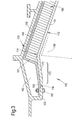
- a turbomachine casing assembly 100 comprises a first casing element 110 and a second casing element 120.
- the first casing element 110 at least partially encases and surrounds one or more rotating aerofoil structures 130. These aerofoil structures 130 may comprise blades of a turbomachine, in particular compressor fan blades.
- the second casing element 120 is disposed radially outward of the first casing element 110.
- the turbomachine casing assembly 100 may comprise a plurality of first casing elements 110 circumferentially disposed about a curve defined by the blade tip path of the one or more aerofoil structures of the turbomachine.
- the first and/or second casing elements 110, 120 may typically be metallic and may for example be formed of aluminium, titanium, steel or any other metal.
- the casing assembly 100 may be provided with an infill member 160, e.g. a structural and/or acoustic liner between the first and second casing elements 110, 120.
- the infill member 160 may be a frangible or crushable structure, such as an acoustic foam or honeycomb. Furthermore, there may be a gap 163 between the infill member 160 and the second casing element 120 (as shown in Figure 3 ), or the infill member 160 may abut both the first and second casing elements 110, 120 (not shown).
- the infill member 160 may be made from an Aluminium honeycomb or may be made from any other honeycomb formed from other metals or resins. For example, one preferred non-metallic material is Nomex (a registered trademark for flame resistant meta-Aramid material).
- the Aramid sheet may be saturated with a Phenolic resin.
- the honeycomb may be replaced by a metal or synthetic foam.
- Each first casing element 110 may comprise a curved panel, which may be in the form of an attrition liner 112.
- An exemplary material for the attrition layer is an epoxy resin, which may be curable at room temperature.
- the attrition liner 112 may provide a surface against which the aerofoil structure 130 is able to rub and cut a path for itself. For example, the fan blades may rub against the attrition liner 112 and form a seal during normal engine operation.
- the attrition liner 112 may be attached to a backing tray or septum layer 114. Each liner 112 and septum layer 114 may form an arc of a sector such that the fan casing assembly comprises multiple sectors.
- the septum layer 114 may be metallic or may be formed from a carbon fibre or glass fibre reinforced polymer.
- the septum layer may provide stabilisation for the infill member 160 and may provide a backing sheet for the attrition liner 112.
- the combination of attrition layer 112 and septum layer 114 may form a load spreader such that ice or fan blade-off loads are distributed as far across the infill member 160 as possible.
- the septum layer 114 may be axially longer than the attrition liner 112 and as such the septum layer 114 and attrition layer 112 may form an abutment shoulder 116 where the septum layer overlaps the attrition layer.
- the abutment shoulder 116 may be formed at a forward end of the first casing element 110.
- the septum layer and attrition layer may also form an abutment shoulder at a rearward end of the first casing element 110.
- the second casing element 120 may comprise an aerofoil structure retaining feature, for example a hooked portion 122.
- the hooked portion 122 may extend radially inwardly and then axially in a rearward direction.
- the abutment shoulder 116 may interlock with the hooked portion 122 such that the septum layer 114 is disposed radially between the hooked portion 122 and the remainder of the second casing element 120.
- the infill member 160 may terminate at a point set back from an end or edge of the first casing element 110, e.g. an edge of the septum layer 114 or attrition layer 112.
- a termination, e.g. an end wall 161 of the infill member 160 may be set back from an edge of the first casing element such that a void 162 may be provided between the first and second casing elements 110, 120.
- the infill member 160 and void 162 may be provided between first and second portions respectively of the first and second casing elements 110, 120.
- the first and second portions of the first and second casing elements may be axially set apart.
- the first and second portions of the first and second casing elements may be adjacent to one another, e.g. in an axial sense.
- the void may be filled with a further infill member.
- the further infill member may be weaker than the infill member 160.
- the first casing element may comprise a cantilever 170.
- the cantilever may be arranged in a region 172 between the edge of the first casing element 110 and a leading edge of the aerofoil structure 130.
- the cantilever 170 may be arranged such that upon failure of one of the rotating aerofoil structures 130, the cantilever bends into the void 162 provided between the first and second casing elements 110, 120.
- the length of the cantilever 170 may need to be large enough to provide purchase for the fan blade and/or develop enough bending moment to cause collapse of the cantilever material.
- the length of the cantilever 170 may be the distance from the aerofoil structure retaining feature 122 to the end 161 of the infill member 160.
- the length of the cantilever 170 may be the distance from the aerofoil structure retaining feature 122 to a point on the attrition liner 112 approximately opposite the leading edge at the tip of the aerofoil structure 130.
- the flexible cantilever 170 is generated by moving the end 161 of the infill member 160 rearward.
- the cantilever 170 may not be able to withstand the force associated with the buckling of the aerofoil structure 130, e.g. following a blade-off event.
- the cantilever region 172 may act as a 'trap door' allowing the aerofoil structure tip to enter and engage with the hook 122.
- the turbomachine casing assembly 100 may further comprise a backing layer or liner 150.
- the liner 150 may be affixed to the infill member 160 and/or the septum layer 114.
- the infill member 160 may be arranged between the liner 150 and the first casing element 110 in the first portion of the first and second casing elements 110, 120, e.g. in which the infill member 160 is present.
- the void 162 may be arranged between the liner 150 and the second casing element 120 in the second portion of the first and second casing elements 110, 120, e.g. in which the void 162 is present. Accordingly, the void 162 and infill member 160 may be separated by the liner 150 and the end wall 161 of the infill member 160 may be covered by the liner 150.
- the liner 150 may be omitted and the termination of the infill member 160 may be defined by the end wall 161 itself.
- the liner 150 may be formed from a carbon fibre or glass fibre reinforced polymer.
- the liner 150 may provide structural stiffness to the casing assembly and may also provide locations for attachment to the engine structure. In the case that a liner 150 is provided, the stiffness of the liner 150 may be selected to provide a desired radial stiffness both in a local and global (e.g. hoop) sense.
- the turbomachine casing assembly 100 may further comprise a fastener 180 arranged to connect the first casing 110 element to the second casing element 120.
- the fastener 180 may connect the first casing element 110 to the aerofoil structure retaining feature 122.
- the fastener 180 may connect to the first casing element 110 via the septum layer 114 and/or liner 150.
- the fastener 180 may comprise a nut and bolt assembly, which may be located in holes provided in the aerofoil structure retaining feature 122, septum layer 114 and/or liner 150.
- the fastener 180 may be frangible so that it breaks in the event of a blade-off.
- the performance of the cantilever 170 may be independent of the angle of the liner 150 or the end wall 161 at the termination of the infill member 160.
- the fastener 180 may fail in preference to the infill member 160. Nevertheless, the angle of the infill member end wall 161 and any local support from the infill member 160 may be selected to ensure that the fastener 180 fails before the infill member 160.
- a benefit of the casing assembly 100 disclosed herein is that the cantilever 170 is weaker than previous arrangements and therefore more closely matched to the reduced load provided by the ice shedding process in this area. Furthermore, since the cantilever 170 is weaker than the previous arrangement, it may not be capable of withstanding the blade-off loads. As a collapsing aerofoil structure passes over the cantilever region 172, the liner structure may readily collapse and allow the aerofoil structure tip to engage with the hook 122. This may assist the current weight reduced fan blade designs to satisfactorily penetrate the liner and engage the hook following a fan blade-off event.
- the casing assembly disclosed herein is equally applicable to solid and hollow fan blades and may be used with light-weight (hollow line-core or solid composite) fan blades.
- the casing assembly may also be used with aerofoil structures, e.g. fan blades, comprising a principal load-carrying member at the front of the aerofoil structure such as a picture frame or metallic sheath.
- aerofoil structures e.g. fan blades, comprising a principal load-carrying member at the front of the aerofoil structure such as a picture frame or metallic sheath.
- the present disclosure may also be applied to swept or unswept aerofoil structures.
- the present example allows a fan blade to penetrate the first casing element at a forward point (in the case of a blade off event), whilst remaining rigid to ice impact at the rear.
- the competing requirements of fan blade ice shedding loads and fan blade off loads may be accommodated in a way that was not previously possible. The manner in which this is done allows for the potential to tune the casing assembly to correctly service each requirement and does so whilst saving weight and easing manufacture.
- the casing assembly of the present disclosure may therefore be lighter. Furthermore, by removing the infill member and the associated materials, unnecessary material is being removed that is just not needed to cope with the ice impact loads and therefore unnecessary margin is not being carried.
- the casing assembly of the present disclosure may also be easier to manufacture.
- the position of the infill member end wall may be chosen to reduce the variation required in the infill member to accommodate the casing profile.
- the infill member may be made a constant thickness along the main cone of the casing assembly.
- a further advantage of the present disclosure may be adjustability and the performance of the casing assembly may be tuned to the particular installation.
- the thickness of one or more of the liner or septum layer may be varied.
- the size and number of fasteners may also be varied. In this way, the differing requirements of the fan blade ice shedding loading and the fan blade-off loads may be designed for accurately over a multiplicity of actual installations.
Landscapes
- Engineering & Computer Science (AREA)
- Mechanical Engineering (AREA)
- General Engineering & Computer Science (AREA)
- Chemical & Material Sciences (AREA)
- Combustion & Propulsion (AREA)
- Structures Of Non-Positive Displacement Pumps (AREA)
Applications Claiming Priority (1)
| Application Number | Priority Date | Filing Date | Title |
|---|---|---|---|
| GBGB1103682.9A GB201103682D0 (en) | 2011-03-04 | 2011-03-04 | A turbomachine casing assembly |
Publications (2)
| Publication Number | Publication Date |
|---|---|
| EP2495400A2 true EP2495400A2 (fr) | 2012-09-05 |
| EP2495400A3 EP2495400A3 (fr) | 2015-03-11 |
Family
ID=43923183
Family Applications (2)
| Application Number | Title | Priority Date | Filing Date |
|---|---|---|---|
| EP12152503.4A Not-in-force EP2495401B1 (fr) | 2011-03-04 | 2012-01-25 | Ensemble de carter de turbomachine |
| EP12152501.8A Withdrawn EP2495400A3 (fr) | 2011-03-04 | 2012-01-25 | Ensemble de carter de turbomachine |
Family Applications Before (1)
| Application Number | Title | Priority Date | Filing Date |
|---|---|---|---|
| EP12152503.4A Not-in-force EP2495401B1 (fr) | 2011-03-04 | 2012-01-25 | Ensemble de carter de turbomachine |
Country Status (3)
| Country | Link |
|---|---|
| US (5) | US8888439B2 (fr) |
| EP (2) | EP2495401B1 (fr) |
| GB (4) | GB201103682D0 (fr) |
Cited By (12)
| Publication number | Priority date | Publication date | Assignee | Title |
|---|---|---|---|---|
| WO2014137411A1 (fr) * | 2013-03-04 | 2014-09-12 | Rolls-Royce Corporation | Ensemble de chemisage de piste de pales de soufflante comportant un élément ressort |
| WO2014143188A1 (fr) * | 2013-03-11 | 2014-09-18 | Rolls-Royce Corporation | Chemisage de piste de ventilateur conçu pour un rendement au voisinage d'un crochet de carter de ventilateur |
| CN104603400A (zh) * | 2012-09-06 | 2015-05-06 | 通用电气公司 | 耐摩擦风扇壳 |
| EP2876262A1 (fr) * | 2013-11-22 | 2015-05-27 | Rolls-Royce plc | Moteur à turbine à gaz |
| EP2846005A3 (fr) * | 2013-09-03 | 2015-07-01 | MTU Aero Engines GmbH | Dispositif d'absorption d'énergie, turbomachine et procédé d'absorption d'énergie |
| EP2902593A1 (fr) * | 2014-02-03 | 2015-08-05 | Rolls-Royce plc | Système de confinement de soufflante dans un moteur à turbine à gaz axial |
| EP2902592A1 (fr) * | 2014-01-31 | 2015-08-05 | Rolls-Royce plc | Moteur à turbine à gaz |
| EP2932052A4 (fr) * | 2012-12-14 | 2016-02-17 | United Technologies Corp | Boîtier de confinement de ventilateur doté d'un chemisage conforme thermiquement |
| US9683490B2 (en) | 2013-11-21 | 2017-06-20 | Rolls-Royce Plc | Pivoting fan track liner for blade retainment |
| EP3293366A1 (fr) * | 2016-09-06 | 2018-03-14 | Rolls-Royce Corporation | Boîtier de confinement de soufflante renforcé pour un moteur à turbine à gaz |
| US10641287B2 (en) | 2016-09-06 | 2020-05-05 | Rolls-Royce Corporation | Fan containment case for a gas turbine engine |
| CN114483306A (zh) * | 2020-11-13 | 2022-05-13 | 中国航发商用航空发动机有限责任公司 | 一种风扇包容机匣及航空发动机 |
Families Citing this family (37)
| Publication number | Priority date | Publication date | Assignee | Title |
|---|---|---|---|---|
| US7665960B2 (en) | 2006-08-10 | 2010-02-23 | United Technologies Corporation | Turbine shroud thermal distortion control |
| GB201103682D0 (en) * | 2011-03-04 | 2011-04-20 | Rolls Royce Plc | A turbomachine casing assembly |
| GB201120557D0 (en) | 2011-11-30 | 2012-01-11 | Rolls Royce Plc | A turbomachine casing assembly |
| FR2995949B1 (fr) * | 2012-09-25 | 2018-05-25 | Safran Aircraft Engines | Carter de turbomachine |
| US9366185B2 (en) | 2012-09-28 | 2016-06-14 | United Technologies Corporation | Flexible connection between a wall and a case of a turbine engine |
| DE102013207452A1 (de) * | 2013-04-24 | 2014-11-13 | MTU Aero Engines AG | Gehäuseabschnitt einer Turbomaschinenverdichter- oder Turbomaschinenturbinenstufe |
| US10221718B2 (en) | 2013-09-09 | 2019-03-05 | United Technologies Corporation | Fan cases and manufacture methods |
| GB201405388D0 (en) * | 2014-03-26 | 2014-05-07 | Rolls Royce Plc | Turbomachine fan casing assembly |
| GB201405496D0 (en) * | 2014-03-27 | 2014-05-14 | Rolls Royce Plc | Linear assembly |
| GB201408688D0 (en) | 2014-05-16 | 2014-07-02 | Rolls Royce Plc | Gas turbine engine |
| AT516322B1 (de) * | 2014-10-10 | 2017-04-15 | Facc Ag | Fangehäuse für ein Flugzeugtriebwerk |
| GB2539217B (en) * | 2015-06-09 | 2020-02-12 | Rolls Royce Plc | Fan casing assembly |
| FR3040737B1 (fr) * | 2015-09-04 | 2017-09-22 | Snecma | Ensemble propulsif muni de parties de carter decouplables |
| US10077782B2 (en) * | 2015-09-30 | 2018-09-18 | Siemens Aktiengesellschaft | Adaptive blade tip seal assembly |
| US10082152B2 (en) * | 2015-09-30 | 2018-09-25 | Siemens Aktiengsellschaft | Gas turbine compressor with adaptive blade tip seal assembly |
| US10260522B2 (en) * | 2016-05-19 | 2019-04-16 | Rolls-Royce Corporation | Liner system |
| US10487684B2 (en) | 2017-03-31 | 2019-11-26 | The Boeing Company | Gas turbine engine fan blade containment systems |
| US10550718B2 (en) | 2017-03-31 | 2020-02-04 | The Boeing Company | Gas turbine engine fan blade containment systems |
| US10436061B2 (en) | 2017-04-13 | 2019-10-08 | General Electric Company | Tapered composite backsheet for use in a turbine engine containment assembly |
| US10662813B2 (en) | 2017-04-13 | 2020-05-26 | General Electric Company | Turbine engine and containment assembly for use in a turbine engine |
| US10677261B2 (en) * | 2017-04-13 | 2020-06-09 | General Electric Company | Turbine engine and containment assembly for use in a turbine engine |
| US20180347585A1 (en) * | 2017-06-01 | 2018-12-06 | Rolls-Royce Corporation | Fan track liner assembly |
| US10940955B2 (en) * | 2017-11-27 | 2021-03-09 | Rohr, Inc. | Acoustic panel with structural septum |
| GB2575296B (en) * | 2018-07-04 | 2022-06-29 | Rolls Royce Plc | Method and tooling for manufacturing a fan case assembly |
| US12044167B2 (en) * | 2018-07-23 | 2024-07-23 | Rtx Corporation | Stator configuration for gas turbine engine |
| US11401862B2 (en) | 2018-07-23 | 2022-08-02 | Raytheon Technologies Corporation | Stator configuration for gas turbine engine |
| GB201816990D0 (en) * | 2018-10-18 | 2018-12-05 | Rolls Royce Plc | Debris retention |
| GB201816989D0 (en) * | 2018-10-18 | 2018-12-05 | Rolls Royce Plc | Debris retention |
| EP3885537A1 (fr) | 2020-03-26 | 2021-09-29 | Unison Industries LLC | Système de confinement de démarrage de turbine à air et procédé de fabrication d´un tel système |
| EP3885539A1 (fr) | 2020-03-26 | 2021-09-29 | Unison Industries LLC | Démarreur à turbine à air et procédé de confinement d'une turbine d'un démarreur à turbine à air |
| WO2022208801A1 (fr) * | 2021-03-31 | 2022-10-06 | 川崎重工業株式会社 | Ensemble carter de soufflante destiné à un turboréacteur à double flux |
| US11346242B1 (en) * | 2021-06-10 | 2022-05-31 | William Maxwell | Retaining ejected gas turbine blades |
| US11852022B2 (en) * | 2021-06-10 | 2023-12-26 | William Maxwell | Retaining ejected gas turbine blades |
| US11788549B2 (en) | 2021-10-04 | 2023-10-17 | General Electric Company | Turbofan blade blocking apparatus |
| US12071858B2 (en) * | 2021-10-13 | 2024-08-27 | General Electric Company | Fire retardant engine casing apparatus |
| US12158076B1 (en) | 2023-07-07 | 2024-12-03 | Pratt & Whitney Canada Corp. | Local stiffening for gas turbine engine casing |
| US12398656B1 (en) * | 2024-05-01 | 2025-08-26 | Pratt & Whitney Canada Corp. | Containment ring for gas turbine engine |
Family Cites Families (24)
| Publication number | Priority date | Publication date | Assignee | Title |
|---|---|---|---|---|
| US4149824A (en) * | 1976-12-23 | 1979-04-17 | General Electric Company | Blade containment device |
| FR2467978A1 (fr) * | 1979-10-23 | 1981-04-30 | Snecma | Dispositif de retention pour carter de compresseur d'une turbomachine |
| FR2574476B1 (fr) * | 1984-12-06 | 1987-01-02 | Snecma | Carter de retention pour soufflante de turboreacteur |
| CA2042198A1 (fr) * | 1990-06-18 | 1991-12-19 | Stephen C. Mitchell | Ecran protecteur contre les projectiles |
| FR2713709B1 (fr) * | 1993-12-08 | 1996-01-12 | Snecma | Paroi de turbomachine comprenant un corps d'étanchéité. |
| US5431532A (en) * | 1994-05-20 | 1995-07-11 | General Electric Company | Blade containment system |
| GB9605284D0 (en) * | 1996-03-13 | 1996-05-15 | Rolls Royce Plc | Gas turbine engine casing construction |
| US6206631B1 (en) * | 1999-09-07 | 2001-03-27 | General Electric Company | Turbomachine fan casing with dual-wall blade containment structure |
| GB9922619D0 (en) | 1999-09-25 | 1999-11-24 | Rolls Royce Plc | A gas turbine engine blade containment assembly |
| US6227794B1 (en) * | 1999-12-16 | 2001-05-08 | Pratt & Whitney Canada Corp. | Fan case with flexible conical ring |
| GB0116988D0 (en) * | 2000-08-11 | 2001-09-05 | Rolls Royce Plc | A gas turbine engine blade containment assembly |
| US6619913B2 (en) | 2002-02-15 | 2003-09-16 | General Electric Company | Fan casing acoustic treatment |
| US6767625B2 (en) * | 2002-12-30 | 2004-07-27 | Owens Corning Fiberglas Technology, Inc. | Method for making a charge of moldable material |
| GB2407343B (en) * | 2003-10-22 | 2006-04-19 | Rolls Royce Plc | An acoustic liner for a gas turbine engine casing |
| GB0501284D0 (en) | 2005-01-21 | 2005-03-02 | Rolls Royce Plc | Aerofoil containment structure |
| GB2427436B (en) | 2005-06-23 | 2007-11-28 | Rolls Royce Plc | Fan duct blade containment assembly |
| DE102005055050B4 (de) * | 2005-11-16 | 2007-09-27 | Ifc Composite Gmbh | Segmentierte Faserverbund-Blattfeder und Verfahren zur Herstellung derselben |
| DE102006036648A1 (de) | 2006-08-03 | 2008-02-07 | Rolls-Royce Deutschland Ltd & Co Kg | Eisschlagschutzring für das Fangehäuse einer Fluggasturbine |
| GB0813821D0 (en) * | 2008-07-29 | 2008-09-03 | Rolls Royce Plc | A fan casing for a gas turbine engine |
| US8092169B2 (en) * | 2008-09-16 | 2012-01-10 | United Technologies Corporation | Integrated inlet fan case |
| GB2469447B (en) | 2009-04-15 | 2011-03-09 | Rolls Royce Plc | Gas turbine engine casing assembly |
| GB0914523D0 (en) * | 2009-08-20 | 2009-09-30 | Rolls Royce Plc | A turbomachine casing assembly |
| GB0916823D0 (en) * | 2009-09-25 | 2009-11-04 | Rolls Royce Plc | Containment casing for an aero engine |
| GB201103682D0 (en) * | 2011-03-04 | 2011-04-20 | Rolls Royce Plc | A turbomachine casing assembly |
-
2011
- 2011-03-04 GB GBGB1103682.9A patent/GB201103682D0/en not_active Ceased
-
2012
- 2012-01-25 EP EP12152503.4A patent/EP2495401B1/fr not_active Not-in-force
- 2012-01-25 GB GB1201176.3A patent/GB2488629A/en not_active Withdrawn
- 2012-01-25 EP EP12152501.8A patent/EP2495400A3/fr not_active Withdrawn
- 2012-01-25 US US13/358,010 patent/US8888439B2/en not_active Expired - Fee Related
- 2012-01-25 GB GBGB1201180.5A patent/GB201201180D0/en not_active Ceased
- 2012-01-25 GB GB1201174.8A patent/GB2488628A/en not_active Withdrawn
- 2012-01-25 US US13/358,080 patent/US8926263B2/en active Active
-
2013
- 2013-01-15 US US13/741,656 patent/US9222368B2/en not_active Expired - Fee Related
- 2013-01-15 US US13/741,728 patent/US9206706B2/en not_active Expired - Fee Related
- 2013-01-15 US US13/741,842 patent/US20140064949A1/en not_active Abandoned
Non-Patent Citations (1)
| Title |
|---|
| None |
Cited By (22)
| Publication number | Priority date | Publication date | Assignee | Title |
|---|---|---|---|---|
| CN104603400B (zh) * | 2012-09-06 | 2017-03-08 | 通用电气公司 | 耐摩擦风扇壳 |
| CN104603400A (zh) * | 2012-09-06 | 2015-05-06 | 通用电气公司 | 耐摩擦风扇壳 |
| JP2015531444A (ja) * | 2012-09-06 | 2015-11-02 | ゼネラル・エレクトリック・カンパニイ | 耐摩擦性ファンケース |
| EP2932052A4 (fr) * | 2012-12-14 | 2016-02-17 | United Technologies Corp | Boîtier de confinement de ventilateur doté d'un chemisage conforme thermiquement |
| US9482111B2 (en) | 2012-12-14 | 2016-11-01 | United Technologies Corporation | Fan containment case with thermally conforming liner |
| WO2014137411A1 (fr) * | 2013-03-04 | 2014-09-12 | Rolls-Royce Corporation | Ensemble de chemisage de piste de pales de soufflante comportant un élément ressort |
| WO2014143188A1 (fr) * | 2013-03-11 | 2014-09-18 | Rolls-Royce Corporation | Chemisage de piste de ventilateur conçu pour un rendement au voisinage d'un crochet de carter de ventilateur |
| US10024191B2 (en) | 2013-03-11 | 2018-07-17 | Rolls-Royce Corporation | Fan track liner designed to yield next to fan case hook |
| EP2846005A3 (fr) * | 2013-09-03 | 2015-07-01 | MTU Aero Engines GmbH | Dispositif d'absorption d'énergie, turbomachine et procédé d'absorption d'énergie |
| US9683490B2 (en) | 2013-11-21 | 2017-06-20 | Rolls-Royce Plc | Pivoting fan track liner for blade retainment |
| EP2876262A1 (fr) * | 2013-11-22 | 2015-05-27 | Rolls-Royce plc | Moteur à turbine à gaz |
| US9677570B2 (en) | 2013-11-22 | 2017-06-13 | Rolls-Royce Plc | Gas turbine engine |
| EP2902592A1 (fr) * | 2014-01-31 | 2015-08-05 | Rolls-Royce plc | Moteur à turbine à gaz |
| US9797269B2 (en) | 2014-01-31 | 2017-10-24 | Rolls-Royce Plc | Gas turbine engine |
| EP2902593A1 (fr) * | 2014-02-03 | 2015-08-05 | Rolls-Royce plc | Système de confinement de soufflante dans un moteur à turbine à gaz axial |
| US9677417B2 (en) | 2014-02-03 | 2017-06-13 | Rolls-Royce Plc | Gas turbine engine |
| EP3293366A1 (fr) * | 2016-09-06 | 2018-03-14 | Rolls-Royce Corporation | Boîtier de confinement de soufflante renforcé pour un moteur à turbine à gaz |
| EP3293365A1 (fr) * | 2016-09-06 | 2018-03-14 | Rolls-Royce Corporation | Boîtier de confinement de soufflante renforcé pour un moteur à turbine à gaz |
| US10641287B2 (en) | 2016-09-06 | 2020-05-05 | Rolls-Royce Corporation | Fan containment case for a gas turbine engine |
| US10655500B2 (en) | 2016-09-06 | 2020-05-19 | Rolls-Royce Corporation | Reinforced fan containment case for a gas turbine engine |
| CN114483306A (zh) * | 2020-11-13 | 2022-05-13 | 中国航发商用航空发动机有限责任公司 | 一种风扇包容机匣及航空发动机 |
| CN114483306B (zh) * | 2020-11-13 | 2023-09-01 | 中国航发商用航空发动机有限责任公司 | 一种风扇包容机匣及航空发动机 |
Also Published As
| Publication number | Publication date |
|---|---|
| US8888439B2 (en) | 2014-11-18 |
| US20140072426A1 (en) | 2014-03-13 |
| GB201201174D0 (en) | 2012-03-07 |
| US20120224958A1 (en) | 2012-09-06 |
| GB201103682D0 (en) | 2011-04-20 |
| US8926263B2 (en) | 2015-01-06 |
| GB2488628A (en) | 2012-09-05 |
| US9206706B2 (en) | 2015-12-08 |
| EP2495401A2 (fr) | 2012-09-05 |
| GB2488629A (en) | 2012-09-05 |
| EP2495400A3 (fr) | 2015-03-11 |
| US20120224949A1 (en) | 2012-09-06 |
| EP2495401A3 (fr) | 2015-03-11 |
| GB201201176D0 (en) | 2012-03-07 |
| US20140064949A1 (en) | 2014-03-06 |
| US9222368B2 (en) | 2015-12-29 |
| GB201201180D0 (en) | 2012-03-07 |
| US20130189095A1 (en) | 2013-07-25 |
| EP2495401B1 (fr) | 2016-06-01 |
Similar Documents
| Publication | Publication Date | Title |
|---|---|---|
| US8926263B2 (en) | Turbomachine casing assembly | |
| US8438857B2 (en) | Aircraft engine inlet having zone of deformation | |
| US8894349B2 (en) | Turbomachine casing assembly | |
| EP2388441B1 (fr) | Carter de soufflante avec éléments de frottement | |
| US10385870B2 (en) | Composite fan inlet blade containment | |
| US7506838B2 (en) | Air intake structure for aircraft engine | |
| US9085992B2 (en) | Turbomachine casing assembly | |
| US20150275689A1 (en) | Composite fan containment case assembly | |
| EP3246532B1 (fr) | Système de revêtement intérieur pour un carter de soufflante | |
| EP2971601B1 (fr) | Agencement de virole pour un carter de soufflante | |
| US9677570B2 (en) | Gas turbine engine | |
| US9957835B2 (en) | Fan track liner assembly | |
| US9732626B2 (en) | Turbomachine casing assembly | |
| EP2902593B1 (fr) | Système de confinement de soufflante dans un moteur à turbine à gaz axial | |
| US10125631B2 (en) | Fan track liner assembly | |
| US20160176532A1 (en) | Propeller for an aircraft turbomachine, including a blade retaining structure through which the aerodynamic part of each blade passes | |
| US20210054762A1 (en) | Gas turbine engine fan bumper | |
| GB2471466A (en) | Fan casing for a turbofan gas turbine engine |
Legal Events
| Date | Code | Title | Description |
|---|---|---|---|
| PUAI | Public reference made under article 153(3) epc to a published international application that has entered the european phase |
Free format text: ORIGINAL CODE: 0009012 |
|
| AK | Designated contracting states |
Kind code of ref document: A2 Designated state(s): AL AT BE BG CH CY CZ DE DK EE ES FI FR GB GR HR HU IE IS IT LI LT LU LV MC MK MT NL NO PL PT RO RS SE SI SK SM TR |
|
| AX | Request for extension of the european patent |
Extension state: BA ME |
|
| PUAL | Search report despatched |
Free format text: ORIGINAL CODE: 0009013 |
|
| AK | Designated contracting states |
Kind code of ref document: A3 Designated state(s): AL AT BE BG CH CY CZ DE DK EE ES FI FR GB GR HR HU IE IS IT LI LT LU LV MC MK MT NL NO PL PT RO RS SE SI SK SM TR |
|
| AX | Request for extension of the european patent |
Extension state: BA ME |
|
| RIC1 | Information provided on ipc code assigned before grant |
Ipc: F01D 25/24 20060101ALI20150203BHEP Ipc: F02K 3/06 20060101ALI20150203BHEP Ipc: F01D 21/04 20060101AFI20150203BHEP Ipc: B64D 29/06 20060101ALI20150203BHEP |
|
| RAP1 | Party data changed (applicant data changed or rights of an application transferred) |
Owner name: ROLLS-ROYCE PLC |
|
| 17P | Request for examination filed |
Effective date: 20150910 |
|
| RBV | Designated contracting states (corrected) |
Designated state(s): AL AT BE BG CH CY CZ DE DK EE ES FI FR GB GR HR HU IE IS IT LI LT LU LV MC MK MT NL NO PL PT RO RS SE SI SK SM TR |
|
| STAA | Information on the status of an ep patent application or granted ep patent |
Free format text: STATUS: EXAMINATION IS IN PROGRESS |
|
| 17Q | First examination report despatched |
Effective date: 20180403 |
|
| STAA | Information on the status of an ep patent application or granted ep patent |
Free format text: STATUS: THE APPLICATION IS DEEMED TO BE WITHDRAWN |
|
| 18D | Application deemed to be withdrawn |
Effective date: 20180814 |