EP2495448A2 - Elément orientant l'écoulement pour une pompe et pompe - Google Patents
Elément orientant l'écoulement pour une pompe et pompe Download PDFInfo
- Publication number
- EP2495448A2 EP2495448A2 EP12157677A EP12157677A EP2495448A2 EP 2495448 A2 EP2495448 A2 EP 2495448A2 EP 12157677 A EP12157677 A EP 12157677A EP 12157677 A EP12157677 A EP 12157677A EP 2495448 A2 EP2495448 A2 EP 2495448A2
- Authority
- EP
- European Patent Office
- Prior art keywords
- pump
- flow
- guiding device
- vanes
- ring
- Prior art date
- Legal status (The legal status is an assumption and is not a legal conclusion. Google has not performed a legal analysis and makes no representation as to the accuracy of the status listed.)
- Granted
Links
Images

Classifications
-
- F—MECHANICAL ENGINEERING; LIGHTING; HEATING; WEAPONS; BLASTING
- F04—POSITIVE - DISPLACEMENT MACHINES FOR LIQUIDS; PUMPS FOR LIQUIDS OR ELASTIC FLUIDS
- F04D—NON-POSITIVE-DISPLACEMENT PUMPS
- F04D29/00—Details, component parts, or accessories
- F04D29/40—Casings; Connections of working fluid
- F04D29/42—Casings; Connections of working fluid for radial or helico-centrifugal pumps
- F04D29/44—Fluid-guiding means, e.g. diffusers
- F04D29/46—Fluid-guiding means, e.g. diffusers adjustable
- F04D29/466—Fluid-guiding means, e.g. diffusers adjustable especially adapted for liquid fluid pumps
- F04D29/468—Fluid-guiding means, e.g. diffusers adjustable especially adapted for liquid fluid pumps adjusting flow cross-section, otherwise than by using adjustable stator blades
-
- F—MECHANICAL ENGINEERING; LIGHTING; HEATING; WEAPONS; BLASTING
- F04—POSITIVE - DISPLACEMENT MACHINES FOR LIQUIDS; PUMPS FOR LIQUIDS OR ELASTIC FLUIDS
- F04D—NON-POSITIVE-DISPLACEMENT PUMPS
- F04D29/00—Details, component parts, or accessories
- F04D29/40—Casings; Connections of working fluid
- F04D29/42—Casings; Connections of working fluid for radial or helico-centrifugal pumps
- F04D29/44—Fluid-guiding means, e.g. diffusers
- F04D29/445—Fluid-guiding means, e.g. diffusers especially adapted for liquid pumps
- F04D29/448—Fluid-guiding means, e.g. diffusers especially adapted for liquid pumps bladed diffusers
-
- F—MECHANICAL ENGINEERING; LIGHTING; HEATING; WEAPONS; BLASTING
- F05—INDEXING SCHEMES RELATING TO ENGINES OR PUMPS IN VARIOUS SUBCLASSES OF CLASSES F01-F04
- F05D—INDEXING SCHEME FOR ASPECTS RELATING TO NON-POSITIVE-DISPLACEMENT MACHINES OR ENGINES, GAS-TURBINES OR JET-PROPULSION PLANTS
- F05D2240/00—Components
- F05D2240/10—Stators
- F05D2240/12—Fluid guiding means, e.g. vanes
Definitions
- the invention relates to a Strömungsleit adopted for a pump, namely an impeller radial pump, and a pump with such a flow guide therein.
- the invention has for its object to provide an aforementioned Strömungsleit adopted and a pump provided with it, can be avoided with the problems of the prior art and in particular with low manufacturing and assembly costs optimally working flow guide can be created in a pump.
- the flow guiding device is designed to be arranged in a pump chamber of an impeller radial pump.
- an impeller for conveying the fluid or for discharging the fluid in the radial direction rotates out of the impeller.
- the fluid flow in the pump chamber and around to a pump outlet.
- the flow-guiding device should be arranged radially outside the impeller and circulate annularly around it. It has a circumferential support ring. On the support ring either a continuous flow lip or a plurality of individual vanes may be arranged.
- the flow lip or guide vanes are formed so elastically or movably that their angle of attack changes depending on the strength of the fluid flow.
- an angle of attack is more in the radial direction and is relatively large, preferably the angle of attack is 75 ° to 90 °. So should be directed as far as possible or directly against the chamber wall, the entire fluid flow.
- the angle of attack becomes smaller, with the flow lip or guide vanes elastically bending or moving at least in regions relative to the longitudinal central axis of the pump.
- the angle of attack between 20 ° and 60 ° to the longitudinal central axis of the pump can be, preferably about 30 ° to 40 °. This means that the fluid flow is not More so strongly directed against the chamber wall, since it flows more strongly anyway and thus also flows more strongly against the chamber wall. Furthermore, then the delivery rate of the pump should not be unnecessarily limited by a standing too much in the fluid flow flow lip or vanes.
- the flow lip or the guide vanes are inclined towards the pump outlet from the carrier ring.
- they effect a steering of the fluid flow both toward the chamber wall and towards the pump outlet.
- the flow lip or the guide vanes are indeed arranged radially outside of the impeller in the pump. However, they should not be arranged directly in the fluid flow discharged from the impeller, but preferably at the edge thereof, in particular opposite of a pump bottom. On the one hand, their flow resistance is low and, on the other hand, they can better direct the entire fluid flow, in particular between themselves and the pump bottom.
- the support ring is seen along the longitudinal center axis of the pump is arranged slightly above the impeller.
- the support ring is arranged on an inner wall of the pump chamber and advantageously attached thereto, for example clamped or latched.
- the flow lip or the guide vanes are in the radial direction outwardly from the support ring in the manner described above.
- the support ring is connected by means of radially extending retaining webs with a circumferential retaining ring.
- the retaining ring may also be section or part of another component, for example a circumferential ring seal. Retaining webs and retaining ring or ring seal can be produced together in multi-component injection molding technology.
- the holding webs extend substantially radially outwards and the retaining ring has a larger diameter than the carrier ring.
- the flow lip or vanes likewise protrude from a radially inner support ring, but this in turn is fastened radially on the outside, in particular close to an outer edge of the pump chamber, by means of the retaining webs.
- a lighter attachment can be done or, in the case of a unit with said circumferential seal ring, a single component perform several functions.
- a circumferentially closed flow lip is provided on the carrier ring, which runs approximately uniformly.
- it has constant width and cross-section in the circumferential direction.
- it is designed so that it is elastic or movable around the support ring and this no articulated movable part is necessary. This is possible above all by production from an elastic plastic or elastomer.
- the thickness in the radial course it is possible to achieve the respective turn or mobility to change the aforementioned angle of attack. Therefore, it is considered advantageous here if the flow lip becomes thinner outward in the radial course, starting from a slightly greater thickness on the inside. For example, the thickness can be halved.
- a plurality of guide vanes are provided. These are narrow and elongated in the circumferential direction and have an approximately rectangular area. Thus, in their entirety they also form a kind of circumferential ring similar to the above-described flow lip.
- the guide vanes have a cross-section that remains constant in the circumferential direction, but which tapers in the radial direction from the inside outward.
- a factor of rejuvenation can range from 1.5 to 3. Either can be achieved by this taper, similar to the above-described flow lip, that at higher fluid flow radially outwardly mounted individual vanes fold more radially outward and thus give the smaller angle of attack at a stronger fluid flow.
- the mobility is a purely inherent property of the vanes.
- the guide vanes are movable about an axis.
- this axis is annular or runs along the carrier ring.
- Either to individual vanes are provided with a Drehachslagerung on the support ring, for example by short stub axle of the vane on the one hand or on the other hand support the supporting web projecting and engage in short mounting holes on the holding web on the one hand or the vane on the other.
- a pivotal movement counteracting resistance can be created.
- the carrier ring is at least partially elastic, so that no multiple or articulated movable parts are needed.
- the support ring for the vanes in Area formed between the guide blade and retaining web made of elastic or rubber-elastic material, namely left and right of each vane.
- the holding bridge in turn may consist of sturdy material.
- guide vanes made of elastic material or their narrowing towards the radial outer area a greater folding or moving can be achieved towards the smaller angles of incidence.
- each vane is particularly advantageously fastened with a corner region to exactly one retaining web, which can preferably be done by molding or injection molding, in particular in the abovementioned multi-component injection molding technique.
- a guide blade which is mounted or fastened only at a corner region can twist or rotate along its longitudinal axis in the circumferential direction. This is less close to the connection with the holding web, whereby the torsion increases with increasing distance from the corner region.
- the torsion may be at an angle of about 5 ° to 30 ° or even 45 °, depending on the magnitude of the fluid flow. It can be reinforced by reducing the thickness in the direction away from the retaining bar. Under certain circumstances, it may even be provided that the bending or tilting of the guide vanes in the longitudinal direction of the guide blade in the circumferential direction is limited by a stop on the pump housing, in particular on an inner wall.
- the guide vane in particular also by a thickness taper in the radial direction, also here, as described above, can bend more strongly in the case of a stronger fluid flow.
- a change in the angle of attack is also achieved near the retaining bar.
- a factor of thickness rejuvenation can be 1.5 to 3.
- This twisting of the guide vanes not only generally reduces the angle of attack with a stronger fluid flow, but by turning or turning off the guide vanes in the longitudinal direction, an even better steering of the fluid flow can be achieved even with a large fluid flow, which also rotates.
- a plurality of guide vanes are arranged annularly, in particular five to twelve guide vanes. Due to the larger number, a somewhat finer subdivision in the circumferential direction can be provided for easier movability or twistability.
- the aforementioned holding webs have a flow-favorable profile in cross section.
- they can have a fluid flow opposing broad rounded front, which tapers towards the rear. As a result, the fluid flow is slowed down less.
- An aforementioned retaining ring can be provided in a pump according to the invention, for example in a region of the transition of the outer chamber wall to a pump bottom. There attachment under certain circumstances disturbs the fluid flow less.
- a circumferential annular seal together with the retaining ring can be provided here anyway between chamber wall and pump housing or pump bottom and made of elastic material. Due to the aforementioned multi-component spray technique, it can together with a vorteihaft radially inner retaining ring made of sturdy material be connected, from which in turn protrude the stable retaining webs. Thus, when assembling the pump only a single part needs to be installed, which can take over the functions of a seal on the one hand and a steering of the fluid flow on the other hand.
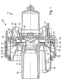
- Fig. 1 is a lateral longitudinal section of a pump 11 according to the invention shown with a pump housing 12 in which a pump chamber 13 with an outer chamber wall 14 is located.
- a pump housing 12 in which a pump chamber 13 with an outer chamber wall 14 is located.
- a pump chamber 13 with an outer chamber wall 14 is located.
- radial pump is for example from the EP 2150165 A2 known.
- a pump bottom 15 is further formed and a central axial tubular inlet 16, which merges into a pump cover 17, which in turn merges into an inner wall, which then leads to a lateral outlet 18.
- the inlet 16 leads to an over the pump bottom 15 in the usual manner mounted impeller 19. It is designed as a closed impeller 19 with a lower impeller disk 20, an upper impeller disk 21 and main vanes 23 therebetween. To convey fluid in the pump 11, the impeller 19 rotates and delivers fluid into the pumping chamber 13 radially and with velocity component in the circumferential direction.
- the chamber wall 14 is formed or heated in a manner not shown as a heating element, so that the flowing along its inner side fluid on the way to the outlet 18 with several revolutions flows along it and is heated. Also this is on the aforementioned EP 2150165 A2 directed.
- a flow guide 25 is provided, which extends in an annular manner around the area in the transition between pump cover 17 and upper impeller disc 21 at its outer edge.
- the flow guide 25 has on a rotating support ring 27 a plurality of vanes 29, which are shown in dashed lines depending on the angular position to better show their course. They form in this position, as it were, a continuation of the course of the upper impeller disk 21, which can be general and advantageous in this way. Shown is a position of the vanes 29 at medium fluid flow. Here, the position at an angle of about 50 ° to the dashed longitudinal center axis of the pump 11 forms a good compromise between the flow of the chamber wall 14 on the one hand and low flow resistance on the other. Finally, the delivery rate of the pump 11 should be affected as little as possible.
- the support ring 27 may be arranged on the one hand directly on the pump cover 17, either directly molded, glued or by latching or the like. attached.
- the support ring 27 is disposed on radially extending retaining webs whose training is even better seen in the following figures.
- These radially outwardly extending retaining webs 31 are molded onto a circumferential V-seal made of plastic or elastomer.
- the holding webs 31 are stable or consist of stable plastic material, so that they can hold the carrier ring 27 in as much as possible the same position. It is quite possible that the support ring 27, as can be seen, rests against the pump cover 17, under some circumstances even with a certain bias, for a safe investment.
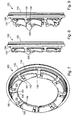
- a radially inner ring portion 34 is provided as the aforementioned retaining ring. It consists of the stable plastic, but like the rest of the flow guide 25 can be made in multi-component injection molding. He is in continuation of the pump bottom 15 radially outward.
- the ring portion 34 go eight evenly distributed retaining webs 31 and have slightly inclined radially inward. They too are made of the same sturdy plastic material.
- the holding webs 31 have at their inner ends on the rotating carrier ring 27 or wear this and are manufactured in one piece with it.
- the individual vanes 29 are integrally formed radially outward and slightly obliquely projecting.
- the vanes 29 have approximately rectangular shape and are slightly curved according to the diameter to a total of one To form a circular ring. This annulus of all the vanes 29 is interrupted only by the cutouts for the retaining webs 31.
- the pivoting of the guide vanes 29 about an approximately formed by the support ring 27 pivot axis takes place in that the support ring 27 is made of slightly twistable or total elastic material, for example, even of the same material as the sealing portions of the V-seal 33.
- Moving the Carrier ring 27 and its individual sections between the rigid retaining webs 31 in the radial or axial direction of the pump hardly takes place.
- In the axial direction of the support ring 27 could be moved at most by the pump bottom 15 away, in which case he just as, out Fig. 1 can be seen, is applied to the pump cover 17 and supported by this.
- a movement radially outward can hardly take place either, since the pressure exerted by the fluid flow flowing on the outside of the guide vanes 29 forces the latter to move radially inwards.
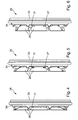
- Fig. 4 is again to see how the vanes 29 are employed in light fluid flow or in the production state.
- Fig. 5 their position at medium fluid flow is shown, which compares to Fig. 4 already much stronger, see also the to Fig. 1 aforementioned angle information.
- Fig. 6 If they are at a high or even maximum fluid flow, which can be generated in the pump 11, they are again employed.
- Fig. 1 can under certain circumstances even be provided that the guide vanes 29 create with strong or maximum fluid flow almost to the radially outwardly facing side of the pump cover 17 and thus almost almost completely out of the way.
- the one-piece mounting of the vanes 29 shown here has the great advantage over moving parts that it can be produced in one piece and eliminates additional assembly steps. Furthermore, storage problems caused by tolerances in the production or assembly as well as possible problems with an increasing stiffness of a storage with moving parts due to calcification odgl ..
- Fig. 7 is according to the Fig. 2 an alternative embodiment of a flow guide 125 shown.
- V-seal 133 with a radial inner ring portion 134 as a retaining ring are similar to Fig. 2 radially inwardly projecting retaining webs 131 provided or formed, which also consist of rigid material.
- a guide vane 129 is mounted or formed respectively to the right side by means of a storage section 132.
- the vanes 129 have a substantially rectangular shape similar to that of FIGS Fig. 2 to 6 , However, they are only quasi connected at their one corner via the storage section 132 with the rigid retaining bar 131. They themselves consist of a rather elastomeric, soft plastic material. Due to their shape, especially the out Fig. 7 to be seen to a free end 130 toward decreasing thickness, they are also elastic. Similar to the previously described flow guiding device, eight holding webs 131 with eight guide vanes 129 are provided thereon.
- FIG. 9 can be seen how the vanes 129 at high fluid flow, so accordingly Figure 6 , Are bent even more strongly and at the same time are even more bent or twisted to its free end 130 and the corner opposite the storage section 132. As a result, they assume a shape approximately corresponding to the left-hand dash line Fig. 1 Thus, in the case of a strong fluid flow, a larger flow cross section is released with somewhat weaker steering of the fluid to the chamber wall.
- the flow guide 125 achieves the goal of directing the pumped fluid in the pump depending on the fluid flow more or less strongly against the chamber wall with heating element.
- the advantage of the formation of the guide vanes 129 with one-sided storage or storage at a corner is that in with respect to Fig. 7 clockwise out of the plane of the plane circulating fluid such guide vanes 129 are streamlined, which are bent towards the free ends 130 toward stronger inside. So they are also bent slightly inwards in the direction of rotation of the fluid and thus reduce the flow resistance.
- a multi-component injection molding technique can also be used for the flow guiding device 125. This is true not only for the V-seal 133 and the radial inner ring portion 134 together with retaining webs 131 of more stable material.
- the storage portions 132 between holding bar 131 and vanes 129 may be made of softer or harder material. The same applies to the guide vanes 129 per se.
- a depression 136 is provided at each of the free ends 130 of the guide vanes 129 as a kind of additional cross-sectional tapering. These depressions 136 can also serve to effect a maximum contact with the vanes 129, a bearing on the pump cover 17, so that from this point, the vanes 129, although still possibly similar twist as those of the Fig. 2 to 6 , At least, however, they no longer bend in their longitudinal course.
- the holding webs 31 and 131 are formed with a streamlined cross-section, that is, not necessarily rectangular or sharp-edged as shown here for the sake of simplicity, but rounded.
Landscapes
- Engineering & Computer Science (AREA)
- Mechanical Engineering (AREA)
- General Engineering & Computer Science (AREA)
- Structures Of Non-Positive Displacement Pumps (AREA)
Priority Applications (1)
| Application Number | Priority Date | Filing Date | Title |
|---|---|---|---|
| PL12157677T PL2495448T3 (pl) | 2011-03-04 | 2012-03-01 | Urządzenie kierujące przepływem dla pompy i pompa |
Applications Claiming Priority (1)
| Application Number | Priority Date | Filing Date | Title |
|---|---|---|---|
| DE201110005139 DE102011005139B4 (de) | 2011-03-04 | 2011-03-04 | Strömungsleiteinrichtung für eine Pumpe und Pumpe |
Publications (3)
| Publication Number | Publication Date |
|---|---|
| EP2495448A2 true EP2495448A2 (fr) | 2012-09-05 |
| EP2495448A3 EP2495448A3 (fr) | 2014-01-01 |
| EP2495448B1 EP2495448B1 (fr) | 2018-08-22 |
Family
ID=45841205
Family Applications (1)
| Application Number | Title | Priority Date | Filing Date |
|---|---|---|---|
| EP12157677.1A Active EP2495448B1 (fr) | 2011-03-04 | 2012-03-01 | Elément orientant l'écoulement pour une pompe et pompe |
Country Status (6)
| Country | Link |
|---|---|
| US (1) | US9011091B2 (fr) |
| EP (1) | EP2495448B1 (fr) |
| DE (1) | DE102011005139B4 (fr) |
| ES (1) | ES2694581T3 (fr) |
| PL (1) | PL2495448T3 (fr) |
| TR (1) | TR201815705T4 (fr) |
Cited By (4)
| Publication number | Priority date | Publication date | Assignee | Title |
|---|---|---|---|---|
| CN103133392A (zh) * | 2013-03-06 | 2013-06-05 | 扬州大学 | 立式开敞式泵装置的活动空腔导水阀装置 |
| WO2015145386A1 (fr) * | 2014-03-26 | 2015-10-01 | I.R.C.A. S.P.A. Industria Resistenze Corazzate E Affini | Pompe centrifuge pour appareils ménagers |
| CN105508298A (zh) * | 2016-01-18 | 2016-04-20 | 中国联合工程公司 | 一种屏蔽电机主泵泵壳导流装置 |
| DE202019103660U1 (de) * | 2019-07-03 | 2020-10-06 | Borgwarner Inc. | Verstellmechanismus für einen Verdichter |
Families Citing this family (6)
| Publication number | Priority date | Publication date | Assignee | Title |
|---|---|---|---|---|
| ES2460369B1 (es) | 2012-11-12 | 2015-03-02 | Coprecitec Sl | Bomba de circulación de fluido adaptada para un aparato electrodoméstico |
| CN104235070A (zh) * | 2013-06-13 | 2014-12-24 | 德昌电机(深圳)有限公司 | 泵壳及具有该泵壳的泵 |
| WO2015100702A1 (fr) * | 2013-12-31 | 2015-07-09 | 宁波方太厨具有限公司 | Pompe à eau libre et son application |
| CN109058123A (zh) * | 2018-09-25 | 2018-12-21 | 彭定泽 | 一种水泵组合式导流结构 |
| DE102023203182A1 (de) * | 2023-04-05 | 2024-10-10 | BSH Hausgeräte GmbH | Haushalts-Geschirrspülmaschine |
| DE102023112929A1 (de) | 2023-05-16 | 2024-11-21 | E.G.O. Elektro-Gerätebau GmbH | Heizeinrichtung, Pumpe mit einer solchen Heizeinrichtung und wasserführendes Haushaltsgerät |
Citations (1)
| Publication number | Priority date | Publication date | Assignee | Title |
|---|---|---|---|---|
| EP2150165A2 (fr) | 2007-04-12 | 2010-02-10 | BSH Bosch und Siemens Hausgeräte GmbH | Pompe avec dispositif de chauffage |
Family Cites Families (13)
| Publication number | Priority date | Publication date | Assignee | Title |
|---|---|---|---|---|
| GB180823A (en) * | 1921-03-31 | 1922-06-08 | George Ure Reid | Improvements in centrifugal pumps |
| GB206825A (en) * | 1922-11-07 | 1924-01-10 | Escher Wyss Maschf Ag | An improved guide wheel for centrifugal pumps |
| US1988163A (en) * | 1930-03-21 | 1935-01-15 | Ingersoll Rand Co | Centrifugal pump |
| US2648195A (en) * | 1945-12-28 | 1953-08-11 | Rolls Royce | Centrifugal compressor for supercharging internal-combustion engines |
| FR921711A (fr) * | 1946-02-07 | 1947-05-16 | Diffuseur à réglage automatique pour pompes centrifuges | |
| FR2153796A5 (fr) * | 1971-09-24 | 1973-05-04 | Le Metalliches | |
| SU1076640A1 (ru) * | 1980-12-17 | 1984-02-29 | Сумский филиал Харьковского политехнического института им.В.И.Ленина | Центробежный насос |
| US4642026A (en) * | 1983-07-26 | 1987-02-10 | Ruff John D | Centrifugal compressor with adjustable diffuser |
| DE102006021245B4 (de) * | 2006-04-28 | 2008-03-06 | Bühler Motor GmbH | Kreiselpumpe |
| DE102007039120B4 (de) * | 2007-08-18 | 2021-09-16 | Bayerische Motoren Werke Aktiengesellschaft | Drallerzeugungseinrichtung |
| DE102007039707A1 (de) | 2007-08-22 | 2009-07-30 | Miele & Cie. Kg | Wäschetrockner mit einer Haltevorrichtung |
| US8197193B2 (en) * | 2008-05-02 | 2012-06-12 | Unico, Inc. | Air distribution blower housing with adjustable restriction |
| DE102008027157B4 (de) * | 2008-06-06 | 2014-07-17 | Pierburg Pump Technology Gmbh | Regelbare Kühlmittelpumpe für den Kühlkreislauf einer Verbrennungskraftmaschine |
-
2011
- 2011-03-04 DE DE201110005139 patent/DE102011005139B4/de not_active Expired - Fee Related
-
2012
- 2012-03-01 EP EP12157677.1A patent/EP2495448B1/fr active Active
- 2012-03-01 TR TR2018/15705T patent/TR201815705T4/tr unknown
- 2012-03-01 ES ES12157677.1T patent/ES2694581T3/es active Active
- 2012-03-01 PL PL12157677T patent/PL2495448T3/pl unknown
- 2012-03-02 US US13/410,639 patent/US9011091B2/en active Active
Patent Citations (1)
| Publication number | Priority date | Publication date | Assignee | Title |
|---|---|---|---|---|
| EP2150165A2 (fr) | 2007-04-12 | 2010-02-10 | BSH Bosch und Siemens Hausgeräte GmbH | Pompe avec dispositif de chauffage |
Cited By (5)
| Publication number | Priority date | Publication date | Assignee | Title |
|---|---|---|---|---|
| CN103133392A (zh) * | 2013-03-06 | 2013-06-05 | 扬州大学 | 立式开敞式泵装置的活动空腔导水阀装置 |
| WO2015145386A1 (fr) * | 2014-03-26 | 2015-10-01 | I.R.C.A. S.P.A. Industria Resistenze Corazzate E Affini | Pompe centrifuge pour appareils ménagers |
| CN105508298A (zh) * | 2016-01-18 | 2016-04-20 | 中国联合工程公司 | 一种屏蔽电机主泵泵壳导流装置 |
| CN105508298B (zh) * | 2016-01-18 | 2018-05-25 | 中国联合工程有限公司 | 一种屏蔽电机主泵泵壳导流装置 |
| DE202019103660U1 (de) * | 2019-07-03 | 2020-10-06 | Borgwarner Inc. | Verstellmechanismus für einen Verdichter |
Also Published As
| Publication number | Publication date |
|---|---|
| DE102011005139B4 (de) | 2014-05-28 |
| US9011091B2 (en) | 2015-04-21 |
| DE102011005139A1 (de) | 2012-09-06 |
| TR201815705T4 (tr) | 2018-11-21 |
| EP2495448B1 (fr) | 2018-08-22 |
| PL2495448T3 (pl) | 2019-03-29 |
| US20120224957A1 (en) | 2012-09-06 |
| ES2694581T3 (es) | 2018-12-21 |
| EP2495448A3 (fr) | 2014-01-01 |
Similar Documents
| Publication | Publication Date | Title |
|---|---|---|
| EP2495448B1 (fr) | Elément orientant l'écoulement pour une pompe et pompe | |
| EP3008346B1 (fr) | Pompe | |
| EP2418389A2 (fr) | Hélice pour un ventilateur | |
| EP2638296B1 (fr) | Pompe | |
| EP2628958A2 (fr) | Roue directrice pour une pompe et pompe | |
| EP2466150B1 (fr) | Procédé de fabrication d'une roue à pales pour un ventilateur | |
| DE102011078017B3 (de) | Pumpe | |
| DE102004011365A1 (de) | Kreiselpumpe | |
| EP2677178A2 (fr) | Pompe | |
| DE10306144B4 (de) | Axiallüfter | |
| EP1884660A1 (fr) | Hélice transporteuse pour une pompe à cavité progressive | |
| EP3198150B1 (fr) | Roue de ventilateur | |
| EP3492752B1 (fr) | Pompe à impulseur | |
| DE102005017575A1 (de) | Drehkolbenpumpe mit einem Pumpengehäuse und zwei zweiflügeligen Drehkolben | |
| EP1766237B1 (fr) | Pompe a vide a une ailette | |
| EP2707629B1 (fr) | Dispositif d'étanchéification d'une chambre de pompage d'une pompe à piston tournant, et pompe à piston tournant dotée de ce dispositif | |
| EP2497956A1 (fr) | Pompe à tourbillon | |
| EP3312427B2 (fr) | Ventilateur doté de la roue de ventilateur et des ailettes de diffusion | |
| EP3388671B1 (fr) | Pompe à roue à aubes | |
| EP2275017B1 (fr) | Lave-vaisselle doté d'une pompe de recirculation | |
| DE1945979A1 (de) | Geblaese | |
| DE102010062298B4 (de) | Impellerpumpe | |
| EP3232004A1 (fr) | Aube rotorique pour une turbomachine thermique | |
| DE102013211181B3 (de) | Pumpe | |
| DE102009047446A1 (de) | Pumpe |
Legal Events
| Date | Code | Title | Description |
|---|---|---|---|
| PUAI | Public reference made under article 153(3) epc to a published international application that has entered the european phase |
Free format text: ORIGINAL CODE: 0009012 |
|
| AK | Designated contracting states |
Kind code of ref document: A2 Designated state(s): AL AT BE BG CH CY CZ DE DK EE ES FI FR GB GR HR HU IE IS IT LI LT LU LV MC MK MT NL NO PL PT RO RS SE SI SK SM TR |
|
| AX | Request for extension of the european patent |
Extension state: BA ME |
|
| PUAL | Search report despatched |
Free format text: ORIGINAL CODE: 0009013 |
|
| AK | Designated contracting states |
Kind code of ref document: A3 Designated state(s): AL AT BE BG CH CY CZ DE DK EE ES FI FR GB GR HR HU IE IS IT LI LT LU LV MC MK MT NL NO PL PT RO RS SE SI SK SM TR |
|
| AX | Request for extension of the european patent |
Extension state: BA ME |
|
| RIC1 | Information provided on ipc code assigned before grant |
Ipc: F04D 29/44 20060101AFI20131126BHEP Ipc: F04D 29/46 20060101ALI20131126BHEP |
|
| 17P | Request for examination filed |
Effective date: 20140627 |
|
| RBV | Designated contracting states (corrected) |
Designated state(s): AL AT BE BG CH CY CZ DE DK EE ES FI FR GB GR HR HU IE IS IT LI LT LU LV MC MK MT NL NO PL PT RO RS SE SI SK SM TR |
|
| GRAP | Despatch of communication of intention to grant a patent |
Free format text: ORIGINAL CODE: EPIDOSNIGR1 |
|
| STAA | Information on the status of an ep patent application or granted ep patent |
Free format text: STATUS: GRANT OF PATENT IS INTENDED |
|
| INTG | Intention to grant announced |
Effective date: 20180315 |
|
| GRAS | Grant fee paid |
Free format text: ORIGINAL CODE: EPIDOSNIGR3 |
|
| GRAA | (expected) grant |
Free format text: ORIGINAL CODE: 0009210 |
|
| STAA | Information on the status of an ep patent application or granted ep patent |
Free format text: STATUS: THE PATENT HAS BEEN GRANTED |
|
| AK | Designated contracting states |
Kind code of ref document: B1 Designated state(s): AL AT BE BG CH CY CZ DE DK EE ES FI FR GB GR HR HU IE IS IT LI LT LU LV MC MK MT NL NO PL PT RO RS SE SI SK SM TR |
|
| REG | Reference to a national code |
Ref country code: GB Ref legal event code: FG4D Free format text: NOT ENGLISH |
|
| REG | Reference to a national code |
Ref country code: CH Ref legal event code: EP |
|
| REG | Reference to a national code |
Ref country code: AT Ref legal event code: REF Ref document number: 1032861 Country of ref document: AT Kind code of ref document: T Effective date: 20180915 |
|
| REG | Reference to a national code |
Ref country code: IE Ref legal event code: FG4D Free format text: LANGUAGE OF EP DOCUMENT: GERMAN |
|
| REG | Reference to a national code |
Ref country code: DE Ref legal event code: R096 Ref document number: 502012013277 Country of ref document: DE |
|
| REG | Reference to a national code |
Ref country code: ES Ref legal event code: FG2A Ref document number: 2694581 Country of ref document: ES Kind code of ref document: T3 Effective date: 20181221 |
|
| REG | Reference to a national code |
Ref country code: NL Ref legal event code: MP Effective date: 20180822 |
|
| REG | Reference to a national code |
Ref country code: LT Ref legal event code: MG4D |
|
| PG25 | Lapsed in a contracting state [announced via postgrant information from national office to epo] |
Ref country code: NL Free format text: LAPSE BECAUSE OF FAILURE TO SUBMIT A TRANSLATION OF THE DESCRIPTION OR TO PAY THE FEE WITHIN THE PRESCRIBED TIME-LIMIT Effective date: 20180822 Ref country code: SE Free format text: LAPSE BECAUSE OF FAILURE TO SUBMIT A TRANSLATION OF THE DESCRIPTION OR TO PAY THE FEE WITHIN THE PRESCRIBED TIME-LIMIT Effective date: 20180822 Ref country code: IS Free format text: LAPSE BECAUSE OF FAILURE TO SUBMIT A TRANSLATION OF THE DESCRIPTION OR TO PAY THE FEE WITHIN THE PRESCRIBED TIME-LIMIT Effective date: 20181222 Ref country code: BG Free format text: LAPSE BECAUSE OF FAILURE TO SUBMIT A TRANSLATION OF THE DESCRIPTION OR TO PAY THE FEE WITHIN THE PRESCRIBED TIME-LIMIT Effective date: 20181122 Ref country code: GR Free format text: LAPSE BECAUSE OF FAILURE TO SUBMIT A TRANSLATION OF THE DESCRIPTION OR TO PAY THE FEE WITHIN THE PRESCRIBED TIME-LIMIT Effective date: 20181123 Ref country code: RS Free format text: LAPSE BECAUSE OF FAILURE TO SUBMIT A TRANSLATION OF THE DESCRIPTION OR TO PAY THE FEE WITHIN THE PRESCRIBED TIME-LIMIT Effective date: 20180822 Ref country code: LT Free format text: LAPSE BECAUSE OF FAILURE TO SUBMIT A TRANSLATION OF THE DESCRIPTION OR TO PAY THE FEE WITHIN THE PRESCRIBED TIME-LIMIT Effective date: 20180822 Ref country code: NO Free format text: LAPSE BECAUSE OF FAILURE TO SUBMIT A TRANSLATION OF THE DESCRIPTION OR TO PAY THE FEE WITHIN THE PRESCRIBED TIME-LIMIT Effective date: 20181122 Ref country code: FI Free format text: LAPSE BECAUSE OF FAILURE TO SUBMIT A TRANSLATION OF THE DESCRIPTION OR TO PAY THE FEE WITHIN THE PRESCRIBED TIME-LIMIT Effective date: 20180822 |
|
| PG25 | Lapsed in a contracting state [announced via postgrant information from national office to epo] |
Ref country code: HR Free format text: LAPSE BECAUSE OF FAILURE TO SUBMIT A TRANSLATION OF THE DESCRIPTION OR TO PAY THE FEE WITHIN THE PRESCRIBED TIME-LIMIT Effective date: 20180822 Ref country code: LV Free format text: LAPSE BECAUSE OF FAILURE TO SUBMIT A TRANSLATION OF THE DESCRIPTION OR TO PAY THE FEE WITHIN THE PRESCRIBED TIME-LIMIT Effective date: 20180822 Ref country code: AL Free format text: LAPSE BECAUSE OF FAILURE TO SUBMIT A TRANSLATION OF THE DESCRIPTION OR TO PAY THE FEE WITHIN THE PRESCRIBED TIME-LIMIT Effective date: 20180822 |
|
| PG25 | Lapsed in a contracting state [announced via postgrant information from national office to epo] |
Ref country code: RO Free format text: LAPSE BECAUSE OF FAILURE TO SUBMIT A TRANSLATION OF THE DESCRIPTION OR TO PAY THE FEE WITHIN THE PRESCRIBED TIME-LIMIT Effective date: 20180822 Ref country code: EE Free format text: LAPSE BECAUSE OF FAILURE TO SUBMIT A TRANSLATION OF THE DESCRIPTION OR TO PAY THE FEE WITHIN THE PRESCRIBED TIME-LIMIT Effective date: 20180822 Ref country code: CZ Free format text: LAPSE BECAUSE OF FAILURE TO SUBMIT A TRANSLATION OF THE DESCRIPTION OR TO PAY THE FEE WITHIN THE PRESCRIBED TIME-LIMIT Effective date: 20180822 |
|
| REG | Reference to a national code |
Ref country code: DE Ref legal event code: R097 Ref document number: 502012013277 Country of ref document: DE |
|
| PG25 | Lapsed in a contracting state [announced via postgrant information from national office to epo] |
Ref country code: SM Free format text: LAPSE BECAUSE OF FAILURE TO SUBMIT A TRANSLATION OF THE DESCRIPTION OR TO PAY THE FEE WITHIN THE PRESCRIBED TIME-LIMIT Effective date: 20180822 Ref country code: DK Free format text: LAPSE BECAUSE OF FAILURE TO SUBMIT A TRANSLATION OF THE DESCRIPTION OR TO PAY THE FEE WITHIN THE PRESCRIBED TIME-LIMIT Effective date: 20180822 Ref country code: SK Free format text: LAPSE BECAUSE OF FAILURE TO SUBMIT A TRANSLATION OF THE DESCRIPTION OR TO PAY THE FEE WITHIN THE PRESCRIBED TIME-LIMIT Effective date: 20180822 |
|
| PLBE | No opposition filed within time limit |
Free format text: ORIGINAL CODE: 0009261 |
|
| STAA | Information on the status of an ep patent application or granted ep patent |
Free format text: STATUS: NO OPPOSITION FILED WITHIN TIME LIMIT |
|
| 26N | No opposition filed |
Effective date: 20190523 |
|
| PG25 | Lapsed in a contracting state [announced via postgrant information from national office to epo] |
Ref country code: SI Free format text: LAPSE BECAUSE OF FAILURE TO SUBMIT A TRANSLATION OF THE DESCRIPTION OR TO PAY THE FEE WITHIN THE PRESCRIBED TIME-LIMIT Effective date: 20180822 |
|
| PG25 | Lapsed in a contracting state [announced via postgrant information from national office to epo] |
Ref country code: MC Free format text: LAPSE BECAUSE OF FAILURE TO SUBMIT A TRANSLATION OF THE DESCRIPTION OR TO PAY THE FEE WITHIN THE PRESCRIBED TIME-LIMIT Effective date: 20180822 |
|
| REG | Reference to a national code |
Ref country code: CH Ref legal event code: PL |
|
| GBPC | Gb: european patent ceased through non-payment of renewal fee |
Effective date: 20190301 |
|
| PG25 | Lapsed in a contracting state [announced via postgrant information from national office to epo] |
Ref country code: LU Free format text: LAPSE BECAUSE OF NON-PAYMENT OF DUE FEES Effective date: 20190301 |
|
| REG | Reference to a national code |
Ref country code: BE Ref legal event code: MM Effective date: 20190331 |
|
| PG25 | Lapsed in a contracting state [announced via postgrant information from national office to epo] |
Ref country code: IE Free format text: LAPSE BECAUSE OF NON-PAYMENT OF DUE FEES Effective date: 20190301 Ref country code: CH Free format text: LAPSE BECAUSE OF NON-PAYMENT OF DUE FEES Effective date: 20190331 Ref country code: LI Free format text: LAPSE BECAUSE OF NON-PAYMENT OF DUE FEES Effective date: 20190331 Ref country code: GB Free format text: LAPSE BECAUSE OF NON-PAYMENT OF DUE FEES Effective date: 20190301 |
|
| PG25 | Lapsed in a contracting state [announced via postgrant information from national office to epo] |
Ref country code: FR Free format text: LAPSE BECAUSE OF NON-PAYMENT OF DUE FEES Effective date: 20190331 Ref country code: BE Free format text: LAPSE BECAUSE OF NON-PAYMENT OF DUE FEES Effective date: 20190331 |
|
| PG25 | Lapsed in a contracting state [announced via postgrant information from national office to epo] |
Ref country code: PT Free format text: LAPSE BECAUSE OF FAILURE TO SUBMIT A TRANSLATION OF THE DESCRIPTION OR TO PAY THE FEE WITHIN THE PRESCRIBED TIME-LIMIT Effective date: 20181222 Ref country code: MT Free format text: LAPSE BECAUSE OF FAILURE TO SUBMIT A TRANSLATION OF THE DESCRIPTION OR TO PAY THE FEE WITHIN THE PRESCRIBED TIME-LIMIT Effective date: 20180822 |
|
| REG | Reference to a national code |
Ref country code: AT Ref legal event code: MM01 Ref document number: 1032861 Country of ref document: AT Kind code of ref document: T Effective date: 20190301 |
|
| PG25 | Lapsed in a contracting state [announced via postgrant information from national office to epo] |
Ref country code: AT Free format text: LAPSE BECAUSE OF NON-PAYMENT OF DUE FEES Effective date: 20190301 |
|
| PG25 | Lapsed in a contracting state [announced via postgrant information from national office to epo] |
Ref country code: CY Free format text: LAPSE BECAUSE OF FAILURE TO SUBMIT A TRANSLATION OF THE DESCRIPTION OR TO PAY THE FEE WITHIN THE PRESCRIBED TIME-LIMIT Effective date: 20180822 |
|
| PG25 | Lapsed in a contracting state [announced via postgrant information from national office to epo] |
Ref country code: HU Free format text: LAPSE BECAUSE OF FAILURE TO SUBMIT A TRANSLATION OF THE DESCRIPTION OR TO PAY THE FEE WITHIN THE PRESCRIBED TIME-LIMIT; INVALID AB INITIO Effective date: 20120301 |
|
| PGFP | Annual fee paid to national office [announced via postgrant information from national office to epo] |
Ref country code: TR Payment date: 20220218 Year of fee payment: 11 Ref country code: PL Payment date: 20220216 Year of fee payment: 11 |
|
| PG25 | Lapsed in a contracting state [announced via postgrant information from national office to epo] |
Ref country code: MK Free format text: LAPSE BECAUSE OF FAILURE TO SUBMIT A TRANSLATION OF THE DESCRIPTION OR TO PAY THE FEE WITHIN THE PRESCRIBED TIME-LIMIT Effective date: 20180822 |
|
| PGFP | Annual fee paid to national office [announced via postgrant information from national office to epo] |
Ref country code: IT Payment date: 20220331 Year of fee payment: 11 Ref country code: ES Payment date: 20220420 Year of fee payment: 11 |
|
| PG25 | Lapsed in a contracting state [announced via postgrant information from national office to epo] |
Ref country code: ES Free format text: LAPSE BECAUSE OF NON-PAYMENT OF DUE FEES Effective date: 20230302 |
|
| REG | Reference to a national code |
Ref country code: ES Ref legal event code: FD2A Effective date: 20240426 |
|
| PG25 | Lapsed in a contracting state [announced via postgrant information from national office to epo] |
Ref country code: IT Free format text: LAPSE BECAUSE OF NON-PAYMENT OF DUE FEES Effective date: 20230301 Ref country code: ES Free format text: LAPSE BECAUSE OF NON-PAYMENT OF DUE FEES Effective date: 20230302 |
|
| PG25 | Lapsed in a contracting state [announced via postgrant information from national office to epo] |
Ref country code: PL Free format text: LAPSE BECAUSE OF NON-PAYMENT OF DUE FEES Effective date: 20230301 |
|
| PG25 | Lapsed in a contracting state [announced via postgrant information from national office to epo] |
Ref country code: PL Free format text: LAPSE BECAUSE OF NON-PAYMENT OF DUE FEES Effective date: 20230301 |
|
| PGFP | Annual fee paid to national office [announced via postgrant information from national office to epo] |
Ref country code: DE Payment date: 20260320 Year of fee payment: 15 |