EP2495518A2 - Agencement de séchage par lit fluidisé - Google Patents
Agencement de séchage par lit fluidisé Download PDFInfo
- Publication number
- EP2495518A2 EP2495518A2 EP12152063A EP12152063A EP2495518A2 EP 2495518 A2 EP2495518 A2 EP 2495518A2 EP 12152063 A EP12152063 A EP 12152063A EP 12152063 A EP12152063 A EP 12152063A EP 2495518 A2 EP2495518 A2 EP 2495518A2
- Authority
- EP
- European Patent Office
- Prior art keywords
- fluidized
- coal
- bed dryer
- dryer arrangement
- fluidized bed
- Prior art date
- Legal status (The legal status is an assumption and is not a legal conclusion. Google has not performed a legal analysis and makes no representation as to the accuracy of the status listed.)
- Withdrawn
Links
- 238000010438 heat treatment Methods 0.000 claims abstract description 38
- 239000012530 fluid Substances 0.000 claims abstract description 22
- 238000000034 method Methods 0.000 claims abstract description 7
- 239000003245 coal Substances 0.000 claims description 44
- 238000002156 mixing Methods 0.000 claims description 13
- 238000001035 drying Methods 0.000 claims description 10
- 239000002245 particle Substances 0.000 claims description 5
- 230000015572 biosynthetic process Effects 0.000 description 8
- 238000005243 fluidization Methods 0.000 description 6
- 239000003077 lignite Substances 0.000 description 5
- 238000009833 condensation Methods 0.000 description 4
- 230000005494 condensation Effects 0.000 description 4
- XLYOFNOQVPJJNP-UHFFFAOYSA-N water Substances O XLYOFNOQVPJJNP-UHFFFAOYSA-N 0.000 description 4
- OKTJSMMVPCPJKN-UHFFFAOYSA-N Carbon Chemical compound [C] OKTJSMMVPCPJKN-UHFFFAOYSA-N 0.000 description 3
- 229910052799 carbon Inorganic materials 0.000 description 3
- 238000004140 cleaning Methods 0.000 description 2
- 239000002817 coal dust Substances 0.000 description 2
- 238000009826 distribution Methods 0.000 description 2
- 238000012544 monitoring process Methods 0.000 description 2
- 230000003068 static effect Effects 0.000 description 2
- 230000006978 adaptation Effects 0.000 description 1
- 239000003795 chemical substances by application Substances 0.000 description 1
- 238000005520 cutting process Methods 0.000 description 1
- 230000006378 damage Effects 0.000 description 1
- 230000001419 dependent effect Effects 0.000 description 1
- 230000000694 effects Effects 0.000 description 1
- 238000011010 flushing procedure Methods 0.000 description 1
- 239000011521 glass Substances 0.000 description 1
- 238000012423 maintenance Methods 0.000 description 1
- 239000000203 mixture Substances 0.000 description 1
- 238000005192 partition Methods 0.000 description 1
- 230000000007 visual effect Effects 0.000 description 1
Images


Classifications
-
- F—MECHANICAL ENGINEERING; LIGHTING; HEATING; WEAPONS; BLASTING
- F23—COMBUSTION APPARATUS; COMBUSTION PROCESSES
- F23K—FEEDING FUEL TO COMBUSTION APPARATUS
- F23K1/00—Preparation of lump or pulverulent fuel in readiness for delivery to combustion apparatus
- F23K1/04—Heating fuel prior to delivery to combustion apparatus
-
- F—MECHANICAL ENGINEERING; LIGHTING; HEATING; WEAPONS; BLASTING
- F26—DRYING
- F26B—DRYING SOLID MATERIALS OR OBJECTS BY REMOVING LIQUID THEREFROM
- F26B3/00—Drying solid materials or objects by processes involving the application of heat
- F26B3/02—Drying solid materials or objects by processes involving the application of heat by convection, i.e. heat being conveyed from a heat source to the materials or objects to be dried by a gas or vapour, e.g. air
- F26B3/06—Drying solid materials or objects by processes involving the application of heat by convection, i.e. heat being conveyed from a heat source to the materials or objects to be dried by a gas or vapour, e.g. air the gas or vapour flowing through the materials or objects to be dried
- F26B3/08—Drying solid materials or objects by processes involving the application of heat by convection, i.e. heat being conveyed from a heat source to the materials or objects to be dried by a gas or vapour, e.g. air the gas or vapour flowing through the materials or objects to be dried so as to loosen them, e.g. to form a fluidised bed
- F26B3/084—Drying solid materials or objects by processes involving the application of heat by convection, i.e. heat being conveyed from a heat source to the materials or objects to be dried by a gas or vapour, e.g. air the gas or vapour flowing through the materials or objects to be dried so as to loosen them, e.g. to form a fluidised bed with heat exchange taking place in the fluidised bed, e.g. combined direct and indirect heat exchange
-
- F—MECHANICAL ENGINEERING; LIGHTING; HEATING; WEAPONS; BLASTING
- F23—COMBUSTION APPARATUS; COMBUSTION PROCESSES
- F23K—FEEDING FUEL TO COMBUSTION APPARATUS
- F23K2201/00—Pretreatment of solid fuel
- F23K2201/20—Drying
Definitions
- Coal in particular raw lignite, contains a high proportion of water.
- a fluidized bed dryer can be used.
- a fluidized bed dryer comprises a container into which the raw coal is introduced via a coal manhole in the upper area.
- a nozzle bottom is arranged in the lower part of the container.
- the nozzle bottom has a plurality of upwardly directed nozzles. From the nozzles, a fluid, such as vapor (vapors) exits with pressure.
- the coal is blown up and forms a fluidized bed with quasi-fluid properties.
- a heating arrangement is provided with a plurality of parallel heating tubes. The heating pipes are traversed by heating steam and transfer heat to the fluidized bed.
- a fluidized-bed dryer arrangement is disclosed, for example, on the Internet at www.kohletrocknung.de.
- the fluidized-bed dryer has an elongate, substantially cylindrical container with a nozzle bottom and a heating arrangement.
- the longitudinal axis of the container is vertical.
- the heating arrangement consists of a plurality of parallel heating pipes or heating plates.
- the heating pipes or plates extend in the horizontal direction.
- the longitudinal axis of the container is perpendicular to it in a vertical direction.
- the heating pipes are held in vertical holders in the form of a steam distributor or condensate collector.
- the heating pipes extend over the entire circular cross-section of the container. In the middle area, the heating pipes are correspondingly longer than in the edge area.
- the object is achieved in that the emerging from different nozzles of the nozzle bottom fluid flow is different.
- a higher fluid flow can be used.
- the incoming raw coal is mixed very well.
- a stable and homogeneous fluidized bed can be operated with high heat transfer rates.
- a higher fluidization means that the loosening point of the fluidized bed is significantly exceeded according to the particle size.
- the fluidized bed is influenced accordingly so that the clods do not even form. A separate distribution device is no longer required.
- the individual zones in the fluidized bed can be fluidized differently.
- the different amounts of fluidization are adjusted via valves in the supply lines.
- the fluid flow of several nozzles of the nozzle plate may be the same zone-wise and different in different zones.
- the zones comprise at least one mixing zone in the edge region of the dryer arrangement and a drying zone in the central region of the dryer arrangement.
- a mixing zone is provided under each coal manhole.
- the fluid flow exiting from different nozzles of the nozzle base has a different fluid velocity.
- separating plates are arranged between the zones. Then the zones are physically separated. The coal can only enter the dryer zone if it is already pre-dried. In this way, floe formation is avoided even in the dryer zone.
- the dividing plates can also be used to mechanically hold heating pipes.
- the arrangement is particularly suitable when the heating tubes are elongated and form a Schundbeckp which is substantially wider than at least in one direction.
- a fluid for producing a fluidized bed emerges from the nozzles of a nozzle base, wherein the fluid emerges in a mixing zone at a higher speed than in a dryer zone.
- the velocity of the fluid flow in the mixing zone is preferably adjustable and is between 0.05 and 0.2 m / s, preferably 0.09 to 0.11 m / s higher than in the dryer zone.
- the drying zone is centrally located in the dryer and is fluidized near the loosening point. This is a safe overrun of Losening point sought to avoid the collapse of the fluidized bed or parts thereof.
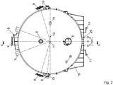
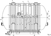
- the figures show a fluidized bed dryer arrangement.
- the arrangement is used to dry raw lignite.
- the fluidized bed dryer assembly comprises a container with a container shell 1 in a saddle bearing 18.
- the container is formed substantially cylindrical. At the end faces of the container is curved outward.
- the container is heated with a container heater 16, which has a condensate collector 17.
- the container is under a pressure of 4 bar.
- the container heater 16 is fed from a distributor 15 with heating steam.
- coal manholes 2 are provided in the upper part of the container.
- suitable locks such as a rotary valve, are provided which allow the introduction of coal in the standing under a pressure of 4 bar container.
- two vapor withdrawals 3 are arranged with a static separator 31. About the vapor exhausts 3 loaded with coal dust steam is discharged from the container interior.
- dry lignite is fed via the feed 4 into the dryer. Dry lignite, which has been filtered from the vapors by means of a vapor filter, is returned via a return 5 in the container interior.
- part of the pulverized coal is separated by a static separator 31, which then remains in the fluidized-bed dryer.
- a static separator 31 which then remains in the fluidized-bed dryer.
- a boarding door 6 is provided in the central region of the container shell. Laterally next to the access door 6, a sootblower 7 is provided for Schutulatgraphy during the Abfahrvones and the destruction of coal floes.
- the sootblower is a cleaning device which, during draining of the dryer, i. during the shutdown prevents dry carbon deposits on the Schundrohren.
- the sootblower 7 is operated with steam as a cleaning medium. At the same time, floe formation (coal lumps) occurring during operation due to targeted steam pulses can be destroyed on the fluidized bed surface.
- the rinsing device 30 is a rinsing nozzle, with which carbon deposits are eliminated on the dryer floor during emptying of the dryer.
- a nozzle bottom 28 is arranged. From the nozzles of the nozzle plate 28 exits pressurized steam. With this steam, a fluidized bed of coal is produced. Part of the fluidization steam can be introduced via side nozzles 32 in the upper region of the fluidized bed in order to support the turbulence and thus the interference of the moist raw carbon.
- the nozzles of the nozzle bottom are charged with different amounts of steam.
- a larger amount of steam exits the nozzles than in the middle region.
- too high steam quantities are uneconomical. It is therefore desirable to produce the fluidized bed with as little steam as possible.
- the raw coal has a high water content in the range of, for example, 50-60%. The surface moisture therefore leads to bonding. If the raw coal from the coal manholes 2 comes down, there is a risk of floe formation. A higher amount of steam from the nozzles of the nozzle bottom 28 below the coal manholes 2 increases the particle velocity and avoids the risk of floe formation. In the dryer zone in the middle area of the nozzle bottom, this high amount of steam is not required. There you can work with usual amounts of steam. In this way, it continues to work with a minimum of steam.
- a condensation heating surface 22 is arranged in the lower, central region of the container above the nozzle bottom.
- the Kondensationsterrorism composition 22 consists of a plurality of parallel heating tubes of equal length. It extends over the entire length of the substantially cylindrical part of the container.
- the heating pipes are held by a support 26.
- the longitudinal axis of the heating pipes runs from right to left in FIG. 4 parallel to the longitudinal axis of the container.
- cross section in FIG. 6 It can be seen that the heating pipes almost extend to the container wall zoom. As a result, the dead volume is kept low.
- the heating tubes of the condensation heating surface 22 are welded to a perforated plate 27.
- the perforated plate 27 is part of a partition wall between the fluidized bed and a laterally arranged antechamber. Together with the perforated plate 27 forms a hemispherical shell an inlet chamber 21. On the output side, the corresponding perforated plate with a hemispherical shell forms an outlet chamber 23.
- the inlet chamber 21 is connected via connecting tubes 20 with a heating steam inlet 9.
- the inlet chamber 21 has a condensate drain 25.
- the outlet chamber 23 has a condensate drain 24. Heating steam enters via the Schudampfeinberg 9 and the connecting pipes 20 in the inlet chamber 21 a. This forms a distributor.
- the heating steam passes through the holes in the perforated plate 27 in the welded thereto heating tubes the Kondensations2020 Structure 22.
- the Wiendampfkondensat passes through the holes of the perforated plate 27 in the outlet chamber 23. This forms a collector. Due to the condensate drain 24 occurs water, which is condensed in the fluidized bed in the heating tubes, again from.
- the coal entering through the coal manhole 2 enters the fluidized bed.
- the fluidized bed is heated and dried.
- the dry lignite is transported via a connection shaft 29 in the bottom of the container to a screw conveyor. There it is available for further use.
- the inlet and outlet chambers 21 and 23 can be hemispherical in shape.
- the monitoring of the arrangement is done with measuring instruments. These include thermocouples, which are arranged at temperature measuring points 11 and pressure gauge for measuring the pressure at pressure measuring points 12. A visual monitoring of the drying process via a sight glass 13 with flushing.
- the condensation heating surface 22 has a continuous, vertical lane 14 in the longitudinal direction of the container 1. There are no heating pipes in it.
- the vertical lane is directly below the coal manholes 2 in the center of the vessel. With the lane 14 improved mixing of the raw coal is achieved in the dry coal. The raw coal is better distributed and can not remain above the coal bed of the fluidized bed. The coal top edge is not too close above the condensation heating surface to avoid floe formation. A gap in the dry area leads to a good introduction of the raw coal.
Landscapes
- Engineering & Computer Science (AREA)
- Mechanical Engineering (AREA)
- General Engineering & Computer Science (AREA)
- Life Sciences & Earth Sciences (AREA)
- Microbiology (AREA)
- Chemical & Material Sciences (AREA)
- Combustion & Propulsion (AREA)
- Drying Of Solid Materials (AREA)
- Solid Fuels And Fuel-Associated Substances (AREA)
Applications Claiming Priority (1)
| Application Number | Priority Date | Filing Date | Title |
|---|---|---|---|
| DE102011001031A DE102011001031A1 (de) | 2011-03-02 | 2011-03-02 | Wirbelschicht-Trockneranordnung |
Publications (2)
| Publication Number | Publication Date |
|---|---|
| EP2495518A2 true EP2495518A2 (fr) | 2012-09-05 |
| EP2495518A3 EP2495518A3 (fr) | 2015-09-16 |
Family
ID=45655189
Family Applications (1)
| Application Number | Title | Priority Date | Filing Date |
|---|---|---|---|
| EP12152063.9A Withdrawn EP2495518A3 (fr) | 2011-03-02 | 2012-01-23 | Agencement de séchage par lit fluidisé |
Country Status (2)
| Country | Link |
|---|---|
| EP (1) | EP2495518A3 (fr) |
| DE (1) | DE102011001031A1 (fr) |
Citations (4)
| Publication number | Priority date | Publication date | Assignee | Title |
|---|---|---|---|---|
| US2629938A (en) * | 1949-03-03 | 1953-03-03 | Kaiser Aluminium Chem Corp | Method and apparatus for treating solids |
| US3605275A (en) * | 1968-07-29 | 1971-09-20 | Struthers Wells Corp | Fluidized bed dryer |
| DE19620047C2 (de) | 1996-05-18 | 2002-06-27 | Rwe Rheinbraun Ag | Verfahren und Vorrichtung zum Trocknen von Braunkohle |
| US20110247232A1 (en) * | 2009-10-08 | 2011-10-13 | The Korea Institute Of Energy Research | Fluidized bed drying apparatus |
Family Cites Families (3)
| Publication number | Priority date | Publication date | Assignee | Title |
|---|---|---|---|---|
| DE10251233A1 (de) * | 2002-11-02 | 2004-05-13 | Matthias Limburg | Arbeitsmaschine zur Zerkleinerung von Brennstoffen, zur Trocknung von Brennstoffen und zur Zuführung von Brennstoffen in Brennräume |
| US8523963B2 (en) * | 2004-10-12 | 2013-09-03 | Great River Energy | Apparatus for heat treatment of particulate materials |
| CN102177406B (zh) * | 2008-08-12 | 2013-11-06 | 施维英生物泥公司 | 闭环干燥系统和方法 |
-
2011
- 2011-03-02 DE DE102011001031A patent/DE102011001031A1/de not_active Withdrawn
-
2012
- 2012-01-23 EP EP12152063.9A patent/EP2495518A3/fr not_active Withdrawn
Patent Citations (4)
| Publication number | Priority date | Publication date | Assignee | Title |
|---|---|---|---|---|
| US2629938A (en) * | 1949-03-03 | 1953-03-03 | Kaiser Aluminium Chem Corp | Method and apparatus for treating solids |
| US3605275A (en) * | 1968-07-29 | 1971-09-20 | Struthers Wells Corp | Fluidized bed dryer |
| DE19620047C2 (de) | 1996-05-18 | 2002-06-27 | Rwe Rheinbraun Ag | Verfahren und Vorrichtung zum Trocknen von Braunkohle |
| US20110247232A1 (en) * | 2009-10-08 | 2011-10-13 | The Korea Institute Of Energy Research | Fluidized bed drying apparatus |
Also Published As
| Publication number | Publication date |
|---|---|
| DE102011001031A1 (de) | 2012-09-06 |
| EP2495518A3 (fr) | 2015-09-16 |
Similar Documents
| Publication | Publication Date | Title |
|---|---|---|
| DE69728984T2 (de) | Verfahren und vorrichtung zum auftragen eines materials auf ein bahnförmiges substrat | |
| DE3248384C2 (de) | Einrichtung zur Entwässerung von Feststoffen | |
| DE102006009442A1 (de) | Kompressionsschraube mit einer Kombination aus einzelnen und doppelten Gewindegängen | |
| WO1997046304A1 (fr) | Procede et dispositif de sechage de gaz, notamment de gaz naturel | |
| DE60217183T2 (de) | Vorrichtung zum trocknen eines teilchenförmigen produkts mit überhitztem dampf | |
| DE19620047C2 (de) | Verfahren und Vorrichtung zum Trocknen von Braunkohle | |
| DE1511217B1 (de) | Trockenzylinder fuer Papiermaschinen | |
| DE69002947T2 (de) | Verfahren zur erniedrigung des ölgehalts einer bohrflüssigkeit und apparat zur anwendung dieses verfahrens. | |
| EP2495518A2 (fr) | Agencement de séchage par lit fluidisé | |
| DE3137503A1 (de) | Entspannungs-verdampfer fuer geothermische kraftwerke | |
| AT516780A2 (de) | Vorrichtung zum Vorheizen eines zu dispergierenden Recycling-Faserstoffes | |
| DE9114967U1 (de) | Verdampfereinrichtung zur Behandlung von Schlämmen | |
| EP2498034A2 (fr) | Agencement de séchage par lit fluidisé | |
| EP2352959B1 (fr) | Sechoir en lit fluidise a chauffage indirect | |
| DE3107259A1 (de) | "verfahren und vorrichtung zum abscheiden von dampf aus holzfaserstoff enthaltendem material" | |
| EP2495495A2 (fr) | Agencement de séchage par lit fluidisé | |
| DE1619942A1 (de) | Verfahren und Vorrichtung zum Entgasen von fluessigen Suspensionen | |
| DE102013100595A1 (de) | System zum Trocknen von Schlamm | |
| AT504589B1 (de) | Verfahren und vorrichtung zur entfernung von gas aus holzschnitzeln | |
| EP4136290A1 (fr) | Caisson de soufflage de vapeur comprenant un conditionnement de vapeur | |
| EP2395306A2 (fr) | Procédé et dispositif de séchage de fibres, notamment de copeaux de bois | |
| DD271944B5 (de) | Indirekt beheizte dampfwirbelschichttrocknungsanlage | |
| DE202019106564U1 (de) | Staubabscheider und Verdampfungstrockner | |
| DE2512162C3 (de) | Verfahren und Vorrichtung zum Schnelltrocknen von Cellulosepulpe | |
| AT508526B1 (de) | Vorrichtung und verfahren zum zuführen von faserpulpe zu einem bahnbildungsträger |
Legal Events
| Date | Code | Title | Description |
|---|---|---|---|
| PUAI | Public reference made under article 153(3) epc to a published international application that has entered the european phase |
Free format text: ORIGINAL CODE: 0009012 |
|
| AK | Designated contracting states |
Kind code of ref document: A2 Designated state(s): AL AT BE BG CH CY CZ DE DK EE ES FI FR GB GR HR HU IE IS IT LI LT LU LV MC MK MT NL NO PL PT RO RS SE SI SK SM TR |
|
| AX | Request for extension of the european patent |
Extension state: BA ME |
|
| 17P | Request for examination filed |
Effective date: 20130304 |
|
| RAP1 | Party data changed (applicant data changed or rights of an application transferred) |
Owner name: BABCOCK BORSIG STEINMUELLER GMBH |
|
| PUAL | Search report despatched |
Free format text: ORIGINAL CODE: 0009013 |
|
| AK | Designated contracting states |
Kind code of ref document: A3 Designated state(s): AL AT BE BG CH CY CZ DE DK EE ES FI FR GB GR HR HU IE IS IT LI LT LU LV MC MK MT NL NO PL PT RO RS SE SI SK SM TR |
|
| AX | Request for extension of the european patent |
Extension state: BA ME |
|
| RIC1 | Information provided on ipc code assigned before grant |
Ipc: F23K 1/04 20060101ALI20150813BHEP Ipc: F26B 3/084 20060101AFI20150813BHEP |
|
| STAA | Information on the status of an ep patent application or granted ep patent |
Free format text: STATUS: EXAMINATION IS IN PROGRESS |
|
| 17Q | First examination report despatched |
Effective date: 20180425 |
|
| STAA | Information on the status of an ep patent application or granted ep patent |
Free format text: STATUS: THE APPLICATION IS DEEMED TO BE WITHDRAWN |
|
| 18D | Application deemed to be withdrawn |
Effective date: 20190801 |