EP2495562A2 - Zweidimensionale virtuelle array-sonde für dreidimensionale ultraschallbildgebung - Google Patents
Zweidimensionale virtuelle array-sonde für dreidimensionale ultraschallbildgebung Download PDFInfo
- Publication number
- EP2495562A2 EP2495562A2 EP10826987A EP10826987A EP2495562A2 EP 2495562 A2 EP2495562 A2 EP 2495562A2 EP 10826987 A EP10826987 A EP 10826987A EP 10826987 A EP10826987 A EP 10826987A EP 2495562 A2 EP2495562 A2 EP 2495562A2
- Authority
- EP
- European Patent Office
- Prior art keywords
- ultrasonic
- wave
- probe
- dimensional
- guides
- Prior art date
- Legal status (The legal status is an assumption and is not a legal conclusion. Google has not performed a legal analysis and makes no representation as to the accuracy of the status listed.)
- Withdrawn
Links
- 239000000523 sample Substances 0.000 title claims abstract description 48
- 238000003384 imaging method Methods 0.000 title claims abstract description 8
- 239000000463 material Substances 0.000 claims description 3
- XAGFODPZIPBFFR-UHFFFAOYSA-N aluminium Chemical compound [Al] XAGFODPZIPBFFR-UHFFFAOYSA-N 0.000 claims description 2
- 229910052782 aluminium Inorganic materials 0.000 claims description 2
- 238000000034 method Methods 0.000 description 8
- 230000001066 destructive effect Effects 0.000 description 7
- 238000007689 inspection Methods 0.000 description 7
- 230000004913 activation Effects 0.000 description 2
- 230000007547 defect Effects 0.000 description 2
- 238000003745 diagnosis Methods 0.000 description 2
- 230000000694 effects Effects 0.000 description 2
- 230000001788 irregular Effects 0.000 description 2
- 238000003491 array Methods 0.000 description 1
- 230000000739 chaotic effect Effects 0.000 description 1
- 238000002474 experimental method Methods 0.000 description 1
- 230000007274 generation of a signal involved in cell-cell signaling Effects 0.000 description 1
- 230000002250 progressing effect Effects 0.000 description 1
- 238000011160 research Methods 0.000 description 1
Images


Classifications
-
- G—PHYSICS
- G01—MEASURING; TESTING
- G01N—INVESTIGATING OR ANALYSING MATERIALS BY DETERMINING THEIR CHEMICAL OR PHYSICAL PROPERTIES
- G01N29/00—Investigating or analysing materials by the use of ultrasonic, sonic or infrasonic waves; Visualisation of the interior of objects by transmitting ultrasonic or sonic waves through the object
- G01N29/22—Details, e.g. general constructional or apparatus details
- G01N29/24—Probes
- G01N29/2437—Piezoelectric probes
-
- G—PHYSICS
- G01—MEASURING; TESTING
- G01Q—SCANNING-PROBE TECHNIQUES OR APPARATUS; APPLICATIONS OF SCANNING-PROBE TECHNIQUES, e.g. SCANNING PROBE MICROSCOPY [SPM]
- G01Q70/00—General aspects of SPM probes, their manufacture or their related instrumentation, insofar as they are not specially adapted to a single SPM technique covered by group G01Q60/00
- G01Q70/08—Probe characteristics
-
- G—PHYSICS
- G01—MEASURING; TESTING
- G01N—INVESTIGATING OR ANALYSING MATERIALS BY DETERMINING THEIR CHEMICAL OR PHYSICAL PROPERTIES
- G01N2291/00—Indexing codes associated with group G01N29/00
- G01N2291/10—Number of transducers
- G01N2291/106—Number of transducers one or more transducer arrays
Definitions
- the present invention relates to development of an ultrasonic probe, which is used for ultrasonic image diagnosis and non-destructive inspection, and more particularly, to a 2-dimensional virtual array probe for real-time 3-dimensioanl ultrasonic imaging.
- a widely used 2-dimension array probe includes piezoelectric elements as many as thousands, forms an array by fixedly arranging ultrasonic transducers at regular intervals, which are capable of transmitting/receiving ultra-sonic waves, and detects a defect in an object to be inspected by using a pulse-echo method.
- a 60x60 array probe may be exemplified.
- total 3600 ultrasonic transducers are needed and the respective 3600 ultrasonic transducers are controlled using the respective 3600 channels to obtain a 3-dimensional image.
- the ultrasonic transducers since the ultrasonic transducers have to be provided for each channel, there is a problem of highly costing for configuring a system.
- a paper ( G. montaldo. D. Palacio, M. Tanter, M. Fink, IEEE Trans. Ultrson., Ferroelect., Freq. Contr: 52(2005), 1489-1497 ) discloses a method of configuring ultrasonic non-destructive apparatus which can obtain a similar effect and reduce the number of the transducers as compared with the related art.
- the method disclosed in the paper has a problem that a plurality of transducers are also used and ultrasonic beam is rapidly spread after being focused at a focal point due to a characteristic of a time inversion method of the related art. That is, since the ultrasonic wave generated from the transducer is not transmitted in parallel to the object to be inspected and has a property of instantly spreading after being focused at the focal point, there is a problem having a difficulty in implementing the pulse-echo type non-destructive inspection using such a sound beam.
- the present invention have been made in view of the above problems, and unlike a 2-dimensional array probe including thousands of the piezoelectric-elements in the related art, provide a 2-dimensional virtual array probe for 3-dimensional ultrasonic imaging, of which structure is improved to generate an irregular internal reflection.
- the 2-dimensional virtual array probe for 3-dimensional ultrasonic imaging includes: an ultrasonic transducer; a metallic probe body including an ultrasonic wave emission surface in which a plurality of wave-guides are arranged in 2-dimensional array and a 1/8 sphere-shaped recess for irregularly reflecting ultrasonic wave emitted from the ultrasonic transducer in an inside thereof; a piezoelectric sheet arranged on the ultrasonic wave emission surface to make contact with an object to be inspected and configured to pass the ultrasonic waves emitted from the probe toward the object to be inspected and output a signal by detecting the ultrasonic waves reflected from the object to be detected; and a control unit configured to control the ultrasonic transducer so that the plurality of wave-guides sequentially generate ultrasonic wave.
- the probe body may include an aluminum material.
- each probe may have a same cross-sectional area and height as one side surface of the probe body is processed.
- a radius of the recess may have a size of 30-40% of the height of the probe body.
- the ultrasonic transducer may be installed in any surface other than the ultrasonic wave emission surface of the probe body.
- the present invention it is possible to provide inspection equipment which has a performance similar to the non-destructive inspection apparatus using the plurality of ultrasonic waves, with only one ultrasonic transducer, thereby reducing a unit price of the non-destructive inspection apparatus.
- FIG. 1 is a view illustrating a configuration of a probe of a non-destructive inspection apparatus according to the present invention.
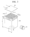
- FIG. 2 is an exploded perspective view of FIG. 1 .
- FIG. 3 is a graph of a signal received at an end of a wave-guide prior to time inversion.
- FIG.4 is a graph of a signal in which the signal of FIG. 3 is time-inverted.
- FIGS. 5 and 6 are graphs showing pulse signals focused on a time axis, which are generated through ultrasonic transducer using software.
- FIG. 7 is a graph showing an example of a pulse-echo signal converted into a distance.
- a 2-dimensional virtual array probe for 3-dimensional ultrasonic imaging includes an ultrasonic transducer 100, a probe body 200, a piezoelectric sheet 300, and a control unit 400.
- the ultrasonic transducer 100 corresponds to a signal generation unit and receives a pulse signal corresponding to 5Mhz to generate an ultrasonic signal using a signal generator and a power amplifier, which are not shown in drawing. At this time, an amplitude of the generated pulse signal is changed depending on a location of a wave-guide, in which a ultrasonic wave is to be generated, and is obtained experimentally.
- the probe body 200 is provided in a hexahedral shape having a square-shaped cross-sectional area.
- a plurality of wave-guides 210 is formed in one side surface of the probe body 200 and the probe body 200 includes a recess 220 for irregularly reflecting the ultrasonic waves received from the ultrasonic transducer 100.
- the wave-guide 210 has been configured to form total 100 channels (210-1 ⁇ 210-100) with a 10x10 array, the present invention is not limited thereto and according to the user's need, the wave-guide 210 may be configured with different arrays, for example, total 400 channels with a 20x20 array, or total 3600 channels with a 60x60 array.
- the wave-guide 210 forms scan lines to transmit the ultrasonic waves.
- One surface of the probe body 200 is formed using a machine tool such as lathes so that the wave-guides 210 have the same cross-sectional area A and height h.
- the object to be inspected is located on a top surface of the wave-guides 210.
- the recess 220 is formed to have a 1/8 sphere shape and when assuming that the height of the probe body 200 is H, it is preferable that the radius r of the sphere have about 20 ⁇ 30% value of the height H.
- the recess 220 be formed in at least 3 surfaces of the probe body 200. According to this configuration, the ultrasonic wave generated from the ultrasonic transducer 100 has a chaotic motion in the probe body 200, thereby transmitting the ultrasonic signal through only one of the plurality of wave-guides 210 selected by the user.
- the piezoelectric sheet 300 is attached to the surface in which the wave-guides are formed of the probe body 200 and the object to be inspected is placed thereon.
- the piezoelectric sheet 300 transmits the ultrasonic wave and detects a reflective signal reflected from the object to be inspected.
- the control unit 400 includes an RF amplifier connected to the ultrasonic transducer 100 and the piezoelectric sheet 300 to drive/control the ultrasonic transducer 100, a signal generator, and a signal processor, which collects reflective signal information according to ultrasonic scan lines formed for the plurality of the wave-guides 210 and analyzes the reflective signal information, and the like. The operations of the control unit 400 will be described in detail.
- the user changes a frequency of about 5MHz band by using the RF amplifier and the signal generator provided in the control unit 400 to vibrate the end of any one 210-1of the wave-guides as shown in FIG. 3 , and makes a signal as shown in FIG. 4 by time inversion of the signal of FIG. 3 .
- the signal made by this method is supplied to the signal generator and power amplifier to allow the ultrasonic transducer 100 to generate the ultrasonic wave.
- the sound beam signal output from the corresponding wave-guide 210-1 has a pulse form focused on the time axis as shown in FIGS. 5 and 6 , it is possible to secure resolution according to a progressing direction.
- the respective wave-guides 210-1 ⁇ 210-n generate ultrasonic waves to form scanning channels.
- the 1/8 sphere-shaped recess 220 is formed in the probe body 200. That is, the ultrasonic wave generated from the ultrasonic transducer 100 has an irregular motion in the probe body 200, due to a shape of the recess 220. Accordingly, when appropriately adjusting the waveform of the ultrasonic wave generated from the transducer 100 using a principal of time inversion, it is possible to deliver the ultrasonic wave generated from the ultrasonic transducer 100 through only one of the plurality of the wave-guides 210, which are formed in the one surface of the probe body 200. Accordingly, if it is possible to calculate an appropriate waveform through an experiment, which can vibrate the respective wave-guides 210-1 ⁇ 210-n, an independent scanning channel can be formed using the waveform value.
- control unit 400 may scan the object to be inspected placed on the wave-guides 210 according to channels, while changing the waveform in a regular cycle.
- the piezoelectric sheet 300 is arranged between the wave-guides 210 and the object to be inspected to allow the ultrasonic signal generated from the wave-guides 210 to be transmitted and the ultrasonic signal reflected from the object to be inspected to be detected.
- a signal detected during activation of the first channel is confirmed as a reflective signal of the first channel; and when another ultrasonic wave is generated through a second wave-guide 210-2, another signal detected during activation of the second channel is confirmed as another reflective signal of the second channel. It is possible to detect scanning signals of all channels with the same method, thereby obtaining a 3-dimensional diagnosis image of the object to be inspected.
Landscapes
- General Health & Medical Sciences (AREA)
- Health & Medical Sciences (AREA)
- General Physics & Mathematics (AREA)
- Physics & Mathematics (AREA)
- Chemical & Material Sciences (AREA)
- Biochemistry (AREA)
- Analytical Chemistry (AREA)
- Life Sciences & Earth Sciences (AREA)
- Immunology (AREA)
- Pathology (AREA)
- Nuclear Medicine, Radiotherapy & Molecular Imaging (AREA)
- Radiology & Medical Imaging (AREA)
- Investigating Or Analyzing Materials By The Use Of Ultrasonic Waves (AREA)
- Transducers For Ultrasonic Waves (AREA)
- Ultra Sonic Daignosis Equipment (AREA)
Applications Claiming Priority (2)
| Application Number | Priority Date | Filing Date | Title |
|---|---|---|---|
| KR1020090103036A KR100970948B1 (ko) | 2009-10-28 | 2009-10-28 | 3차원 초음파 이미징을 위한 2차원 가상 배열형 탐촉자 |
| PCT/KR2010/006814 WO2011052902A2 (ko) | 2009-10-28 | 2010-10-06 | 3차원 초음파 이미징을 위한 2차원 가상 배열형 탐촉자 |
Publications (1)
| Publication Number | Publication Date |
|---|---|
| EP2495562A2 true EP2495562A2 (de) | 2012-09-05 |
Family
ID=42759167
Family Applications (1)
| Application Number | Title | Priority Date | Filing Date |
|---|---|---|---|
| EP10826987A Withdrawn EP2495562A2 (de) | 2009-10-28 | 2010-10-06 | Zweidimensionale virtuelle array-sonde für dreidimensionale ultraschallbildgebung |
Country Status (5)
| Country | Link |
|---|---|
| US (1) | US20120210795A1 (de) |
| EP (1) | EP2495562A2 (de) |
| JP (1) | JP2013509777A (de) |
| KR (1) | KR100970948B1 (de) |
| WO (1) | WO2011052902A2 (de) |
Families Citing this family (4)
| Publication number | Priority date | Publication date | Assignee | Title |
|---|---|---|---|---|
| KR101651424B1 (ko) * | 2013-03-29 | 2016-09-05 | 경일대학교산학협력단 | 비파괴 검사를 위한 장치 및 방법 |
| US9513327B2 (en) * | 2014-07-21 | 2016-12-06 | Acertara Acoustic Laboratories Llc | Testing of ultrasonic imaging systems |
| CN111929365B (zh) * | 2020-08-07 | 2023-08-22 | 广东汕头超声电子股份有限公司 | 一种超声成像检测显示方法 |
| CN116840355B (zh) * | 2023-07-05 | 2025-07-01 | 艾因蒂克科技(上海)有限公司 | 一种超声面阵探头、传感器以及探伤设备 |
Family Cites Families (10)
| Publication number | Priority date | Publication date | Assignee | Title |
|---|---|---|---|---|
| US3903498A (en) * | 1974-02-28 | 1975-09-02 | Us Health | Ultrasound imaging system utilizing shaped acoustic matching elements to increase the effective aperture of an acoustic transducer |
| US5434827A (en) * | 1993-06-15 | 1995-07-18 | Hewlett-Packard Company | Matching layer for front acoustic impedance matching of clinical ultrasonic tranducers |
| JP3288815B2 (ja) * | 1993-06-30 | 2002-06-04 | 株式会社東芝 | 2次元アレイ超音波プローブ |
| US6640634B2 (en) * | 2000-03-31 | 2003-11-04 | Kabushiki Kaisha Toshiba | Ultrasonic probe, method of manufacturing the same and ultrasonic diagnosis apparatus |
| JP2004364074A (ja) | 2003-06-06 | 2004-12-24 | Aloka Co Ltd | 超音波探触子および超音波探触子製造方法 |
| JP4503347B2 (ja) * | 2004-04-28 | 2010-07-14 | 日本電波工業株式会社 | 超音波探触子の製造方法 |
| JP4564286B2 (ja) * | 2004-06-14 | 2010-10-20 | 株式会社東芝 | 3次元超音波画像化装置 |
| JP4253334B2 (ja) | 2006-07-12 | 2009-04-08 | 株式会社東芝 | 2次元アレイ型超音波プローブ |
| JP2008086362A (ja) * | 2006-09-29 | 2008-04-17 | Fujifilm Corp | 超音波用探触子、超音波内視鏡、及び、超音波診断装置 |
| JP5038865B2 (ja) * | 2007-11-22 | 2012-10-03 | 株式会社東芝 | 超音波探触子、超音波診断装置、及び超音波探触子の製造方法 |
-
2009
- 2009-10-28 KR KR1020090103036A patent/KR100970948B1/ko active Active
-
2010
- 2010-10-06 EP EP10826987A patent/EP2495562A2/de not_active Withdrawn
- 2010-10-06 WO PCT/KR2010/006814 patent/WO2011052902A2/ko not_active Ceased
- 2010-10-06 JP JP2012536648A patent/JP2013509777A/ja active Pending
-
2012
- 2012-04-27 US US13/458,429 patent/US20120210795A1/en not_active Abandoned
Non-Patent Citations (1)
| Title |
|---|
| See references of WO2011052902A2 * |
Also Published As
| Publication number | Publication date |
|---|---|
| WO2011052902A2 (ko) | 2011-05-05 |
| WO2011052902A4 (ko) | 2011-11-17 |
| US20120210795A1 (en) | 2012-08-23 |
| JP2013509777A (ja) | 2013-03-14 |
| WO2011052902A3 (ko) | 2011-10-06 |
| KR100970948B1 (ko) | 2010-08-03 |
Similar Documents
| Publication | Publication Date | Title |
|---|---|---|
| CN108169331B (zh) | 薄板栅格翼结构焊缝相控阵超声检测装置及检测方法 | |
| JP5575554B2 (ja) | 超音波診断装置 | |
| JP3862793B2 (ja) | 超音波探触子及びそれを用いた超音波診断装置 | |
| EP2759817B1 (de) | Ultraschallholographieabbildungssystem und Verfahren | |
| CN100340867C (zh) | 便携式三维超声系统 | |
| CN103026257B (zh) | 使用剪切波成像的方法和装置 | |
| US6923066B2 (en) | Ultrasonic transmitting and receiving apparatus | |
| US8286467B2 (en) | Method for imaging surface roughness using acoustic emissions induced by ultrasound | |
| CN110367943A (zh) | 相控阵超声换能器和超声相控检测系统 | |
| US20120250454A1 (en) | Method and system for shaping a cmut membrane | |
| CN103505243A (zh) | 测量超声波的声吸收或衰减 | |
| JP4542814B2 (ja) | 超音波検査方法 | |
| CN109212037A (zh) | 一种空气耦合超声相控阵检测装置 | |
| CN102688066A (zh) | 超声波诊断装置和产生超声波图像方法 | |
| CN102641135A (zh) | 超声波探测器和超声波诊断装置 | |
| EP2495562A2 (de) | Zweidimensionale virtuelle array-sonde für dreidimensionale ultraschallbildgebung | |
| WO2020084116A1 (en) | Ultrasound scanning apparatus for scanning non-planar surfaces | |
| EP3592240B1 (de) | System zur ortung eines akustischen sensors | |
| JP2002336246A (ja) | 超音波撮像方法及び超音波撮像装置 | |
| CN102688065A (zh) | 超声波诊断装置和超声波图像产生方法 | |
| CN102648861A (zh) | 超声波探测器和超声波诊断装置 | |
| JP2013215384A (ja) | 超音波診断装置および超音波画像生成方法 | |
| CN102670244A (zh) | 超声波诊断装置和超声波图像产生方法 | |
| JP6116239B2 (ja) | 被検体情報取得装置および被検体情報取得方法 | |
| Stepinski et al. | Designing 2D arrays for SHM of planar structures: a review |
Legal Events
| Date | Code | Title | Description |
|---|---|---|---|
| PUAI | Public reference made under article 153(3) epc to a published international application that has entered the european phase |
Free format text: ORIGINAL CODE: 0009012 |
|
| 17P | Request for examination filed |
Effective date: 20120517 |
|
| AK | Designated contracting states |
Kind code of ref document: A2 Designated state(s): AL AT BE BG CH CY CZ DE DK EE ES FI FR GB GR HR HU IE IS IT LI LT LU LV MC MK MT NL NO PL PT RO RS SE SI SK SM TR |
|
| DAX | Request for extension of the european patent (deleted) | ||
| STAA | Information on the status of an ep patent application or granted ep patent |
Free format text: STATUS: THE APPLICATION IS DEEMED TO BE WITHDRAWN |
|
| 18D | Application deemed to be withdrawn |
Effective date: 20140501 |