EP2495840A2 - Appareil de conversion de puissance - Google Patents
Appareil de conversion de puissance Download PDFInfo
- Publication number
- EP2495840A2 EP2495840A2 EP12154212A EP12154212A EP2495840A2 EP 2495840 A2 EP2495840 A2 EP 2495840A2 EP 12154212 A EP12154212 A EP 12154212A EP 12154212 A EP12154212 A EP 12154212A EP 2495840 A2 EP2495840 A2 EP 2495840A2
- Authority
- EP
- European Patent Office
- Prior art keywords
- output
- control unit
- current
- voltage
- input
- Prior art date
- Legal status (The legal status is an assumption and is not a legal conclusion. Google has not performed a legal analysis and makes no representation as to the accuracy of the status listed.)
- Withdrawn
Links
Images


Classifications
-
- G—PHYSICS
- G05—CONTROLLING; REGULATING
- G05F—SYSTEMS FOR REGULATING ELECTRIC OR MAGNETIC VARIABLES
- G05F1/00—Automatic systems in which deviations of an electric quantity from one or more predetermined values are detected at the output of the system and fed back to a device within the system to restore the detected quantity to its predetermined value or values, i.e. retroactive systems
- G05F1/66—Regulating electric power
- G05F1/67—Regulating electric power to the maximum power available from a generator, e.g. from solar cell
-
- H—ELECTRICITY
- H02—GENERATION; CONVERSION OR DISTRIBUTION OF ELECTRIC POWER
- H02J—ELECTRIC POWER NETWORKS; CIRCUIT ARRANGEMENTS OR SYSTEMS FOR SUPPLYING OR DISTRIBUTING ELECTRIC POWER; SYSTEMS FOR STORING ELECTRIC ENERGY
- H02J3/00—Circuit arrangements for AC mains or AC distribution networks
- H02J3/38—Arrangements for feeding a single network from two or more generators or sources in parallel; Arrangements for feeding already energised networks from additional generators or sources in parallel
- H02J3/381—Dispersed generators
-
- H—ELECTRICITY
- H02—GENERATION; CONVERSION OR DISTRIBUTION OF ELECTRIC POWER
- H02J—ELECTRIC POWER NETWORKS; CIRCUIT ARRANGEMENTS OR SYSTEMS FOR SUPPLYING OR DISTRIBUTING ELECTRIC POWER; SYSTEMS FOR STORING ELECTRIC ENERGY
- H02J3/00—Circuit arrangements for AC mains or AC distribution networks
- H02J3/38—Arrangements for feeding a single network from two or more generators or sources in parallel; Arrangements for feeding already energised networks from additional generators or sources in parallel
- H02J3/46—Controlling the sharing of generated power between the generators, sources or networks
-
- H—ELECTRICITY
- H02—GENERATION; CONVERSION OR DISTRIBUTION OF ELECTRIC POWER
- H02J—ELECTRIC POWER NETWORKS; CIRCUIT ARRANGEMENTS OR SYSTEMS FOR SUPPLYING OR DISTRIBUTING ELECTRIC POWER; SYSTEMS FOR STORING ELECTRIC ENERGY
- H02J2101/00—Supply or distribution of decentralised, dispersed or local electric power generation
- H02J2101/20—Dispersed power generation using renewable energy sources
- H02J2101/22—Solar energy
- H02J2101/24—Photovoltaics
- H02J2101/25—Photovoltaics involving maximum power point tracking control for photovoltaic sources
-
- H—ELECTRICITY
- H02—GENERATION; CONVERSION OR DISTRIBUTION OF ELECTRIC POWER
- H02M—APPARATUS FOR CONVERSION BETWEEN AC AND AC, BETWEEN AC AND DC, OR BETWEEN DC AND DC, AND FOR USE WITH MAINS OR SIMILAR POWER SUPPLY SYSTEMS; CONVERSION OF DC OR AC INPUT POWER INTO SURGE OUTPUT POWER; CONTROL OR REGULATION THEREOF
- H02M1/00—Details of apparatus for conversion
- H02M1/0067—Converter structures employing plural converter units, other than for parallel operation of the units on a single load
- H02M1/007—Plural converter units in cascade
-
- Y—GENERAL TAGGING OF NEW TECHNOLOGICAL DEVELOPMENTS; GENERAL TAGGING OF CROSS-SECTIONAL TECHNOLOGIES SPANNING OVER SEVERAL SECTIONS OF THE IPC; TECHNICAL SUBJECTS COVERED BY FORMER USPC CROSS-REFERENCE ART COLLECTIONS [XRACs] AND DIGESTS
- Y02—TECHNOLOGIES OR APPLICATIONS FOR MITIGATION OR ADAPTATION AGAINST CLIMATE CHANGE
- Y02E—REDUCTION OF GREENHOUSE GAS [GHG] EMISSIONS, RELATED TO ENERGY GENERATION, TRANSMISSION OR DISTRIBUTION
- Y02E10/00—Energy generation through renewable energy sources
- Y02E10/50—Photovoltaic [PV] energy
- Y02E10/56—Power conversion systems, e.g. maximum power point trackers
Definitions
- FIG. 2 shows a structural example of the power conversion apparatus PCS.
- the power conversion apparatus PCS comprises a DC-DC converter (a chopper) unit 10 to which the direct-current power is supplied and a DC-AC converter unit 20 which converts the direct-current power into alternating-current power and outputs the converted power.
- DC-DC converter a chopper
- the DC-DC converter unit 10 is a boost converter that boosts and outputs a direct-current input voltage from the dispersed power source in order to perform power conversion while being interconnected with an electric power system.
- the DC-AC inverter unit 20 converts the direct-current input voltage and a direct-current input current into three-phase voltage and current and outputs the converted voltage and current.
- the DC-DC converter unit 10 includes a first input terminal 12 electrically connected to positive output terminals of the photovoltaic arrays PV_1 to PV_N, a second input terminal 14 electrically connected to negative output terminals, a first output terminal 16 electrically connected to the first input terminal 12, a second output terminal 18 electrically connected to the second input terminal 14, a coil connected between the first input terminal 12 and the first output terminal 16 in series, a diode connected in a forward direction from an output end of the coil to the first output terminal 16, a switch that changes over connection achieved between the second input terminal 14 and the output end of the coil, a capacitor connected between the first output terminal 16 and the second output terminal 18, and a controller which outputs a signal for controlling ON and OFF of the switch.
- a wiring line between the second input terminal 14 and the second output terminal 18 is connected to an input end of the diode D_chop (an output end of the choke coil L_chop) and a switch Sw_chop, and it is further connected to an output end of the diode D_chop through a capacitor C_link.
- the second output terminal 18 is electrically connected to a fourth input terminal 24 of the DC_AC inverter unit 20.
- the switch Sw_chop includes a source terminal, a drain terminal, and a drain terminal, and connection between the source terminal and the drain terminal is controlled by a signal applied to the drain terminal.
- the DC-DC converter unit 10 includes a controller which outputs a PWM signal for controlling a gate terminal potential in the switch Sw_chop.
- energy is stored in the choke coil L_chop by currents flowing in from the photovoltaic arrays PV_1 to PV_N when a source electrode and a drain electrode of the switch Sw_chop are electrically conductive (ON), and the energy stored in the choke coil L_chop is discharged and added to voltages input from the photovoltaic arrays PV_1 to PV_N to be output to the DC-AC inverter unit 20 when the source electrode and the drain electrode of the switch Sw_chop are not electrically conductive (OFF).
- the DC-AC inverter unit 20 includes two input terminals 22 and 24 and three output terminals 26, 27, and 28.
- a switch Sw1 is interposed between the third input terminal 22 and the third output terminal 26.
- a switch Sw3 is interposed between the third input terminal 22 and the fourth output terminal 27.
- a switch Sw5 is interposed between the third input terminal 22 and the fifth output terminal 28.
- a switch Sw2 is interposed between the fourth input terminal 24 and the third output terminal 26.
- a switch Sw4 is interposed between the fourth input terminal 24 and the fourth output terminal 27.
- a switch Sw6 is interposed between the fourth input terminal 24 and the fifth output terminal 28.
- FIG. 3 shows an example of a control block of a controller which controls a gate terminal potential of the switch Sw_chop in the DC-DC converter unit 10.
- the control block depicted in FIG. 3 comprises an MPPT control unit 32 which receives a direct-current voltage (a converter input voltage Vconv-k1 ⁇ Iconv) and a converter input current Iconv, a control unit CTRL including a voltage control unit (AVR: Automatic Voltage Regulator) 34 which performs PI control and a current control unit (ACR: Automatic Current Regulator) 36 which performs PI control, and a PWM comparator 38.
- AVR Automatic Voltage Regulator
- ACR Automatic Current Regulator
- An MPPT timing signal MPPT_sync is input to the MPPT control unit 32 to synchronize an operation of the MPPT control. It is to be noted that the converter input voltage Vconv is an output voltage from each of the photovoltaic arrays PV_1 to PV_N, and the converter input current Iconv is an output current from each of the photovoltaic arrays PV_1 to PV_N.
- FIG. 4 is a flowchart for explaining an example of the MPPT control which is called a hill-climbing method.
- the hill-climbing method is a method generally used in a photovoltaic system which is a dispersed power source, and it is a method of searching for a reference voltage so that output power from a photovoltaic array becomes maximum with an open voltage being determined as an initial value.
- step ST2 whether the direct-current power error ⁇ P is zero is judged (a step ST2), and it is determined that the voltage does not fluctuate when the direct-current power error ⁇ P is zero.
- step ST3 whether the direct-current power error ⁇ P is larger than zero is judged (a step ST3).
- step ST4 When the direct-current error ⁇ P is larger than zero, whether the direct-current voltage error ⁇ V is larger than zero is further judged (a step ST4). When the direct-current voltage error ⁇ V is larger than zero, the voltage is increased. When the direct-current voltage error ⁇ V is not larger than zero, the voltage is decreased.
- step ST5 When the direct-current power error ⁇ P is not larger than zero at the step ST3, whether the direct-current voltage error ⁇ V is larger than zero is further judged (a step ST5). When the direct-current voltage error ⁇ V is larger than zero, the voltage is decreased. When the direct-current voltage error ⁇ V is not larger than zero, the voltage is increased.
- the MPPT control unit 32 senses the converter input voltage Vconv and the converter input current Iconv, outputs the direct-current voltage error ⁇ V and the direct-current power error ⁇ P for each MPPT period, increases or decreases the reference voltage or determines no fluctuation of the reference voltage depending on magnitudes of these output errors, and outputs a reference voltage Vconv* based on a judgment result.
- FIG. 5 is a view for explaining an example of an MPPT timing signal MPPT_sync serving as a reference of the MPPT period during which the MPPT control is performed.
- a system voltage of the electric power system is detected, and a timing at which this system voltage becomes zero (zero cross) is detected, and a pulse that changes from the zero cross to a high level (ON) for a predetermined period is generated and used as the MPPT timing signal MPPT_sync.
- the MPPT control unit 32 can synchronously operate even though the power conversion apparatuses are connected in parallel. Therefore, each power conversion apparatus does not have to be provided with a communicating function, a complicated configuration can be avoided, and each power conversion apparatus can independently operate.
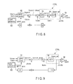
- FIG. 6 is a view for explaining another example of the MPPT timing signal MPPT_sync serving as a reference for the MPPT period during which the MPPT control is effected.
- a pulse that provides the MPPT timing signal MPPT_sync is generated by a signal generator SG.
- the signal generator SG may be mounted in one of the power conversion apparatuses PCS_1 to PCS_N connected in parallel, and it is connected to the other power conversion apparatuses through an auxiliary signal line (not shown). For example, when the system voltage cannot be detected from the electric power system due to a failure in the electric power system, e.g., power outage, a pulse generated by the signal generator SG is used as the MPPT timing signal MPPT_sync.
- the operation can be continued without stopping the power conversion apparatuses PCS_1 to PCS_N even though the electric power system has a failure.
- the auxiliary signal line connected between the power conversion apparatuses PCS_1 to PCS_N in this case does not require a complicated configuration since communication does not have to be performed through this line. Therefore, when transmitting the MPPT timing signal MPPT_sync from the power conversion apparatus having the signal generator SG mounted therein to another power conversion apparatus, the configuration of each power conversion apparatus is not complicated, and a cost is not increased.
- the direct-current voltage input to the MPPT control unit 32 is a direct-current voltage acquired by subtracting a value, which is obtained by multiplying the converter input current Iconv by a resistance equivalent value (droop gain) k1, from the converter input voltage Vconv.
- the resistance equivalent value k1 is a value simulating a resistance connected to the input end of the power conversion apparatus in series.
- the control is equivalent to that in a configuration where a resistor is connected to the input end of the power conversion apparatus, and the resistor actually does not have to be connected.
- the reference voltage Vconv* output from the MPPT control unit is subtracted by the direct-current voltage (Voncv-k1 ⁇ Iconv) input to the MPPT control unit 32, and a resultant voltage is input to the voltage control unit 34.
- the voltage control unit 34 Based on an input voltage difference value (Vconv*-(Vconv-k1xIconv)), the voltage control unit 34 outputs a reference current Iconv* by which this difference becomes zero.
- the converter input current Iconv is subtracted from the reference current Iconv* output from the voltage control unit 34, and a resultant current is input to the current control unit 36.
- the current control unit 36 controls in such a manner that this difference becomes zero and outputs a voltage direction value Vpwm_ref for the PWM comparator 38.
- the PWM comparator 38 compares the voltage direction value Vpwm_ref output from the current control unit 36 with a triangular wave voltage Vtri and outputs a PWM signal Vpwm of a predetermined duty ratio.
- the PWM signal Vpwm is applied to the gate electrode of the switch Sw_chop of the DC-DC converter unit 10 depicted in FIG. 1 .
- adjusting the duty ratio of the PWM signal Vpwm enables adjusting an ON period of the switch Sw_chop, and a value of the direct-current voltage output to the DC-AC inverter unit 20 can be adjusted by effecting boosting in the DC-DC converter unit 10.
- the power conversion apparatus of this embodiment it is possible to provide the power conversion apparatus that can be independently operated in parallel.
- a power conversion apparatus according to a second embodiment will now be described with reference to the drawings. It is to be noted that, in the following description, like reference numerals denote structures equal to those in the power conversion apparatus according to the first embodiment to omit explanation thereof.
- the power conversion apparatus according to this embodiment is different from the first embodiment in a control block that controls a gate terminal potential of a switch Sw_chop of a DC-DC converter unit 10.
- FIG. 7 shows an example of a control block that controls a gate terminal potential of the switch Sw_chop in the DC-DC converter unit 10.
- the control block depicted in FIG. 7 comprises an MPPT control unit 72 which receives a direct current (a converter input current Iconv-Vconv/k1) and a converter input voltage Vconv, a control unit CTRL including a current control unit (ACR: Automatic Current Regulator) 74 which performs PI control, and a PWM comparator 76.
- ACR Automatic Current Regulator
- An MPPT timing signal MPPT_sync is input to the MPPT control unit 72.
- the MPPT timing signal MPPT_sync adopted in this embodiment is generated from a zero-cross signal of a system voltage like the first embodiment.
- the MPPT control unit 72 can synchronously operate even if the power conversion apparatuses are connected in parallel. Therefore, the power conversion apparatus does not have to be provided with a communicating function, a complicated configuration can be avoided, and the individual power conversion apparatuses can independently operate.
- the signal generator SG may be configured to be capable of generating the MPPT timing signal MPPT_sync.
- the power conversion apparatuses are connected through the auxiliary signal line, and the MPPT timing signal MPPT_sync output from the signal generator SG is input to all the power conversion apparatuses connected in parallel.
- the direct current input to the MPPT control unit 72 is a direct current acquired by subtracting from the converter input current Iconv a value obtained by dividing the converter input voltage Vconv by the resistance equivalent value k1.
- the resistance equivalent value k1 simulates a resistance connected to the input end of the power conversion apparatus in series.
- the control is equivalent to that in a configuration where a resistor is connected to the input end of the power conversion apparatus, and the resistor actually does not have to be connected.
- the direct current (Iconv-Vconv/kl) input to the MPPT control unit 72 is subtracted from the reference current Iconv* output from the MPPT control unit 72, and a resultant current is input to the current control unit 74.
- the current control unit 74 controls in such a manner that this difference value becomes zero and outputs a voltage direction value Vpwm_ref for the PWM comparator 76.
- the PWM comparator 76 compares the voltage direction value Vpwm_ref output from the current control unit 74 with a triangular wave voltage Vtri and outputs a PWM signal Vpwm of a predetermined duty ratio.
- the PWM signal Vpwm is applied to the gate electrode of the switch Sw_chop in the DC-DC converter unit 10 depicted in FIG. 1 .
- adjusting the duty ratio of the PWM signal Vpwm enables adjusting an ON period of the switch Sw_chop, and a value of the direct-current voltage output to the DC-AC inverter unit 20 can be adjusted by effecting boosting in the DC-DC converter unit 10.
- the power conversion apparatus of this embodiment it is possible to provide the power conversion apparatus that can be independently operated in parallel.
- a power conversion apparatus according to a third embodiment will now be described with reference to the drawings.
- the power conversion apparatus according to this embodiment is different from the first embodiment in a control block that controls a gate terminal potential of a switch Sw_chop of a DC-DC converter unit 10.
- FIG. 8 shows an example of a control block that controls a gate terminal potential of the switch Sw_chop in the DC-DC converter 10 according to this embodiment.
- the control block depicted in FIG. 8 comprises an MPPT control unit 82 that receives a converter input voltage Vconv and a converter input current Iconv, a control unit CTRL including a voltage control unit (AVR: Automatic Voltage Regulator) 84 which performs PI control and a current control unit (ACR: Automatic Current Regulator) 86 which performs PI control, and a PWM comparator 88.
- AVR Automatic Voltage Regulator
- ACR Automatic Current Regulator
- An operation of the MPPT control unit 82 is the same as the operation of the MPPT control unit 32 according to the first embodiment.
- An MPPT timing signal MPPT_sync is input to the MPPT control unit 82.
- the MPPT timing signal MPPT_sync adopted in this embodiment is generated from a zero-cross signal of a system voltage like the first embodiment.
- the MPPT control unit 32 can synchronously operate even though the power conversion apparatuses are connected in parallel. Therefore, each power conversion apparatus does not have to be provided with a communicating function, a complicated configuration can be avoided, and each power conversion apparatus can independently operate.
- a signal generator SG may be configured to be capable of generating the MPPT timing signal MPPT_sync.
- the power conversion apparatuses are connected through an auxiliary signal line, and the MPPT timing signal MPPT_sync output from the signal generator SG is input to all the power conversion apparatuses connected in parallel.
- the MPPT control unit 82 outputs a reference voltage Vconv*.
- the feedback converter voltage value ⁇ Vconv of the droop control is a value obtained by multiplying a sign k3 which represents minus (-) when larger than a maximum power point due to the MPPT control for fluctuating a voltage or a plus (+) when smaller than the maximum power point by a value obtained by multiplying the reference current Iconv* by a droop gain k2.
- the droop gain k2 simulates a resistance connected to an input end of the power conversion apparatus in series.
- the voltage control unit 84 outputs the reference current Iconv* by which an input difference between the voltage Vconv*_droop after the droop control and the converter input voltage Vconv (Vconv*_droop-Vconv) becomes zero.
- the reference current Iconv* is compared with the converter input current Iconv, and its difference (Iconv*-Iconv) is input to the current control unit 86.
- the current control unit 86 controls in such a manner that this difference value becomes zero and outputs a voltage direction value Vpwm_ref for the PWM comparator 88.
- the PWM comparator 88 compares the voltage direction value Vpwm_ref output from the current control unit 86 with a triangular wave voltage Vtri and outputs a PWM signal Vpwm of a predetermined duty ratio.
- the PWM signal Vpwm is applied to a gate electrode of a switch Sw_chop in the DC-DC converter unit 10 depicted in FIG. 1 .
- adjusting the duty ratio of the PWM signal Vpwm enables adjusting an ON period of the switch Sw_chop, and a value of the direct-current voltage output to the DC-AC inverter unit 20 can be adjusted by effecting boosting in the DC-DC converter unit 10.
- the power conversion apparatus of this embodiment it is possible to provide the power conversion apparatus that can be independently operated in parallel.
- a power conversion apparatus according to a fourth embodiment will now be described with reference to the accompanying drawings.
- the power conversion apparatus according to this embodiment is different from the first embodiment in a control block that controls a gate terminal potential of a switch Sw_chop of a DC-DC converter unit 10.
- FIG. 9 shows an example of a control block that controls a gate terminal potential of the switch Sw_chop in the DC-DC converter unit 10.
- the control block depicted in FIG. 9 comprises an MPPT control unit 92 which receives a converter input voltage Vconv and a converter input current Iconv, a control unit CTRL including a current control unit (ACR: Automatic Current Regulator) 94 which performs PI control, and a PWM comparator 96.
- ACR Automatic Current Regulator
- An operation of the MPPT control unit 92 is the same as that of the MPPT control unit 72 according to the second embodiment.
- An MPPT timing signal MPPT_sync is input to the MPPT control unit 92.
- the MPPT timing signal MPPT_sync adopted in this embodiment is generated from a zero-cross signal of a system voltage like the first embodiment.
- the MPPT control unit 92 can synchronously operate even if the power conversion apparatuses are connected in parallel. Therefore, the power conversion apparatus does not have to be provided with a communicating function, a complicated configuration can be avoided, and the individual power conversion apparatuses can independently operate.
- a signal generator SG may be configured to be capable of generating the MPPT timing signal MPPT_sync.
- the power conversion apparatuses are connected through an auxiliary signal line, and the MPPT timing signal MPPT_sync output from the signal generator SG is input to all the power conversion apparatuses connected in parallel.
- the MPPT control unit 92 outputs a reference current Iconv*.
- the feedback converter current value ⁇ Iconv of the droop control performs a calculation by multiplying a sign k3 which represents plus (+) when larger than a maximum power point due to the MPPT control for fluctuating a current or minus (-) when smaller than the maximum power point with a value which is obtained by multiplying a voltage direction value Vpwm_ref by a droop gain 1/k2.
- k2 of the droop gain 1/k2 simulates a resistance connected to an input end of the power conversion apparatus in series.
- the current control unit 94 controls in such a manner that this difference becomes zero and outputs a voltage direction value Vpwm_ref for the PWM comparator 96.
- the PWM comparator 96 compares the voltage direction value Vpwm_ref output from the current control unit 94 with a triangular wave voltage Vtri and outputs a PWM signal of a predetermined duty ratio.
- the PWM signal Vpwm is applied to a gate electrode of the switch Sw_chop in the DC-DC converter unit 10 depicted in FIG. 1 .
- adjusting the duty ratio of the PWM signal Vpwm enables adjusting an ON period of the switch Sw_chop, and a value of the direct-current voltage output to the DC-AC inverter unit 20 can be adjusted by effecting boosting in the DC-DC converter unit 10.
- the power conversion apparatus of this embodiment it is possible to provide the power conversion apparatus that can be independently operated in parallel.
Landscapes
- Engineering & Computer Science (AREA)
- Power Engineering (AREA)
- Life Sciences & Earth Sciences (AREA)
- Sustainable Development (AREA)
- Sustainable Energy (AREA)
- Physics & Mathematics (AREA)
- Electromagnetism (AREA)
- General Physics & Mathematics (AREA)
- Radar, Positioning & Navigation (AREA)
- Automation & Control Theory (AREA)
- Dc-Dc Converters (AREA)
- Inverter Devices (AREA)
- Control Of Electrical Variables (AREA)
Applications Claiming Priority (1)
| Application Number | Priority Date | Filing Date | Title |
|---|---|---|---|
| JP2011032087A JP2012173773A (ja) | 2011-02-17 | 2011-02-17 | 電力変換装置 |
Publications (1)
| Publication Number | Publication Date |
|---|---|
| EP2495840A2 true EP2495840A2 (fr) | 2012-09-05 |
Family
ID=45655408
Family Applications (1)
| Application Number | Title | Priority Date | Filing Date |
|---|---|---|---|
| EP12154212A Withdrawn EP2495840A2 (fr) | 2011-02-17 | 2012-02-07 | Appareil de conversion de puissance |
Country Status (3)
| Country | Link |
|---|---|
| US (1) | US8531855B2 (fr) |
| EP (1) | EP2495840A2 (fr) |
| JP (1) | JP2012173773A (fr) |
Cited By (1)
| Publication number | Priority date | Publication date | Assignee | Title |
|---|---|---|---|---|
| US10008854B2 (en) | 2015-02-19 | 2018-06-26 | Enphase Energy, Inc. | Method and apparatus for time-domain droop control with integrated phasor current control |
Families Citing this family (16)
| Publication number | Priority date | Publication date | Assignee | Title |
|---|---|---|---|---|
| CN201563081U (zh) * | 2009-10-30 | 2010-08-25 | 国琏电子(上海)有限公司 | 太阳能转换模块及使用其的供电系统 |
| US9141123B2 (en) | 2012-10-16 | 2015-09-22 | Volterra Semiconductor LLC | Maximum power point tracking controllers and associated systems and methods |
| US8841787B1 (en) * | 2013-03-15 | 2014-09-23 | Caterpillar Inc. | Generator set adaptive droop control method |
| CN103760779A (zh) * | 2014-01-24 | 2014-04-30 | 广西电网公司电力科学研究院 | 一种直驱风力发电机组动态仿真模拟系统 |
| US9564830B2 (en) * | 2014-02-26 | 2017-02-07 | Fsp Technology Inc. | Control method of inverting apparatus for achieving MPPT and inverting apparatus thereof |
| CN104868764B (zh) * | 2014-02-26 | 2017-08-04 | 全汉企业股份有限公司 | 逆变装置及其电源转换方法 |
| KR101797270B1 (ko) * | 2014-04-16 | 2017-11-13 | 엘에스산전 주식회사 | 계통연계형 인버터 시스템의 제어장치 |
| CN104660051B (zh) * | 2014-10-17 | 2017-12-15 | 南京航空航天大学 | 一种基于电流源半桥变换器的光伏直流电路及其控制方法 |
| JP6531496B2 (ja) * | 2015-06-02 | 2019-06-19 | オムロン株式会社 | 蓄電池制御装置 |
| JP6546501B2 (ja) * | 2015-10-16 | 2019-07-17 | サンケン電気株式会社 | 蓄電装置 |
| JP6529921B2 (ja) * | 2016-03-25 | 2019-06-12 | 株式会社日立情報通信エンジニアリング | 電力変換装置 |
| US11381185B2 (en) | 2018-06-08 | 2022-07-05 | Kabushiki Kaishatoshiba | Power control circuit and power generation system including the same |
| JP7000369B2 (ja) * | 2018-06-08 | 2022-02-04 | 株式会社東芝 | 電力制御回路及びそれを備えた発電システム |
| CN110535135B (zh) * | 2019-07-10 | 2024-08-06 | 国网辽宁省电力有限公司电力科学研究院 | 一种基于微源与负载协同支撑的多能互补微电网多主从控制结构及方法 |
| CN115149802B (zh) * | 2022-09-01 | 2022-11-15 | 浙江日风电气股份有限公司 | 一种直流变换器的控制器、直流变换器 |
| DE102024125501A1 (de) * | 2024-09-05 | 2026-03-05 | Sma Solar Technology Ag | Verfahren und vorrichtung zum betrieb eines pv-generators am arbeitspunkt maximaler leistung |
Family Cites Families (5)
| Publication number | Priority date | Publication date | Assignee | Title |
|---|---|---|---|---|
| JP2000020150A (ja) * | 1998-06-30 | 2000-01-21 | Toshiba Fa Syst Eng Corp | 太陽光発電インバータ装置 |
| JP2001255949A (ja) * | 2000-03-13 | 2001-09-21 | Toshiba Corp | 太陽光発電インバータ装置 |
| US7248946B2 (en) * | 2004-05-11 | 2007-07-24 | Advanced Energy Conversion, Llc | Inverter control methodology for distributed generation sources connected to a utility grid |
| FR2885237B1 (fr) * | 2005-05-02 | 2007-06-29 | Agence Spatiale Europeenne | Dispositif de commande d'un convertisseur de tension continue a commutation et son utilisation pour maximiser la puissance delivree par un generateur photovoltaique |
| US20120075898A1 (en) * | 2010-09-28 | 2012-03-29 | Astec International Limited | Photovoltaic Power Converters and Closed Loop Maximum Power Point Tracking |
-
2011
- 2011-02-17 JP JP2011032087A patent/JP2012173773A/ja not_active Withdrawn
-
2012
- 2012-02-07 EP EP12154212A patent/EP2495840A2/fr not_active Withdrawn
- 2012-02-08 US US13/368,593 patent/US8531855B2/en not_active Expired - Fee Related
Non-Patent Citations (1)
| Title |
|---|
| None |
Cited By (3)
| Publication number | Priority date | Publication date | Assignee | Title |
|---|---|---|---|---|
| US10008854B2 (en) | 2015-02-19 | 2018-06-26 | Enphase Energy, Inc. | Method and apparatus for time-domain droop control with integrated phasor current control |
| US10951037B2 (en) | 2015-02-19 | 2021-03-16 | Enphase Energy, Inc. | Method and apparatus for time-domain droop control with integrated phasor current control |
| US11355936B2 (en) | 2015-02-19 | 2022-06-07 | Enphase Energy, Inc. | Method and apparatus for time-domain droop control with integrated phasor current control |
Also Published As
| Publication number | Publication date |
|---|---|
| JP2012173773A (ja) | 2012-09-10 |
| US20120212985A1 (en) | 2012-08-23 |
| US8531855B2 (en) | 2013-09-10 |
Similar Documents
| Publication | Publication Date | Title |
|---|---|---|
| US8531855B2 (en) | Power conversion apparatus | |
| US11929620B2 (en) | Maximizing power in a photovoltaic distributed power system | |
| US11031805B2 (en) | Power controller, power supply system and device and control method thereof | |
| CN102570804B (zh) | 直流电源转换模组、其控制方法、连接器及能量采集系统 | |
| US9048692B2 (en) | Controlled converter architecture with prioritized electricity supply | |
| US8704493B2 (en) | Battery system | |
| US20150236589A1 (en) | Power conditioner and method of controlling power conditioner | |
| KR20220103626A (ko) | 인버터 시스템, 인버터 시스템의 제어방법 및 병렬연결 인버터 시스템 | |
| CN115085245A (zh) | 光伏储能系统及其适用的控制方法 | |
| KR101920469B1 (ko) | 쿡 컨버터 기반의 계통 연계형 단일단 인버터 | |
| US12267012B2 (en) | Voltage balance systems and methods for multilevel converters | |
| CN114553138B (zh) | 光伏系统、光伏组件的故障检测方法及装置 | |
| EP2896100A1 (fr) | Procédé et appareil de production bidirectionnelle d'électricité dans un module de puissance | |
| JP2021027749A (ja) | 充放電制御装置およびそれを備えたバッテリ並びに直流給電システム | |
| JP2015133870A (ja) | 電力変換装置及び電力変換方法 | |
| JP2005269843A (ja) | 系統連系装置 | |
| US20170033678A1 (en) | Power converter for eliminating ripples | |
| US8928298B2 (en) | Power system and power controlling method and apparatus thereof | |
| KR101764651B1 (ko) | 태양광 발전 장치 연계형 전력공급장치 및 이의 제어 방법 | |
| WO2021229652A1 (fr) | Système d'électrolyse de l'eau et dispositif de commande de courant électrique | |
| CN109525007B (zh) | 电源控制器、供电系统及其控制方法 | |
| US11081961B2 (en) | Power convertor, power generation system, and power generation control method | |
| CN120016524A (zh) | 新能源储能子模块及其运行方法、储能系统及其运行方法 | |
| CN114402525A (zh) | 对来自光伏装置的电力进行供应的光伏优化器电力系统 | |
| WO2013002302A1 (fr) | Dispositif de stockage |
Legal Events
| Date | Code | Title | Description |
|---|---|---|---|
| PUAI | Public reference made under article 153(3) epc to a published international application that has entered the european phase |
Free format text: ORIGINAL CODE: 0009012 |
|
| 17P | Request for examination filed |
Effective date: 20120207 |
|
| AK | Designated contracting states |
Kind code of ref document: A2 Designated state(s): AL AT BE BG CH CY CZ DE DK EE ES FI FR GB GR HR HU IE IS IT LI LT LU LV MC MK MT NL NO PL PT RO RS SE SI SK SM TR |
|
| AX | Request for extension of the european patent |
Extension state: BA ME |
|
| STAA | Information on the status of an ep patent application or granted ep patent |
Free format text: STATUS: THE APPLICATION HAS BEEN WITHDRAWN |
|
| 18W | Application withdrawn |
Effective date: 20160926 |