EP2495921A1 - Détection de signaux améliorée pour l'atténuation de la distorsion dans des systèmes de transmission optique - Google Patents
Détection de signaux améliorée pour l'atténuation de la distorsion dans des systèmes de transmission optique Download PDFInfo
- Publication number
- EP2495921A1 EP2495921A1 EP11290109A EP11290109A EP2495921A1 EP 2495921 A1 EP2495921 A1 EP 2495921A1 EP 11290109 A EP11290109 A EP 11290109A EP 11290109 A EP11290109 A EP 11290109A EP 2495921 A1 EP2495921 A1 EP 2495921A1
- Authority
- EP
- European Patent Office
- Prior art keywords
- noise
- optical
- signal
- channel
- filter
- Prior art date
- Legal status (The legal status is an assumption and is not a legal conclusion. Google has not performed a legal analysis and makes no representation as to the accuracy of the status listed.)
- Granted
Links
Images



Classifications
-
- H—ELECTRICITY
- H04—ELECTRIC COMMUNICATION TECHNIQUE
- H04L—TRANSMISSION OF DIGITAL INFORMATION, e.g. TELEGRAPHIC COMMUNICATION
- H04L25/00—Baseband systems
- H04L25/02—Details ; arrangements for supplying electrical power along data transmission lines
- H04L25/03—Shaping networks in transmitter or receiver, e.g. adaptive shaping networks
- H04L25/03006—Arrangements for removing intersymbol interference
- H04L25/03178—Arrangements involving sequence estimation techniques
- H04L25/03248—Arrangements for operating in conjunction with other apparatus
- H04L25/03299—Arrangements for operating in conjunction with other apparatus with noise-whitening circuitry
Definitions
- the present document relates to optical transmission systems.
- the present document relates to a system and method for detecting symbols at an optical receiver from an optical signal which has been submitted to distortion in an optical transmission medium.
- Multi-level modulation formats combined with polarization multiplexing as well as digital coherent detection techniques are extensively investigated.
- PDM-QPSK polarization division multiplexed quadrature phase shift keying
- Another approach may be to further increase the spectral efficiency of 100Gb/s systems by tightly packing conventional WDM channels.
- the grid of the WDM channels may be reduced, i.e. the frequency spacing between adjacent WDM channels may be reduced.
- Transmissions with 3b/s/Hz or 4b/s/Hz spectral efficiency may be achieved using 100Gb/s PDM-QPSK channels over a 33GHz and 25GHz-grid respectively.
- a semi-flexible system architecture may be set up having a granularity of e.g. 12.5GHz (starting from an ITU grid) to define channel slots, instead of having a fixed 50GHz grid. This would enable to vary channel packing depending on an optimized trade-off between optical path impairments and required capacity.
- FIG. 1 An example implementation of a flexible grid system is shown in Fig. 1 .
- the upper diagram shows a conventional fixed WDM grid with a spacing of 50GHz.
- the lower diagram shows a flexible grid system comprising WDM channels with a varying granularity, e.g. a granularity of 25GHz or 50GHz, depending on the wavelength ⁇ .
- Each WDM channel may carry 100 Gb/s channels.
- the spectral grid gets tighter and/or when using larger overheads, the spectral information of adjacent channels tend to overlap (as shown in the lower diagram of Fig. 1 ). This typically leads to a QoT (Quality of Transmission) decrease for the WDM channels which are concerned by the channel overlap.
- QoT Quality of Transmission
- ISI intersymbol interference
- cross-talk penalties An inherent drawback of tightly filtering WDM channels is the increase of intersymbol interference (ISI) and cross-talk penalties. Consequently, it is important in the context of the development of ultra-dense WDM packing in optical networks to have receivers that have an increased performance under such conditions, i.e. under channel conditions with high ISI and cross-talk penalties.
- a further approach to increase the spectral efficiency of optical transmission systems such as 100 Gb/s systems is the use of multimode fibres.
- This approach may be used standalone or in addition to a fixed or flexible WDM grid.
- the use of multimode fibres may be used to at least partially overcome the nonlinear limitations of single mode transmission systems.
- Multimode fibres may be exploited mainly for two different purposes: a) to increase system capacity by using different modes to transmit different information and b) to reduce the reach limitation induced by nonlinearities when transmitting a single mode. These benefits may be achieved due to a larger effective area of multimode fibres compared to single-mode fibres.
- multi-mode fibres have a larger core-size than single-mode fibres, they support more than one propagation mode; hence the transmission with multi-mode fibres may be limited by modal dispersion, unlike the transmission with single mode.
- modal dispersion typically originates from different propagating speeds of different optical modes at the same wavelength supported by the multimode fibre.
- Modal dispersion acts as an in-band distortion to optical signals transmitted over a multimode fibre.
- the signal also suffers from crosstalk induced by co-propagating wavelength channels, as depicted in Fig. 1 .
- the present document suggests the use of detection schemes which are based on the observation of a sequence of received symbols.
- detection schemes are well-suited for detecting signals which have been submitted to tightly filtered optical channels and/or channels which suffer from in-band distortions such as modal dispersion or in-band cross-talk generated at optical nodes coming from co-propagating channels.
- the transmitted signal has memory due to the tight filtering within the tightly packed WDM channels, i.e. when the signals transmitted in successive symbol intervals are interdependent, the optimum detector is indeed a detector that bases its decisions on the observation of a sequence of received signals over successive signal intervals.
- the present document addresses the particular issue of a detection scheme which takes into account the cross-talk or interference between adjacent WDM channels and/or the in band distortions caused by modal dispersion or nodes. This is particularly relevant for WDM systems having a reduced channel spacing between adjacent WDM channels and/or WDM systems using multimode fibers.
- a detection unit configured to detect a symbol from a received digital signal.
- the received digital signal may have been derived from an optical signal which has been transmitted over a first optical transmitted channel (which may also be referred to briefly as an optical channel) and which has been submitted to noise.
- the digital signal may have been derived from the optical signal using coherent optical detection which translates into the electrical domain all the characteristics of the optical signal.
- the received digital signal may have been obtained from an optical signal which has incurred distortions (i.e. noise) during the transmission via the first optical transmitted channel, e.g. a WDM channel transmitted over an optical fiber.
- the optical transmitted channel may be a certain optical mode of a multi-mode fiber. As such, the optical transmitted channel may be a particular optical mode transmitted over a multi-mode fiber at a particular WDM wavelength.
- the detection unit may comprise a noise whitening filter unit.
- the noise whitening filter unit may be configured to filter the received digital signal using a noise whitening filter.
- the noise whitening filter may be configured to whiten the noise. That is, the noise of the received digital signal at the input of the noise whitening filter may be colored, i.e. the noise may have a power spectral density which is not flat.
- the noise of the received digital signal may be whitened, i.e. its power spectral density may have been flattened compared to the power spectral density of the noise at the input of the noise whitening filter unit.
- the noise whitening filter may be based on an estimate of the power spectral density of the noise.
- the noise whitening filter may be a finite impulse response filter comprising N filter coefficients.
- the N filter coefficients may be determined based on the estimate of the power spectral density of the noise at the input of the filter unit and/or at the output of the filter unit.
- the estimate of the power spectral density of the noise may be determined based on characteristics of the first optical transmitted channel and/or optical transmitted channel(s) adjacent to the first optical transmitted channel.
- the detection unit may further comprise a maximum likelihood sequence (MLSE) detector, downstream of the noise whitening filter unit.
- the MLSE detector may be configured to detect the symbol from the filtered digital signal at a given time instant, while taking into account the information carried by one or more symbols of one or more previous time instants.
- the MLSE detector may be configured to execute a Viterbi algorithm in order to detect the symbol.
- the estimate of the power spectral density of the noise may be determined based on one or more of: characteristics of the first optical transmitted channel; characteristics of a lower adjacent optical transmitted channel, using a wavelength lower than a wavelength of the optical transmitted channel; and/or characteristics of a higher adjacent optical transmitted channel, using a wavelength higher than the wavelength of the optical transmitted channel.
- the optical transmitted channels may be WDM channels of an optical WDM signal.
- the lower adjacent optical transmitted channel, the first optical transmitted channel and the higher adjacent optical transmitted channel may correspond to three adjacent, e.g. directly adjacent, WDM channels on a WDM grid.
- adjacent optical transmitted channels may be different optical modes within a multi-mode fiber.
- the characteristics of the optical transmitted channels which are used to determine the estimate of the power spectral density may be one or more of: baud rate of the transmitted channel, bandwidth of the transmitted channel, modulation scheme of the transmitted channel, and/or channel width of the transmitted channel.
- the detection unit may comprise a filter library, wherein the filter library may comprise a plurality of noise whitening filters associated with a plurality of estimates of the power spectral density of the noise, respectively.
- the plurality of noise whitening filters may be associated with a plurality of combinations of characteristics of the first optical transmitted channel, the lower adjacent optical transmitted channel and/or the higher adjacent optical transmitted channel.
- the filter library may be a look up table allowing the look up of a particular noise whitening filter in dependence of combinations of the characteristics of the first optical transmitted channel, the lower adjacent optical transmitted channel and/or the higher adjacent optical transmitted channel.
- the detection unit may comprise a characteristics reception unit configured to receive information on the characteristics of the optical transmitted channel(s). Such information on the characteristics of the first, the lower adjacent and/or the higher adjacent optical transmitted channels may be received from a control plane of the optical transmission network. Furthermore, the detection unit may comprise a filter selection unit configured to select the noise whitening filter from the filter library based on the received characteristics.
- the detection unit may further comprise an interference estimation unit configured to determine an estimate of the interference causing the coloring of the noise.
- This estimate of the interference causing the coloring of the noise may be based on the characteristics of the first optical transmitted channel and/or the characteristics of the lower adjacent and/or the higher adjacent transmitted channel. Alternatively or in addition, the estimate may be determined based on measurements on a predetermined transmitted signal, e.g. a predetermined pilot tone, as outlined in the following.
- the received digital signal may comprise a predetermined pilot tone.
- the pilot tone of the received digital signal may be orthogonal with respect to one or more pilot tones transmitted via adjacent optical transmitted channels.
- the adjacent optical transmitted channels may be different optical modes of a multi-mode fiber.
- the adjacent optical transmitted channels may be transmitted via adjacent, e.g. directly adjacent, WDM wavelengths.
- the detection unit may distinct the predetermined pilot tone of the received digital signal from the noise caused by the orthogonal pilot tones of adjacent optical transmitted channels.
- the detection unit may comprise a pilot tone subtraction unit configured to identify the predetermined pilot tone and to subtract the predetermined pilot tone from the received signal, thereby yielding a residual signal. Furthermore, the detection unit may comprise a noise analysis unit configured to determine the estimate of the power spectral density of the noise based on a power spectral density of the residual signal. Based on the power spectral density of the residual signal, the noise whitening filter, e.g. the coefficients of such a filter, may be determined in a filter determination unit.
- the detection unit may further comprise an equalizing unit upstream of the noise whitening filter unit.
- the equalizing unit may be configured to compensate chromatic distortion and/or polarization mode dispersion incurred by the optical signal in the first optical transmitted channel.
- the detection unit may comprise a polarization de-multiplexing unit upstream of the noise whitening filter unit.
- the polarization de-multiplexing unit may be configured to de-multiplex multiple polarizations of the optical signal.
- an optical receiver e.g. a coherent optical receiver, configured to detect a symbol from a received optical signal.
- the received optical signal may have been transmitted over a first optical transmitted channel and may have been submitted to noise.
- the receiver may comprise a reception unit configured to convert the optical signal into a (electrical) digital signal and a detection unit according to any of the aspects outlined in the present document.
- the detection unit may be configured to detect the symbol from the digital signal.
- an optical network may comprise a first optical transmitted channel configured to transmit an optical signal, wherein the optical signal is submitted to noise.
- the optical network may comprise a control plane.
- the control plane may be configured to gather and/or provide information on an estimate of a power spectral density of the noise.
- the control plane may have information on characteristics of the first optical transmitted channel and/or optical transmitted channels adjacent to the first optical transmitted channel, e.g. the lower adjacent and/or the higher adjacent optical transmitted channel.
- the optical network may comprise an optical receiver according to any of the aspects outlined in the present document. The optical receiver may be configured to detect a symbol from the optical signal.
- a method for detecting a symbol from a received digital signal may have been derived from an optical signal transmitted over a first optical transmitted channel and may have been submitted to noise.
- the method may comprise filtering the received digital signal using a noise whitening filter, wherein the noise whitening filter is configured to whiten the noise, and wherein the noise whitening filter is based on an estimate of a power spectral density of the noise.
- the method may comprise detecting the symbol from the filtered digital signal at a given time instant using maximum likelihood sequence detection, while taking into account one or more symbols of one or more previous time instants.
- a software program is described.
- the software program may be stored on a computer-readable medium (which may be tangible or otherwise non-transitory) as instructions that are adapted for execution on a processor and for performing the aspects and features outlined in the present document when carried out on a computing device.
- a storage medium comprising a software program
- the storage medium may be memory (e.g. RAM, ROM, etc.), optical media, magnetic media and the like.
- the software program may be adapted for execution on a processor and for performing the aspects and features outlined in the present document when carried out on a computing device.
- the computer program product may comprise executable instructions for performing the aspects and features outlined in the present document when executed on a computing device.
- ISI intersymbol interference
- the filtering effects of the optical path such as CD (chromatic dispersion) and PMD (polarization mode dispersion), i.e. the linear transfer function of the optical path or optical channel
- CD chromatic dispersion
- PMD polarization mode dispersion
- FIR finite impulse response
- an optical receiver (e.g. a coherent optical receiver) comprises various stages of digital signal processing.
- An example digital signal processing 100 is depicted in Fig. 2 for a coherent optical receiver of a polarization multiplexed (PMD) signal.
- CD compensation 102 follows 4 ADCs (analog-to-digital converters) 101 (corresponding to two sets of ADCs for each polarization).
- ADCs analog-to-digital converters
- a CMA (constant modulus algorithm) algorithm is used for polarization de-multiplexing and equalization 103.
- two distinct polarization de-multiplexed signals are obtained.
- the compensated signals are passed to symbol identification units 105, where the data samples are detected using the constellation associated with the underlying modulation scheme, e.g. QPSK.
- the quality of the overall transmission system may be measured using BER (bit error rate) or Q 2 -factor quality measures (reference sign 106).
- An MLSE detection scheme may be combined with linear equalization using FIR filters. It has been found that in optical communication, MLSE detection is particularly effective if several processing steps are performed prior to MLSE detection. As such, it is preferable to perform chromatic dispersion compensation 102 subsequent to analog-to-digital conversion 101 and prior to MLSE detection.
- MLSE processing may be used to detect the interdependence between successive symbol intervals (caused by ISI) by performing the symbol identification on a sequence of received symbols.
- ISI interdependence between successive symbol intervals
- WDM channels and/or multimode fibers for the transmission this not only impacts the inter symbol interference.
- the use of a reduced WDM channel spacing also impacts the cross-talk between adjacent WDM channels. This cross-talk will lead to an increased noise contribution within a particular WDM channel caused by adjacent WDM channels.
- the use of multimode fibers leads to modal dispersion which leads to an increased noise contribution to the particular WDM channel.
- a maximum likelihood sequence detector 306 together with a whitening filter stage 301 (see Fig. 3 ).
- the whitening filter stage may be used to whiten the noise caused in a particular WDM channel by its adjacent WDM channels and/or by the modal dispersion.
- a whitening filter stage 301 which whitens the noise of the received signal and thereby improves the performance of the subsequent MLSE detector 306.
- the maximum likelihood sequence detector 306 i.e. the estimation of a sequence of symbols, can be processed through the Viterbi algorithm. Details on MLSE detection schemes are described in the documents Forney, G., Jr., "Maximum-likelihood sequence estimation of digital sequences in the presence of intersymbol interference," Information Theory, IEEE Transactions on , vol.18, no.3, pp. 363-378, May 1972 , or Forney, G.D., Jr., "The viterbi algorithm," Proceedings of the IEEE, vol.61, no.3, pp. 268-278, March 1973 or Digital Communications, John G. Proakis, 4th edition (New York: McGraw Hill), chapter 10 , for which the sections on MLSE are incorporated by reference.
- the Viterbi algorithm theoretically requires a white Gaussian noise at the input in order to perform optimally. It is therefore suggested to perform a per channel choice of the whitening filter and to apply the whitening filter to the received signal prior to MLSE processing 306.
- the selection of the whitening filter may not only depend on the processed channel slot, but also on the characteristics of adjacent WDM slots.
- the design of an appropriate noise whitening filter will be outlined for the situation where a flexible WDM grid is used. It will be outlined that in such case, it is beneficial that the filter depends on the characteristics of the received WDM channel and on the characteristics of its adjacent WDM channels.
- whitening filter design methods will be described which may be used when transmitting optical signals over multimode fibers. It should be noted that in a combined scenario the whitening filters may be designed by a combination of both design methods.
- the characteristics of the received channel i.e. of the channel from which data symbols are to be recovered.
- the characteristics may relate to the underlying modulation format and the transmitted bandwidth.
- knowledge of the characteristics of the left and/or right neighboring channels of the received channel may be available. This is applicable in the case of point-to-point transmission systems. Furthermore, this is applicable in the case of reconfigurable networks involving switching nodes distributed along the network. In the latter case, the characteristics of the receiving channel and its neighboring channels typically change in case of a reconfiguration of the network.
- the neighboring channels of a received channel change along the transmission path.
- the characteristics of the neighboring channels may be the average characteristics of all the transient neighboring channels of the received channel along the transmission path. The average may take into account the length of the partial transmission path along which a certain transient neighboring channel was adjacent or neighboring to the received channel.
- the characteristics of the neighboring channels may be dominated by a subset of the transient neighboring channels.
- the characteristics of the left neighboring channel may be dominated by the most impacting left transient neighboring channel and/or the characteristics of the right neighboring channel may be dominated by the most impacting right transient neighboring channel.
- the most impacting channel may be determined by a comparison of the transient neighboring channels with respect to the length of the partial transition path, and/or the modulation format, and/or the bit rate, and/or the channel width.
- This information regarding the characteristics of the different transmitted channels and the current network configuration may be passed to or may be available at a control plane 302 shown in Fig. 3 .
- a combination e.g. a linear combination, of the interferences incurred by a particular channel along the optical path can be derived.
- the most impacting adjacent interferers e.g. the left and right adjacent WDM channels, may be identified based on the characteristics of the adjacent channels (e.g. based on the modulation formats and bandwidth of the adjacent channels).
- the information regarding the interference situation on a particular WDM channel, caused by its adjacent WDM channels may be determined in a WDM channel planning unit 303. As outlined above, the interference situation is determined based on the knowledge on the characteristics of the particular WDM channel and its neighboring channels (and/or its transient neighboring channels).
- the information regarding the interference situation may be transmitted within the control plane, typically using GMPLS (Generalized Multiprotocol Label Switching).
- the information may be transmitted off-line in a static network or on-line periodically in a dynamic network environment.
- this information may be used to select the most appropriate noise whitening filter among the ones available in a library of digital filters stored in a LUT (Look up table).
- the information regarding the current interference situation may be used by a filter selection unit 304 to select an appropriate whitening filter.
- a list of available whitening filters may be stored in a library of available filters 305.
- the selected filter may then be loaded into the signal processing unit 300 of the (coherent) optical receiver, e.g. through a micro-controller.
- the selected filter may be loaded into a whitening filter unit 301 upstream of the MLSE detector 306.
- the filter which is to be applied to the received channel within the whitening filter unit 301 is selected from a Look-Up Table (LUT) among a list of predetermined digital filters 305.
- the filtering selection module 304 chooses the optimal filter to be used in the optical receiver according to the characteristics (e.g. the baud rate, modulation format, bandwidth, channel width, etc.) of the received channel and its adjacent channels provided by the WDM channel planning unit 303.
- the list of digital filters 301 may be made up of whitening filters which are predetermined as a function of the characteristics of the received channel and as a function of its surrounding channels. Such filters aim at whitening noise within the received signal in order to optimize the result of the following maximum likelihood sequence detector. This is illustrated in Fig. 4 .
- the whitening filter 301 copes with the noise within a received WDM channel, which is caused by the interference with its adjacent WDM channels.
- the whitening operation performed by the whitening filter 301 is directed at improving the performance of the equalization stage 306, which is typically performed by a Viterbi equalizer.
- the equalization through the Viterbi algorithm is altered when the spectral density of the additive noise viewed at the equalizer input 306 moves away from a white Gaussian noise. Therefore, it is suggested in the present document to add a (further) noise component to the received signal, in order to whiten the initial noise caused by adjacent channels of the received channel.
- Fig. 4 illustrates example power spectral densities 400 of the noise 404 in a WDM channel k (reference numeral 402), as well as in its neighboring channels k-1 (reference numeral 401) and k+1 (reference numeral 403).
- the power spectral density 405 of the noise in channel k is not constant. It can be considered as if the noise within channel k is colored.
- the whitening filter 301 may be used in order to add additional noise having a power spectral density 407, such that the resulting noise at the output of the whitening filter 301 has a constant power spectral density 405.
- the output signal of the whitening filter 301 comprises the signal which is to be detected, plus white Gaussian noise, in contrast to the input signal of the whitening filter 301 which comprises the signal which is to be detected, plus colored noise.
- pre-whitening filter 301 leads to an improvement of the bit error rate at the output of the maximum likelihood sequence detector 306, despite of an increase of the overall additive noise energy.
- the whitening filters 301 may be calculated by means of various spectral inversion methods, such as the Levinson-Durbin method. For this purpose, the knowledge of the power spectral density 404 of the noise within the adjacent channels viewed from the bandwidth of the received channel should be known. As indicated above, a plurality of whitening filters 301 may be determined a priori. These filters 301 may be determined based on the noise spectral density according to various spectral shapes of adjacent channel. The plurality of whitening filters 301 can be stored in the Look-Up Table 305 and can be applied to the received signal prior to the MLSE detection stage 306.
- the stored digital filters within the library 305 correspond to an appropriate trade-off between noise whitening and signal-to-noise ratio decrease for each situation regarding the different possible characteristics of the received channel and its surrounding channels.
- a precalculated filter is stored, typically as an N taps Finite Impulse Response (FIR) filter.
- the filter may be conveniently performed through a convolution operation in the time domain (or a multiplication in the frequency domain) between the digital data flow and the selected FIR filter.
- the whitening filter operation 301 should be performed before the maximum likelihood sequence detector 306 within the (coherent) optical receiver.
- the flexibility brought by the architecture shown in Fig. 3 allows for rapid switching from one filter shape to another one among those stored in the filter library 305.
- the architecture is therefore in line with the future dynamic and flexible optical networking evolutions and can match any change in the modulation format and bandwidth of the current channel and/or of its adjacent channels.
- the present document proposes a flexible solution to manage this effect.
- it is proposed to exploit the knowledge about the characteristics of the received channels and its adjacent channels, which may be available e.g. at the network control plane. This knowledge is used to improve the performance of coherent receivers using a maximum likelihood sequence detector.
- the optical receiver can be adapted rapidly to changing network and interference situations. This is particularly beneficial in the context of dynamic reconfigurable networks based on a flexible grid.
- the described method and system yields an improvement of the Quality of transmission for each WDM channel whatever the characteristics (bandwidth, modulation format, etc.) of the channel itself and of the neighboring channels.
- multimode fibers are a further approach to increasing the spectral efficiency of optical transmission systems. This approach may be used standalone or in addition to the other approaches outlined in the present document. It is proposed to use fibres with effective areas larger than standard single mode fibres such as multi-mode fibres. Such multimode fibres may be used to reduce the nonlinear limitations of complex modulation schemes and therefore to maintain the maximum obtainable reach with complex modulation formats.
- multi-mode fibres have higher pulse spreading rates than single mode fibres due to modal dispersion which limits a multi-mode fibre's information transmission capacity.
- the limit on "bit-rate times distance" of multi-mode fibres has been typically lower compared to single-mode fibres, when considering direct-detection.
- the application range of multi-mode fibres has been limited to short distances ( ⁇ 1,000 m), while single-mode fibres were used to reach much longer distances.
- Coherent detection offers access to all the characteristics of the optical field (amplitude, phase and polarization) and therefore may bring solutions to efficiently use multi-mode fibers. This may be achieved based on an appropriated digital signal processing (DSP) at the optical receiver.
- DSP digital signal processing
- a method to optimize the transmission over multi-mode fibers is proposed based on appropriate digital signal processing through enhanced noise analysis.
- the channel is not only affected by the cross-talk of different wavelength channels, but also by co-propagating modes, as depicted by the channel diagram 500 in Fig. 5.
- Fig. 5 illustrates a plurality of WDM channels 505, 515, 525 similar to the WDM channels illustrated in Fig. 1 .
- Fig. 5 also illustrates the passband filtering 510 of WDM channel 515 performed at the optical receiver.
- Fig. 5 shows the primary optical mode 511, as well as a plurality of co-propagating modes 512, 513. It can be seen that the plurality of modes of the adjacent /neighboring WDM channels 505, 525 interfere with the modes 511, 512, 513 of the received WDM channel 515.
- the whitening filters may be determined based on pilot tones inserted into the signal of a WDM channel prior to transmission, in order to estimate different sources of cross-talk that may result in performance penalty.
- the results of the analysis of the received pilot tones may be used to optimize key parameters of the coherent receiver and to adjust its settings.
- the knowledge of some key quantities, revealed by spectral analysis, may be used to take countermeasures for the correction or mitigation of impairments, like cross-talk induced by other wavelength channels and other co-propagating modes.
- PSD noise power spectral density function
- the whitening filter will optimize the operation of the maximum likelihood sequence estimation (MLSE) 306 with Viterbi algorithm.
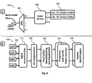
- Fig. 6a describes a possible scheme for detection in a coherent receiver 600 of an optical signal which has propagated over a multi-mode fibre.
- the different wavelength channels are separated by a wavelength selective switch (WSS) 601.
- WSS wavelength selective switch
- the different modes 511, 512, 513 of the multimode fibre are de-multiplexed in a mode de-multiplexing unit 622.
- the different modes 511, 512, 513 are detected by single mode coherent receivers 603.
- a non-optimal mode de-multiplexing 602 causes in-band distortion due to co-propagating modes, as depicted in Fig. 5 . These in-band distortions have to be dealt with by the digital signal processing in the single mode coherent receivers 603.
- Fig. 6b illustrates the main parts of the DSP realized in a coherent receiver 603. These parts have already been outlined in the context of Fig. 2 .
- the received signal is reconstructed in a signal reconstruction unit 611 using the information provided by the coherent mixer.
- digital chromatic dispersion mitigation 102, polarization demultiplexing and equalization 103, and frequency and carrier phase recovery 104 is performed. Once these steps have been performed, symbols can be identified 105 and thus the information is decoded.
- MLSE detection 306 for symbol identification 105 may be beneficial for compensating the modal distortions caused within the multimode fibre. Furthermore, it has been outlined that in order to improve the performance of MLSE detection 306, it is proposed to whiten the noise of the received signal prior to performing MLSE detection. For this purpose, an estimate of the noise power-spectral density (PSD) of the received signal may be determined, in order to subsequently determine an appropriate noise whitening filter.
- PSD noise power-spectral density
- the noise power-spectral density of the received signal may be estimated as outlined in the context of Fig. 7 . It is proposed to insert orthogonal pilot tones within each transmitted signal to efficiently determine the noise spectral analysis. In other words, it is suggested to insert a different pilot tone for each co-propagating mode within a WDM channel.
- the pilot tones attributed to the different co-propagating modes may be orthogonal with respect to one another, thereby allowing the different pilot tones to be isolated at the optical receiver. Alternatively or in addition, the pilot tones of adjacent WDM channels may be orthogonal with respect to one another.
- the orthogonal pilot tones are known at the optical receiver and may therefore be deducted from the received signal. This is illustrated in Fig. 7a .
- the power spectrum 701 of the received signal comprises contributions of the pilot tone, as well as contributions from the different optical modes of the adjacent WDM channels and the co-propagating modes of the received WDM channel.
- the spectrum of the pilot tone is known at the receiver, it may be subtracted from the power spectrum of the received signal, thereby yielding the noise power-spectral density 702.
- Knowing the noise power-spectral density 702 an appropriate noise whitening filter may be determined (based on the inverse of the noise power-spectral density 702). If the noise whitening filter is applied to the received signal, a received signal comprising a whitened noise power-spectral density 703 will be obtained.
- Fig. 7b shows the block diagram of an example coherent receiver comprising noise spectral analysis in combination with MLSE detection.
- MLSE detection 306 with Viterbi performs optimally when the noise of the received signal is white. Therefore, it is suggested that the noise is digitally whitened in order to mitigate the impact of the colored noise term.
- a whitening filter 715 may be designed in order to make the noise white. The filter may be designed by inversion techniques, as described above.
- the proposed method does not require knowledge about the source of the cross-talk.
- the proposed method only requires the use of a known pilot tone which is received at the optical receiver. This is not an issue since the inclusion of pilot tones may be required for other purposes (also for other channel estimation purposes) and the same pilot tones could be used for the estimation of the PSD.
- the whitening of the noise may decrease the original signal to noise ratio. Nevertheless, this operation usually leads to an improvement of performance at the output of the MLSE detection, since MLSE detection performs optimally when the noise is white. As already indicated above, the optimum whitening filter may be a trade-off between noise whitening and signal to noise ratio reduction.
- the method may be applied to the mitigation of the impact of in-band distortions in transmission networks using single-mode fibres.
- the pilot tone based filter determination scheme may be used in combination with the filter look-up table approach outlined in the context of Fig. 3 .
- the noise power spectral density determined through the use of the pilot tone may be considered to be a further characteristic of the optical transmitted channel.
- the noise power spectral density may be used in combination with other characteristics (e.g. bandwidth, modulation scheme, channel spacing) of the received channel and/or other characteristics (e.g. bandwidth, modulation scheme, channel spacing) of the neighbouring channels, in order to select an appropriate noise whitening filter from the library of digital filters 305.
- the methods and systems are particular useful for the processing of optical signals which have been transmitted over tightly spaced WDM channels and/or over multimode fibres.
- the use of tightly spaced WDM channels and/or the transmission over multimode fibres causes significant cross-talk from adjacent WDM channels and/or from co-propagating optical modes.
- the methods and systems outlined in the present document effectively mitigate the distortions caused by such cross-talk.
- the proposed methods and systems are based on the use of MLSE detection in combination with noise whitening filters.
- the noise whitening filters are determined based on appropriate estimates of the noise power spectrum density.
- steps of various above-described methods and components of described systems can be performed by programmed computers.
- program storage devices e.g., digital data storage media, which are machine or computer readable and encode machine-executable or computer-executable programs of instructions, wherein said instructions perform some or all of the steps of said above-described methods.
- the program storage devices may be, e.g., digital memories, magnetic storage media such as a magnetic disks and magnetic tapes, hard drives, or optically readable digital data storage media.
- the embodiments are also intended to cover computers programmed to perform said steps of the above-described methods.
- processor or “controller” should not be construed to refer exclusively to hardware capable of executing software, and may implicitly include, without limitation, digital signal processor (DSP) hardware, network processor, application specific integrated circuit (ASIC), field programmable gate array (FPGA), read only memory (ROM) for storing software, random access memory (RAM), and non volatile storage.
- DSP digital signal processor
- ASIC application specific integrated circuit
- FPGA field programmable gate array
- ROM read only memory
- RAM random access memory
- non volatile storage Other hardware, conventional and/or custom, may also be included.
- any block diagrams herein represent conceptual views of illustrative circuitry embodying the principles of the invention.
- any flow charts, flow diagrams, state transition diagrams, pseudo code, and the like represent various processes which may be substantially represented in computer readable medium and so executed by a computer or processor, whether or not such computer or processor is explicitly shown.
Landscapes
- Engineering & Computer Science (AREA)
- Power Engineering (AREA)
- Computer Networks & Wireless Communication (AREA)
- Signal Processing (AREA)
- Optical Communication System (AREA)
Priority Applications (1)
| Application Number | Priority Date | Filing Date | Title |
|---|---|---|---|
| EP11290109.5A EP2495921B1 (fr) | 2011-02-28 | 2011-02-28 | Détection de signaux améliorée pour l'atténuation de la distorsion dans des systèmes de transmission optique |
Applications Claiming Priority (1)
| Application Number | Priority Date | Filing Date | Title |
|---|---|---|---|
| EP11290109.5A EP2495921B1 (fr) | 2011-02-28 | 2011-02-28 | Détection de signaux améliorée pour l'atténuation de la distorsion dans des systèmes de transmission optique |
Publications (2)
| Publication Number | Publication Date |
|---|---|
| EP2495921A1 true EP2495921A1 (fr) | 2012-09-05 |
| EP2495921B1 EP2495921B1 (fr) | 2017-12-20 |
Family
ID=44312351
Family Applications (1)
| Application Number | Title | Priority Date | Filing Date |
|---|---|---|---|
| EP11290109.5A Active EP2495921B1 (fr) | 2011-02-28 | 2011-02-28 | Détection de signaux améliorée pour l'atténuation de la distorsion dans des systèmes de transmission optique |
Country Status (1)
| Country | Link |
|---|---|
| EP (1) | EP2495921B1 (fr) |
Cited By (4)
| Publication number | Priority date | Publication date | Assignee | Title |
|---|---|---|---|---|
| EP3131247A4 (fr) * | 2014-04-29 | 2017-04-26 | Huawei Technologies Co., Ltd. | Procédé de réception de signal et récepteur |
| CN107836100A (zh) * | 2015-08-31 | 2018-03-23 | 华为技术有限公司 | 用于使用稀疏不连续的时域导频的低复杂度isi估计的方法和装置 |
| WO2022166880A1 (fr) * | 2021-02-03 | 2022-08-11 | 维沃移动通信有限公司 | Procédé et appareil de traitement de signal, dispositif de communication et support de stockage |
| CN115242584A (zh) * | 2022-07-21 | 2022-10-25 | 苏州大学 | 一种优化基于查找表的mlse算法复杂度的方法和装置 |
Citations (2)
| Publication number | Priority date | Publication date | Assignee | Title |
|---|---|---|---|---|
| US6470047B1 (en) * | 2001-02-20 | 2002-10-22 | Comsys Communications Signal Processing Ltd. | Apparatus for and method of reducing interference in a communications receiver |
| US20080192870A1 (en) * | 2007-02-09 | 2008-08-14 | Research In Motion Limited | Apparatus, and associated method, for filtering a receive signal by adaptive operation of an input noise whitening filter |
Family Cites Families (3)
| Publication number | Priority date | Publication date | Assignee | Title |
|---|---|---|---|---|
| US5396519A (en) * | 1993-10-22 | 1995-03-07 | At&T Corp. | Method and apparatus for adaptively providing precoding and preemphasis conditioning to signal data for transfer over a communication channel |
| EP1508201B1 (fr) * | 2002-05-27 | 2006-08-02 | Telefonaktiebolaget LM Ericsson (publ) | Identification d'interférences par coloration |
| US7212593B2 (en) * | 2003-10-14 | 2007-05-01 | Telefonaktiebolaget Lm Ericsson (Publ) | Method of and apparatus for noise whitening filtering |
-
2011
- 2011-02-28 EP EP11290109.5A patent/EP2495921B1/fr active Active
Patent Citations (2)
| Publication number | Priority date | Publication date | Assignee | Title |
|---|---|---|---|---|
| US6470047B1 (en) * | 2001-02-20 | 2002-10-22 | Comsys Communications Signal Processing Ltd. | Apparatus for and method of reducing interference in a communications receiver |
| US20080192870A1 (en) * | 2007-02-09 | 2008-08-14 | Research In Motion Limited | Apparatus, and associated method, for filtering a receive signal by adaptive operation of an input noise whitening filter |
Non-Patent Citations (6)
| Title |
|---|
| AGAZZI O E ET AL: "Maximum likelihood sequence estimation in the presence of chromatic and polarization mode dispersion in intensity modulation/direct detection optical channels", 2004 IEEE INTERNATIONAL CONFERENCE ON COMMUNICATIONS ; ICC 2004 ; 20 - 24 JUNE 2004, PARIS, IEEE OPERATIONS CENTER, PISCATAWAY, NJ, USA, vol. 5, 20 June 2004 (2004-06-20), pages 2787 - 2793, XP010709741, ISBN: 978-0-7803-8533-7, DOI: 10.1109/ICC.2004.1313038 * |
| CHUNMIN XIA ET AL: "PMD-induced nonlinear penalty reduction in coherent polarization-multiplexed QPSK transmission", OPTICAL COMMUNICATION (ECOC), 2010 36TH EUROPEAN CONFERENCE AND EXHIBITION ON, IEEE, PISCATAWAY, NJ, USA, 19 September 2010 (2010-09-19), pages 1 - 3, XP031789939, ISBN: 978-1-4244-8536-9 * |
| FORNEY, G., JR.: "Maximum-likelihood sequence estimation of digital sequences in the presence of intersymbol interference", INFORMATION THEORY, IEEE TRANSACTIONS, vol. 18, no. 3, May 1972 (1972-05-01), pages 363 - 378, XP002900028, DOI: doi:10.1109/TIT.1972.1054829 |
| FORNEY, G.D., JR.: "The viterbi algorithm", PROCEEDINGS OF THE IEEE, vol. 61, no. 3, March 1973 (1973-03-01), pages 268 - 278 |
| JOHN G. PROAKIS: "Digital Communications", MCGRAW HILL |
| KHAIRUZZAMAN M ET AL: "Fiber-nonlinearity equalization by maximum-likelihood-sequence estimation (MLSE) in digital coherent receivers", OPTOELECTRONICS AND COMMUNICATIONS CONFERENCE, 2009. OECC 2009. 14TH, IEEE, PISCATAWAY, NJ, USA, 13 July 2009 (2009-07-13), pages 1 - 2, XP031518587, ISBN: 978-1-4244-4102-0 * |
Cited By (7)
| Publication number | Priority date | Publication date | Assignee | Title |
|---|---|---|---|---|
| EP3131247A4 (fr) * | 2014-04-29 | 2017-04-26 | Huawei Technologies Co., Ltd. | Procédé de réception de signal et récepteur |
| US9906310B2 (en) | 2014-04-29 | 2018-02-27 | Huawei Technologies Co., Ltd. | Signal receiving method and receiver |
| CN107836100A (zh) * | 2015-08-31 | 2018-03-23 | 华为技术有限公司 | 用于使用稀疏不连续的时域导频的低复杂度isi估计的方法和装置 |
| EP3323230A4 (fr) * | 2015-08-31 | 2018-09-26 | Huawei Technologies Co., Ltd. | Procédé et appareil pour estimation isi de faible complexité à l'aide de pilotes discontinus épars dans le domaine temporel |
| WO2022166880A1 (fr) * | 2021-02-03 | 2022-08-11 | 维沃移动通信有限公司 | Procédé et appareil de traitement de signal, dispositif de communication et support de stockage |
| CN115242584A (zh) * | 2022-07-21 | 2022-10-25 | 苏州大学 | 一种优化基于查找表的mlse算法复杂度的方法和装置 |
| CN115242584B (zh) * | 2022-07-21 | 2023-12-01 | 苏州大学 | 一种优化基于查找表的mlse算法复杂度的方法和装置 |
Also Published As
| Publication number | Publication date |
|---|---|
| EP2495921B1 (fr) | 2017-12-20 |
Similar Documents
| Publication | Publication Date | Title |
|---|---|---|
| EP2645599B1 (fr) | Optimisation souple du rapport signal sur bruit pour des systèmes WDM cohérents très denses | |
| KR101319906B1 (ko) | 코히어런트 광 시스템들에서 비-선형 손상 모니터링 및 완화를 위한 캐리어 위상 추정기 | |
| EP2975787B1 (fr) | Filtre numérique postérieur adaptatif et égaliseur de brouillage inter-symbole pour communication optique | |
| US9479247B2 (en) | Methods and apparatus for pre and post equalization in optical communications systems | |
| EP1617578B1 (fr) | Recepteur optique et systeme d'emission optique | |
| JP6325080B2 (ja) | 直交位相シフトキーイング変調された光信号からのデータ復元 | |
| JP6251269B2 (ja) | 400gの信号生成およびコヒーレント検出のためのシステムおよび方法 | |
| JP6135415B2 (ja) | 非線形歪み補償装置及び方法並びに光受信器 | |
| EP2168278B1 (fr) | Procédé et appareil servant à augmenter la capacité d'un canal de communication de données | |
| EP2495921B1 (fr) | Détection de signaux améliorée pour l'atténuation de la distorsion dans des systèmes de transmission optique | |
| US20160105245A1 (en) | Maximum likelihood sequence estimation of quadrature amplitude modulated signals | |
| JP7196995B2 (ja) | 波長多重光伝送システム、波長多重光伝送方法及びプログラム | |
| EP3131247B1 (fr) | Procédé de réception de signal et récepteur | |
| Ibrahim et al. | Towards a practical implementation of coherent WDM: analytical, numerical, and experimental studies | |
| Jain et al. | Analysis of bandwidth narrowing in wavelength selective switch enabled DP-64QAM systems with transceiver noise | |
| WO2022040775A1 (fr) | Systèmes et procédés d'atténuation du bruit de phase dans des supercanaux optiques | |
| JP6441751B2 (ja) | クロストーク補償装置及びクロストーク除去方法 | |
| Moreolo et al. | DSP-enabled optical OFDM for multiple-format and multi-rate/distance transmission | |
| Yamaoka et al. | Digital post-processing against inline spectrum narrowing caused by optical node traversals | |
| Eriksson et al. | Characterization of nonlinear fiber interactions using multidimensional mutual information over time and polarization | |
| Civelli et al. | Improved detection strategies for nonlinear frequency-division multiplexing | |
| Bagheri | Modeling the Phase Response of an Optical Filter with Application to Cascaded Filtering in an Optical Link | |
| Griesser et al. | Quaternary duobinary modulation for superchannels with sub-Nyquist subcarrier spacing | |
| EP2362557B1 (fr) | Estimation séquentielle de vraisemblance maximale dans un récepteur optique cohérent pour la tolérance de filtre optique | |
| Katz et al. | Time-division multilevel multiplexing communication method |
Legal Events
| Date | Code | Title | Description |
|---|---|---|---|
| PUAI | Public reference made under article 153(3) epc to a published international application that has entered the european phase |
Free format text: ORIGINAL CODE: 0009012 |
|
| AK | Designated contracting states |
Kind code of ref document: A1 Designated state(s): AL AT BE BG CH CY CZ DE DK EE ES FI FR GB GR HR HU IE IS IT LI LT LU LV MC MK MT NL NO PL PT RO RS SE SI SK SM TR |
|
| AX | Request for extension of the european patent |
Extension state: BA ME |
|
| 17P | Request for examination filed |
Effective date: 20130305 |
|
| 111Z | Information provided on other rights and legal means of execution |
Free format text: AL AT BE BG CH CY CZ DE DK EE ES FI FR GB GR HR HU IE IS IT LI LT LU LV MC MK MT NL NO PL PT RO RS SE SI SK SM TR Effective date: 20130410 |
|
| 17Q | First examination report despatched |
Effective date: 20131113 |
|
| RAP1 | Party data changed (applicant data changed or rights of an application transferred) |
Owner name: ALCATEL LUCENT |
|
| D11X | Information provided on other rights and legal means of execution (deleted) | ||
| GRAP | Despatch of communication of intention to grant a patent |
Free format text: ORIGINAL CODE: EPIDOSNIGR1 |
|
| STAA | Information on the status of an ep patent application or granted ep patent |
Free format text: STATUS: GRANT OF PATENT IS INTENDED |
|
| INTG | Intention to grant announced |
Effective date: 20170711 |
|
| GRAS | Grant fee paid |
Free format text: ORIGINAL CODE: EPIDOSNIGR3 |
|
| GRAA | (expected) grant |
Free format text: ORIGINAL CODE: 0009210 |
|
| STAA | Information on the status of an ep patent application or granted ep patent |
Free format text: STATUS: THE PATENT HAS BEEN GRANTED |
|
| AK | Designated contracting states |
Kind code of ref document: B1 Designated state(s): AL AT BE BG CH CY CZ DE DK EE ES FI FR GB GR HR HU IE IS IT LI LT LU LV MC MK MT NL NO PL PT RO RS SE SI SK SM TR |
|
| REG | Reference to a national code |
Ref country code: GB Ref legal event code: FG4D |
|
| REG | Reference to a national code |
Ref country code: CH Ref legal event code: EP |
|
| REG | Reference to a national code |
Ref country code: IE Ref legal event code: FG4D |
|
| REG | Reference to a national code |
Ref country code: AT Ref legal event code: REF Ref document number: 957320 Country of ref document: AT Kind code of ref document: T Effective date: 20180115 |
|
| REG | Reference to a national code |
Ref country code: DE Ref legal event code: R096 Ref document number: 602011044315 Country of ref document: DE |
|
| REG | Reference to a national code |
Ref country code: FR Ref legal event code: PLFP Year of fee payment: 8 |
|
| REG | Reference to a national code |
Ref country code: CH Ref legal event code: PCOW Free format text: NEW ADDRESS: SITE NOKIA PARIS SACLAY ROUTE DE VILLEJUST, 91620 NOZAY (FR) |
|
| RAP2 | Party data changed (patent owner data changed or rights of a patent transferred) |
Owner name: ALCATEL LUCENT |
|
| REG | Reference to a national code |
Ref country code: NL Ref legal event code: MP Effective date: 20171220 |
|
| PG25 | Lapsed in a contracting state [announced via postgrant information from national office to epo] |
Ref country code: SE Free format text: LAPSE BECAUSE OF FAILURE TO SUBMIT A TRANSLATION OF THE DESCRIPTION OR TO PAY THE FEE WITHIN THE PRESCRIBED TIME-LIMIT Effective date: 20171220 Ref country code: LT Free format text: LAPSE BECAUSE OF FAILURE TO SUBMIT A TRANSLATION OF THE DESCRIPTION OR TO PAY THE FEE WITHIN THE PRESCRIBED TIME-LIMIT Effective date: 20171220 Ref country code: FI Free format text: LAPSE BECAUSE OF FAILURE TO SUBMIT A TRANSLATION OF THE DESCRIPTION OR TO PAY THE FEE WITHIN THE PRESCRIBED TIME-LIMIT Effective date: 20171220 Ref country code: NO Free format text: LAPSE BECAUSE OF FAILURE TO SUBMIT A TRANSLATION OF THE DESCRIPTION OR TO PAY THE FEE WITHIN THE PRESCRIBED TIME-LIMIT Effective date: 20180320 |
|
| PGFP | Annual fee paid to national office [announced via postgrant information from national office to epo] |
Ref country code: DE Payment date: 20180219 Year of fee payment: 8 Ref country code: GB Payment date: 20180216 Year of fee payment: 8 |
|
| REG | Reference to a national code |
Ref country code: LT Ref legal event code: MG4D |
|
| REG | Reference to a national code |
Ref country code: AT Ref legal event code: MK05 Ref document number: 957320 Country of ref document: AT Kind code of ref document: T Effective date: 20171220 |
|
| PG25 | Lapsed in a contracting state [announced via postgrant information from national office to epo] |
Ref country code: RS Free format text: LAPSE BECAUSE OF FAILURE TO SUBMIT A TRANSLATION OF THE DESCRIPTION OR TO PAY THE FEE WITHIN THE PRESCRIBED TIME-LIMIT Effective date: 20171220 Ref country code: LV Free format text: LAPSE BECAUSE OF FAILURE TO SUBMIT A TRANSLATION OF THE DESCRIPTION OR TO PAY THE FEE WITHIN THE PRESCRIBED TIME-LIMIT Effective date: 20171220 Ref country code: GR Free format text: LAPSE BECAUSE OF FAILURE TO SUBMIT A TRANSLATION OF THE DESCRIPTION OR TO PAY THE FEE WITHIN THE PRESCRIBED TIME-LIMIT Effective date: 20180321 Ref country code: HR Free format text: LAPSE BECAUSE OF FAILURE TO SUBMIT A TRANSLATION OF THE DESCRIPTION OR TO PAY THE FEE WITHIN THE PRESCRIBED TIME-LIMIT Effective date: 20171220 Ref country code: BG Free format text: LAPSE BECAUSE OF FAILURE TO SUBMIT A TRANSLATION OF THE DESCRIPTION OR TO PAY THE FEE WITHIN THE PRESCRIBED TIME-LIMIT Effective date: 20180320 |
|
| PG25 | Lapsed in a contracting state [announced via postgrant information from national office to epo] |
Ref country code: NL Free format text: LAPSE BECAUSE OF FAILURE TO SUBMIT A TRANSLATION OF THE DESCRIPTION OR TO PAY THE FEE WITHIN THE PRESCRIBED TIME-LIMIT Effective date: 20171220 |
|
| PG25 | Lapsed in a contracting state [announced via postgrant information from national office to epo] |
Ref country code: CZ Free format text: LAPSE BECAUSE OF FAILURE TO SUBMIT A TRANSLATION OF THE DESCRIPTION OR TO PAY THE FEE WITHIN THE PRESCRIBED TIME-LIMIT Effective date: 20171220 Ref country code: ES Free format text: LAPSE BECAUSE OF FAILURE TO SUBMIT A TRANSLATION OF THE DESCRIPTION OR TO PAY THE FEE WITHIN THE PRESCRIBED TIME-LIMIT Effective date: 20171220 Ref country code: EE Free format text: LAPSE BECAUSE OF FAILURE TO SUBMIT A TRANSLATION OF THE DESCRIPTION OR TO PAY THE FEE WITHIN THE PRESCRIBED TIME-LIMIT Effective date: 20171220 Ref country code: CY Free format text: LAPSE BECAUSE OF FAILURE TO SUBMIT A TRANSLATION OF THE DESCRIPTION OR TO PAY THE FEE WITHIN THE PRESCRIBED TIME-LIMIT Effective date: 20171220 Ref country code: SK Free format text: LAPSE BECAUSE OF FAILURE TO SUBMIT A TRANSLATION OF THE DESCRIPTION OR TO PAY THE FEE WITHIN THE PRESCRIBED TIME-LIMIT Effective date: 20171220 |
|
| PG25 | Lapsed in a contracting state [announced via postgrant information from national office to epo] |
Ref country code: RO Free format text: LAPSE BECAUSE OF FAILURE TO SUBMIT A TRANSLATION OF THE DESCRIPTION OR TO PAY THE FEE WITHIN THE PRESCRIBED TIME-LIMIT Effective date: 20171220 Ref country code: IS Free format text: LAPSE BECAUSE OF FAILURE TO SUBMIT A TRANSLATION OF THE DESCRIPTION OR TO PAY THE FEE WITHIN THE PRESCRIBED TIME-LIMIT Effective date: 20180420 Ref country code: PL Free format text: LAPSE BECAUSE OF FAILURE TO SUBMIT A TRANSLATION OF THE DESCRIPTION OR TO PAY THE FEE WITHIN THE PRESCRIBED TIME-LIMIT Effective date: 20171220 Ref country code: SM Free format text: LAPSE BECAUSE OF FAILURE TO SUBMIT A TRANSLATION OF THE DESCRIPTION OR TO PAY THE FEE WITHIN THE PRESCRIBED TIME-LIMIT Effective date: 20171220 Ref country code: AT Free format text: LAPSE BECAUSE OF FAILURE TO SUBMIT A TRANSLATION OF THE DESCRIPTION OR TO PAY THE FEE WITHIN THE PRESCRIBED TIME-LIMIT Effective date: 20171220 Ref country code: IT Free format text: LAPSE BECAUSE OF FAILURE TO SUBMIT A TRANSLATION OF THE DESCRIPTION OR TO PAY THE FEE WITHIN THE PRESCRIBED TIME-LIMIT Effective date: 20171220 |
|
| REG | Reference to a national code |
Ref country code: CH Ref legal event code: PL |
|
| REG | Reference to a national code |
Ref country code: DE Ref legal event code: R097 Ref document number: 602011044315 Country of ref document: DE |
|
| PG25 | Lapsed in a contracting state [announced via postgrant information from national office to epo] |
Ref country code: MC Free format text: LAPSE BECAUSE OF FAILURE TO SUBMIT A TRANSLATION OF THE DESCRIPTION OR TO PAY THE FEE WITHIN THE PRESCRIBED TIME-LIMIT Effective date: 20171220 |
|
| PLBE | No opposition filed within time limit |
Free format text: ORIGINAL CODE: 0009261 |
|
| STAA | Information on the status of an ep patent application or granted ep patent |
Free format text: STATUS: NO OPPOSITION FILED WITHIN TIME LIMIT |
|
| 26N | No opposition filed |
Effective date: 20180921 |
|
| REG | Reference to a national code |
Ref country code: IE Ref legal event code: MM4A |
|
| REG | Reference to a national code |
Ref country code: BE Ref legal event code: MM Effective date: 20180228 |
|
| PG25 | Lapsed in a contracting state [announced via postgrant information from national office to epo] |
Ref country code: DK Free format text: LAPSE BECAUSE OF FAILURE TO SUBMIT A TRANSLATION OF THE DESCRIPTION OR TO PAY THE FEE WITHIN THE PRESCRIBED TIME-LIMIT Effective date: 20171220 Ref country code: LI Free format text: LAPSE BECAUSE OF NON-PAYMENT OF DUE FEES Effective date: 20180228 Ref country code: CH Free format text: LAPSE BECAUSE OF NON-PAYMENT OF DUE FEES Effective date: 20180228 Ref country code: LU Free format text: LAPSE BECAUSE OF NON-PAYMENT OF DUE FEES Effective date: 20180228 |
|
| PG25 | Lapsed in a contracting state [announced via postgrant information from national office to epo] |
Ref country code: IE Free format text: LAPSE BECAUSE OF NON-PAYMENT OF DUE FEES Effective date: 20180228 |
|
| PG25 | Lapsed in a contracting state [announced via postgrant information from national office to epo] |
Ref country code: BE Free format text: LAPSE BECAUSE OF NON-PAYMENT OF DUE FEES Effective date: 20180228 Ref country code: SI Free format text: LAPSE BECAUSE OF FAILURE TO SUBMIT A TRANSLATION OF THE DESCRIPTION OR TO PAY THE FEE WITHIN THE PRESCRIBED TIME-LIMIT Effective date: 20171220 |
|
| REG | Reference to a national code |
Ref country code: DE Ref legal event code: R119 Ref document number: 602011044315 Country of ref document: DE |
|
| GBPC | Gb: european patent ceased through non-payment of renewal fee |
Effective date: 20190228 |
|
| PG25 | Lapsed in a contracting state [announced via postgrant information from national office to epo] |
Ref country code: DE Free format text: LAPSE BECAUSE OF NON-PAYMENT OF DUE FEES Effective date: 20190903 Ref country code: MT Free format text: LAPSE BECAUSE OF NON-PAYMENT OF DUE FEES Effective date: 20180228 Ref country code: GB Free format text: LAPSE BECAUSE OF NON-PAYMENT OF DUE FEES Effective date: 20190228 |
|
| PG25 | Lapsed in a contracting state [announced via postgrant information from national office to epo] |
Ref country code: TR Free format text: LAPSE BECAUSE OF FAILURE TO SUBMIT A TRANSLATION OF THE DESCRIPTION OR TO PAY THE FEE WITHIN THE PRESCRIBED TIME-LIMIT Effective date: 20171220 |
|
| PG25 | Lapsed in a contracting state [announced via postgrant information from national office to epo] |
Ref country code: PT Free format text: LAPSE BECAUSE OF FAILURE TO SUBMIT A TRANSLATION OF THE DESCRIPTION OR TO PAY THE FEE WITHIN THE PRESCRIBED TIME-LIMIT Effective date: 20171220 Ref country code: HU Free format text: LAPSE BECAUSE OF FAILURE TO SUBMIT A TRANSLATION OF THE DESCRIPTION OR TO PAY THE FEE WITHIN THE PRESCRIBED TIME-LIMIT; INVALID AB INITIO Effective date: 20110228 |
|
| PG25 | Lapsed in a contracting state [announced via postgrant information from national office to epo] |
Ref country code: MK Free format text: LAPSE BECAUSE OF NON-PAYMENT OF DUE FEES Effective date: 20171220 |
|
| PG25 | Lapsed in a contracting state [announced via postgrant information from national office to epo] |
Ref country code: AL Free format text: LAPSE BECAUSE OF FAILURE TO SUBMIT A TRANSLATION OF THE DESCRIPTION OR TO PAY THE FEE WITHIN THE PRESCRIBED TIME-LIMIT Effective date: 20171220 |
|
| REG | Reference to a national code |
Ref country code: DE Ref legal event code: R082 Ref document number: 602011044315 Country of ref document: DE Representative=s name: BARKHOFF REIMANN VOSSIUS, DE Ref country code: DE Ref legal event code: R081 Ref document number: 602011044315 Country of ref document: DE Owner name: WSOU INVESTMENTS, LLC, LOS ANGELES, US Free format text: FORMER OWNER: ALCATEL LUCENT, BOULOGNE-BILLANCOURT, FR |
|
| REG | Reference to a national code |
Ref country code: GB Ref legal event code: 732E Free format text: REGISTERED BETWEEN 20201022 AND 20201028 |
|
| P01 | Opt-out of the competence of the unified patent court (upc) registered |
Effective date: 20230606 |
|
| PGFP | Annual fee paid to national office [announced via postgrant information from national office to epo] |
Ref country code: FR Payment date: 20250725 Year of fee payment: 15 |