EP2495941B1 - Dispositif mobile amovible doté d'un module de contrôle et module de station d'accueil - Google Patents
Dispositif mobile amovible doté d'un module de contrôle et module de station d'accueil Download PDFInfo
- Publication number
- EP2495941B1 EP2495941B1 EP11157067.7A EP11157067A EP2495941B1 EP 2495941 B1 EP2495941 B1 EP 2495941B1 EP 11157067 A EP11157067 A EP 11157067A EP 2495941 B1 EP2495941 B1 EP 2495941B1
- Authority
- EP
- European Patent Office
- Prior art keywords
- control module
- docking station
- communication device
- docking
- module
- Prior art date
- Legal status (The legal status is an assumption and is not a legal conclusion. Google has not performed a legal analysis and makes no representation as to the accuracy of the status listed.)
- Active
Links
Images



Classifications
-
- H—ELECTRICITY
- H04—ELECTRIC COMMUNICATION TECHNIQUE
- H04M—TELEPHONIC COMMUNICATION
- H04M1/00—Substation equipment, e.g. for use by subscribers
- H04M1/02—Constructional features of telephone sets
- H04M1/0202—Portable telephone sets, e.g. cordless phones, mobile phones or bar type handsets
- H04M1/0254—Portable telephone sets, e.g. cordless phones, mobile phones or bar type handsets comprising one or a plurality of mechanically detachable modules
- H04M1/0256—Portable telephone sets, e.g. cordless phones, mobile phones or bar type handsets comprising one or a plurality of mechanically detachable modules wherein the modules are operable in the detached state, e.g. one module for the user interface and one module for the transceiver
-
- H—ELECTRICITY
- H04—ELECTRIC COMMUNICATION TECHNIQUE
- H04M—TELEPHONIC COMMUNICATION
- H04M1/00—Substation equipment, e.g. for use by subscribers
- H04M1/72—Mobile telephones; Cordless telephones, i.e. devices for establishing wireless links to base stations without route selection
- H04M1/724—User interfaces specially adapted for cordless or mobile telephones
- H04M1/72403—User interfaces specially adapted for cordless or mobile telephones with means for local support of applications that increase the functionality
- H04M1/72409—User interfaces specially adapted for cordless or mobile telephones with means for local support of applications that increase the functionality by interfacing with external accessories
- H04M1/72412—User interfaces specially adapted for cordless or mobile telephones with means for local support of applications that increase the functionality by interfacing with external accessories using two-way short-range wireless interfaces
Definitions
- the disclosure relates to mobile devices. More particularly, the disclosure relates to mobile devices that are physically separable into a control device and a portable docking station, which wirelessly communicates with the control device.
- Electronic devices can provide a variety of functions including, for example, telephonic functions, electronic messaging functions and other personal information manager (PIM) application functions.
- Handheld electronic devices can include mobile stations, such as cellular telephones, smart telephones, personal digital assistants (PDAs), laptop computers, and desktop computers.
- PDAs personal digital assistants
- Such electronic devices allow the user to perform several functions, including placing voice calls and interacting with content, including text messages, email messages, address books, calendars, task lists, word processing documents and browser content.
- Existing electronic devices are heavy and bulky. The weight and bulk of existing electronic devices are generally attributable to large-sized components, heavy batteries and connector terminals. What is needed is a technology that separates the electronic device into a light-weight wireless control module that communicates with a docking station module using a short range radio communication device and a docking station module that communicates with a cellular network using a long range radio communication device.
- FIG. 1 illustrates an exemplary embodiment of an operating environment for a communication system 100 that may include a number of modular communication devices 103, including mobile devices.
- the communication system 100 may be coupled to the modular communication devices 103 in any of several different ways.
- the modular communication devices 103 may be coupled to a wireless network 101, such as one or more of a Wireless Wide Area Network (WWAN) 102 and a Wireless Local Area Network (WLAN) 104, among other suitable network arrangements.
- WWAN Wireless Wide Area Network
- WLAN Wireless Local Area Network
- the modular communication devices 103 may be configured to communicate over both the WWAN 102 and WLAN 104, and to roam between these networks.
- the wireless network 101 may comprise multiple WWANs 102 and WLANs 104, among other configurations.
- the WWAN 102 may be implemented as any suitable wireless access network technology.
- the WWAN 102 may be implemented as a wireless network that includes a number of transceiver base stations 108 (one of which is shown in FIG. 1 ), where each of the base stations 108 provide wireless Radio Frequency (RF) coverage to a corresponding area or cell.
- the WWAN 102 typically is operated by a mobile network service provider that provides subscription packages to users of the modular communication devices 103.
- the WWAN 102 may conform to one or more of the following wireless network types: Mobitex Radio Network; DataTAC; GSM (Global System for Mobile Communication); GPRS (General Packet Radio System); TDMA (Time Division Multiple Access); CDMA (Code Division Multiple Access); CDPD (Cellular Digital Packet Data); iDEN (integrated Digital Enhanced Network); Ev-DO (Evolution-Data Optimized); CDMA2000; EDGE (Enhanced Data rates for GSM Evolution); UMTS (Universal Mobile Telecommunication Systems); HSPDA (High-Speed Downlink Packet Access); IEEE 802.16e (also referred to as Worldwide Interoperability for Microwave Access or "WiMAX”), or various other networks. While WWAN 102 is described herein as a "Wide-Area" network, that term is intended also to incorporate wireless Metropolitan Area Networks (WMAN) or other similar technologies for providing coordinated service wirelessly over an area larger than that covered by typical WLANs.
- WMAN Wireless Metropolitan Area Networks
- the WWAN 102 may communicate with a wireless network gateway 110 that couples the modular communication devices 103 to transport facilities 112.
- the transport facilities 112 couple the modular communication devices 103 to a wireless connector system 120.
- the transport facilities 112 may include one or more private networks or lines, the Internet, a virtual private network, or any other suitable network, among other transport facilities.
- the wireless connector system 120 may be operated, for example, by an organization or enterprise such as a corporation, university, or governmental department, among other organizations or enterprises, which allow access to a network 124, such as an internal or enterprise network (e.g., an intranet) and its resources.
- the wireless connector system 120 may be operated by a mobile network provider.
- the network 124 may be realized using the Internet rather than, or in addition to, an internal or enterprise network.
- the wireless network gateway 110 provides an interface between the wireless connector system 120 and the WWAN 102.
- the wireless network gateway 110 facilitates communication between the modular communication devices 103 and other devices (not shown) that may be connected, directly or indirectly, to the WWAN 102. Accordingly, communications sent via the modular communication devices 103 are transported via the WWAN 102, the wireless network gateway 110 and the transport facilities 112 to the wireless connector system 120. Communications sent from the wireless connector system 120 are received by the wireless network gateway 110 and transported via the WWAN 102 to the modular communication devices 103.
- the WLAN 104 includes a wireless network that conforms to IEEE 802.11x standards (sometimes referred to as Wi-Fi TM) such as, for example, the IEEE 802.11a, 802.11b and/or 802.11g standard.
- IEEE 802.11x standards sometimes referred to as Wi-Fi TM
- IEEE 802.11n IEEE 802.16e
- WiMAX Worldwide Interoperability for Microwave Access
- IEEE 802.20 also referred to as Mobile Wireless Broadband Access
- the WLAN 104 includes one or more wireless RF Access Points (AP) 114 (one of which is shown in FIG. 1 ) that collectively provide a WLAN coverage area.
- AP wireless RF Access Points
- the WLAN 104 may be a user's personal network, an enterprise network, or a hotspot offered by an Internet service provider (ISP), a mobile network provider, or a property owner in a public or semi-public area, for example.
- the access points 114 may be connected to an access point (AP) interface 116 that may connect to the wireless connector system 120 directly or indirectly.
- a direct connection may be provided when the access point 114 is part of an enterprise WLAN 104 in which the wireless connector system 120 resides.
- An indirect connection may be provided via the transport facilities 112, as indicated by the dashed signal line in FIG. 1 , if the access point 114 is a personal Wi-Fi network or Wi-Fi hotspot.
- a mechanism such as a virtual private network (VPN) may be used for securely connecting to the wireless connector system 120.
- the AP interface 116 may provide translation and routing services between the access points 114 and the wireless connector system 120 to facilitate communication, directly or indirectly, with the wireless connector system 120.
- the wireless connector system 120 may be implemented as one or more servers, and is typically located behind a firewall 113.
- the wireless connector system 120 manages communications, including email, Hypertext Transfer Protocol (HTTP), and HTTP Secure (HTTPS) communications to and from a set of managed modular communication devices 103.
- HTTP Hypertext Transfer Protocol
- HTTPS HTTP Secure
- the wireless connector system 120 also provides administrative control and management capabilities over users and modular communication devices 103 that may connect to the wireless connector system 120.
- the wireless connector system 120 allows the modular communication devices 103 to access the network 124 and connected resources and services such as a messaging server 132, for example, a Microsoft Exchange Server®, IBM Lotus Domino®, or Novell GroupWiseTM email server; a content server 134 for providing content, such as Internet content or content from an organization's internal servers; application servers 136 for implementing server-based applications, such as instant messaging (IM) applications to modular communication devices 103, and intranet file services; among other connected resources and services.
- a messaging server 132 for example, a Microsoft Exchange Server®, IBM Lotus Domino®, or Novell GroupWiseTM email server
- a content server 134 for providing content, such as Internet content or content from an organization's internal servers
- application servers 136 for implementing server-based applications, such as instant messaging (IM) applications to modular communication devices 103, and intranet file services; among other connected resources and services.
- IM instant messaging
- the wireless connector system 120 typically provides a secure exchange of data (e.g., email messages, personal information manager (PIM) data, and IM data) with the modular communication devices 103.
- data e.g., email messages, personal information manager (PIM) data, and IM data
- communications between the wireless connector system 120 and the modular communication devices 103 may be encrypted.
- communications are encrypted using a symmetric encryption key implemented using Advanced Encryption Standard (AES) or Triple Data Encryption Standard (Triple DES) encryption.
- AES Advanced Encryption Standard
- Triple DES Triple Data Encryption Standard
- Private encryption keys are generated in a secure, two-way authenticated environment and are used for both encryption and decryption of data.
- the private encryption key is stored only in the user's mailbox on the messaging server 132 and on the modular communication device 103, and can typically be regenerated by the user on modular communication devices 103.
- Data sent to the modular communication devices 103 is encrypted by the wireless connector system 120 using the private encryption key retrieved from the user's mailbox.
- the encrypted data when received on the modular communication devices 103, is decrypted using the private encryption key stored in memory.
- data sent to the wireless connector system 120 from the modular communication devices 103 is encrypted using the private encryption key stored in the memory of the modular communication device 103.
- the encrypted data when received on the wireless connector system 120, is decrypted using the private encryption key retrieved from the user's mailbox.
- the wireless network gateway 110 is adapted to send data packets received from the modular communication device 103 over the WWAN 102 to the wireless connector system 120.
- the wireless connector system 120 then sends the data packets to the appropriate connection point such as the messaging server 132 or the content servers 134 or the application server 136, or a combination of these.
- the wireless connector system 120 may send data packets received, for example, from the messaging server 132 or the content servers 134 or the application servers 136 or any combination of these, to the wireless network gateway 110 that then transmit the data packets to the destination modular communication device 103.
- the AP interfaces 116 of the WLAN 104 provide similar sending functions between the modular communication device 103, the wireless connector system 120 and network connection point, such as the messaging server 132, the content server 134, the application server 136, or any combination of these.
- the network 124 may comprise a private local area network (LAN), metropolitan area network (MAN), wide area network (WAN), the public Internet or combinations thereof.
- the network 124 may include virtual networks constructed using any of these networks, alone or in combination.
- the modular communication device 103 may connect to the wireless connector system 120 using a computer 117, such as a desktop or a notebook computer, via the network 124.
- a link 106 may be provided between the modular communication device 103 and the computer 117 for exchanging information between the modular communication device 103 and a computer 117 connected to the wireless connector system 120.
- the link 106 may include one or both of a physical interface or a short-range wireless communication interface.
- the physical interface may comprise one or a combination of an Ethernet connection, a Universal Serial Bus (USB) connection, a FirewireTM (also known as an IEEE 1394 interface) connection, or other serial data connections, via respective ports or interfaces of the modular communication device 103 and computer 117.
- the short-range wireless communication interface may be a personal area network (PAN) interface.
- the PAN interface is a wireless point-to-point connection implemented to connect the end points without physical cables.
- the short-range wireless communication interface may include one or a combination of: an infrared (IR) connection, such as an Infrared Data Association (IrDA) connection; a radio frequency (RF) connection, such as a Bluetooth® or IEEE 802.15.1 connection, UltraWideband (UWB) or IEEE 802.15.3a connection, or ZigBee or IEEE 802.15.4 connection; among other communication interfaces.
- IR infrared
- IrDA Infrared Data Association
- RF radio frequency
- the above-described communication system 100 is provided for illustration purposes only.
- the above-described communication system 100 may be implemented using any of a multitude of network configurations for use with the modular communication devices 103. Suitable variations of the communication system 100 will be readily appreciated by a person of ordinary skill in the art and are intended to fall within the scope of the present disclosure.
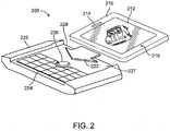
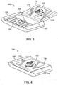
- FIGs. 2-4 illustrate an exemplary modular communication device 200 having a control module 210 and a docking station module 220 that operate together to provide mobile communication functionality.
- FIGs. 2-4 illustrate the control module 210 and the docking station module 220 positioned in various states, including an undocked state, a partially docked state and a fully docked state, respectively.
- Various types of coupling mechanisms may be provided to place the control module 210 and the docking station module 220 in the docked, partially docked and undocked states.
- a sliding mechanism may be provided to slide the control module 210 relative to the docking station module 220 in a direction shown by arrow 222 in FIG. 2 .
- the sliding mechanism transitions the control module 210 from the undocked state to the partially docked and the fully docked states.
- One of ordinary skill in the art will readily appreciate that other coupling mechanisms may be provided to dock and undock the control module 210 relative to the docking station module 220.
- FIG. 2 illustrates the control module 210 in the undocked state.
- the control module 210 uses a short-range radio device to communicate wirelessly with the docking station module 220.
- the short-range radio communication devices may employ any of various wireless protocols including the IEEE 802.15.x or the IEEE 802.11x protocols for wireless personal networks (WPANs), among other wireless protocols.
- the short-range radio communication devices may employ the Bluetooth® protocol (IEEE 802.15.1), the UltraWideband (UWB) protocol (IEEE 802.15.3a), the ZigBee protocol (IEEE 802.15.4) or the Wi-Fi protocol (IEEE 802.11x), among other wireless protocols.
- the wireless protocols enable the short-range radio devices to communication with other wireless devices that are located within the communication range, including other infrared devices or radio-frequency devices, among other wireless devices.
- the docking station module 220 may further include a long-range radio for wirelessly communicating with long-range communication systems, such as cellular radio communication systems or other long-range communication systems.
- long-range communication systems such as cellular radio communication systems or other long-range communication systems.
- the technology enables the control module 210 to access long-range communication capabilities of the docking station module 220 using the short-range communication radio communications.
- the technology enables the control module 210 to leverage the functionality of large, high power components in the docking station module 220, while benefitting from small, low power components associated with short-range radios.
- the technology provides a sleek control module 210 having full functionality of the associated docking station module 220.
- the control module 210 includes small-sized, low-power components while the docking station module 220 includes larger-sized, higher-power components.
- the control module 210 and the docking station module 220 exchange data wirelessly using short-range radios.
- the exchanged data includes data accessed by the docking station module 220 using the long-range radio, among other data sources.
- the docking station module 220 may include a processor or other component that coordinates data exchange between the short-range radio structure and the long-range radio structure, among other structures.
- control module 210 enable miniaturization through use of smaller, lighter-weight batteries in the control module 210.
- the docking station module 220 is equipped with larger, heavier-weight batteries.
- the control module 210 is further miniaturized by eliminating bulky connectors and wired input/output interfaces. The elimination of connectors and wired interfaces in the control module 210 provides an additional benefit of a substantially sealed structure that may be water-resistant or even water-proof, if all openings are sealed.
- the control module 210 may include a battery that is not accessible to users and is re-charged via the docking station module 220. To this end, the control module 210 may include contacts, such as insert molded contacts, for charging the battery of the control module.
- the control module 210 may include several components such as, a display 212, including a touch-sensitive display; a camera (not shown); a video recorder (not shown); an audio recorder (not shown); speakers 214; a microphone 216; external mechanical buttons; status indicators, such as light emitting diode (LED) status indicators; and a navigational tool (not shown); among other components.
- the control module 210 may be sized for cradling in one or both hands by an operator of the modular communication device 200.
- the display 212 may present a touch-sensitive virtual keyboard or other data entry interface that enables users to perform data entry, including textual data entry.
- the display content may be rotated within the display 212 from a vertical orientation to a horizontal orientation to provide a full QWERTY keyboard on the display 212.
- communication signals originating from or directed to the control module 210 may be processed at the docking station module 220.
- the control module 210 may be positioned in a partially docked state relative to the docking station module 220.
- the docking station module 220 may include an upper surface 227 having user input components thereon, such as a keyboard 224 and an auxiliary input device or navigation tool 226, among other user input components.
- the keyboard 224 and the navigation tool 226 may be positioned on the upper surface 227 to enable thumb-actuation of keys of the keyboard 224 and the navigation tool 226.
- One embodiment provides the navigation tool 226 in the form of an optical joystick that may be utilized to instruct two-dimensional cursor movement in substantially any direction on the display 212.
- the navigation tool 226 may act as an actuator when depressed like a button.
- the navigation tool 226 may include one of a track pad, a track ball, a touchpad, a pointing stick, a joystick, or a graphics tablet, among other navigation tools.
- the navigation tool 226 may be placed at an upper portion of the keyboard 224. In this location, the navigation tool 226 may avoid interference during keyboarding.
- the control module 210 may be situated to overlap the upper surface 227 of the docking station module 220 at any position between the upper portion of keyboard 224 and an upper edge 228 of the upper surface 227.
- the display content may be rotated within the display 212 from a vertical orientation to a horizontal orientation to enable viewing the display content while manipulating the keyboard 224 and the navigation tool 226.
- the display 212 may present a touch-sensitive data entry interface or a virtual keyboard that enables users to perform data entry, including textual data entry.
- the battery of the control module 210 may be charged while coupled to the docking station module 220. Otherwise, the control module 210 includes features and is configured to operate as described above with respect to FIG. 2 .
- the control module 210 may be positioned in a fully docked state relative to the docking station module 220. In the fully docked state, the control module 210 may overlap all or substantially all of the upper surface 227 of the docking station module 220. As a result, the control module 210 conceals the user input components provided on the docking station module 220.
- the display 212 in the fully docked state is configured to provide a touch-sensitive virtual keyboard or other data entry interface that enables users to perform data entry, including textual data entry. According to one embodiment, the display content may be rotated within the display 212 from a vertical orientation to a horizontal orientation to provide a full QWERTY keyboard on the display 212. As described below, communication signals originating from or directed to the control module 210 may be processed at the docking station module 220. Otherwise, the control module 210 includes features and is configured to operate as described above with respect to FIG. 2 .
- the docking station module 220 is a wearable docking device that is carried by the user and operated in close proximity to the control module 210.
- the docking station module 220 may be fastened by a quick release mechanism to a belt worn by the user.
- the docking station module 220 may be carried in a user's bag or purse, among being carried in other locations.
- the docking station module 220 is constructed to be larger than the control module 210 and may be sized for cradling in one or both hands by an operator of the modular communication device 200.
- the control module 210 and the docking station module 220 are positioned within a communication range of their corresponding short-wave radios.
- the docking station module 220 includes components for exchanging data messages with cellular networks or other networks, including the Internet.
- the docking station module 220 also includes components for performing voice communications, such as mobile telephone calls, using a cellular network or other network.
- the docking station module 220 further may include integrated input/output electrical contacts to enable wired data exchange and power re-charging, among providing other functions.
- the docking station module 220 may include a replaceable, high-capacity internal battery that may be employed to re-charge one or more batteries in the controller module 210.
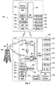
- FIG. 5 illustrates a block diagram 500 of the modular communication device 200, in accordance with an exemplary embodiment.
- the modular communication device 200 includes a control module block diagram 501 and a docking station module block diagram 502.
- the docking station module block diagram 202 includes a microprocessor 510 that controls operations of the docking station module 220.
- a long-range communication subsystem 520 is provided that performs long range communications, including transmission and reception, with the wireless network 530.
- the microprocessor 510 may be communicatively coupled to an auxiliary input/output (I/O) subsystem 226 of the docking station module 220.
- I/O auxiliary input/output
- the microprocessor 510 may be communicatively coupled to a serial port 512, such as a Universal Serial Bus port, that enables communications with other devices or systems.
- the display driver 513 may be communicatively coupled to the microprocessor 510 for generating images that are displayed to an operator of the modular communication device 200.
- the keyboard 224 may be communicatively coupled with the microprocessor 510.
- the docking station module 220 may include a speaker 515, a microphone 516, a random access memory (RAM) 517, and a flash memory 518, among other components. These components may be communicatively coupled to the microprocessor 510.
- Other components may be provided on the docking station module 220 and these other components may be optionally communicatively coupled to the microprocessor 510.
- Other communication subsystems 519 and other device subsystems 518 are generally indicated as being functionally connected with the microprocessor 510 as well.
- the control module block diagram 501 includes a microprocessor 503 that controls operations of the control module 210.
- the microprocessor 503 is electrically coupled with a short-range communication system 504 that communicates with a corresponding communication subsystem 519 of the docking station module 220.
- the control module 210 does not include a long-range communication system.
- the microprocessor 503 may be communicatively coupled to an auxiliary input/output (I/O) subsystem 505 of the control module 210.
- the microprocessor 503 may be communicatively coupled to a touch-sensitive display 506 that displays to an operator of the modular communication device 200.
- the control module 210 is equipped with a virtual keyboard 507 that is communicatively coupled with the microprocessor 503.
- the control module 210 may include a speaker 214, a microphone 216, a random access memory (RAM) 508, a camera 509, a video recorder 511, audio recorder 550, status indicator 551, and external buttons 552, among other components. These components may be communicatively coupled to the microprocessor 503. Other components may be provided on the control module 210 and these other components may be optionally communicatively coupled to the microprocessor 503.
- the technology provides an exemplary communication subsystem 519 in the docking station module 220 for wirelessly communicating with the control module 210.
- the docking station module 220 may include a short-range communication system.
- the short-range communication system 504 of the control module 210 and the communication subsystem 519 of the docking station module 220 may communicate using, for example, a BLUETOOTH® (IEEE 802.15.1) protocol, a ZigBee® (IEEE 802.15.4) protocol, an UltraWideband (IEEE 802.15.3a) protocol or a WI-FI® (IEEE 802.11x) protocol, among other communication protocols.
- the controller module 210 may be synchronized to communicate with a limited number of docking station modules 220.
- the controller module 210 may be synchronized to communicate with a single docking station module 220.
- the microprocessor 510 of the docking station module 220 and the microprocessor 503 of the control module 210 may be configured to perform operating system functions and to enable the execution of programs on the modular communication device 200. In some embodiments, less than all of the above components may be included in the control module 210 and the docking station module 220 of the modular communication device 200.
- the keyboard 224 of the docking station module 220 may not be provided as a separate component and instead may be integrated with a touch screen as described above.
- the auxiliary I/O subsystem 226, 505 may take the form of a variety of different navigation tools, including multi-directional or single-directional navigation tools.
- the navigation tools 226, 505 may include an optical navigation tool, a trackball navigation tool, a thumbwheel, a navigation pad, a joystick or a touch-sensitive interface, among other I/O interfaces.
- the navigation tool 226 of the docking station module 220 may be located on the upper surface 227 or may be located on any exterior surface of the docking station module 220.
- the navigation tool 505 of the control module 210 may be located on the display 212 surface or may be located on any exterior surface of the control module 210.
- the control module 210 may act as an auxiliary I/O subsystem for the docking station module 220. While the above examples are provided in relation to the auxiliary I/O subsystem 224, 505, other subsystems capable of providing input or receiving output from the docking station module 220 and the control module 210 are considered within the scope of this disclosure. Additional keyboard keys may be provided at the control module 210 and the docking station module 220 to perform function of escape keys, volume control keys, scrolling keys, power switches, or user programmable keys, and may likewise be programmed accordingly.
- the keyboard 224 of the docking station module 220 may include a plurality of keys that are physical in nature, such as actuable buttons. Alternatively, the keyboard 224 may be virtual or software in nature. Virtual keys typically represent physical keys on the display 212 of the control module 210 (referred to herein as "virtual keys"). It is also contemplated that user input may be provided as a combination of mechanical and virtual key types. Each key of the plurality of keys may be associated with at least one action, which can be the input of a character, a command or a function. In this context, "characters" are contemplated to exemplarily include alphabetic letters, language symbols, numbers, punctuation, insignias, icons, pictures, or blank space, among other characters.
- the indicia for the respective keys may be shown on the display 212 of the control module 210.
- the virtual keys may be enabled by touching the display 212, for example, with a stylus, finger, or other pointer, to generate the character or activate the indicated command or function.
- Some examples provide a display 212 that is capable of detecting a touch include resistive, capacitive, projected capacitive, infrared and surface acoustic wave (SAW) touch screens.
- SAW surface acoustic wave
- Physical and virtual keys may be combined in many different ways, as appreciated by those skilled in the art.
- the physical and virtual keys may be combined, such that the plurality of enabled keys for a particular program or feature of the modular communication device 200 are shown on the display 212 in a same configuration as the physical keys. Using this configuration, the operator may select the appropriate physical key corresponding to what is shown on the display 212. Thus, the desired character, command or function is obtained by depressing the physical key corresponding to the character, command or function displayed at a corresponding position on the display 212, rather than touching the actual key on the keyboard 224.
- a flash memory 530 may be provided to store an operating system 531, device programs 532 and data.
- the operating system 531 is generally configured to manage other programs 532.
- the programs 532 that may be stored in the flash memory 530 and may be executable on the microprocessor 510.
- the operating system 531 honors requests for services made by the programs 532, through predefined program interfaces, among other request types. More specifically, the operating system 531 typically determines the order in which the multiple programs 532 are executed on the microprocessor 510.
- the operating system 531 also may determine an execution time allotted for each program 532, manage sharing of the flash memory 530 among the multiple programs, handle input and output to and from other device subsystems 518, among performing other operations.
- the operating system 531 may be stored in the flash memory 530. In other embodiments, the operating system 531 may be stored in a read-only memory (ROM) or similar storage element (not shown). As those skilled in the art will appreciate, the operating system 531, device program 532 or parts thereof may be loaded in a RAM 517 or other volatile memory.
- ROM read-only memory
- the flash memory 530 may include programs 532 for execution on the docking station module 220, including a device state 533, an address book 534 and a personal information manager (PIM) 535, among other programs. Furthermore, the programs 532 and other information 536, including data, may be segregated upon storage in the flash memory 530 of the docking station module 220.
- programs 532 and other information 536 including data, may be segregated upon storage in the flash memory 530 of the docking station module 220.
- GPRS General Packet Radio Service
- UMTS Universal Mobile Telecommunication Service
- EDGE Enhanced Data for Global Evolution
- CDMA Code Division Multiple Access
- HSPA High-Speed Packet Access
- UMTS-TDD Universal Mobile Telecommunication Service Time Division Duplexing
- UMB Ultra Mobile Broadband
- WiMAX Worldwide Interoperability for Microwave Access
- the modular communication device 200 may use a unique identifier to enable the modular communication device 200 to transmit and receive signals from the communication network 540. Other systems may not use such identifying information. With a properly enabled modular communication device 200, two-way communication may be performed between the docking station module 220 and the communication network 540.
- the docking station module 220 may be configured for two-way communication to both transmit and receive information from the communication network 540.
- the communication transfer may be performed to or from the docking station module 220.
- the docking station module 220 may be equipped with an integral or internal antenna 521 for transmitting signals to the communication network 540.
- the docking station module 220 may be equipped with another antenna 522 for receiving communication from the communication network 540.
- these antennae 521, 522 may be combined into a single antenna (not shown).
- the antenna or antennae 521, 522 in another embodiment may be externally mounted on the docking station module 220.
- the docking station module 220 may include the communication subsystem 520 that supports the operational needs of the modular communication device 200.
- the communication subsystem 520 may include a transmitter 523 and a receiver 524, including an associated antenna or antennae 521, 522 as described above, local oscillators (LOs) 525, and a processing module that in the presently described exemplary embodiment is a digital signal processor (DSP) 526.
- LOs local oscillators
- DSP digital signal processor
- communication between the docking station module 220 and the wireless network 540 may be any type of communication that both the wireless network 540 and modular communication device 200 are enabled to support. In general, these communications may be classified as voice and data communications.
- Voice communication generally refers to communication in which signals for audible sounds are transmitted through the communication network 540 by the modular communication device 200.
- Data communication generally refers to all other types of communication that the modular communication device 200 is capable of performing within the constraints of the wireless network 540.
- FIGs. 1 and 5 are exemplary only and those persons skilled in the art will appreciate that additional elements and modifications may be necessary to make the modular communication device 200 operate in particular network environments.
- the illustrated embodiments disclose the modular communication devices 200 as smart phones.
- the modular communication devices 200 may include personal digital assistants (PDA), tablet computers, laptop computers, desktop computers, servers, or other communication devices capable of sending and receiving electronic messages.
- PDA personal digital assistants
- the modular communication devices 200 and the corresponding modular device infrastructure 500 may be characterized by an identification number that is assigned to the modular communication device 200. According to one embodiment, the identification numbers cannot be changed and are locked to each device.
- FIG. 6 illustrates another exemplary embodiment of the modular communication device 200' that includes the control module 210 coupled with a terminal docking station module 620.
- the control module 210 includes features and operates as described above with respect to FIGs. 1-5 .
- the terminal docking station module 620 is a net book-style device that includes a display 612 and a keyboard 624 coupled together via a hinge 630.
- the display 612 and the keyboard 624 may be full-size components.
- a docking tray 635 may be provided at the terminal docking station module 620 to dock the control module 210.
- the docking tray 635 may be extended in a direction shown by arrow 622 and may be retracted in a direction opposite the arrow.
- FIG. 7 illustrates the control module 210 provided in a docked position on the docking tray 635.
- the control module 210 functions as a touch pad interface or navigation tool in the docked state.
- the technology provides the navigation tool to instruct two-dimensional cursor movement in substantially any direction on the display 612.
- the terminal docking station module 620 provides additional functionality of applications for viewing documents, editing documents and graphically displaying documents in a presentation format.
- the terminal docking station module 620 may further include high-capacity batteries 710 that maintain a charge for an extended period of time.
- the docking tray 635 further includes terminals that contact with terminals on the control module 210 to enable the terminal docking station module 620 to re-charge the batteries provided in the control module 210.
- the control module 210 and the terminal docking station module 620 operate together to provide similar functionality, including smart phone capabilities, as described above with respect to the control module 210 and the docking station module 220.
- FIG. 8 illustrates another exemplary embodiment of the modular communication device 200" that includes the control module 210 coupled with a desktop docking station module 820.
- the control module 210 includes features and operates as described above with respect to FIGs. 1-5 .
- the desktop docking station module 820 may be a full-size keyboard device 824 that is energized with AC power.
- a docking tray 825 may be provided at the desktop docking station module 820 to dock the control module 210.
- the control module 210 functions as a touch pad interface or navigation tool in the docked state.
- the technology provides the navigation tool to instruct two-dimensional cursor movement in substantially any direction on the display (not shown).
- the desktop docking station module 820 may include a display driver for providing a graphical output to a full size monitor.
- the docking tray 825 further includes terminals that contact with terminals on the control module 210 to enable the desktop docking station module 820 to re-charge the batteries provided in the control module 210.
- control module 210 and the desktop docking station module 820 operate together to provide similar functionality, including smart phone capabilities, as described above with respect to the control module 210 and the docking station module 220.
- Various other docking station configurations are contemplated as being within the scope of the technology.
- the technology may be implemented using hardware or software in association with hardware.
- the software may include firmware, resident software, microcode, a Field Programmable Gate Array (FPGA) or Application-Specific Integrated Circuit (ASIC), etc.
- FPGA Field Programmable Gate Array
- ASIC Application-Specific Integrated Circuit
- the technology may take the form of a computer program product that includes program modules accessible from computer-usable or computer-readable medium storing program code for use by or in connection with one or more computers, processors, or instruction execution system.
- a computer-usable or computer readable medium can be any apparatus that can contain, store, communicate, propagate, or transport the program for use by or in connection with the instruction execution system, apparatus, or device.
- the medium can be an electronic, magnetic, optical, electromagnetic, infrared, or semiconductor system (or apparatus or device) or a propagation medium (though propagation mediums in and of themselves as signal carriers are not included in the definition of physical computer-readable medium).
- Examples of a physical computer-readable medium include a semiconductor or solid state memory, magnetic tape, a removable computer diskette, a random access memory (RAM), a read-only memory (ROM), a rigid magnetic disk and an optical disk.
- Current examples of optical disks include compact disk - read only memory (CD-ROM), compact disk - read/write (CD-R/W) and DVD.
- processors and program code for implementing each as aspect of the technology can be centralized or distributed (or a combination thereof) as known to those skilled in the art.
- a data processing system suitable for storing a computer program product of the technology and for executing the program code of the computer program product will include at least one processor coupled directly or indirectly to memory elements through a system bus.
- the memory elements can include local memory employed during actual execution of the program code, bulk storage, and cache memories that provide temporary storage of at least some program code in order to reduce the number of times code must be retrieved from bulk storage during execution.
- I/O devices including but not limited to keyboards, displays, pointing devices, etc.
- Network adapters can also be coupled to the system to enable the data processing system to become coupled to other data processing systems or remote printers or storage devices through intervening private or public networks.
- Modems, cable modem and Ethernet cards are just a few of the currently available types of network adapters.
- Such systems can be centralized or distributed, e.g., in peer-to-peer and client/server configurations.
- the data processing system is implemented using one or both of FPGAs and ASICs.
Landscapes
- Engineering & Computer Science (AREA)
- Computer Networks & Wireless Communication (AREA)
- Human Computer Interaction (AREA)
- Signal Processing (AREA)
- Mobile Radio Communication Systems (AREA)
- Telephone Function (AREA)
Claims (13)
- Dispositif de communication mobile (200) comprenant :un module de commande (210) configuré pour la communication sans fil à courte portée, le module de commande comprenant :un écran tactile (212) possédant une interface de saisie de données permettant la saisie de données ;un émetteur-récepteur sans fil à courte portée (504) ; etun processeur (503) conçu pour coupler électriquement l'écran tactile (506) et l'émetteur-récepteur sans fil à courte portée (504) ; etun module de station d'accueil (220) configuré pour la communication sans fil à longue portée et la communication sans fil à courte portée, le module de station d'accueil comprenant :un corps offrant une zone d'accueil en retrait conçue pour recevoir le module de commande (210) dans un état complètement accouplé dans lequel le module de commande est aligné avec le corps ;un émetteur-récepteur sans fil à courte portée d'accueil (519) configuré pour communiquer avec le module de commande (210) ;un émetteur-récepteur sans fil à longue portée (520) qui est configuré pour communiquer avec un réseau à longue portée (540) ;un processeur d'accueil (510) conçu pour coupler électriquement l'émetteur-récepteur sans fil à courte portée d'accueil (519) et l'émetteur-récepteur sans fil à longue portée (520) ; etun clavier physique (224) qui est conçu pour fournir des saisies textuelles au module de commande (210) ;dans lequel le module de station d'accueil (220) comprend un mécanisme coulissant afin de faire coulisser le module de commande (210) par rapport au module de station d'accueil (220) ;dans lequel le module de commande (210) et le module de station d'accueil (220) fonctionnent dans un état non accouplé, partiellement accouplé et complètement accouplé, le mécanisme coulissant faisant passer le module de commande (210) de l'état non accouplé à l'état partiellement accouplé puis complètement accouplé ;dans lequel, dans l'état partiellement accouplé, le module de commande (210) est partiellement engagé dans la zone d'accueil en retrait et est positionné de manière à recouvrir partiellement la zone d'accueil, le clavier physique (224) du module de station d'accueil (220) étant accessible ; etdans lequel, dans l'état complètement accouplé, le module de commande (210) est totalement engagé dans la zone d'accueil en retrait et dissimule le clavier physique (224) du module de station d'accueil (220) et se trouve en mesure de fonctionner comme système d'E/S auxiliaire pour le module de station d'accueil (220).
- Dispositif de communication mobile selon la revendication 1, dans lequel le module de station d'accueil (220) comprend en outre un outil de navigation d'accueil (226).
- Dispositif de communication mobile selon la revendication 2, dans lequel le module de commande (210) est conçu pour recevoir au moins soit des saisies textuelles provenant du clavier physique (224), soit des signaux de navigation provenant de l'outil de navigation d'accueil (226), alors que le module de commande (210) est orienté dans l'état partiellement accouplé.
- Dispositif de communication mobile selon la revendication 1, dans lequel le module de commande (210) comprend en outre un clavier virtuel lorsqu'il est orienté dans l'état complètement accouplé et dans lequel le module de commande (210) est conçu pour recevoir des saisies textuelles provenant du clavier virtuel, lorsque le module de commande (210) est orienté dans l'état complètement accouplé.
- Dispositif de communication mobile selon la revendication 1, dans lequel le module de commande (210) comprend en outre un outil de navigation.
- Dispositif de communication mobile selon la revendication 1, dans lequel l'émetteur-récepteur sans fil à courte portée (504) et l'émetteur-récepteur sans fil à courte portée d'accueil (519) émettent des signaux par sans fil jusqu'à une distance de trois cents pieds (91 m).
- Dispositif de communication mobile selon la revendication 6, dans lequel l'émetteur-récepteur sans fil à courte portée (504) et l'émetteur-récepteur sans fil à courte portée d'accueil (519) communiquent à l'aide de l'un du protocole Bluetooth, du protocole à bande ultralarge, du protocole ZigBee et du protocole Wi-Fi.
- Dispositif de communication mobile selon la revendication 1, dans lequel le réseau à longue portée (540) inclut un réseau cellulaire.
- Dispositif de communication mobile selon la revendication 8, dans lequel le réseau cellulaire inclut l'un d'un réseau GSM, d'un réseau GPRS, d'un réseau TDMA, d'un réseau CDMA, d'un réseau CPDP, d'un réseau Ev-DO et d'un réseau EDGE.
- Dispositif de communication mobile selon la revendication 1, dans lequel le module de station d'accueil (220) comprend en outre :une batterie de haute capacité ; etun contact de rechargement de la batterie fourni dans le module de commande.
- Dispositif de communication mobile selon la revendication 1, dans lequel le module de station d'accueil (220) possède des extensions, sur les côtés de la zone d'accueil parallèles à la direction (222) dans laquelle le module de commande (210) coulisse, via le mécanisme coulissant, par rapport au module de station d'accueil (220).
- Dispositif de communication mobile selon la revendication 12, dans lequel le module de station d'accueil (220) est dimensionné de manière à se loger dans une ou les deux mains d'un opérateur du dispositif de communication mobile.
- Dispositif de communication mobile selon la revendication 1, dans lequel le module de station d'accueil (220) comprend en outre un clavier complet (824).
Priority Applications (2)
| Application Number | Priority Date | Filing Date | Title |
|---|---|---|---|
| EP11157067.7A EP2495941B1 (fr) | 2011-03-04 | 2011-03-04 | Dispositif mobile amovible doté d'un module de contrôle et module de station d'accueil |
| CA2769267A CA2769267C (fr) | 2011-03-04 | 2012-02-23 | Dispositif portatif muni d'un module de commande et d'un module de station d'ancrage |
Applications Claiming Priority (1)
| Application Number | Priority Date | Filing Date | Title |
|---|---|---|---|
| EP11157067.7A EP2495941B1 (fr) | 2011-03-04 | 2011-03-04 | Dispositif mobile amovible doté d'un module de contrôle et module de station d'accueil |
Publications (2)
| Publication Number | Publication Date |
|---|---|
| EP2495941A1 EP2495941A1 (fr) | 2012-09-05 |
| EP2495941B1 true EP2495941B1 (fr) | 2017-08-02 |
Family
ID=44314953
Family Applications (1)
| Application Number | Title | Priority Date | Filing Date |
|---|---|---|---|
| EP11157067.7A Active EP2495941B1 (fr) | 2011-03-04 | 2011-03-04 | Dispositif mobile amovible doté d'un module de contrôle et module de station d'accueil |
Country Status (2)
| Country | Link |
|---|---|
| EP (1) | EP2495941B1 (fr) |
| CA (1) | CA2769267C (fr) |
Families Citing this family (7)
| Publication number | Priority date | Publication date | Assignee | Title |
|---|---|---|---|---|
| US9442526B2 (en) | 2012-05-04 | 2016-09-13 | JPMorgan Chase, Bank, N.A. | System and method for mobile device docking station |
| US9436220B2 (en) | 2012-05-04 | 2016-09-06 | Jpmorgan Chase Bank, N.A. | System and method for mobile device docking station |
| CA2885199A1 (fr) * | 2012-10-16 | 2014-04-24 | The Ultimate Software Group Of Canada, Inc. | Systeme, appareil et procede permettant de fournir une gestion du personnel |
| CN103001659B (zh) * | 2012-12-03 | 2016-02-10 | 惠州Tcl移动通信有限公司 | 一种用于移动终端的具有无线通信功能的套件装置 |
| US9110840B2 (en) | 2013-01-31 | 2015-08-18 | Hewlett-Packard Development Company, L.P. | Base for a tablet computer |
| GB202218041D0 (en) | 2017-12-29 | 2023-01-11 | Jones Maria Francisca | Display apparatus |
| CN112217885B (zh) * | 2020-09-27 | 2024-06-04 | 普联国际有限公司 | 一种组件动态管理方法、装置、设备及存储介质 |
Citations (5)
| Publication number | Priority date | Publication date | Assignee | Title |
|---|---|---|---|---|
| EP1355221A2 (fr) * | 2002-04-18 | 2003-10-22 | Gateway, Inc. | Ordinateur ayant un ordinateur amovible sans fil à fonctionnement indépendant |
| US20040190234A1 (en) * | 2003-03-27 | 2004-09-30 | Chi-Cheng Lin | Display |
| US20080167080A1 (en) * | 2007-01-08 | 2008-07-10 | Wang Su | Mobile phone |
| US20090111508A1 (en) * | 2007-10-29 | 2009-04-30 | Wang-Hung Yeh | Handheld communication device having dual operating modes |
| US20100317417A1 (en) * | 2009-06-11 | 2010-12-16 | Fujitsu Limited | Mobile terminal device |
Family Cites Families (7)
| Publication number | Priority date | Publication date | Assignee | Title |
|---|---|---|---|---|
| EP0659003A1 (fr) * | 1993-12-16 | 1995-06-21 | Nortel Networks Corporation | Structure de poste téléphonique |
| GB2328344A (en) * | 1997-08-14 | 1999-02-17 | Inventec Corp | Detachable or remote input reading and display module that operates independently and with telephone |
| US6266539B1 (en) * | 1998-06-12 | 2001-07-24 | Cisco Technology, Inc. | Telephone docking station for personal digital assistant |
| CA2386576C (fr) * | 2001-05-15 | 2009-07-21 | Research In Motion Limited | Systeme d'informations avec module de donnees detachable |
| US7280100B2 (en) * | 2001-10-11 | 2007-10-09 | Palm, Inc. | Accessory module for handheld devices |
| US6987988B2 (en) * | 2001-10-22 | 2006-01-17 | Waxess, Inc. | Cordless and wireless telephone docking station with land line interface and switching mode |
| CN101751362A (zh) * | 2008-12-10 | 2010-06-23 | 钜瞻科技股份有限公司 | 电子系统 |
-
2011
- 2011-03-04 EP EP11157067.7A patent/EP2495941B1/fr active Active
-
2012
- 2012-02-23 CA CA2769267A patent/CA2769267C/fr active Active
Patent Citations (5)
| Publication number | Priority date | Publication date | Assignee | Title |
|---|---|---|---|---|
| EP1355221A2 (fr) * | 2002-04-18 | 2003-10-22 | Gateway, Inc. | Ordinateur ayant un ordinateur amovible sans fil à fonctionnement indépendant |
| US20040190234A1 (en) * | 2003-03-27 | 2004-09-30 | Chi-Cheng Lin | Display |
| US20080167080A1 (en) * | 2007-01-08 | 2008-07-10 | Wang Su | Mobile phone |
| US20090111508A1 (en) * | 2007-10-29 | 2009-04-30 | Wang-Hung Yeh | Handheld communication device having dual operating modes |
| US20100317417A1 (en) * | 2009-06-11 | 2010-12-16 | Fujitsu Limited | Mobile terminal device |
Non-Patent Citations (1)
| Title |
|---|
| ANONYMOUS: "Toshiba Develops Detachable Display | PCWorld", 11 March 2005 (2005-03-11), pcworld.com, XP055135542, Retrieved from the Internet <URL:http://www.pcworld.com/article/120010/article.html> [retrieved on 20140820] * |
Also Published As
| Publication number | Publication date |
|---|---|
| CA2769267C (fr) | 2018-08-21 |
| EP2495941A1 (fr) | 2012-09-05 |
| CA2769267A1 (fr) | 2012-09-04 |
Similar Documents
| Publication | Publication Date | Title |
|---|---|---|
| US10142448B2 (en) | Separable mobile device having a control module and a docking station module | |
| CA2769267C (fr) | Dispositif portatif muni d'un module de commande et d'un module de station d'ancrage | |
| US8660531B2 (en) | Access to locked functions | |
| US9979706B2 (en) | Data encryption and decryption method and encryption and decryption device | |
| CN102393844B (zh) | 应用注册和统一媒体搜索 | |
| CN102823320A (zh) | 用于移动设备上的电源管理的装置和方法 | |
| CN204886955U (zh) | 天线装置及移动终端 | |
| CA2745298C (fr) | Commande de module multimedia | |
| WO2018120905A1 (fr) | Procédé de rappel de message pour terminal, et terminal | |
| CA2753635C (fr) | Acces a des fonctions verrouillees | |
| CN107645551A (zh) | 文件传输方法及装置 | |
| KR101537593B1 (ko) | 이동통신 단말기 및 이를 이용한 이벤트 처리방법 | |
| CN105162930B (zh) | 移动终端的录音方法及装置 | |
| CA2802040C (fr) | Amelioration de l'efficacite des communications de messages electroniques entre des appareils de communication mobiles | |
| US8606300B2 (en) | Efficiency of electronic message communications between mobile communication devices | |
| WO2017049930A1 (fr) | Procédé et terminal d'utilisation de ressources | |
| CN105554292B (zh) | 添加联系人的方法及装置 | |
| CN106210191B (zh) | 一种移动终端的天线控制方法、装置、移动终端及计算机可读存储介质 | |
| KR101661975B1 (ko) | 휴대 단말기 및 그 동작 방법 | |
| CN106375984B (zh) | 一种移动终端状态信息的获取方法、装置及移动终端 | |
| CN105262891A (zh) | 移动终端的录音方法及装置 | |
| HK1167282B (en) | Access to locked functions | |
| JP2008244782A (ja) | 電子メール作成システムおよび電子メール作成方法 | |
| KR20150008985A (ko) | 이동 단말기 및 그 동작 방법 |
Legal Events
| Date | Code | Title | Description |
|---|---|---|---|
| PUAI | Public reference made under article 153(3) epc to a published international application that has entered the european phase |
Free format text: ORIGINAL CODE: 0009012 |
|
| 17P | Request for examination filed |
Effective date: 20110304 |
|
| AK | Designated contracting states |
Kind code of ref document: A1 Designated state(s): AL AT BE BG CH CY CZ DE DK EE ES FI FR GB GR HR HU IE IS IT LI LT LU LV MC MK MT NL NO PL PT RO RS SE SI SK SM TR |
|
| AX | Request for extension of the european patent |
Extension state: BA ME |
|
| RAP1 | Party data changed (applicant data changed or rights of an application transferred) |
Owner name: BLACKBERRY LIMITED |
|
| RAP1 | Party data changed (applicant data changed or rights of an application transferred) |
Owner name: BLACKBERRY LIMITED |
|
| REG | Reference to a national code |
Ref country code: DE Ref legal event code: R079 Ref document number: 602011040061 Country of ref document: DE Free format text: PREVIOUS MAIN CLASS: H04M0001020000 Ipc: H04M0001725000 |
|
| GRAP | Despatch of communication of intention to grant a patent |
Free format text: ORIGINAL CODE: EPIDOSNIGR1 |
|
| INTG | Intention to grant announced |
Effective date: 20170220 |
|
| RIC1 | Information provided on ipc code assigned before grant |
Ipc: H04M 1/725 20060101AFI20170210BHEP Ipc: H04M 1/02 20060101ALI20170210BHEP |
|
| GRAS | Grant fee paid |
Free format text: ORIGINAL CODE: EPIDOSNIGR3 |
|
| GRAA | (expected) grant |
Free format text: ORIGINAL CODE: 0009210 |
|
| AK | Designated contracting states |
Kind code of ref document: B1 Designated state(s): AL AT BE BG CH CY CZ DE DK EE ES FI FR GB GR HR HU IE IS IT LI LT LU LV MC MK MT NL NO PL PT RO RS SE SI SK SM TR |
|
| REG | Reference to a national code |
Ref country code: GB Ref legal event code: FG4D |
|
| REG | Reference to a national code |
Ref country code: CH Ref legal event code: EP Ref country code: AT Ref legal event code: REF Ref document number: 915614 Country of ref document: AT Kind code of ref document: T Effective date: 20170815 |
|
| REG | Reference to a national code |
Ref country code: IE Ref legal event code: FG4D |
|
| REG | Reference to a national code |
Ref country code: DE Ref legal event code: R096 Ref document number: 602011040061 Country of ref document: DE |
|
| REG | Reference to a national code |
Ref country code: DE Ref legal event code: R082 Ref document number: 602011040061 Country of ref document: DE Representative=s name: MERH-IP MATIAS ERNY REICHL HOFFMANN PATENTANWA, DE |
|
| REG | Reference to a national code |
Ref country code: NL Ref legal event code: MP Effective date: 20170802 |
|
| REG | Reference to a national code |
Ref country code: AT Ref legal event code: MK05 Ref document number: 915614 Country of ref document: AT Kind code of ref document: T Effective date: 20170802 |
|
| REG | Reference to a national code |
Ref country code: LT Ref legal event code: MG4D |
|
| PG25 | Lapsed in a contracting state [announced via postgrant information from national office to epo] |
Ref country code: AT Free format text: LAPSE BECAUSE OF FAILURE TO SUBMIT A TRANSLATION OF THE DESCRIPTION OR TO PAY THE FEE WITHIN THE PRESCRIBED TIME-LIMIT Effective date: 20170802 Ref country code: SE Free format text: LAPSE BECAUSE OF FAILURE TO SUBMIT A TRANSLATION OF THE DESCRIPTION OR TO PAY THE FEE WITHIN THE PRESCRIBED TIME-LIMIT Effective date: 20170802 Ref country code: NO Free format text: LAPSE BECAUSE OF FAILURE TO SUBMIT A TRANSLATION OF THE DESCRIPTION OR TO PAY THE FEE WITHIN THE PRESCRIBED TIME-LIMIT Effective date: 20171102 Ref country code: HR Free format text: LAPSE BECAUSE OF FAILURE TO SUBMIT A TRANSLATION OF THE DESCRIPTION OR TO PAY THE FEE WITHIN THE PRESCRIBED TIME-LIMIT Effective date: 20170802 Ref country code: FI Free format text: LAPSE BECAUSE OF FAILURE TO SUBMIT A TRANSLATION OF THE DESCRIPTION OR TO PAY THE FEE WITHIN THE PRESCRIBED TIME-LIMIT Effective date: 20170802 Ref country code: NL Free format text: LAPSE BECAUSE OF FAILURE TO SUBMIT A TRANSLATION OF THE DESCRIPTION OR TO PAY THE FEE WITHIN THE PRESCRIBED TIME-LIMIT Effective date: 20170802 Ref country code: LT Free format text: LAPSE BECAUSE OF FAILURE TO SUBMIT A TRANSLATION OF THE DESCRIPTION OR TO PAY THE FEE WITHIN THE PRESCRIBED TIME-LIMIT Effective date: 20170802 |
|
| PG25 | Lapsed in a contracting state [announced via postgrant information from national office to epo] |
Ref country code: ES Free format text: LAPSE BECAUSE OF FAILURE TO SUBMIT A TRANSLATION OF THE DESCRIPTION OR TO PAY THE FEE WITHIN THE PRESCRIBED TIME-LIMIT Effective date: 20170802 Ref country code: GR Free format text: LAPSE BECAUSE OF FAILURE TO SUBMIT A TRANSLATION OF THE DESCRIPTION OR TO PAY THE FEE WITHIN THE PRESCRIBED TIME-LIMIT Effective date: 20171103 Ref country code: PL Free format text: LAPSE BECAUSE OF FAILURE TO SUBMIT A TRANSLATION OF THE DESCRIPTION OR TO PAY THE FEE WITHIN THE PRESCRIBED TIME-LIMIT Effective date: 20170802 Ref country code: BG Free format text: LAPSE BECAUSE OF FAILURE TO SUBMIT A TRANSLATION OF THE DESCRIPTION OR TO PAY THE FEE WITHIN THE PRESCRIBED TIME-LIMIT Effective date: 20171102 Ref country code: RS Free format text: LAPSE BECAUSE OF FAILURE TO SUBMIT A TRANSLATION OF THE DESCRIPTION OR TO PAY THE FEE WITHIN THE PRESCRIBED TIME-LIMIT Effective date: 20170802 Ref country code: IS Free format text: LAPSE BECAUSE OF FAILURE TO SUBMIT A TRANSLATION OF THE DESCRIPTION OR TO PAY THE FEE WITHIN THE PRESCRIBED TIME-LIMIT Effective date: 20171202 Ref country code: LV Free format text: LAPSE BECAUSE OF FAILURE TO SUBMIT A TRANSLATION OF THE DESCRIPTION OR TO PAY THE FEE WITHIN THE PRESCRIBED TIME-LIMIT Effective date: 20170802 |
|
| REG | Reference to a national code |
Ref country code: FR Ref legal event code: PLFP Year of fee payment: 8 |
|
| PG25 | Lapsed in a contracting state [announced via postgrant information from national office to epo] |
Ref country code: CZ Free format text: LAPSE BECAUSE OF FAILURE TO SUBMIT A TRANSLATION OF THE DESCRIPTION OR TO PAY THE FEE WITHIN THE PRESCRIBED TIME-LIMIT Effective date: 20170802 Ref country code: DK Free format text: LAPSE BECAUSE OF FAILURE TO SUBMIT A TRANSLATION OF THE DESCRIPTION OR TO PAY THE FEE WITHIN THE PRESCRIBED TIME-LIMIT Effective date: 20170802 Ref country code: RO Free format text: LAPSE BECAUSE OF FAILURE TO SUBMIT A TRANSLATION OF THE DESCRIPTION OR TO PAY THE FEE WITHIN THE PRESCRIBED TIME-LIMIT Effective date: 20170802 |
|
| REG | Reference to a national code |
Ref country code: DE Ref legal event code: R097 Ref document number: 602011040061 Country of ref document: DE |
|
| PG25 | Lapsed in a contracting state [announced via postgrant information from national office to epo] |
Ref country code: SM Free format text: LAPSE BECAUSE OF FAILURE TO SUBMIT A TRANSLATION OF THE DESCRIPTION OR TO PAY THE FEE WITHIN THE PRESCRIBED TIME-LIMIT Effective date: 20170802 Ref country code: EE Free format text: LAPSE BECAUSE OF FAILURE TO SUBMIT A TRANSLATION OF THE DESCRIPTION OR TO PAY THE FEE WITHIN THE PRESCRIBED TIME-LIMIT Effective date: 20170802 Ref country code: IT Free format text: LAPSE BECAUSE OF FAILURE TO SUBMIT A TRANSLATION OF THE DESCRIPTION OR TO PAY THE FEE WITHIN THE PRESCRIBED TIME-LIMIT Effective date: 20170802 Ref country code: SK Free format text: LAPSE BECAUSE OF FAILURE TO SUBMIT A TRANSLATION OF THE DESCRIPTION OR TO PAY THE FEE WITHIN THE PRESCRIBED TIME-LIMIT Effective date: 20170802 |
|
| PLBE | No opposition filed within time limit |
Free format text: ORIGINAL CODE: 0009261 |
|
| STAA | Information on the status of an ep patent application or granted ep patent |
Free format text: STATUS: NO OPPOSITION FILED WITHIN TIME LIMIT |
|
| 26N | No opposition filed |
Effective date: 20180503 |
|
| PG25 | Lapsed in a contracting state [announced via postgrant information from national office to epo] |
Ref country code: SI Free format text: LAPSE BECAUSE OF FAILURE TO SUBMIT A TRANSLATION OF THE DESCRIPTION OR TO PAY THE FEE WITHIN THE PRESCRIBED TIME-LIMIT Effective date: 20170802 |
|
| REG | Reference to a national code |
Ref country code: CH Ref legal event code: PL |
|
| PG25 | Lapsed in a contracting state [announced via postgrant information from national office to epo] |
Ref country code: MC Free format text: LAPSE BECAUSE OF FAILURE TO SUBMIT A TRANSLATION OF THE DESCRIPTION OR TO PAY THE FEE WITHIN THE PRESCRIBED TIME-LIMIT Effective date: 20170802 |
|
| REG | Reference to a national code |
Ref country code: BE Ref legal event code: MM Effective date: 20180331 |
|
| REG | Reference to a national code |
Ref country code: IE Ref legal event code: MM4A |
|
| PG25 | Lapsed in a contracting state [announced via postgrant information from national office to epo] |
Ref country code: LU Free format text: LAPSE BECAUSE OF NON-PAYMENT OF DUE FEES Effective date: 20180304 |
|
| PG25 | Lapsed in a contracting state [announced via postgrant information from national office to epo] |
Ref country code: IE Free format text: LAPSE BECAUSE OF NON-PAYMENT OF DUE FEES Effective date: 20180304 |
|
| PG25 | Lapsed in a contracting state [announced via postgrant information from national office to epo] |
Ref country code: CH Free format text: LAPSE BECAUSE OF NON-PAYMENT OF DUE FEES Effective date: 20180331 Ref country code: BE Free format text: LAPSE BECAUSE OF NON-PAYMENT OF DUE FEES Effective date: 20180331 Ref country code: LI Free format text: LAPSE BECAUSE OF NON-PAYMENT OF DUE FEES Effective date: 20180331 |
|
| PG25 | Lapsed in a contracting state [announced via postgrant information from national office to epo] |
Ref country code: MT Free format text: LAPSE BECAUSE OF NON-PAYMENT OF DUE FEES Effective date: 20180304 |
|
| PG25 | Lapsed in a contracting state [announced via postgrant information from national office to epo] |
Ref country code: TR Free format text: LAPSE BECAUSE OF FAILURE TO SUBMIT A TRANSLATION OF THE DESCRIPTION OR TO PAY THE FEE WITHIN THE PRESCRIBED TIME-LIMIT Effective date: 20170802 |
|
| PG25 | Lapsed in a contracting state [announced via postgrant information from national office to epo] |
Ref country code: HU Free format text: LAPSE BECAUSE OF FAILURE TO SUBMIT A TRANSLATION OF THE DESCRIPTION OR TO PAY THE FEE WITHIN THE PRESCRIBED TIME-LIMIT; INVALID AB INITIO Effective date: 20110304 Ref country code: PT Free format text: LAPSE BECAUSE OF FAILURE TO SUBMIT A TRANSLATION OF THE DESCRIPTION OR TO PAY THE FEE WITHIN THE PRESCRIBED TIME-LIMIT Effective date: 20170802 |
|
| PG25 | Lapsed in a contracting state [announced via postgrant information from national office to epo] |
Ref country code: CY Free format text: LAPSE BECAUSE OF FAILURE TO SUBMIT A TRANSLATION OF THE DESCRIPTION OR TO PAY THE FEE WITHIN THE PRESCRIBED TIME-LIMIT Effective date: 20170802 Ref country code: MK Free format text: LAPSE BECAUSE OF NON-PAYMENT OF DUE FEES Effective date: 20170802 |
|
| PG25 | Lapsed in a contracting state [announced via postgrant information from national office to epo] |
Ref country code: AL Free format text: LAPSE BECAUSE OF FAILURE TO SUBMIT A TRANSLATION OF THE DESCRIPTION OR TO PAY THE FEE WITHIN THE PRESCRIBED TIME-LIMIT Effective date: 20170802 |
|
| REG | Reference to a national code |
Ref country code: DE Ref legal event code: R082 Ref document number: 602011040061 Country of ref document: DE Ref country code: DE Ref legal event code: R081 Ref document number: 602011040061 Country of ref document: DE Owner name: MALIKIE INNOVATIONS LTD., IE Free format text: FORMER OWNER: BLACKBERRY LIMITED, WATERLOO, ONTARIO, CA |
|
| REG | Reference to a national code |
Ref country code: GB Ref legal event code: 732E Free format text: REGISTERED BETWEEN 20240620 AND 20240627 |
|
| PGFP | Annual fee paid to national office [announced via postgrant information from national office to epo] |
Ref country code: GB Payment date: 20260319 Year of fee payment: 16 |
|
| PGFP | Annual fee paid to national office [announced via postgrant information from national office to epo] |
Ref country code: DE Payment date: 20260320 Year of fee payment: 16 |
|
| PGFP | Annual fee paid to national office [announced via postgrant information from national office to epo] |
Ref country code: FR Payment date: 20260323 Year of fee payment: 16 |