EP2496115B1 - Verschlussvorrichtung für schubladen - Google Patents
Verschlussvorrichtung für schubladen Download PDFInfo
- Publication number
- EP2496115B1 EP2496115B1 EP10828978.6A EP10828978A EP2496115B1 EP 2496115 B1 EP2496115 B1 EP 2496115B1 EP 10828978 A EP10828978 A EP 10828978A EP 2496115 B1 EP2496115 B1 EP 2496115B1
- Authority
- EP
- European Patent Office
- Prior art keywords
- drawer
- gear
- closing device
- latching member
- base
- Prior art date
- Legal status (The legal status is an assumption and is not a legal conclusion. Google has not performed a legal analysis and makes no representation as to the accuracy of the status listed.)
- Active
Links
Images


Classifications
-
- A—HUMAN NECESSITIES
- A47—FURNITURE; DOMESTIC ARTICLES OR APPLIANCES; COFFEE MILLS; SPICE MILLS; SUCTION CLEANERS IN GENERAL
- A47B—TABLES; DESKS; OFFICE FURNITURE; CABINETS; DRAWERS; GENERAL DETAILS OF FURNITURE
- A47B88/00—Drawers for tables, cabinets or like furniture; Guides for drawers
- A47B88/40—Sliding drawers; Slides or guides therefor
- A47B88/453—Actuated drawers
- A47B88/46—Actuated drawers operated by mechanically-stored energy, e.g. by springs
- A47B88/467—Actuated drawers operated by mechanically-stored energy, e.g. by springs self-closing
Definitions
- the present invention generally relates to closing devices that often are incorporated into drawer slides otherwise known as self-closing drawer slides.
- drawer slides tend to be used in articles of furniture, such as cabinet assemblies, for assisting in moving a drawer to a fully closed position within the cabinet body.
- Articles of furniture having drawers typically include drawer slides for mounting the drawers to the cabinet assembly and for providing a way to move the drawer between a fully closed position within the cabinet body to an open position with the drawer extending outward from the cabinet body.
- Standard drawer slides tend to be mounted in pairs, with one on each of the left and right outer sides of the drawer, or in an undermount format beneath and along respective outer left and right edges of the drawer.
- one drawer slide member is attached to the cabinet body and a second drawer slide member is attached to the drawer.
- Bearings such as ball or roller bearings, typically are disposed between the drawer slide members for smooth movement of the drawer relative to the cabinet body. The bearings may be organized and located within a bearing retainer.
- drawer slide devices designed to be engaged as a drawer is being closed and reaches a predetermined distance from the cabinet face. Such devices often incorporate a spring to help pull or push the drawer to the fully closed position. It is common for these devices to include a latching member that is used in controlling the movement of the drawer relative to the cabinet body within a pre-selected range of motion of the drawer. Such prior art devices often include a pin or tab to engage the latching member to move it from a latched to an unlatched position or vice versa. In turn, either the latching member or pin commonly is associated with one of the drawer sides or slide members, while the other corresponding component is associated with another drawer slide member.
- latching member and pin assembly function for their intended purpose, they tend to transmit fairly high forces to the user at the transition point of engagement or disengagement of the latching member, as occurs upon release when the drawer is being moved in an outward direction toward an open position and reaches the end of the travel of the latching member under the influence of a spring, or upon initial engagement when the drawer is being moved in an inward direction toward a closed position.
- the prior art devices tend to have a spring with an end that is moved in essentially a one-for-one ratio relative to the movement of a latching member, such that the force generated by the spring is increased linearly as the latching member is moved outward with the drawer, until the latching member is released and parked in an armed position. This results in operation with an on-off or jerky feel with respect to the influence of the spring when the latching member enters and exits the armed position.
- This undesirable transition is due, in part, to the need to have the spring maintain a sufficient level of spring force even when the drawer is nearly in a fully closed position, so as to be able to completely close the drawer and to prevent the drawer from rebounding to an open position if pushed inward rapidly, such as when a drawer is being slammed closed.
- the high spring force at the point of release or reengagement of the latching member also can result in undesirable noise due to the abrupt movements of the latching member into or out of an armed position and the level of force transmitted by the latching member to the complementary component on the other drawer slide, drawer or cabinet member.
- the invention provides a closing device as claimed in Claim 1.
- the closing device of the invention imparts a mechanical advantage that results in the application of a biasing force that is not increased in a consistent or uniform manner when compared to the linear movement of a latching member that is coupled to one of the drawer slide members.
- the closing device of the invention instead of continuing to increase the biasing force to be applied at the disengagement/engagement point of the latching member at a uniform linear rate, the closing device of the invention has a biasing member but is configured to have a latching member that does not move at the same rate as an the biasing member is lengthened.
- the increase in the biasing force is at a reduced rate per unit length of movement as the drawer slide continues to move outward until the latching member reaches its armed position.
- the present disclosure provides improved use of a closing device that employs a mechanical advantage during movement of the latching member to permit a common biasing member to be used while mitigating undesirable transition forces.
- the disclosure provides a damper, which may be optionally included to assist in damping rapid movement of a drawer slide member when moving to a closed position, so as to catch a drawer that is coupled to the drawer slide assembly and allow the closing device to assist in more gently moving the drawer to a fully closed position.
- the present disclosure provides a closing device as claimed in claim 1 having a base, a latching member that is coupled to a rack that slidably engages the base, a gear coupled to the base and engaging the rack, a biasing member having a first end coupled to the base and a second end coupled to the gear, and wherein the biasing member generates a biasing force as it is lengthened and the rack and gear engagement provides a mechanical advantage that alters the biasing force applied to the latching member in a manner that does not correspond linearly to movement of the latching member.
- example closing devices described herein are shown in conjunction with a particular configuration of a drawer slide assembly, those having ordinary skill in the art will readily recognize that the componentry of the example closing devices may be used in a drawer slide, whether of a side mount or undermount construction, or may be mounted independently of a drawer slide.
- a first example closing device of the present disclosure generally may be embodied within numerous configurations within a device that may be incorporated into a drawer slide assembly, such as a self closing drawer slide, and/or an article of furniture having a drawer and cabinet assembly.
- a drawer slide assembly such as a self closing drawer slide, and/or an article of furniture having a drawer and cabinet assembly.
- the apparatus and articles of manufacture and methods disclosed herein may be advantageously adapted to enhance or improve the closing features of a drawer slide or drawer within a cabinet assembly, where the term "cabinet assembly" is used to indicate an article of furniture that may be a cabinet, desk or other furniture structure having at least one drawer.
- a first example closing device 10 is shown incorporated into a form of a self-closing drawer slide.
- the closing device 10 is shown coupled to a drawer slide 12 having a first drawer slide member 14 for attachment by conventional means to a drawer (not shown), a second drawer slide member 16 is coupled to and slidably engages the first drawer slide member 14, and a third drawer slide member 18 is coupled to and slidably engages the second drawer slide member 16 for attachment by conventional means to a cabinet body of a cabinet assembly (not shown).
- Use of the intermediate, second drawer slide member 16 permits greater extension of a drawer from the face of a cabinet body when in the fully opened position, and often drawer slides of this type are referred to as full extension drawer slides.
- closing device 10 of the preferred embodiment is configured to be coupled to a drawer slide 12 of the full extension side mount type
- componentry of the first example drawer closing device of the present disclosure could be incorporated into other configurations, whether as incorporated into drawer slides having two or three slide members, into drawer slides of the side mount or undermount type, or into direct mountings to a drawer or cabinet body without being incorporated into one or another drawer slide member.
- slidable engagement between the respective first and second drawer slide members 14 and 16, and between the respective second and third drawer slide members 16 and 18, is achieved with use of bearings (not shown).
- the bearings are preferably of the ball bearing type, of conventional steel construction, and held in a retainer assembly.
- the slidable engagement could be achieved with other types of bearings, such as roller bearings, or other slide elements, and that such alternative components could be made of various other suitable materials, such as plastic, metal alloys or the like.
- slidable engagement between the respective drawer slide members 14 and 16, and between drawer slide members 16 and 18, may be but need not be of the same type.
- the closing device 10 is coupled to the third drawer slide member 18 near a first end 18', which will be referred to herein as the proximal end.
- First end 18' of the third drawer slide member 18 would normally be installed along an inner side wall surface of a cabinet body and near the rear of the side wall. This results in a particularly compact mounting arrangement that is not viewable by a user while the third drawer slide member 18 is mounted to the cabinet body and the drawer is mounted to the first drawer slide member 14.
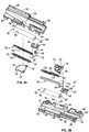
- closing device 10 preferably includes: a base 30, a latching member 40, a rack 50, a biasing member 60, a gear 70 and a damper 80, which are configured to interact via the latching member 40 with a corresponding actuation member 90 that is coupled to or formed into the first drawer slide member 14 at a proximal first end 14'.
- the base 30, the latching member 40, the rack 50 and the gear 70 are preferably constructed of molded plastic and each may be formed of a single piece, as shown, or of an assembly of components.
- the biasing member 60 is shown in the form of a coiled, linear rate extension spring and it, as well as the drawer slide members 14, 16 and 18 are preferably constructed of steel or other suitable materials.
- the base 30 is coupled to the slide member 18.
- the biasing member 60 is coupled at a first end to the slide member 12, via the base 30 including a socket 31 at its proximal end to receive a first end portion 62 of the biasing member 60.
- the base 30 slidably receives the latching member 40 in a slide channel 32.
- the slide channel 32 includes a notch 32' proximate its distal end.
- the base 30 further includes a damper holder 33 that receives the damper 80.
- the base 30 has a planar section 34 in its central region, from which projects a stop wall 35 along an outer edge 36.
- a post 37 extends from the planar section 34 for pivotal coupling to the gear 70, and the stop wall 35 may be used to limit the pivotal movement of the gear 70.
- a slide rail 38 extends along the damper holder 33 for slidable interaction with the rack 50.
- the base 30 is configured to be readily attachable to the third slide member 18 proximate its proximal end 18', to facilitate simple, rapid and secure mounting that also reduces the potential for interference with other components of the assembly.
- the base 30 includes locating members 39 of various configurations and which extend outward to permit the base 30 to be snap fit within the third slide member 18.
- the base 30 may be coupled to the third slide member 18 in numerous different ways, including by use of separate fasteners, adhesives or other interlocking features on the base or slide member.
- the latching member 40 is slidably engaged with the third slide member 18 via its pivotal coupling to the rack 50, because the rack 50 is slidably engaged with the base 30 that is couled to the third slide member 18.
- the latching member 40 has a central body 42 that is slidably received within the slide channel 32.
- a hook portion 44 extends from the distal end of the central body 42 for engagement with the notch 32' when the latching member 40 reaches the distal end of the slide channel 32.
- the latching member 40 also may be selectively coupled to the first drawer slide member 14.
- the latching member 40 includes a pin 46 that is formed as an upstanding projection and which is configured to be coupled to and uncoupled from the actuation member 90, which is shown in the form of a curved slot that is located at the proximal end of the first drawer slide member 14.
- the latching member 40 further includes an aperture 48 in the lower surface of the central body 42 for pivotal coupling to the rack 50. It will be appreciated that these structures could be reversed with respect to the placement of the pin and curved slot on opposite members.
- the rack 50 is engagable with the gear 70, as the rack 50 includes a flat body 52 from which is extended a linear, elongated toothed section 54 for toothed engagement with the gear 70.
- the rack 50 also includes an upstanding post 56 that is received by the aperture 48 in the latching member 40 to affect the aforementioned pivotal coupling of these two components.
- an upstanding hub 58 for coupling of the damper 80 to the rack 50, as will be described further herein.
- the biasing member 60 is illustrated as a coil, linear rate extension spring, although it will be appreciated that other biasing members and configurations may be employed.
- the biasing member 60 has a first end portion 62 coupled to the base 30 via a narrowed section for coupling to the base 30 by insertion into the socket 31, and a second end portion 64 in the form of a loop coupled to the gear 70. Selecting a proper length for the biasing member 60 will keep the latching member 40 at the proximal end of its travel when a drawer is in the closed position, and will help avoid contact with other components and the resultant noise associated with such contact.
- the gear 70 is configured to be relatively flat and sector-shaped, having an arcuate toothed section 72 for engagement with the elongated toothed section 54 of the rack 50.
- the gear 70 includes an aperture 74 for pivotal coupling to the post 37 on the planar section 34 of the base 30.
- the gear 70 also includes a tab 76 for coupling to the loop of the second end portion 64 of the biasing member 60.
- the damper 80 has an outer housing 82 that is received by the base 30 in the damper holder 33.
- An actuating rod 84 is extendable from the distal end of the damper 80 and is coupled to the rack 50 via being coupled to the upstanding hub 58. This coupling between the damper actuating rod 84 and the hub 58 of the rack 50 causes damped linear movement of the latching member 40, as it is coupled to the rack 50.
- the damper 80 preferably dampens only in the closing or retracting direction, but it will be appreciated that the damper 80 could dampen movement in both the retracting and extending directions.
- the first example is shown with the actuation member 90 configured as a curved slot formed in a plastic insert 92 which is coupled by a fastener 94 to the first end 14' of the first drawer slide member 14.
- the slot may be otherwise formed directly into the first slide member 14 or provided via a different piece and that such piece may be coupled to the first slide member 14 by suitable methods of coupling components, such as by use of one or more mechanical fasteners, a press fit, a bonding agent, or the like.
- the actuation member 90 interacts with the pin 46 on the latching member 40, and as noted above the respective structures could be reversed.
- a closing device 10 having a base 30, a latching member 40 that is coupled to a rack 50 that slidably engages the base 30, a gear 70 coupled to the base 30 and engaging the rack 50, a biasing member 60 having a first end 62 coupled to the base 30 and a second end 64 coupled to the gear 70, and wherein the biasing member 60 generates a biasing force as it is lengthened and the engagement of the rack 50 with the gear 70 provides a mechanical advantage that alters the biasing force applied to the latching member 40 in a manner that does not correspond linearly to movement of the latching member 40.
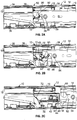
- FIGS. 2A-2C show the motion of the closing device 10 and first drawer slide member 14 in successive positions as they would be moved from a closed position toward an open position.
- the underside of the device is shown in corresponding positions in FIGS. 5A-5C , although it will be understood that the position shown in FIG. 5C would be maintained at any time that the drawer has been moved beyond a point at which the latching member 40 would be engaged with the actuation member 90.
- the latching member 40 pivotally coupled to the rack 50, is shown at the proximal end of its travel in FIGS. 2A , 3A , 3B , 4A and 5A .
- the arcuate toothed section 72 of the gear 70 is engaged with the elongated toothed section 54 of the rack 50 at one end.
- the gear 70 rests against the stop wall 35 along one side of the sector-shaped gear 70, limiting its pivotal travel, while the teeth at one end of the arcuate toothed section 72 of the gear 70 are aligned with the teeth at the distal end of the elongated toothed portion 54 of the rack 50, for meshed movement of the toothed sections 54, 72.
- the biasing member 60 is in a first position in which it has relatively little or no tension, to avoid sagging and to keep the drawer in the closed position, and the latching member 40 is at the proximal end of its travel within the slide channel 32.
- the damper rod 84 is in its retracted position within the damper 80 while coupled to the hub 58 of the rack 50.
- FIGS. 2B and 5B illustrate a position of the first drawer slide member 14 early in its movement toward an open position or late in its movement toward the closed position.
- the pin 46 on the latching member 40 is forced by the wall of the actuation member 90 to move in the distal direction. In turn, this forces the latching member 40 to move along the slide channel 32, forcing the rack 50 to slide along the slide rail 38.
- the toothed engagement with the gear 70 forces the gear 70 to pivot.
- the pivotal movement of the gear 70 causes the tab 76 to move through an arc about the post 37, moving the loop at the second end portion 64 of the biasing member 60, thereby changing the length of the biasing member 60.
- the gear 70 pivots it provides a mechanical advantage that imparts a change in the ratio of linear movement of the rack 50 to the lengthening of the biasing member 60.
- FIG. 2C actually shows the actuation member 40 in the latched or armed position and the first drawer slide member 14 having moved slightly further toward an open position of the drawer and no longer being under the influence of the closing device 10.
- the movement of the latching member 40 to its armed position also advances the rack 50 and its toothed elongated section 54 along the slide rail 38.
- the engagement of the rack 50 with the arcuate toothed section 72 of the gear 70 causes the gear 70 to pivot to a position against stop wall 35, limiting the pivotal movement of the gear 70.
- the ends of travel may be limited simultaneously or alternatively by the ends of travel of the rack 50 along its slide rail 38 and/or by the travel of the latching member 40 within the slide channel 32.
- the tab 76 on the gear 70 is positioned so that when the hook portion 44 on the latching member 40 reaches the notch 32' and assumes its armed position, the biasing member 60 has not passed the pivotal coupling of the gear 70 to the base 30, or the top-dead-center position, and instead is kept in tension and continues to bias the gear 70 to pivot toward the returned position associated with the closed position of the drawer.
- the pivotal movement of the gear 70 causes the biasing member 60 to be further stretched but at a reduced ratio relative to the linear movement of the rack 50 that is pivotally coupled to the latching member 40.
- the mechanical advantage provided with the disclosed arrangement permits the use of a biasing member 60 having a linear rate spring while effectively reducing the rate of increase in the applied spring force as the first drawer slide member 14 moves the latching member 40 toward the armed position.
- This arrangement results in the closing device 10 having sufficient biasing force to move and keep a drawer closed, while also having a lower ultimate biasing force present at the point of disengagement or reengagement of the drawer with the drawer closing device in comparison to prior art devices where the biasing force continues to increase at the same rate as a closing element moves. As a result, the user experiences a more pleasing transition between a drawer being under the influence of the closing device 10 and being free to move beyond the range of motion of the closing device 10.
- the actuation member 90 at the proximal end 14' of the first drawer slide 14 reengages the pin 46 on the latching member 40 and forces the latching member 40 to pivot about the post 56 on the rack 50, withdrawing the hook portion 44 from the notch 32' at the end of the slide channel 32.
- the tensioned biasing member 60 causes the toothed gear 70 to pivot, in turn causing the toothed rack 50 to slide along the slide rail 38 of the base 30.
- the pivotal coupling of the rack 50 to the latching member 40 results in the latching member 40 and the drawer being pulled to the closed position.
- the proximal end 14' of the first drawer slide member 14 is moved within a selected range of motion proximate the proximal end 18' of the third drawer slide member 18, such as within the last 5,08 cm (2 inches) of travel of the drawer slide 12.
- the curvature in the slot of the actuation member 90 at the end of the first drawer slide member 14 is configured to assist in capturing and releasing the pin 46 on the latching member 40.
- the interaction between the curved slot of the actuation member 90 and the pin 46 controls the pivotal motion of the latching member 40 to force the hook 44 to selectively engage and disengage the notch 32' in the slide channel 32 of the base 30 for latching and unlatching of the latching member 40.
- the pin 46 may be constructed in other suitable forms or shapes, and that with some modification, the pin and slot coupling components may be reversed or incorporated into the drawer slide, drawer and/or cabinet in other suitable ways, or the latching and actuating members may be configured in other forms.
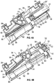
- FIGS. 6A-7B a second example closing device 110 that may be incorporated into a drawer slide or article of furniture having a drawer and cabinet assembly is illustrated.
- the second example is substantially similar to the first example and operates in a similar manner. Therefore, it will be described in a somewhat abbreviated manner, focusing on the main differences relative to the first example and, for ease of reference, using a numbering sequence that corresponds to the first example.
- the second example closing device 110 may be adapted for use in ways similar to those described above in regard to the first example device 10.
- the second example device 10 can be incorporated into a drawer slide as shown in FIGS. 1 and 2A-2C , and which will be referenced herein as if the second example closing device 110 is coupled to the drawer slide 12.
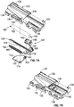
- the closing device 110 preferably includes: a base 130, a latching member 140, a rack 150, a biasing member 160, a gear 170 and a damper 180, which are configured to interact via the latching member 140 with a corresponding actuation member 90 that is coupled to or formed into the first drawer slide member 14 at a proximal first end 14'.
- the base 130, the latching member 140, the rack 150 and the gear 170 are preferably constructed of similar materials to those discussed above in reference to the first example device 10.
- the base 130 would be coupled to the third slide member 18.
- the biasing member 160 is coupled at a first end to the slide member 12, via the base 130 including a socket 131 at its proximal end to receive a first end portion 162 of the biasing member 160.
- the biasing member 160 is shown in the form of a coiled, linear rate extension spring and it is preferably constructed of steel or other suitable materials.
- the base 130 slidably receives the latching member 140 in a slide channel 132.
- the slide channel 132 includes a notch 132' proximate its distal end.
- the base 130 further includes a damper holder 133 that receives the damper 180.
- the damper 180 and corresponding damper holder 133 of the second example 110 are narrower than the damper 80 and damper holder 33 of the first example device 10.
- the base 130 has a planar section 134 in its central region, from which projects a stop wall 135 along an outer edge 136.
- a post 137 extends from the planar section 134 for pivotal coupling to the gear 170, and the stop wall 135 may be used to limit the pivotal movement of the gear 170.
- the gear 170 of the second example device 110 has a larger radius than the gear 70 of the first example device 10.
- a slide rail 138 extends along the damper holder 133 for slidable interaction with the rack 150.
- the base 130 of the second example device 110 is configured to be readily coupled to the third slide member 18 proximate its proximal end 18', to facilitate simple, rapid and secure mounting that also reduces the potential for interference with other components of the assembly.
- the base 130 includes locating members 139 of various configurations and which extend outward to permit the base 130 to be snap fit within the third slide member 18.
- the locating members 139 along the outer edge 136 in the second example device 110 are quite similar to the locating members 39 of the first example device 10, but they are spaced a little differently.
- the base 130 may be coupled to the third slide member 18 in numerous different ways.
- the latching member 140 is slidably engaged with the third slide member 18 via its pivotal coupling to the rack 150, because the rack 150 is slidably engaged with the base 130 that is coupled to the third slide member 18.
- the latching member 140 has a central body 142 that is slidably received within the slide channel 132.
- a hook portion 144 extends from the distal end of the central body 142 for engagement with the notch 132' when the latching member 140 reaches the distal end of the slide channel 132.
- the latching member 140 also may be selectively coupled to the first drawer slide member 14.
- the latching member 140 includes a pin 146 that is formed as an upstanding projection and which is configured to be coupled to and uncoupled from the actuation member 90 located at the proximal end of the first drawer slide member 14.
- the latching member 140 further includes an aperture in the lower surface of the central body 142 for pivotal coupling to the rack 150, which is not shown in FIG. 7A but is similar to aperture 48 shown in FIG. 3B .
- the rack 150 is engagable with the gear 170, as the rack 150 includes a flat body 152 from which is extended a linear, elongated toothed section 154 for toothed engagement with the gear 170.
- the rack 150 also includes an upstanding post 156 that is received by the aperture in the lower surface (not shown) of the latching member 140 to affect the aforementioned pivotal coupling of these two components.
- an upstanding hub 158 for coupling of the damper 180 to the rack 150, as will be described further herein.
- the flat body 152 and hub 158 are shaped a little differently from the flat body 52 and hub 58 of the first example rack 50, but perform the same functions as previously described.
- the biasing member 160 has a first end portion 162 having a narrowed section for coupling to the base 130 via insertion into a socket 131, and a second end portion 164 in the form of a loop for coupling to the gear 170. Selecting a proper length for the biasing member 160 will keep the latching member 140 at the proximal end of its travel when a drawer is in the closed position, and will help avoid contact with other components and the resultant noise associated with such contact.
- the gear 170 having a slightly larger radius still is configured to be relatively flat and sector-shaped, having an arcuate toothed section 172 for engagement with the elongated toothed section 154 of the rack 150.
- the gear 170 includes an aperture 174 for pivotal coupling to the post 137 on the planar section 134 of the base 130.
- the gear 170 also includes a tab 176 for coupling to the loop of the second end portion 164 of the biasing member 160. It will be appreciated that the mechanical advantage obtained by using a gear and rack can be selected as desired.
- the larger gear 170 of the second example closing device 110 results in a different extension ratio between the movement of the latching member 140 and the lengthening of the biasing member 160, yielding approximately a 15 percent increase in latching member travel relative to spring deflection when compared to the components in the first example closing device 10.
- the damper 180 has an outer housing 182 that is received by the base 130 in the damper holder 133.
- An actuating rod 184 is extendable from the distal end of the damper 180 and is coupled to the rack 150 via an upstanding hub 158. This coupling between the damper actuating rod 184 and the hub 158 of the rack 150 causes damped linear movement of the latching member 140 because it is coupled to the rack 150.
- the damper 180 preferably dampens only in the closing or retracting direction, but it will be appreciated that the damper 180 could dampen movement in both the retracting and extending directions.
- the second example device 110 is shown with the same drawer slide components having the actuation member 90 configured as a curved slot formed in a plastic insert 92 which is coupled by a fastener 94 to the first end 14' of the first drawer slide member 14.
- the actuation member 90 interacts with the pin 146 on the latching member 140.
- the drawer closing device 110 is employed to control the final closing motion of the drawer.
- the motion of the second closing device 110 is similar to that shown and described with respect to the first example device, in FIGS. 2A-2C and in FIGS. 5A-5C .
- the latching member 140 pivotally coupled to the rack 150, is shown at the proximal end of its travel in FIGS. 6A and 7A .
- the arcuate toothed section 172 of the gear 170 is engaged with the elongated toothed section 154 of the rack 150 at one end.
- the gear 170 rests against the stop wall 135 along one side of the sector-shaped gear 170, limiting its pivotal travel, while the teeth at one end of the arcuate toothed section 172 of the gear 170 are aligned with the teeth at the distal end of the elongated toothed portion 154 of the rack 150, for meshed movement of the toothed sections 154, 172.
- the biasing member 160 is in a first position in which it has relatively little or no tension, to avoid sagging and to keep the drawer in the closed position, and the latching member 140 is at the proximal end of its travel within the slide channel 132.
- the damper rod 184 is in its retracted position within the damper 180 while coupled to the hub 158 of the rack 150.
- FIG. 6B illustrates a position of the second example device in which the first drawer slide member 14 has been moved toward an open position and has disengaged from the latching member 140.
- the pin 146 on the latching member 140 has been forced by the wall of the actuation member 90 to move in the distal direction.
- the toothed engagement with the gear 170 forced the gear 170 to pivot.
- the pivotal movement of the gear 170 caused the tab 176 to move through an arc about the post 137, moving the loop at the second end portion 164 of the biasing member 160, thereby changing the length of the biasing member 160.
- the gear 170 pivoted it provided a mechanical advantage that imparted a change in the ratio of linear movement of the rack 150 to the lengthening of the biasing member 160.
- FIG. 6B shows the actuation member 140 in the latched or armed position as would occur once the first drawer slide member 14 has moved slightly further toward an open position of the drawer and the actuation member 140 is no longer being under the influence of the drawer closing device 110.
- the movement of the latching member 140 to its armed position also advances the rack 150 and its toothed elongated section 154 along the slide rail 138.
- the engagement of the rack 150 with the arcuate toothed section 172 of the gear 170 causes the gear 170 to pivot to a position against stop wall 135, limiting the pivotal movement of the gear 170.
- the ends of travel may be limited simultaneously or alternatively by the ends of travel of the rack 150 along its slide rail 138 and/or by the travel of the latching member 140 within the slide channel 132.
- the tab 176 on the gear 170 is positioned so that when the hook portion 144 on the latching member 140 reaches the notch 132' and assumes its armed position, the biasing member 160 has not passed the pivotal coupling of the gear 170 to the base 130, or the top-dead-center position, and instead is kept in tension and continues to bias the gear 170 to pivot toward the returned position associated with the closed position of the drawer.
- the pivotal movement of the gear 170 causes the biasing member 160 to be further stretched but at a reduced ratio relative to the linear movement of the rack 150 that is pivotally coupled to the latching member 140.
- the mechanical advantage provided with the disclosed arrangement permits the use of a biasing member 160 having a linear rate spring while effectively reducing the rate of increase in the applied spring force as the first drawer slide member 14 moves the latching member 140 toward the armed position.
- This arrangement results in the closing device 110 having sufficient biasing force to move and keep a drawer closed, while also having a lower ultimate biasing force present at the point of disengagement or reengagement of the drawer with the drawer closing device in comparison to prior art devices where the biasing force continues to increase at the same rate as a closing element moves. As a result, the user experiences a more pleasing transition between a drawer being under the influence of the closing device 110 and being free to move beyond the range of motion of the closing device 110.
- the actuation member 90 at the proximal end 14' of the first drawer slide 14 reengages the pin 146 on the latching member 140 and forces the latching member 140 to pivot about the post 156 on the rack 150, withdrawing the hook portion 144 from the notch 132' at the end of the slide channel 132.
- the tensioned biasing member 160 causes the toothed gear 170 to pivot, in turn causing the toothed rack 150 to slide along the slide rail 138 of the base 130.
- the pivotal coupling of the rack 150 to the latching member 140 results in the latching member 140 and the drawer being pulled to the closed position.
- the proximal end 14' of the first drawer slide member 14 is moved within a selected range of motion proximate the proximal end 18' of the third drawer slide member 18, such as within the last 5,08cm (2 inches) of travel of the drawer slide 12.
- the curvature in the slot of the actuation member 90 at the end of the first drawer slide member 14 is configured to assist in capturing and releasing the pin 146 on the latching member 140.
- the interaction between the curved slot of the actuation member 90 and the pin 146 controls the pivotal motion of the latching member 140 to force the hook 144 to selectively engage and disengage the notch 132' in the slide channel 132 of the base 130 for latching and unlatching of the latching member 140.
- the pin 146 may be constructed in other suitable forms or shapes, and that with some modification, the pin and slot coupling components may be reversed or incorporated into the drawer slide, drawer and/or cabinet in other suitable ways, or the latching and actuating members may be configured in other forms.
- a drawer closing device in accordance with the present disclosure may be provided in various configurations. Any variety of suitable materials of construction, configurations, shapes and sizes for the components and methods of coupling the components may be utilized to meet the particular needs and requirements of an end user. It will be apparent to those skilled in the art that various modifications can be made in the design and construction of such a drawer closing device, whether or not a damper is employed, without departing from the scope of the present disclosure, and that the claims are not limited to the preferred embodiment illustrated.
Landscapes
- Engineering & Computer Science (AREA)
- Mechanical Engineering (AREA)
- Drawers Of Furniture (AREA)
Claims (10)
- Verschlussvorrichtung (10, 110) für Schubladenführungen, umfassend:eine Basis (30, 130);ein Einrastelement (40, 140), das mit einer Zahnstange (50, 150) gekoppelt ist, die verschiebbar in Eingriff ist mit der Basis (30);ein Antriebsorgan (70, 170), das mit der Basis (30, 130) gekoppelt ist und mit der Zahnstange (50, 150) in Eingriff steht;ein Vorspannelement (60, 160), dessen erstes Ende (62, 162) mit der Basis (30, 130) gekoppelt ist und dessen zweites Ende (64, 164) mit dem Antriebsorgan (70, 170) gekoppelt ist; undwobei die Basis (30, 130) einen Führungskanal (32, 132) umfasst und das Einrastelement (40, 140) verschiebbar in Eingriff steht mit dem Führungskanal (32, 132) und wobei das Einrastelement (40, 140) einen Greiferteil (44, 144) aufweist und die Basis (30, 130) eine Aussparung (32', 132') aufweist, die zur Aufnahme des Greiferteils (44, 144) ausgestaltet ist,wobei das Vorspannelement (60, 160) bei ihrer Ausdehnung eine Vorspannkraft erzeugt und der Eingriff von Zahnstange (50, 150) und Antriebsorgan (70, 170) eine mechanische Kraftverstärkung vorsieht, welche die auf das Einrastelement (40, 140) ausgeübte Vorspannkraft in einer Weise ändert, welche linear nicht der Bewegung des Einrastelements (40, 140) entspricht.
- Verschlussvorrichtung (10, 110) nach Anspruch 1, wobei eine lineare Bewegung des Einrastelements (40, 140) relativ zu der Basis (30, 130) um eine vorbestimmte Distanz bewirkt, dass sich das zweite Ende (64, 164) des Vorspannelements (60, 160) relativ zu dem ersten Ende (62, 162) des Vorspannelements (60, 160) um eine Distanz bewegt, die kleiner ist als die vorbestimmte Distanz, um die sich das Einrastelement (40, 140) bewegt.
- Verschlussvorrichtung (10, 110) nach Anspruch 1, wobei das Antriebsorgan (70, 170) einen gebogenen, gezahnten Abschnitt (72, 172) aufweist und die Zahnstange (50, 150) einen länglichen, gezahnten Abschnitt (54, 154) aufweist, der in Eingriff steht mit dem Antriebsorgan (70, 170).
- Verschlussvorrichtung (10, 110) nach Anspruch 1, wobei das Antriebsorgan (70, 170) sektorförmig ist.
- Verschlussvorrichtung (10, 110) nach Anspruch 1, wobei das Antriebsorgan (70, 170) drehbar mit der Basis (30, 130) gekoppelt ist.
- Verschlussvorrichtung (10, 110) nach Anspruch 5, wobei eine Bewegung des Antriebsorgans (70, 170) und der Kopplung des zweiten Endes des Vorspannelements (60, 160) mit dem Antriebsorgan (70, 170) derart begrenzt ist, dass das Vorspannelement (60, 160) an einem Vorbeigelangen an der drehbaren Kopplung des Antriebsorgans (70, 170) mit der Basis (30, 130) gehindert ist.
- Verschlussvorrichtung (10, 110) nach Anspruch 1, wobei das Vorspannelement (60, 160) die Form einer Schneckenfeder hat.
- Verschlussvorrichtung (10, 110) nach Anspruch 1, ferner umfassend einen Dämpfer (80, 180), der die Bewegung des Einrastelements (40, 140) in zumindest eine Richtung dämpft.
- Verschlussvorrichtung (10, 110) nach Anspruch 8, wobei der Dämpfer (80, 180) ein Gehäuse (82, 182) hat, das mit der Basis (30, 130) gekoppelt ist.
- Verschlussvorrichtung (10, 110) nach Anspruch 8, wobei der Dämpfer (80, 180) eine Stange (84, 184) hat, die mit der Zahnstange gekoppelt ist.
Applications Claiming Priority (3)
| Application Number | Priority Date | Filing Date | Title |
|---|---|---|---|
| US25792709P | 2009-11-04 | 2009-11-04 | |
| US12/914,519 US8205951B2 (en) | 2009-11-04 | 2010-10-28 | Closing device for drawers |
| PCT/US2010/055124 WO2011056792A1 (en) | 2009-11-04 | 2010-11-02 | Closing device for drawers |
Publications (3)
| Publication Number | Publication Date |
|---|---|
| EP2496115A1 EP2496115A1 (de) | 2012-09-12 |
| EP2496115A4 EP2496115A4 (de) | 2014-07-09 |
| EP2496115B1 true EP2496115B1 (de) | 2018-06-13 |
Family
ID=43924645
Family Applications (1)
| Application Number | Title | Priority Date | Filing Date |
|---|---|---|---|
| EP10828978.6A Active EP2496115B1 (de) | 2009-11-04 | 2010-11-02 | Verschlussvorrichtung für schubladen |
Country Status (7)
| Country | Link |
|---|---|
| US (1) | US8205951B2 (de) |
| EP (1) | EP2496115B1 (de) |
| JP (1) | JP5591344B2 (de) |
| AU (1) | AU2010315324B2 (de) |
| CA (1) | CA2780009C (de) |
| TW (1) | TWI548365B (de) |
| WO (1) | WO2011056792A1 (de) |
Families Citing this family (47)
| Publication number | Priority date | Publication date | Assignee | Title |
|---|---|---|---|---|
| CN102112777B (zh) * | 2008-08-07 | 2014-12-03 | 伊利诺斯工具制品有限公司 | 粘滞带阻尼器组件 |
| EP2424404B1 (de) | 2009-04-27 | 2016-09-21 | Accuride International Inc. | Gleit- und sperrmechanismus für schublade |
| AT509414B1 (de) * | 2010-02-03 | 2013-04-15 | Blum Gmbh Julius | Kupplungsvorrichtung mit seitenverstellung für eine schublade |
| JP2011196015A (ja) * | 2010-03-17 | 2011-10-06 | Nifco Inc | 摺動補助装置 |
| JP5433466B2 (ja) * | 2010-03-17 | 2014-03-05 | 株式会社ニフコ | 摺動補助装置 |
| EP2372064A1 (de) * | 2010-04-01 | 2011-10-05 | Elfa International AB | Schiebetüranordnung |
| AT509923B1 (de) * | 2010-06-01 | 2013-12-15 | Blum Gmbh Julius | Einzugsvorrichtung zum einziehen eines bewegbar gelagerten möbelteiles |
| AT512306B1 (de) | 2012-01-25 | 2013-07-15 | Fulterer Gmbh | Vorrichtung zur dämpfung der bewegung eines beweglich gelagerten bauteils |
| AT512300B1 (de) | 2012-01-25 | 2013-07-15 | Fulterer Gmbh | Vorrichtung zur dämpfung der bewegung eines beweglich gelagerten bauteils |
| EP2807320B1 (de) | 2012-01-25 | 2018-02-21 | Fulterer AG & Co KG | Ausziehvorrichtung für mindestens zwei ausziehbare möbelteile |
| AT512415B1 (de) | 2012-03-20 | 2013-08-15 | Fulterer Gmbh | Zuziehvorrichtung für ein beweglich gelagertes Möbelteil |
| CN104470403B (zh) | 2012-07-18 | 2017-06-20 | 雅固拉国际有限公司 | 抽屉滑轨及电致动式锁定机构 |
| ES2474290B1 (es) * | 2013-01-08 | 2015-01-02 | Industrias Auxiliares, S.A. (Indaux) | Dispositivo de autocierre para partes móviles correderas |
| US9763350B2 (en) | 2013-01-23 | 2017-09-12 | Seagate Technology Llc | High density data storage system with improved storage device access |
| US9681576B2 (en) | 2013-01-23 | 2017-06-13 | Seagate Technology Llc | Shock dampening drawer slide |
| US9001514B2 (en) | 2013-01-23 | 2015-04-07 | Dot Hill Systems Corporation | Safe rackmountable storage enclosure |
| US9456515B2 (en) | 2013-01-23 | 2016-09-27 | Seagate Technology Llc | Storage enclosure with independent storage device drawers |
| US9098233B2 (en) | 2013-01-23 | 2015-08-04 | Dot Hill Systems Corporation | Storage device carrier for high density storage system |
| US9198322B2 (en) | 2013-01-23 | 2015-11-24 | Dot Hill Systems Corporation | Compliant drawer latch assembly |
| US9763518B2 (en) * | 2014-08-29 | 2017-09-19 | Cisco Technology, Inc. | Systems and methods for damping a storage system |
| US9364089B1 (en) * | 2014-12-01 | 2016-06-14 | King Slide Works Co., Ltd. | Self-closing slide rail assembly with deceleration mechanism |
| US9853873B2 (en) | 2015-01-10 | 2017-12-26 | Cisco Technology, Inc. | Diagnosis and throughput measurement of fibre channel ports in a storage area network environment |
| US10378245B2 (en) * | 2015-01-16 | 2019-08-13 | Accuride International Inc. | Electro-mechanical latching/locking with integrated touch/push activation |
| US9900250B2 (en) | 2015-03-26 | 2018-02-20 | Cisco Technology, Inc. | Scalable handling of BGP route information in VXLAN with EVPN control plane |
| US10222986B2 (en) | 2015-05-15 | 2019-03-05 | Cisco Technology, Inc. | Tenant-level sharding of disks with tenant-specific storage modules to enable policies per tenant in a distributed storage system |
| US11588783B2 (en) | 2015-06-10 | 2023-02-21 | Cisco Technology, Inc. | Techniques for implementing IPV6-based distributed storage space |
| US10778765B2 (en) | 2015-07-15 | 2020-09-15 | Cisco Technology, Inc. | Bid/ask protocol in scale-out NVMe storage |
| US9892075B2 (en) | 2015-12-10 | 2018-02-13 | Cisco Technology, Inc. | Policy driven storage in a microserver computing environment |
| US10140172B2 (en) | 2016-05-18 | 2018-11-27 | Cisco Technology, Inc. | Network-aware storage repairs |
| US20170351639A1 (en) | 2016-06-06 | 2017-12-07 | Cisco Technology, Inc. | Remote memory access using memory mapped addressing among multiple compute nodes |
| US10664169B2 (en) | 2016-06-24 | 2020-05-26 | Cisco Technology, Inc. | Performance of object storage system by reconfiguring storage devices based on latency that includes identifying a number of fragments that has a particular storage device as its primary storage device and another number of fragments that has said particular storage device as its replica storage device |
| DE102016214896A1 (de) * | 2016-08-10 | 2018-02-15 | Schock Metallwerk Gmbh | Auszugführung |
| US11563695B2 (en) | 2016-08-29 | 2023-01-24 | Cisco Technology, Inc. | Queue protection using a shared global memory reserve |
| US10545914B2 (en) | 2017-01-17 | 2020-01-28 | Cisco Technology, Inc. | Distributed object storage |
| US10243823B1 (en) | 2017-02-24 | 2019-03-26 | Cisco Technology, Inc. | Techniques for using frame deep loopback capabilities for extended link diagnostics in fibre channel storage area networks |
| US10713203B2 (en) | 2017-02-28 | 2020-07-14 | Cisco Technology, Inc. | Dynamic partition of PCIe disk arrays based on software configuration / policy distribution |
| US10254991B2 (en) | 2017-03-06 | 2019-04-09 | Cisco Technology, Inc. | Storage area network based extended I/O metrics computation for deep insight into application performance |
| US10292494B1 (en) * | 2017-07-03 | 2019-05-21 | Nan Jeun International Co., Ltd. | Slide rail self-return mechanism |
| US10303534B2 (en) | 2017-07-20 | 2019-05-28 | Cisco Technology, Inc. | System and method for self-healing of application centric infrastructure fabric memory |
| US10404596B2 (en) | 2017-10-03 | 2019-09-03 | Cisco Technology, Inc. | Dynamic route profile storage in a hardware trie routing table |
| US10942666B2 (en) | 2017-10-13 | 2021-03-09 | Cisco Technology, Inc. | Using network device replication in distributed storage clusters |
| WO2020246974A1 (en) * | 2019-06-05 | 2020-12-10 | Knape & Vogt Manufacturing Company | Closing device for drawers |
| US11503909B2 (en) * | 2020-06-11 | 2022-11-22 | Cis Global Llc | Self closing drawer assembly with dual-cam closing mechanism |
| US12514366B2 (en) | 2023-09-01 | 2026-01-06 | Haier Us Appliance Solutions, Inc. | Mount assembly for a soft close mechanism of a slide assembly |
| US12564305B2 (en) | 2023-10-17 | 2026-03-03 | Haier Us Appliance Solutions, Inc. | Trigger assembly for a slide assembly of a dishwashing appliance |
| US12599228B2 (en) | 2023-10-17 | 2026-04-14 | Haier Us Appliance Solutions, Inc. | Locating slot for a trigger support arm of a slide assembly |
| US12599283B2 (en) | 2023-11-03 | 2026-04-14 | Haier Us Appliance Solutions, Inc. | Universal trigger assembly for a slide assembly |
Family Cites Families (22)
| Publication number | Priority date | Publication date | Assignee | Title |
|---|---|---|---|---|
| AT394802B (de) | 1988-12-23 | 1992-06-25 | Blum Gmbh Julius | Schliessvorrichtung fuer schubladen |
| DE9013161U1 (de) | 1990-09-17 | 1990-11-22 | Paul Hettich GmbH & Co, 4983 Kirchlengern | Vorrichtung zum Halten eines in einen Möbelkorpus eingeschobenen Schubkastens |
| AT410504B (de) * | 2000-01-14 | 2003-05-26 | Blum Gmbh Julius | Schliess- und/oder einzugsvorrichtung für bewegbare möbelteile |
| IT250443Y1 (it) * | 2000-09-19 | 2003-09-10 | Salice Arturo Spa | Dispositivo per la chiusura decelerata di parti di mobile scorrevoli |
| US6848759B2 (en) | 2002-04-03 | 2005-02-01 | Illinois Tool Works Inc. | Self-closing slide mechanism with damping |
| US6915716B2 (en) | 2002-04-19 | 2005-07-12 | Illinois Tool Works Inc. | Roller/damper assembly |
| DE10246438A1 (de) | 2002-10-04 | 2004-04-15 | Grass Gmbh | Schubladensystem |
| US6910557B2 (en) | 2003-01-29 | 2005-06-28 | Illinois Tool Works Inc. | Slide damper with spring assist |
| US20040183411A1 (en) * | 2003-03-20 | 2004-09-23 | Boks Michael J. | Self-closing drawer slide |
| US6932511B2 (en) | 2003-04-01 | 2005-08-23 | Illinois Tool Works Inc. | Damped drawer slide mechanism |
| EP1622486A4 (de) | 2003-05-13 | 2009-02-25 | Grass Gmbh | Schubladenschliessmechanismus |
| GB0328262D0 (en) | 2003-12-05 | 2004-01-07 | Titus Int Plc | Improvements in movement controls |
| KR100831102B1 (ko) * | 2004-01-13 | 2008-05-20 | 가부시키가이샤 무라코시 세이코 | 완충장치 |
| JP4459679B2 (ja) * | 2004-03-30 | 2010-04-28 | 株式会社ニフコ | 摺動補助装置 |
| JP4446823B2 (ja) * | 2004-07-21 | 2010-04-07 | 株式会社ニフコ | 摺動補助装置 |
| US7533946B2 (en) | 2005-08-25 | 2009-05-19 | Knape & Vogt Manufacturing Company | Closing device for drawers |
| DE202005018514U1 (de) * | 2005-11-26 | 2007-04-12 | Hettich Paul Gmbh & Co Kg | Schublade |
| US7815267B1 (en) * | 2006-09-15 | 2010-10-19 | Gus Frousiakis | Drawer slide closure apparatus |
| WO2008069248A1 (ja) * | 2006-12-08 | 2008-06-12 | Nifco Inc. | 引き込み機構及び取り付け構造 |
| TWI321996B (en) * | 2007-02-17 | 2010-03-21 | King Slide Works Co Ltd | Slide assembly having an automatic retractable device |
| US8083304B2 (en) * | 2007-07-18 | 2011-12-27 | Accuride International, Inc. | Self closing mechanism for drawer slides |
| US20090033187A1 (en) * | 2007-07-30 | 2009-02-05 | Chin-Hsiang Chung | Auto-returning assembly with mechanical damper |
-
2010
- 2010-10-28 US US12/914,519 patent/US8205951B2/en active Active
- 2010-11-02 EP EP10828978.6A patent/EP2496115B1/de active Active
- 2010-11-02 AU AU2010315324A patent/AU2010315324B2/en not_active Ceased
- 2010-11-02 WO PCT/US2010/055124 patent/WO2011056792A1/en not_active Ceased
- 2010-11-02 CA CA2780009A patent/CA2780009C/en not_active Expired - Fee Related
- 2010-11-02 JP JP2012537944A patent/JP5591344B2/ja not_active Expired - Fee Related
- 2010-11-03 TW TW099137748A patent/TWI548365B/zh active
Non-Patent Citations (1)
| Title |
|---|
| None * |
Also Published As
| Publication number | Publication date |
|---|---|
| EP2496115A4 (de) | 2014-07-09 |
| US8205951B2 (en) | 2012-06-26 |
| WO2011056792A1 (en) | 2011-05-12 |
| TWI548365B (zh) | 2016-09-11 |
| TW201130448A (en) | 2011-09-16 |
| US20110101839A1 (en) | 2011-05-05 |
| JP5591344B2 (ja) | 2014-09-17 |
| CA2780009A1 (en) | 2011-05-12 |
| EP2496115A1 (de) | 2012-09-12 |
| JP2013509953A (ja) | 2013-03-21 |
| AU2010315324A1 (en) | 2012-05-24 |
| CA2780009C (en) | 2014-08-12 |
| AU2010315324B2 (en) | 2014-06-05 |
Similar Documents
| Publication | Publication Date | Title |
|---|---|---|
| EP2496115B1 (de) | Verschlussvorrichtung für schubladen | |
| US8496306B2 (en) | Opening mechanism of slide assembly | |
| US6848759B2 (en) | Self-closing slide mechanism with damping | |
| US6435636B1 (en) | Drawer slide cushion end stop bumper construction | |
| US7533946B2 (en) | Closing device for drawers | |
| US7537296B2 (en) | Dampened movement mechanism and slide incorporating the same | |
| US8172345B2 (en) | Self-moving device for movable furniture parts | |
| US7802856B2 (en) | Drawer slide with push-latch device | |
| US8277002B2 (en) | Self-closing slide assembly with dampening mechanism | |
| US20030001472A1 (en) | Self-closing slide | |
| AU2011281655B2 (en) | Ejector unit and push device | |
| JP7162588B2 (ja) | 引き出し機構のための後退デバイス | |
| EP2201863B1 (de) | Selbstbewegliche Vorrichtung für bewegliche Möbelteile | |
| CN103763987B (zh) | 用于可移动家具部件的打开和闭合装置 | |
| EP2532272B1 (de) | Öffnungsmechanismus einer Schiebeanordnung | |
| US11864651B2 (en) | Closing device for drawers | |
| CA2699232C (en) | Self-moving device for movable furniture parts |
Legal Events
| Date | Code | Title | Description |
|---|---|---|---|
| PUAI | Public reference made under article 153(3) epc to a published international application that has entered the european phase |
Free format text: ORIGINAL CODE: 0009012 |
|
| 17P | Request for examination filed |
Effective date: 20120501 |
|
| AK | Designated contracting states |
Kind code of ref document: A1 Designated state(s): AL AT BE BG CH CY CZ DE DK EE ES FI FR GB GR HR HU IE IS IT LI LT LU LV MC MK MT NL NO PL PT RO RS SE SI SK SM TR |
|
| AX | Request for extension of the european patent |
Extension state: BA ME |
|
| A4 | Supplementary search report drawn up and despatched |
Effective date: 20140610 |
|
| RIC1 | Information provided on ipc code assigned before grant |
Ipc: A47B 88/04 20060101AFI20140603BHEP |
|
| 17Q | First examination report despatched |
Effective date: 20160609 |
|
| REG | Reference to a national code |
Ref country code: DE Ref legal event code: R079 Ref document number: 602010051331 Country of ref document: DE Free format text: PREVIOUS MAIN CLASS: A47B0088040000 Ipc: A47B0088467000 |
|
| GRAP | Despatch of communication of intention to grant a patent |
Free format text: ORIGINAL CODE: EPIDOSNIGR1 |
|
| RIC1 | Information provided on ipc code assigned before grant |
Ipc: A47B 88/467 20170101AFI20180112BHEP |
|
| INTG | Intention to grant announced |
Effective date: 20180202 |
|
| RIN1 | Information on inventor provided before grant (corrected) |
Inventor name: BOKS, MICHAEL J. |
|
| GRAS | Grant fee paid |
Free format text: ORIGINAL CODE: EPIDOSNIGR3 |
|
| GRAA | (expected) grant |
Free format text: ORIGINAL CODE: 0009210 |
|
| AK | Designated contracting states |
Kind code of ref document: B1 Designated state(s): AL AT BE BG CH CY CZ DE DK EE ES FI FR GB GR HR HU IE IS IT LI LT LU LV MC MK MT NL NO PL PT RO RS SE SI SK SM TR |
|
| AX | Request for extension of the european patent |
Extension state: BA ME |
|
| REG | Reference to a national code |
Ref country code: GB Ref legal event code: FG4D |
|
| REG | Reference to a national code |
Ref country code: CH Ref legal event code: EP Ref country code: AT Ref legal event code: REF Ref document number: 1007572 Country of ref document: AT Kind code of ref document: T Effective date: 20180615 |
|
| REG | Reference to a national code |
Ref country code: IE Ref legal event code: FG4D |
|
| REG | Reference to a national code |
Ref country code: DE Ref legal event code: R096 Ref document number: 602010051331 Country of ref document: DE |
|
| REG | Reference to a national code |
Ref country code: NL Ref legal event code: FP |
|
| REG | Reference to a national code |
Ref country code: LT Ref legal event code: MG4D |
|
| PG25 | Lapsed in a contracting state [announced via postgrant information from national office to epo] |
Ref country code: BG Free format text: LAPSE BECAUSE OF FAILURE TO SUBMIT A TRANSLATION OF THE DESCRIPTION OR TO PAY THE FEE WITHIN THE PRESCRIBED TIME-LIMIT Effective date: 20180913 Ref country code: FI Free format text: LAPSE BECAUSE OF FAILURE TO SUBMIT A TRANSLATION OF THE DESCRIPTION OR TO PAY THE FEE WITHIN THE PRESCRIBED TIME-LIMIT Effective date: 20180613 Ref country code: LT Free format text: LAPSE BECAUSE OF FAILURE TO SUBMIT A TRANSLATION OF THE DESCRIPTION OR TO PAY THE FEE WITHIN THE PRESCRIBED TIME-LIMIT Effective date: 20180613 Ref country code: CY Free format text: LAPSE BECAUSE OF FAILURE TO SUBMIT A TRANSLATION OF THE DESCRIPTION OR TO PAY THE FEE WITHIN THE PRESCRIBED TIME-LIMIT Effective date: 20180613 Ref country code: SE Free format text: LAPSE BECAUSE OF FAILURE TO SUBMIT A TRANSLATION OF THE DESCRIPTION OR TO PAY THE FEE WITHIN THE PRESCRIBED TIME-LIMIT Effective date: 20180613 Ref country code: NO Free format text: LAPSE BECAUSE OF FAILURE TO SUBMIT A TRANSLATION OF THE DESCRIPTION OR TO PAY THE FEE WITHIN THE PRESCRIBED TIME-LIMIT Effective date: 20180913 Ref country code: ES Free format text: LAPSE BECAUSE OF FAILURE TO SUBMIT A TRANSLATION OF THE DESCRIPTION OR TO PAY THE FEE WITHIN THE PRESCRIBED TIME-LIMIT Effective date: 20180613 |
|
| PG25 | Lapsed in a contracting state [announced via postgrant information from national office to epo] |
Ref country code: RS Free format text: LAPSE BECAUSE OF FAILURE TO SUBMIT A TRANSLATION OF THE DESCRIPTION OR TO PAY THE FEE WITHIN THE PRESCRIBED TIME-LIMIT Effective date: 20180613 Ref country code: LV Free format text: LAPSE BECAUSE OF FAILURE TO SUBMIT A TRANSLATION OF THE DESCRIPTION OR TO PAY THE FEE WITHIN THE PRESCRIBED TIME-LIMIT Effective date: 20180613 Ref country code: GR Free format text: LAPSE BECAUSE OF FAILURE TO SUBMIT A TRANSLATION OF THE DESCRIPTION OR TO PAY THE FEE WITHIN THE PRESCRIBED TIME-LIMIT Effective date: 20180914 Ref country code: HR Free format text: LAPSE BECAUSE OF FAILURE TO SUBMIT A TRANSLATION OF THE DESCRIPTION OR TO PAY THE FEE WITHIN THE PRESCRIBED TIME-LIMIT Effective date: 20180613 |
|
| REG | Reference to a national code |
Ref country code: AT Ref legal event code: MK05 Ref document number: 1007572 Country of ref document: AT Kind code of ref document: T Effective date: 20180613 |
|
| PG25 | Lapsed in a contracting state [announced via postgrant information from national office to epo] |
Ref country code: SK Free format text: LAPSE BECAUSE OF FAILURE TO SUBMIT A TRANSLATION OF THE DESCRIPTION OR TO PAY THE FEE WITHIN THE PRESCRIBED TIME-LIMIT Effective date: 20180613 Ref country code: RO Free format text: LAPSE BECAUSE OF FAILURE TO SUBMIT A TRANSLATION OF THE DESCRIPTION OR TO PAY THE FEE WITHIN THE PRESCRIBED TIME-LIMIT Effective date: 20180613 Ref country code: PL Free format text: LAPSE BECAUSE OF FAILURE TO SUBMIT A TRANSLATION OF THE DESCRIPTION OR TO PAY THE FEE WITHIN THE PRESCRIBED TIME-LIMIT Effective date: 20180613 Ref country code: CZ Free format text: LAPSE BECAUSE OF FAILURE TO SUBMIT A TRANSLATION OF THE DESCRIPTION OR TO PAY THE FEE WITHIN THE PRESCRIBED TIME-LIMIT Effective date: 20180613 Ref country code: IS Free format text: LAPSE BECAUSE OF FAILURE TO SUBMIT A TRANSLATION OF THE DESCRIPTION OR TO PAY THE FEE WITHIN THE PRESCRIBED TIME-LIMIT Effective date: 20181013 Ref country code: AT Free format text: LAPSE BECAUSE OF FAILURE TO SUBMIT A TRANSLATION OF THE DESCRIPTION OR TO PAY THE FEE WITHIN THE PRESCRIBED TIME-LIMIT Effective date: 20180613 Ref country code: EE Free format text: LAPSE BECAUSE OF FAILURE TO SUBMIT A TRANSLATION OF THE DESCRIPTION OR TO PAY THE FEE WITHIN THE PRESCRIBED TIME-LIMIT Effective date: 20180613 |
|
| REG | Reference to a national code |
Ref country code: CH Ref legal event code: PK Free format text: BERICHTIGUNGEN |
|
| RIC2 | Information provided on ipc code assigned after grant |
Ipc: A47B 88/467 20170101AFI20180112BHEP |
|
| PG25 | Lapsed in a contracting state [announced via postgrant information from national office to epo] |
Ref country code: IT Free format text: LAPSE BECAUSE OF FAILURE TO SUBMIT A TRANSLATION OF THE DESCRIPTION OR TO PAY THE FEE WITHIN THE PRESCRIBED TIME-LIMIT Effective date: 20180613 Ref country code: SM Free format text: LAPSE BECAUSE OF FAILURE TO SUBMIT A TRANSLATION OF THE DESCRIPTION OR TO PAY THE FEE WITHIN THE PRESCRIBED TIME-LIMIT Effective date: 20180613 |
|
| REG | Reference to a national code |
Ref country code: DE Ref legal event code: R097 Ref document number: 602010051331 Country of ref document: DE |
|
| PLBE | No opposition filed within time limit |
Free format text: ORIGINAL CODE: 0009261 |
|
| STAA | Information on the status of an ep patent application or granted ep patent |
Free format text: STATUS: NO OPPOSITION FILED WITHIN TIME LIMIT |
|
| 26N | No opposition filed |
Effective date: 20190314 |
|
| PG25 | Lapsed in a contracting state [announced via postgrant information from national office to epo] |
Ref country code: DK Free format text: LAPSE BECAUSE OF FAILURE TO SUBMIT A TRANSLATION OF THE DESCRIPTION OR TO PAY THE FEE WITHIN THE PRESCRIBED TIME-LIMIT Effective date: 20180613 Ref country code: SI Free format text: LAPSE BECAUSE OF FAILURE TO SUBMIT A TRANSLATION OF THE DESCRIPTION OR TO PAY THE FEE WITHIN THE PRESCRIBED TIME-LIMIT Effective date: 20180613 |
|
| REG | Reference to a national code |
Ref country code: CH Ref legal event code: PL |
|
| PG25 | Lapsed in a contracting state [announced via postgrant information from national office to epo] |
Ref country code: MC Free format text: LAPSE BECAUSE OF FAILURE TO SUBMIT A TRANSLATION OF THE DESCRIPTION OR TO PAY THE FEE WITHIN THE PRESCRIBED TIME-LIMIT Effective date: 20180613 Ref country code: LU Free format text: LAPSE BECAUSE OF NON-PAYMENT OF DUE FEES Effective date: 20181102 |
|
| REG | Reference to a national code |
Ref country code: BE Ref legal event code: MM Effective date: 20181130 |
|
| REG | Reference to a national code |
Ref country code: IE Ref legal event code: MM4A |
|
| PG25 | Lapsed in a contracting state [announced via postgrant information from national office to epo] |
Ref country code: LI Free format text: LAPSE BECAUSE OF NON-PAYMENT OF DUE FEES Effective date: 20181130 Ref country code: CH Free format text: LAPSE BECAUSE OF NON-PAYMENT OF DUE FEES Effective date: 20181130 |
|
| PG25 | Lapsed in a contracting state [announced via postgrant information from national office to epo] |
Ref country code: IE Free format text: LAPSE BECAUSE OF NON-PAYMENT OF DUE FEES Effective date: 20181102 |
|
| PG25 | Lapsed in a contracting state [announced via postgrant information from national office to epo] |
Ref country code: AL Free format text: LAPSE BECAUSE OF FAILURE TO SUBMIT A TRANSLATION OF THE DESCRIPTION OR TO PAY THE FEE WITHIN THE PRESCRIBED TIME-LIMIT Effective date: 20180613 Ref country code: BE Free format text: LAPSE BECAUSE OF NON-PAYMENT OF DUE FEES Effective date: 20181130 |
|
| PG25 | Lapsed in a contracting state [announced via postgrant information from national office to epo] |
Ref country code: MT Free format text: LAPSE BECAUSE OF NON-PAYMENT OF DUE FEES Effective date: 20181102 |
|
| PGFP | Annual fee paid to national office [announced via postgrant information from national office to epo] |
Ref country code: DE Payment date: 20191127 Year of fee payment: 10 Ref country code: NL Payment date: 20191126 Year of fee payment: 10 |
|
| PGFP | Annual fee paid to national office [announced via postgrant information from national office to epo] |
Ref country code: FR Payment date: 20191125 Year of fee payment: 10 |
|
| PG25 | Lapsed in a contracting state [announced via postgrant information from national office to epo] |
Ref country code: TR Free format text: LAPSE BECAUSE OF FAILURE TO SUBMIT A TRANSLATION OF THE DESCRIPTION OR TO PAY THE FEE WITHIN THE PRESCRIBED TIME-LIMIT Effective date: 20180613 |
|
| PGFP | Annual fee paid to national office [announced via postgrant information from national office to epo] |
Ref country code: GB Payment date: 20191127 Year of fee payment: 10 |
|
| PG25 | Lapsed in a contracting state [announced via postgrant information from national office to epo] |
Ref country code: PT Free format text: LAPSE BECAUSE OF FAILURE TO SUBMIT A TRANSLATION OF THE DESCRIPTION OR TO PAY THE FEE WITHIN THE PRESCRIBED TIME-LIMIT Effective date: 20180613 |
|
| PG25 | Lapsed in a contracting state [announced via postgrant information from national office to epo] |
Ref country code: HU Free format text: LAPSE BECAUSE OF FAILURE TO SUBMIT A TRANSLATION OF THE DESCRIPTION OR TO PAY THE FEE WITHIN THE PRESCRIBED TIME-LIMIT; INVALID AB INITIO Effective date: 20101102 Ref country code: MK Free format text: LAPSE BECAUSE OF NON-PAYMENT OF DUE FEES Effective date: 20180613 |
|
| REG | Reference to a national code |
Ref country code: DE Ref legal event code: R119 Ref document number: 602010051331 Country of ref document: DE |
|
| REG | Reference to a national code |
Ref country code: NL Ref legal event code: MM Effective date: 20201201 |
|
| GBPC | Gb: european patent ceased through non-payment of renewal fee |
Effective date: 20201102 |
|
| PG25 | Lapsed in a contracting state [announced via postgrant information from national office to epo] |
Ref country code: NL Free format text: LAPSE BECAUSE OF NON-PAYMENT OF DUE FEES Effective date: 20201201 |
|
| PG25 | Lapsed in a contracting state [announced via postgrant information from national office to epo] |
Ref country code: FR Free format text: LAPSE BECAUSE OF NON-PAYMENT OF DUE FEES Effective date: 20201130 |
|
| PG25 | Lapsed in a contracting state [announced via postgrant information from national office to epo] |
Ref country code: GB Free format text: LAPSE BECAUSE OF NON-PAYMENT OF DUE FEES Effective date: 20201102 Ref country code: DE Free format text: LAPSE BECAUSE OF NON-PAYMENT OF DUE FEES Effective date: 20210601 |