EP2496182B1 - Prothèse de valve - Google Patents
Prothèse de valve Download PDFInfo
- Publication number
- EP2496182B1 EP2496182B1 EP10829157.6A EP10829157A EP2496182B1 EP 2496182 B1 EP2496182 B1 EP 2496182B1 EP 10829157 A EP10829157 A EP 10829157A EP 2496182 B1 EP2496182 B1 EP 2496182B1
- Authority
- EP
- European Patent Office
- Prior art keywords
- stent
- prosthesis
- catheter
- flange portion
- valve
- Prior art date
- Legal status (The legal status is an assumption and is not a legal conclusion. Google has not performed a legal analysis and makes no representation as to the accuracy of the status listed.)
- Active
Links
Images




Classifications
-
- A—HUMAN NECESSITIES
- A61—MEDICAL OR VETERINARY SCIENCE; HYGIENE
- A61F—FILTERS IMPLANTABLE INTO BLOOD VESSELS; PROSTHESES; DEVICES PROVIDING PATENCY TO, OR PREVENTING COLLAPSING OF, TUBULAR STRUCTURES OF THE BODY, e.g. STENTS; ORTHOPAEDIC, NURSING OR CONTRACEPTIVE DEVICES; FOMENTATION; TREATMENT OR PROTECTION OF EYES OR EARS; BANDAGES, DRESSINGS OR ABSORBENT PADS; FIRST-AID KITS
- A61F2/00—Filters implantable into blood vessels; Prostheses, i.e. artificial substitutes or replacements for parts of the body; Appliances for connecting them with the body; Devices providing patency to, or preventing collapsing of, tubular structures of the body, e.g. stents
- A61F2/02—Prostheses implantable into the body
- A61F2/24—Heart valves ; Vascular valves, e.g. venous valves; Heart implants, e.g. passive devices for improving the function of the native valve or the heart muscle; Transmyocardial revascularisation [TMR] devices; Valves implantable in the body
- A61F2/2412—Heart valves ; Vascular valves, e.g. venous valves; Heart implants, e.g. passive devices for improving the function of the native valve or the heart muscle; Transmyocardial revascularisation [TMR] devices; Valves implantable in the body with soft flexible valve members, e.g. tissue valves shaped like natural valves
- A61F2/2418—Scaffolds therefor, e.g. support stents
-
- A—HUMAN NECESSITIES
- A61—MEDICAL OR VETERINARY SCIENCE; HYGIENE
- A61F—FILTERS IMPLANTABLE INTO BLOOD VESSELS; PROSTHESES; DEVICES PROVIDING PATENCY TO, OR PREVENTING COLLAPSING OF, TUBULAR STRUCTURES OF THE BODY, e.g. STENTS; ORTHOPAEDIC, NURSING OR CONTRACEPTIVE DEVICES; FOMENTATION; TREATMENT OR PROTECTION OF EYES OR EARS; BANDAGES, DRESSINGS OR ABSORBENT PADS; FIRST-AID KITS
- A61F2/00—Filters implantable into blood vessels; Prostheses, i.e. artificial substitutes or replacements for parts of the body; Appliances for connecting them with the body; Devices providing patency to, or preventing collapsing of, tubular structures of the body, e.g. stents
- A61F2/02—Prostheses implantable into the body
- A61F2/24—Heart valves ; Vascular valves, e.g. venous valves; Heart implants, e.g. passive devices for improving the function of the native valve or the heart muscle; Transmyocardial revascularisation [TMR] devices; Valves implantable in the body
-
- A—HUMAN NECESSITIES
- A61—MEDICAL OR VETERINARY SCIENCE; HYGIENE
- A61F—FILTERS IMPLANTABLE INTO BLOOD VESSELS; PROSTHESES; DEVICES PROVIDING PATENCY TO, OR PREVENTING COLLAPSING OF, TUBULAR STRUCTURES OF THE BODY, e.g. STENTS; ORTHOPAEDIC, NURSING OR CONTRACEPTIVE DEVICES; FOMENTATION; TREATMENT OR PROTECTION OF EYES OR EARS; BANDAGES, DRESSINGS OR ABSORBENT PADS; FIRST-AID KITS
- A61F2/00—Filters implantable into blood vessels; Prostheses, i.e. artificial substitutes or replacements for parts of the body; Appliances for connecting them with the body; Devices providing patency to, or preventing collapsing of, tubular structures of the body, e.g. stents
- A61F2/02—Prostheses implantable into the body
- A61F2/24—Heart valves ; Vascular valves, e.g. venous valves; Heart implants, e.g. passive devices for improving the function of the native valve or the heart muscle; Transmyocardial revascularisation [TMR] devices; Valves implantable in the body
- A61F2/2409—Support rings therefor, e.g. for connecting valves to tissue
-
- A—HUMAN NECESSITIES
- A61—MEDICAL OR VETERINARY SCIENCE; HYGIENE
- A61F—FILTERS IMPLANTABLE INTO BLOOD VESSELS; PROSTHESES; DEVICES PROVIDING PATENCY TO, OR PREVENTING COLLAPSING OF, TUBULAR STRUCTURES OF THE BODY, e.g. STENTS; ORTHOPAEDIC, NURSING OR CONTRACEPTIVE DEVICES; FOMENTATION; TREATMENT OR PROTECTION OF EYES OR EARS; BANDAGES, DRESSINGS OR ABSORBENT PADS; FIRST-AID KITS
- A61F2/00—Filters implantable into blood vessels; Prostheses, i.e. artificial substitutes or replacements for parts of the body; Appliances for connecting them with the body; Devices providing patency to, or preventing collapsing of, tubular structures of the body, e.g. stents
- A61F2/02—Prostheses implantable into the body
- A61F2/24—Heart valves ; Vascular valves, e.g. venous valves; Heart implants, e.g. passive devices for improving the function of the native valve or the heart muscle; Transmyocardial revascularisation [TMR] devices; Valves implantable in the body
- A61F2/2427—Devices for manipulating or deploying heart valves during implantation
- A61F2/2436—Deployment by retracting a sheath
-
- A—HUMAN NECESSITIES
- A61—MEDICAL OR VETERINARY SCIENCE; HYGIENE
- A61F—FILTERS IMPLANTABLE INTO BLOOD VESSELS; PROSTHESES; DEVICES PROVIDING PATENCY TO, OR PREVENTING COLLAPSING OF, TUBULAR STRUCTURES OF THE BODY, e.g. STENTS; ORTHOPAEDIC, NURSING OR CONTRACEPTIVE DEVICES; FOMENTATION; TREATMENT OR PROTECTION OF EYES OR EARS; BANDAGES, DRESSINGS OR ABSORBENT PADS; FIRST-AID KITS
- A61F2210/00—Particular material properties of prostheses classified in groups A61F2/00 - A61F2/26 or A61F2/82 or A61F9/00 or A61F11/00 or subgroups thereof
- A61F2210/0004—Particular material properties of prostheses classified in groups A61F2/00 - A61F2/26 or A61F2/82 or A61F9/00 or A61F11/00 or subgroups thereof bioabsorbable
-
- A—HUMAN NECESSITIES
- A61—MEDICAL OR VETERINARY SCIENCE; HYGIENE
- A61F—FILTERS IMPLANTABLE INTO BLOOD VESSELS; PROSTHESES; DEVICES PROVIDING PATENCY TO, OR PREVENTING COLLAPSING OF, TUBULAR STRUCTURES OF THE BODY, e.g. STENTS; ORTHOPAEDIC, NURSING OR CONTRACEPTIVE DEVICES; FOMENTATION; TREATMENT OR PROTECTION OF EYES OR EARS; BANDAGES, DRESSINGS OR ABSORBENT PADS; FIRST-AID KITS
- A61F2210/00—Particular material properties of prostheses classified in groups A61F2/00 - A61F2/26 or A61F2/82 or A61F9/00 or A61F11/00 or subgroups thereof
- A61F2210/0014—Particular material properties of prostheses classified in groups A61F2/00 - A61F2/26 or A61F2/82 or A61F9/00 or A61F11/00 or subgroups thereof using shape memory or superelastic materials, e.g. nitinol
-
- A—HUMAN NECESSITIES
- A61—MEDICAL OR VETERINARY SCIENCE; HYGIENE
- A61F—FILTERS IMPLANTABLE INTO BLOOD VESSELS; PROSTHESES; DEVICES PROVIDING PATENCY TO, OR PREVENTING COLLAPSING OF, TUBULAR STRUCTURES OF THE BODY, e.g. STENTS; ORTHOPAEDIC, NURSING OR CONTRACEPTIVE DEVICES; FOMENTATION; TREATMENT OR PROTECTION OF EYES OR EARS; BANDAGES, DRESSINGS OR ABSORBENT PADS; FIRST-AID KITS
- A61F2210/00—Particular material properties of prostheses classified in groups A61F2/00 - A61F2/26 or A61F2/82 or A61F9/00 or A61F11/00 or subgroups thereof
- A61F2210/0061—Particular material properties of prostheses classified in groups A61F2/00 - A61F2/26 or A61F2/82 or A61F9/00 or A61F11/00 or subgroups thereof swellable
-
- A—HUMAN NECESSITIES
- A61—MEDICAL OR VETERINARY SCIENCE; HYGIENE
- A61F—FILTERS IMPLANTABLE INTO BLOOD VESSELS; PROSTHESES; DEVICES PROVIDING PATENCY TO, OR PREVENTING COLLAPSING OF, TUBULAR STRUCTURES OF THE BODY, e.g. STENTS; ORTHOPAEDIC, NURSING OR CONTRACEPTIVE DEVICES; FOMENTATION; TREATMENT OR PROTECTION OF EYES OR EARS; BANDAGES, DRESSINGS OR ABSORBENT PADS; FIRST-AID KITS
- A61F2210/00—Particular material properties of prostheses classified in groups A61F2/00 - A61F2/26 or A61F2/82 or A61F9/00 or A61F11/00 or subgroups thereof
- A61F2210/0076—Particular material properties of prostheses classified in groups A61F2/00 - A61F2/26 or A61F2/82 or A61F9/00 or A61F11/00 or subgroups thereof multilayered, e.g. laminated structures
-
- A—HUMAN NECESSITIES
- A61—MEDICAL OR VETERINARY SCIENCE; HYGIENE
- A61F—FILTERS IMPLANTABLE INTO BLOOD VESSELS; PROSTHESES; DEVICES PROVIDING PATENCY TO, OR PREVENTING COLLAPSING OF, TUBULAR STRUCTURES OF THE BODY, e.g. STENTS; ORTHOPAEDIC, NURSING OR CONTRACEPTIVE DEVICES; FOMENTATION; TREATMENT OR PROTECTION OF EYES OR EARS; BANDAGES, DRESSINGS OR ABSORBENT PADS; FIRST-AID KITS
- A61F2220/00—Fixations or connections for prostheses classified in groups A61F2/00 - A61F2/26 or A61F2/82 or A61F9/00 or A61F11/00 or subgroups thereof
- A61F2220/0008—Fixation appliances for connecting prostheses to the body
-
- A—HUMAN NECESSITIES
- A61—MEDICAL OR VETERINARY SCIENCE; HYGIENE
- A61F—FILTERS IMPLANTABLE INTO BLOOD VESSELS; PROSTHESES; DEVICES PROVIDING PATENCY TO, OR PREVENTING COLLAPSING OF, TUBULAR STRUCTURES OF THE BODY, e.g. STENTS; ORTHOPAEDIC, NURSING OR CONTRACEPTIVE DEVICES; FOMENTATION; TREATMENT OR PROTECTION OF EYES OR EARS; BANDAGES, DRESSINGS OR ABSORBENT PADS; FIRST-AID KITS
- A61F2230/00—Geometry of prostheses classified in groups A61F2/00 - A61F2/26 or A61F2/82 or A61F9/00 or A61F11/00 or subgroups thereof
- A61F2230/0002—Two-dimensional shapes, e.g. cross-sections
- A61F2230/0028—Shapes in the form of latin or greek characters
- A61F2230/0054—V-shaped
-
- A—HUMAN NECESSITIES
- A61—MEDICAL OR VETERINARY SCIENCE; HYGIENE
- A61F—FILTERS IMPLANTABLE INTO BLOOD VESSELS; PROSTHESES; DEVICES PROVIDING PATENCY TO, OR PREVENTING COLLAPSING OF, TUBULAR STRUCTURES OF THE BODY, e.g. STENTS; ORTHOPAEDIC, NURSING OR CONTRACEPTIVE DEVICES; FOMENTATION; TREATMENT OR PROTECTION OF EYES OR EARS; BANDAGES, DRESSINGS OR ABSORBENT PADS; FIRST-AID KITS
- A61F2230/00—Geometry of prostheses classified in groups A61F2/00 - A61F2/26 or A61F2/82 or A61F9/00 or A61F11/00 or subgroups thereof
- A61F2230/0002—Two-dimensional shapes, e.g. cross-sections
- A61F2230/0028—Shapes in the form of latin or greek characters
- A61F2230/0058—X-shaped
-
- A—HUMAN NECESSITIES
- A61—MEDICAL OR VETERINARY SCIENCE; HYGIENE
- A61F—FILTERS IMPLANTABLE INTO BLOOD VESSELS; PROSTHESES; DEVICES PROVIDING PATENCY TO, OR PREVENTING COLLAPSING OF, TUBULAR STRUCTURES OF THE BODY, e.g. STENTS; ORTHOPAEDIC, NURSING OR CONTRACEPTIVE DEVICES; FOMENTATION; TREATMENT OR PROTECTION OF EYES OR EARS; BANDAGES, DRESSINGS OR ABSORBENT PADS; FIRST-AID KITS
- A61F2230/00—Geometry of prostheses classified in groups A61F2/00 - A61F2/26 or A61F2/82 or A61F9/00 or A61F11/00 or subgroups thereof
- A61F2230/0063—Three-dimensional shapes
- A61F2230/0073—Quadric-shaped
- A61F2230/0078—Quadric-shaped hyperboloidal
-
- A—HUMAN NECESSITIES
- A61—MEDICAL OR VETERINARY SCIENCE; HYGIENE
- A61F—FILTERS IMPLANTABLE INTO BLOOD VESSELS; PROSTHESES; DEVICES PROVIDING PATENCY TO, OR PREVENTING COLLAPSING OF, TUBULAR STRUCTURES OF THE BODY, e.g. STENTS; ORTHOPAEDIC, NURSING OR CONTRACEPTIVE DEVICES; FOMENTATION; TREATMENT OR PROTECTION OF EYES OR EARS; BANDAGES, DRESSINGS OR ABSORBENT PADS; FIRST-AID KITS
- A61F2250/00—Special features of prostheses classified in groups A61F2/00 - A61F2/26 or A61F2/82 or A61F9/00 or A61F11/00 or subgroups thereof
- A61F2250/0014—Special features of prostheses classified in groups A61F2/00 - A61F2/26 or A61F2/82 or A61F9/00 or A61F11/00 or subgroups thereof having different values of a given property or geometrical feature, e.g. mechanical property or material property, at different locations within the same prosthesis
- A61F2250/003—Special features of prostheses classified in groups A61F2/00 - A61F2/26 or A61F2/82 or A61F9/00 or A61F11/00 or subgroups thereof having different values of a given property or geometrical feature, e.g. mechanical property or material property, at different locations within the same prosthesis differing in adsorbability or resorbability, i.e. in adsorption or resorption time
-
- A—HUMAN NECESSITIES
- A61—MEDICAL OR VETERINARY SCIENCE; HYGIENE
- A61F—FILTERS IMPLANTABLE INTO BLOOD VESSELS; PROSTHESES; DEVICES PROVIDING PATENCY TO, OR PREVENTING COLLAPSING OF, TUBULAR STRUCTURES OF THE BODY, e.g. STENTS; ORTHOPAEDIC, NURSING OR CONTRACEPTIVE DEVICES; FOMENTATION; TREATMENT OR PROTECTION OF EYES OR EARS; BANDAGES, DRESSINGS OR ABSORBENT PADS; FIRST-AID KITS
- A61F2250/00—Special features of prostheses classified in groups A61F2/00 - A61F2/26 or A61F2/82 or A61F9/00 or A61F11/00 or subgroups thereof
- A61F2250/0014—Special features of prostheses classified in groups A61F2/00 - A61F2/26 or A61F2/82 or A61F9/00 or A61F11/00 or subgroups thereof having different values of a given property or geometrical feature, e.g. mechanical property or material property, at different locations within the same prosthesis
- A61F2250/0039—Special features of prostheses classified in groups A61F2/00 - A61F2/26 or A61F2/82 or A61F9/00 or A61F11/00 or subgroups thereof having different values of a given property or geometrical feature, e.g. mechanical property or material property, at different locations within the same prosthesis differing in diameter
-
- A—HUMAN NECESSITIES
- A61—MEDICAL OR VETERINARY SCIENCE; HYGIENE
- A61F—FILTERS IMPLANTABLE INTO BLOOD VESSELS; PROSTHESES; DEVICES PROVIDING PATENCY TO, OR PREVENTING COLLAPSING OF, TUBULAR STRUCTURES OF THE BODY, e.g. STENTS; ORTHOPAEDIC, NURSING OR CONTRACEPTIVE DEVICES; FOMENTATION; TREATMENT OR PROTECTION OF EYES OR EARS; BANDAGES, DRESSINGS OR ABSORBENT PADS; FIRST-AID KITS
- A61F2250/00—Special features of prostheses classified in groups A61F2/00 - A61F2/26 or A61F2/82 or A61F9/00 or A61F11/00 or subgroups thereof
- A61F2250/0058—Additional features; Implant or prostheses properties not otherwise provided for
- A61F2250/0069—Sealing means
Definitions
- the present disclosure relates to anatomical valve replacement devices and methods and systems for replacing a valve and for delivering a stented device.
- the mitral valve is a complex structure whose competence relies on the precise interaction of annulus, leaflets, chordae, papillary muscles and left ventricle (LV). Pathologic changes in any of these structures can lead to valvular insufficiency.
- Myxomatous leaflet/chordal degeneration, and dilated ischemic cardiomyopathy secondary to chronic post infarction ventricular remodeling are among most common mechanisms producing mitral regurgitation (MR). These two disease processes account for about 78% of all cases of MR treated surgically.
- valve must be compatible with acceptable delivery modalities, it must anchor to the valvular ring and seal the anchor point to prevent leaks, and the valve must function normally when in place.
- percutaneous valved stent having the characteristics that are believed to be necessary for successful implantation, stability, and long-term functionality. A design having such characteristics would have profound medical implications both for those newly in need of valve replacement, and among patients that are currently fitted with conventional valve designs.
- WO2009/132187 discloses stented heart valve devices.
- valve prostheses comprising a self-expanding stent comprising an outer surface, an interior surface, a middle region, an upper anchoring flange, and a lower anchoring flange, wherein the stent has an unexpanded and an expanded state; a cuff comprising an absorbent material disposed at least partially circumferentially around the outer surface of the stent, wherein the absorbent material expands by absorption of a fluid to substantially adhere the prosthesis at an implantation site, and wherein the adhering is delayed for a time sufficient to permit positioning of the prosthesis at the implantation site; and a valve comprising at least two leaflets fixedly attached to the interior surface of the stent.
- methods for replacing a damaged or diseased valve in a subject comprising: delivering to an implantation site of the subject a mitral valve prosthesis comprising a self-expanding stent comprising an outer surface, an interior surface, a middle region, an upper anchoring flange, and a lower anchoring flange, wherein the stent has an unexpanded and an expanded state; a cuff comprising an absorbent material disposed at least partially circumferentially around the outer surface of the stent and a valve comprising at least two leaflets fixedly attached to the interior surface of the stent; and expanding the cuff by absorption of a fluid to substantially adhere the prosthesis at an implantation site, wherein the adhering is delayed for a time sufficient to permit positioning of the prosthesis at the implantation site.
- valve prostheses comprising an at least partially self-expanding stent comprising a wire framework defining outer and interior surfaces, and upper and lower anchoring flanges interposed by a middle region, the stent having an unexpanded and an expanded state, and the lower anchoring flange having at least one geometric dimension that is greater than the corresponding dimension of the upper anchoring flange; and a valve comprising at least one leaflet fixedly attached to the interior surface of the stent.
- the present disclosure also includes methods which are not part of the invention for replacing a damaged or diseased valve in a subject comprising: delivering to an implantation site of the subject a valve prosthesis comprising an at least partially self-expanding stent comprising a wire framework defining outer and interior surfaces, and upper and lower anchoring flanges interposed by a middle region, the stent having an unexpanded and an expanded state, and the lower anchoring flange having at least one geometric dimension that is greater than the corresponding dimension of the upper anchoring flange; and a valve comprising at least one leaflet fixedly attached to the interior surface of the stent; and expanding the stent to substantially adhere the prosthesis at the implantation site.
- a valve prosthesis comprising an at least partially self-expanding stent to an implantation site comprising: a catheter comprising a distal end and a proximal end, a guidewire lumen to permit the catheter to be translated along a guidewire, a steering lumen for accommodating a tension cable for steering the catheter, and a dock at the distal end onto which the stent may be loaded.
- the present systems also comprise a retractable compression sleeve for compressing at least a portion of the stent while the stent is loaded onto the dock; a leading tip positioned distal to the dock for leading the catheter during delivery; and, a steering mechanism operably associated with the tension cable for deflecting the leading tip in at least one directional plane.
- kits comprising a system comprising an at least partially self-expanding stent to an implantation site comprising: a catheter comprising a distal end and a proximal end, a guidewire lumen to permit the catheter to be translated along a guidewire, a steering lumen for accommodating a tension cable for steering the catheter, and, a dock at the distal end onto which the stent may be loaded; a retractable compression sleeve for compressing at least a portion of the stent while the stent is loaded onto the dock; a leading tip positioned distal to the dock for leading the catheter during delivery; and, a steering mechanism operably associated with the tension cable for deflecting the leading tip in at least one directional plane; and, at least one valve prosthesis comprising an at least partially self-expanding stent comprising a wire framework defining outer and interior surfaces, and upper and lower anchoring flanges interposed by a middle region, the stent having an unexpande
- the present disclosure also pertains to methods which are not part of the invention for delivering a valve prosthesis comprising an at least partially self-expanding stent to an implantation site comprising: (i) providing a system comprising a catheter comprising a distal end and a proximal end, a guidewire lumen to permit the catheter to be translated along a guidewire, a steering lumen for accommodating a tension cable for steering the catheter, and, a dock at the distal end onto which the stent may be loaded; a retractable compression sleeve for compressing at least a portion of the stent while the stent is loaded onto the dock; a leading tip positioned distal to the dock for leading the catheter during delivery; and, a steering mechanism operably associated with the tension cable for deflecting the leading tip in at least one directional plane; (ii) loading onto the dock the valve prosthesis; (iii) delivering a guidewire to the implantation site; (iv) translating the catheter over the guidewire so that the loaded
- the phrase "about 8" preferably refers to a value of 7.2 to 8.8, inclusive; as another example, the phrase “about 8%” preferably (but not always) refers to a value of 7.2% to 8.8%, inclusive.
- all ranges are inclusive and combinable. For example, when a range of "1 to 5" is recited, the recited range should be construed as including ranges “1 to 4", “1 to 3", “1-2", “1-2 & 4-5", “1-3 & 5", "2-5", and the like.
- a list of alternatives is positively provided, such listing can be interpreted to mean that any of the alternatives may be excluded, e.g., by a negative limitation in the claims.
- a range of "1 to 5" when a range of "1 to 5" is recited, the recited range may be construed as including situations whereby any of 1, 2, 3, 4, or 5 are negatively excluded; thus, a recitation of "1 to 5" may be construed as “1 and 3-5, but not 2", or simply "wherein 2 is not included.”
- any component, element, attribute, or step that is disclosed with respect to one aspect of the present invention may apply to any other aspect of the present invention (any other of the rostheses, systems, kits, and methods, respectively) that is disclosed herein.
- valve replacements are foldable for catheter-based deployment to the site of implantation, include highly effective anchoring mechanisms for secure and enduring precision implantation, employ unique sealing mechanisms that prevents perivalvular leaks, and incorporates an appropriate leaflet system for reliable functioning in situ.
- the following disclosure pertains to a first general embodiment of the present disclosure, which pertains to inventive valve prostheses for replacing a damaged or diseased valve.
- valve prostheses comprising a self-expanding stent comprising an outer surface, an interior surface, a middle region, an upper anchoring flange, and a lower anchoring flange, wherein the stent has an unexpanded and an expanded state; a cuff comprising an absorbent material disposed at least partially circumferentially around the outer surface of the stent, wherein the absorbent material expands by absorption of a fluid to substantially adhere the prosthesis at an implantation site, and wherein the anchoring is delayed for a time sufficient to permit positioning of the prosthesis at the implantation site; and a valve comprising at least two leaflets fixedly attached to the interior surface of the stent.
- the prosthesis is a mitral valve prosthesis.
- the stent may be self-expanding, or may be configured to be forcibly expanded, for example, by a balloon.
- the stent is self-expanding.
- the self-expanding stent preferably comprises a shape-memory or "superelastic" material exhibiting large elastic strains.
- An exemplary material is nitinol, a nickel-titanium alloy. Any other material possessing similar characteristics may also be used in the construction of the self-expanding stent, and more generally, and suitable, biocompatible material may be used to form the stent, whether it is self-expanding or not.
- Exemplary materials include stainless steel, cobalt/chromium alloy, cobalt/chromium/nickel alloy, nickel/chromium alloy, platinum, platinum/iridium alloy, among others.
- the stent may comprise one or more other materials that are themselves not self-expanding but that do not inhibit or otherwise interfere with the ability of the stent to self-expand.
- any biocompatible material may be included to add any other desired structural feature to the stent.
- Exemplary biocompatible materials include stainless steel, tantalum, platinum alloys, niobium alloys, and cobalt alloys, among others. Additionally or alternatively, one or more bioabsorbable materials may be used in forming the stent.
- the stent may be coated with a composition comprising a drug, so that the stent is capable of eluting drug in situ.
- the stent preferably comprises a framework that is formed from the material that allows the stent to be self-expanding, in addition to any other compatible materials as described above.
- the structural framework can be formed from wire using conventional techniques, such as coiling, weaving, braiding, or knitting.
- the wire may be welded or otherwise joined at some or all crossover points, thereby forming a structure that is not hinged.
- the formation of stents is readily appreciated among those skilled in the art and the present disclosure is intended to embrace any suitable technique, including any functionally acceptable stent geometry.
- the stent comprises a middle region having various dimensions, including an unexpanded length, an unexpanded outer circumference, an expanded length, and an expanded outer circumference.
- the unexpanded length is preferably substantially the same as or greater than the expanded length, and the expanded outer circumference is greater than the unexpanded outer circumference.
- the unexpanded outer circumference may be any size that enables the unexpanded stent to be translated through the interior of a catheter.
- the unexpanded outer circumference may be of a size that enables the unexpanded stent to be translated along the interior of a catheter having a diameter of about 1 mm to about 8 mm.
- the expanded length preferably substantially corresponds to the length that is about the same as or longer than that of the annulus between the left atrium and left ventricle of a human subject's heart.
- the expanded length of the stent is longer than that of the annulus between the left atrium and left ventricle. Because the length of the mitral valve annulus may vary from subject to subject, a particular subject may be matched with a stent having an expanded length that is appropriate for the mitral valve annulus of that subject. In general, the expanded length may be about 0.5 cm to about 5 cm, about 1 cm to about 4 cm, about 1.5 cm to about 3.5 cm, or about 2 cm to about 3 cm.
- the expanded outer circumference may be substantially the same as or less than the inner circumference of a subject's mitral valve annulus.
- the expanded outer circumference is less than the inner circumference of a subject's mitral valve annulus, and is appropriately sized such that the stent having a cuff that is disposed at least partially circumferentially around the outer surface of the stent can be positioned within the mitral valve annulus.
- the cuff has an unexpanded form and an expanded form, and the stent is preferably appropriately sized such that the stent having a substantially unexpanded cuff disposed at least partially circumferentially around the outer surface of the stent can be positioned within the mitral valve.
- the expanded outer circumference of the stent may be about 2 cm to about 5 cm, about 2.5 cm to about 4 cm, or about 2.5 cm to about 3.5 cm.
- the prostheses according to the present disclosure may be configured to be delivered transatrially, transapically, or percutaneously.
- the dimensions of the prosthesis, the type of material used for the stent, cuff, or other components, the presence or absence of a drug coating on the stent, the type of flanges that are included, the weave pattern of the stent, the length of delay of absorption of fluid, and other factors may all be manipulated in order to configure the prosthesis for transatrial, transapical, or percutaneous delivery, as desired.
- Those skilled in the art will readily appreciate the characteristics that are required for delivery of a stented device by the transatrial, transapical, or percutaneous route, respectively, and may select accordingly from the wide range of characteristics described herein.
- the self-expanding stent comprises an upper and a lower flange.
- one or both of the flanges comprise the longitudinal ends or margins of the middle region.
- one or both of the flanges may be a "lip" of material that extends partly or fully around the circumference of the stent at a longitudinal end of the middle region.
- one or both of the flanges may be configured to provide an anchoring functionality that substantially affixes the stent at the location of the mitral annulus.
- one of the upper or lower flanges may be configured to anchor to the ventricular side of the mitral annulus, and the other of the upper or lower flanges may be configured to anchor the atrial side of the mitral annulus.
- the upper flange, lower flange, or both may comprise a plurality of protruding stent elements.
- the flanges may comprise a plurality of individual wires or bundled sets of wires.
- the plurality of wires may comprise a regularly or irregularly spaced array, and the wires themselves may be present as single strands, or as grouped or bundled sets of two, three, four, or more wire strands.
- Each flange may have a configuration that corresponds to the unexpanded state of the stent, and a configuration that corresponds to the expanded state of the stent.
- the elements may be substantially straightened when the stent is in the unexpanded state and may be substantially coiled when the stent is in the unexpanded state.
- a flange may comprise one or more elements that define flaps, lobes, or other projections that may be oriented substantially parallel with the long axis of the stent when the stent is in an unexpanded state and oriented at a substantially oblique angle (for example, about 30°, about 45°, about 60°, about 75°, or about 90°) relative to the long axis of the stent when the stent is in an expanded state.
- FIG. 2 provides a simplified view of an exemplary embodiment of this variety, having flaps 7 that are oriented substantially parallel with the long axis Y when stent 4 is in an unexpanded state (FIG.
- the present mitral valve prostheses also comprise a cuff comprising an absorbent material that is disposed at least partially circumferentially around the outer surface of the stent.
- the term "cuff' is intended to embrace a continuous ring of absorbent material that forms a complete circle around the outer surface of the stent; any other conformation that involves a contiguous portion of absorbent material, such as a strip that forms a spiral around the outer surface of the stent; one, two, three or more disparate patches or strips (or any other shape or configuration) of absorbent material disposed on the outer surface of the stent; or, any combination of one or more contiguous portions of material and disparate patches, strips, and the like.
- the cuff comprises a continuous ring of absorbent material that forms a complete circle around the outer surface of the stent.
- the cuff comprises an absorbent material that expands by absorption of a fluid to substantially adhere the prosthesis at the implantation site.
- the implantation site is the mitral valve annulus.
- adhere may mean to substantially affix or anchor the prosthesis at the implantation site, to create a seal between the cuff and the mitral valve annulus that is substantially impermeable to fluid, or both.
- the cuff can form a seal that reliably prevents perivalvular leakage between the atrium and ventricle, such that when the prosthesis is in place, the only fluid that passes between the atrium and ventricle is that which is allowed to pass by the activity of the replacement valve itself.
- the adhering of the prosthesis is delayed for a time sufficient to permit positioning of the prosthesis at the implantation site.
- the procedure for positioning the prosthesis via a catheter at the implantation site may last 40 minutes, the expansion by the cuff by absorption of fluid to a sufficient degree such as to adhere the prosthesis to the implantation may be delayed until that time has elapsed.
- the cuff comprises one or more materials, components, or both that creates a delay in the absorption of fluid or that provides a sufficiently slow rate of absorption of the fluid, such that the cuff does not expand to the degree required to adhere the prosthesis to the implantation site until the desired period of delay has elapsed.
- the period of delay may be measured starting at the point in time where the prosthesis is exposed to a fluid (e.g., blood).
- the delay period may be about 1 minute, about 2 minutes, about 5 minutes, about 7 minutes, about 10 minutes, about 15 minutes, about 20 minutes, about 30 minutes, about 45 minutes, about 1 hour, about 75 minutes, about 90 minutes, or about 2 hours.
- the type of cuff that is selected for use with the prosthesis may depend on the difficulty of the procedure to deliver the prosthesis to the implantation site.
- the absorbent material of the cuff may itself absorb fluid at a sufficiently slow rate to delay the adhering of the prosthesis at the implantation site.
- the absorbent material of the cuff may feature a variable rate of absorption, such that the rate of absorption is low for an initial period of time but that increases over time or after a period of time.
- the absorbent material may have a fluid absorption rate of about 0 ⁇ L to about 20 ⁇ L per minute for a first period of time following exposure of the prosthesis to the fluid, and a fluid absorption rate from about 10 to about 200 ⁇ L per minute after the first period of time.
- the period of time after which the rate of absorption increases may be about 10 minutes, about 15 minutes, about 20 minutes, about 30 minutes, about 45 minutes, about 1 hour, about 90 minutes, about 2 hours, about 180 minutes, or about 2 hours.
- the ability of the absorbent material of the cuff to absorb fluid is delayed.
- the absorbent material of the cuff may be completely or partially covered with or contained within a material that affects the ability of the absorbent material to absorb fluid.
- the absorbent material may be completely or partially covered with or contained within a cover material, e.g., a film or fabric, that is permanently impermeable to fluid, but that is removable and is removed when the desired period of delay has elapsed; the removal of the cover material may be effected while the prosthesis is in situ at the implantation site, for example, by using a catheter-based removal tool to grasp and remove the cover material.
- a cover material e.g., a film or fabric
- Any material that is substantially impermeable to fluid such as water, blood, and the like
- Nonlimiting examples include polyurethanes, polyethylenes, polydimethylsiloxane, silicones, rubbers, and polyvinyl chloride.
- the absorbent material may be completely or partially covered with or contained within a cover material, e.g., a film or fabric, that is temporarily impermeable to fluid, but that becomes permeable to fluid after a desired period of delay.
- a cover material e.g., a film or fabric
- the cover material may be degradable over time, or may comprise a material that degrades or is altered in response to a change in temperature, pH, or some other environmental cue that is present at the implantation site.
- the absorbent material may be completely or partially covered with or contained within a cover material that is permeable to fluid, but the transfer of fluid across such cover material and/or saturation of by the cover material by fluid is sufficiently slow to provide a delay before the absorbent material absorbs a sufficient amount of fluid to adhere to the implantation site.
- the period of delay that is provided by a cover material may be, for example, about 5 minutes to about 3 hours, about 10 minutes to about 3 hours, about 20 minutes to about 2 hours, about 30 minutes to about 2 hours, about 45 minute to about 90 minutes, or about one hour following exposure of the prosthesis to a fluid.
- the ability of the absorbent material of the cuff to absorb is delayed because the absorbent material itself or a material that is mixed in or otherwise substantially interspersed or integrated with the absorbent material is altered in response to one or more conditions (e.g ., temperature, pH, and the like) that are present at the implantation site.
- the absorbent material may include or may be provided along with a polymer that changes shape over time in response to exposure to the fluid or some other environmental cue present at the implantation site, and such shape change permits the initiation or the acceleration of the absorption of fluid by the absorbent material.
- Exemplary substances that may be used to form the absorbent material include any crosslinked hydrogel component.
- a crosslinked hydrogel component may be based on covalent crosslinks, physical/ionic crosslinking, or both.
- Nonlimiting examples include poly(acrylic acid), poly(ethylene glycol), polyethylene oxide), polypropylene oxide), poly(vinyl alcohol), polyvinyl pyrrolidinone, poly(hydroxy ethyl methacrylate), poly(amino acids), Dextran, polysaccharides, and proteins.
- substances that may be used to form the absorbent material include sodium polyacrylate, polyacrylamide copolymer, ethylene maleic anhydride copolymer, carboxy-methyl-cellulose polyvinyl alcohol copolymers, polyethylene oxide, and polyacrylonitrile.
- any “super absorbent” material for example, a super absorbent polymer, also may be used.
- a “super absorbent” material is one that features an increase in volume swelling ratio (Qv; swollen volume divided by "dry” volume or volume before any fluid has been absorbed) from 1 to about 5-1000.
- Qv volume swelling ratio
- Those of ordinary skill in the art can readily identify other suitable materials that may be characterized as "super absorbent” and any such material may be used.
- the cuff is configured so that expansion occurs predominantly in a single direction. For example, the expansion may predominantly in a direction that is substantially perpendicular relative to the outer surface of the stent.
- the direction of expansion of the absorbent material may be characterized as radial. Because the stent in its expanded state will be sufficiently rigid to resist compression as a result of any radial expansion by the absorbent material in the direction towards the surface of the stent, the radial expansion of the absorbent material will be substantially unidirectional in the direction away from the surface of the stent, i.e., towards the interior surface of the mitral valve annulus. As described above, the expansion of the absorbent material creates a seal between the cuff and the mitral valve annulus that prevents perivalvular leakage.
- a prosthesis according to the present disclosure may further comprise a webbing that is disposed at the upper flange, lower flange, or both.
- the webbing may comprise an absorbent material.
- the presence of the webbing may assist with the adhering (i.e. , the affixing, anchoring, and/or sealing) of the prosthesis at the implantation site. Accordingly, the webbing may expand by absorption of a fluid, and the resulting adhering may be delayed for a time sufficient to permit positioning of the prosthesis at the implantation site.
- the webbing may be disposed between at least one pair of the individual stent elements of either or both of the flanges.
- the webbing is disposed between a plurality of pairs of individual stent elements of the upper anchoring flange and between a plurality of pairs of individual stent elements of the lower anchoring flange.
- the upper and lower flanges comprise flaps, lobes, or other projections, part or all of each of the projections may be fitted with webbing.
- Each of the characteristics of the materials or components that are described above with respect to the cuff may be present in the webbing.
- the webbing may comprise one or more materials, components, or both that creates a delay in the absorption of fluid or that provides a sufficiently slow rate of absorption of the fluid, such that the webbing does not expand to the degree required to adhere the prosthesis to the implantation site until the desired period of delay has elapsed.
- the prostheses of the invention also comprise a valve comprising at least one leaflet that is fixedly attached to the interior surface of the stent.
- the attachment of the leaflet or leaflets to the interior surface of the stent need not be direct; for example, a valve support ring may be fixedly attached to the interior surface of the stent, and the valve(s) may be fixedly attached to the valve support ring.
- the valve may comprise one leaflet, two leaflet, or three leaflets.
- the leaflets are preferably derived from a biological source, such as mammalian pericardium.
- the leaflets may be made from bovine, equine, ovine, caprine, or porcine pericardium.
- the leaflets may be derived from animal valves, preferably mammalian valves.
- animal valves preferably mammalian valves.
- Nonlimiting examples include bovine jugular vein valves, porcine pulmonary valves, and porcine aortic valves. Those of ordinary skill in the art will appreciate how to select the appropriate valve for the desired purpose.
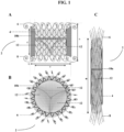
- FIG. 1 provides three views of an exemplary prosthesis 2.
- Prosthesis 2 comprises a stent 4 having an upper anchoring flange 6 and a lower anchoring flange 8. As shown in FIGS. 1A and 1C , respectively, stent 4 has an expanded state and an unexpanded state.
- FIG. 1B provides a top perspective of exemplary prosthesis 2.
- Upper flange 6 and lower flange 8 comprise individual stent elements that are substantially coiled when stent 4 is in the expanded state ( FIGS. 1A, 1B ) and are substantially straightened when stent 4 is in the unexpanded state ( FIG. 1C ).
- Prosthesis 2 also comprises a cuff 10a, 10b that is disposed circumferentially around the outer surface of stent 4. As shown in FIG. 1C , before prosthesis 2 is positioned at the site of implantation, cuff 10a will not have expanded by absorption of fluid. However, as depicted in FIGS.
- Prosthesis 2 also includes leaflets 12 that are fixedly attached to the interior surface of stent 4.
- the prosthesis depicted in FIG. 1 includes three leaflets, which can most clearly be ascertained in FIG. 1B .
- a mitral valve prosthesis comprising a self-expanding stent comprising an outer surface, an interior surface, a middle region, an upper anchoring flange, and a lower anchoring flange, wherein the stent has an unexpanded and an expanded state; a cuff comprising an absorbent material disposed at least partially circumferentially around the outer surface of the stent and a valve comprising at least two leaflets fixedly attached to the interior surface of the stent; and expanding the cuff by absorption of a fluid to substantially adhere the prosthesis at an implantation site, wherein the adhering is delayed for a time sufficient to permit positioning of the prosthesis at the implantation site.
- Delivery of the mitral valve prosthesis to an implantation site may be accomplished transatrially, transapically, or percutaneously. Delivery of the prosthesis may be followed by one or more positioning steps (i.e. , positioning and, if desired, repositioning), whereby the location of the prosthesis may be adjusted for optimal positioning in relation to the mitral valve annulus.
- positioning steps i.e. , positioning and, if desired, repositioning
- FIG. 3 For transatrial delivery, an exemplary procedure may be performed as follows and as illustrated in FIG. 3 .
- a small (2 -3 cm) thoracotomy through the inter costal space is made ( FIG. 3A ).
- the inter-atrial plane is developed.
- FIG. 3B the right atrium 14 is retracted, and a purse string suture is placed in the left atrium 16.
- Right pulmonary veins are shown as item 18.
- a steerable introducer catheter 20 is placed into the left atrium through the purse string ( FIG. 3C ).
- the catheter is advanced through the mitral valve annulus ( FIG. 3D ). Its position may be guided and confirmed by echocardiography.
- the prosthesis 2 is introduced through the catheter 20.
- the ventricular flange expands first and anchors to the ventricular side of the annulus and the subvalvular apparatus (leaflets, chordea, left ventricular wall) ( FIG. 3E ).
- the remainder of the stent and atrial flange are delivered, also under echocardiographic guidance (not shown).
- the atrial flange expands and anchors to the annulus and left atrium.
- the sealing cuff remains flaccid during the ensuing 60 minutes to allow documentation by echocardiography that the valve's position and function are adequate. After an hour in place the cuff 10b fully expands to seal the device against the native mitral valve annulus ( FIG. 3F ).
- an exemplary procedure may be performed as follows. A small left thoracotomy is performed - similar in size to that which is used during the transatrial delivery procedure. A purse string suture is place in the left ventricular apex. A steerable catheter introducer is then placed into the left ventricle through the purse string. The introducer catheter 20 is guided through the mitral valve annulus into the left atrium under echocardiographic guidance.
- the device may be designed so that the atrial flange is deployed and positioned first.
- the sealing technology by means of the cuff and optional webbing may be similar to that described above with respect to the exemplary transatrial delivery process.
- Percutaneous delivery may be venous or arterial.
- the prosthesis is configured accordingly, e.g., foldable enough to be placed via peripheral venous or arterial access.
- Venous percutaneous delivery may be performed as follows and as illustrated in FIG. 4 .
- Access to the femoral vein is achieved by standard techniques that will be readily appreciated by those skilled in the art.
- a steerable catheter 20 is then introduced into the venous system and guided to the right atrium using fluoroscopic guidance ( FIG. 4A ). Once in the right atrium, standard techniques are used to traverse the catheter across the intra-atrial septum to the left atrium ( FIG. 4B ).
- the prosthesis 2 is then deployed under echocardiographic guidance as described in the transatrial approach.
- an exemplary procedure may be performed as follows. Access to the femoral artery is achieved by standard techniques. A steerable catheter is then introduced into the arterial system and guided to the aortic root and into the left ventricle using fluoroscopic guidance. Once in the left ventricle the device is deployed as described above in connection the transapical approach.
- the following description pertains to a second general embodiment of the present disclosure, which pertains to inventive valve prostheses; methods for replacing a damaged or diseased valve; systems for delivering a valve prosthesis; kits; and, methods for delivering a valve prosthesis.
- valve prostheses comprising an at least partially self-expanding stent comprising a wire framework defining outer and interior surfaces, and upper and lower anchoring flanges interposed by a middle region, the stent having an unexpanded and an expanded state, and the lower anchoring flange having at least one geometric dimension that is greater than the corresponding dimension of the upper anchoring flange; and a valve comprising at least one leaflet fixedly attached to the interior surface of the stent.
- the stent may be configured to be at least partially self-expanding.
- the stent may be capable of self-expanding to its state of maximal expansion, or, to at least some degree, the stent may be configured such that it must be forcibly expanded, for example, by a balloon.
- the stent may be configured so that 100% of its requisite expansion occurs without any contribution by a mechanism other than the stent itself, or may be configured so that 99% or less, but more than 0%, of the requisite expansion occurs without any contribution by a mechanism other than the stent itself.
- the stent is fully self-expanding.
- the at least partially self-expanding stent may comprise a shape-memory or "superelastic" material exhibiting large elastic strains.
- An exemplary material is nitinol, a nickel-titanium alloy.
- the stent comprises a nitinol wire weave. Any other material possessing similar characteristics may also be used in the construction of the self-expanding stent, and more generally, and suitable, biocompatible material may be used to form the stent, whether it is self-expanding or not.
- Exemplary materials include stainless steel, cobalt/chromium alloy, cobalt/chromium/nickel alloy, nickel/chromium alloy, platinum, platinum/iridium alloy, among others.
- the stent may comprise one or more other materials that are themselves not self-expanding but that do not inhibit or otherwise interfere with the ability of the stent to self-expand.
- any biocompatible material may be included to add any other desired structural feature to the stent.
- Exemplary biocompatible materials include stainless steel, tantalum, platinum alloys, niobium alloys, and cobalt alloys, among others.
- one or more bioabsorbable materials may be used in forming the stent.
- Part or all of the stent may be coated with a composition comprising a drug, so that the stent is capable of eluting drug in situ.
- the stent comprises a wire framework that is formed from the material that allows the stent to be at least partially self-expanding, in addition to any other compatible materials as described above.
- the framework can be formed from wire using conventional techniques, such as coiling, weaving, braiding, or knitting.
- the stent comprises a wire weave.
- the wire framework may be welded or otherwise joined at some or all crossover points, thereby forming a structure that, at least in some places, is not hinged.
- the formation of wire frameworks is readily appreciated among those skilled in the art and the present disclosure is intended to embrace any suitable technique, including any functionally acceptable framework geometry.
- the present inventors have found that the amount of radial force that is exerted by a stent can be an important determinant both of how well the stent will be anchored to the site of implantation and of the quality of the seal that is formed between the stent and the site of implantation, e.g., between the stent and the inner walls of a valve annulus.
- the thickness of the wire that is used to form the framework influences the degree of radial force that the stent exerts.
- the thickness of the wire that is used to form the framework may be about 0,0127 cm to about 0,076 cm /0.005 inches to about 0.030 inches).
- the wire may have a thickness of about 0,025 cm, about 0,038 cm, about 0,051 cm, about 0,064cm, or about 0,076 cm (about 0.010 inches, about 0.015 inches, about 0.020 inches, about 0.025 inches, or about 0.030 inches).
- the density of the wire framework affects the radial force that is exerted by the stent. The parameters that can be used to describe the density of the wire framework are defined more fully infra.
- the radial force that is exerted by the stent is influenced by the diameter of the stent in the expanded state relative to the diameter of the major dimension of the valve annulus into which the stent is to be implanted.
- Valve annuli may be roughly circular, but in many instances are substantially elliptical or saddle-shaped, such that the annulus will have a major and a minor dimension (diameter). In the case of a circular annulus, the "major dimension" will simply be the diameter of the annulus. It has presently been discovered that the stent exerts a beneficial amount of radial force when the diameter of the stent in its expanded state is about 95% to about 125% of the major dimension of the valve annulus.
- an expanded stent having a diameter that is about 95%, about 100%, about 105%, about 110%, about 115%, about 120%, or about 125% of the major dimension of the valve annulus will be conducive to the exertion of a beneficial amount of radial force. Stated, in absolute terms, this can mean that an expanded stent may have a diameter of about 25 to about 50 mm.
- the stent comprises a middle region having various dimensions, including an unexpanded length, an unexpanded diameter, an expanded length, and an expanded diameter.
- the unexpanded length is preferably substantially the same as or greater than the expanded length, and the expanded diameter is greater than the unexpanded diameter.
- the unexpanded diameter may be any size that enables the unexpanded stent to be translated through a subject's vasculature during delivery.
- the unexpanded diameter may be of a size that enables the unexpanded stent to fit within the interior of a catheter (or a related component, such as a compression sleeve, which is more fully described herein) having a diameter of about 1 mm to about 13 mm, preferably about 1 mm to about 8 mm.
- the expanded length may substantially correspond to the length that is about the same as or longer than that of the annulus between two chambers of a human subject's heart, or between one chamber and the associated artery, such as the left ventricle and the aortic artery.
- the expanded length of the stent is longer than that of such an annulus.
- a particular subject may be matched with a stent having an expanded length that is appropriate for the valve annulus of that subject.
- the expanded length may be about 0.5 cm to about 5 cm, about 1 cm to about 4 cm, about 1.5 cm to about 3.5 cm, or about 2 cm to about 3 cm.
- the expanded diameter may be about 95% to about 125% of the major dimension of the subject's valve annulus.
- the present prosthesis further comprises a cuff comprising an absorbent material that is disposed at least partially circumferentially around the outer surface of the stent, which is discussed more fully herein, the expanded diameter preferably falls within the range recited above relative to the major dimension of the subject's valve annulus.
- the prostheses according to the present disclosure may be configured to be delivered transatrially, transapically, or percutaneously.
- the dimensions of the prosthesis, the type of material used for the stent, cuff, or other components, the presence or absence of a drug coating on the stent, the type of flanges that are included, the framework pattern ( e.g. , weave) of the stent, the length of delay of absorption of fluid, and other factors may all be manipulated in order to configure the prosthesis for transatrial, transapical, or percutaneous delivery, as desired.
- the self-expanding stent comprises an upper flange and a lower flange.
- one or both of the flanges comprise the longitudinal ends or margins of the middle region.
- one or both of the flanges may be a "lip" of stent material that extends partly or fully around the circumference of the stent at a longitudinal end of the middle region.
- one or both of the flanges may be configured to provide an anchoring functionality that substantially affixes the stent at the location of the valve annulus.
- the lower flange may be configured to anchor to the ventricular side of a mitral annulus
- the upper flange may be configured to anchor to the atrial side of the mitral annulus.
- the respective configurations of the upper and lower flange may, but need not be, the same; thus, the lower flange may adopt a different configuration than the upper flange.
- the upper flange, lower flange, or both may comprise a plurality of protruding stent elements. Any flange design, whether consisting of a unitary structure or numerous discrete elements, is contemplated for purposes of the present disclosure.
- the flanges may comprise a plurality of protruding stent elements that respectively comprise individual wires or bundled sets of wires.
- the plurality of wires may comprise a regularly or irregularly spaced array, and the wires themselves may be present as single strands, or as grouped or bundled sets of two, three, four, or more wire strands.
- the flanges may comprise a plurality of wire loops.
- the wire loops may be integral with the wire framework of the stent.
- the stent may comprise wire weave that defines (in addition to the other elements of the stent) flanges that comprise a plurality of wire loops.
- the wire loops may comprise a regularly or irregularly spaced array.
- Each flange may have a configuration that corresponds to the unexpanded state of the stent, and a configuration that corresponds to the expanded state of the stent.
- the elements may be substantially straightened when the stent is in the unexpanded state and may be substantially coiled when the stent is in the unexpanded state.
- a flange may comprise one or more elements that define flaps, lobes, loops, or other projections that may be oriented substantially parallel with the long axis of the stent when the stent is in an unexpanded state and are differently oriented when the stent is in an expanded state.
- the upper flange and lower flange each comprise a plurality of protruding stent elements that are each substantially straightened when the stent is in the unexpanded state and are each substantially bent back towards the middle region of the stent when the stent is in the expanded state.
- a stent that comprises a lower anchoring flange having at least one geometric dimension that is greater than the corresponding dimension of the upper anchoring flange is capable of reliably adhering the prosthesis to the site of implantation.
- replacement of damaged or diseased valves consisted of the removal of the defunct valve tissue in order to clear a space for the prosthetic valve apparatus and avoid unwanted interference with the functioning of the prosthesis.
- the present design does not require the removal of defunct valve tissue, and in fact benefits from the presence of such tissue, because it is capable of grasping the tissue that is present at the site of implantation (whether such tissue comprises defunct valve material or otherwise) by virtue of the lower anchoring flange, and is capable of similar grasping, as well as "capping', by virtue of the upper anchoring flange.
- the inventive prosthesis securely adheres to the site of implantation because, inter alia, of the action of lower anchoring flange to grasp the defunct valve tissue and annulus tissue on the ventricular side, and of the action of the upper anchoring flange to grasp such tissue and likewise provide a "cap" on the atrial side of the annulus.
- the terms “lower” and “upper” are merely terms of convenience; a prosthesis for implantation in a mitral valve annulus, for example, will be positioned in situ such that the "lower” anchoring flange is oriented on the ventricular side of the annulus and thereby substantially “downwards", and the convention therefore arose to use the term “lower” to designate the ventricular-side flange, which possesses a geometric dimension that is greater than the corresponding dimension on the upper flange.
- the terms “upper” and “lower” are merely conventions, there is no requirement for the "lower” anchoring flange to be oriented substantially or even partially “downwards” when the prosthesis is used in other contexts.
- the geometric dimension that is greater in the lower anchoring flange as compared with the upper anchoring flange may be any dimension that is shared by the respective flanges.
- the geometric dimension may be length, width, height, or any other parameter.
- the lower anchoring flange comprises a plurality of protruding stent elements of equal length, wherein the protruding stent elements of the lower anchoring flange are longer than a series of protruding stent elements that form the upper anchoring flange.
- the lower anchoring flange may be said to have a geometric dimension that is greater than the corresponding dimension of the upper anchoring flange when more than 50%, more than 60%, more than 70%, more than 75%, more than 80%, more than 85%, more than 90%, more than 95%, or 100% of the protruding stent elements of the lower flange have a greater dimension than the protruding stent elements of the upper flange.
- FIG. 5 provides views of an exemplary stent 21 of this variety, having an upper flange 22 and a lower flange 24 of which each comprises a plurality of protruding stent elements 26.
- Protruding stent elements 26 are substantially straightened and oriented substantially parallel with the long axis Y when stent 21 is in an unexpanded state ( FIG. 5A ) and that are substantially bent back towards the middle region 28 when stent 21 is in the expanded state ( FIG. 5B ).
- the stent 21 of FIG. 5B is vertically inverted relative to that of FIG. 5A , i.e., the upper flange 22 in FIG. 5B appears at the bottom of the drawing of stent 21, rather than at the top portion (as in FIG.
- the protruding stent elements 26 of the lower flange 24 are longer than the protruding stent elements 26 of the upper flange 22.
- the protruding stent elements 26 exert a force in the direction of the stent body, such that any material that is interposed between a protruding element 26 and the outer surface of the middle region of the stent 28 will be trapped between the two elements.
- Example 2 discloses the measurement of the force that was required to extract an exemplary valve prosthesis according to the present disclosure from a site at which the prosethesis had been implanted.
- FIG. 5B denotes various dimensions of exemplary stent 21 in its expanded state.
- Line a designates the diameter of stent 21;
- line b indicates the length of the individual protruding stent elements 26 of the lower flange 24;
- line c designates the height of stent 21, including the contribution of the upper and lower flange elements 22, 24;
- line d refers to the height of middle region 28;
- line e) points to the diameter of the lower flange elements 24 that are bent back towards middle region 28; and, line f) designates the diameter of the upper flange elements 22 that are bent back towards middle region 28.
- the diameter of the stent in its expanded state may be, for example, about 25 to about 55 mm.
- the length of an individual protruding stent element of a lower flange may be, for example, about 5 to about 45 mm.
- the height of the stent in its expanded state i.e. , the dimension running parallel to the stent lumen - designated by line c in FIG. 5B ), including the contribution of the upper and lower flange elements, may be, for example, from about 15 to about 55 mm.
- the height of the middle region alone when the stent is in its expanded state may be, for example, about 15 to 45 mm.
- the diameter of the lower flange elements that are bent back towards the middle region (as designated by line e in FIG.
- the diameter of the upper flange elements that are bent back towards the middle region of the stent (as designated by line f in FIG. 5B ) may be, for example, about 3 to about 12 mm.
- the total length of the stent may be from about 4 to about 15 cm, and the width of the compressed stent at the middle region 28 may be about 5 to about 15 mm, preferably about 6 to about 12 mm.
- the amount of outward radial force that is exerted by the stent is influenced by, inter alia, the density of the wire framework. In general, a higher density results in the exertion of a greater outward radial force.
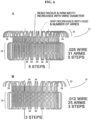
- FIG. 6 provides an illustrative example of how to characterize wire weave density, as well as how wire weave density and wire thickness respectively affect various parameters of the inventive stent 21. The process of constructing a wire weave may described in terms of "steps" and "step-overs".
- FIG. 6A shows one embodiment of an inventive stent 21 comprising wire weave that includes an upper flange 22 comprising thirty-one individual protruding stent elements and a lower flange 24 comprising thirty-one individual protruding stent elements.
- each individual protruding stent element 26 constitutes a "step” in the construction process, and each "step” requires 5 “step-overs” to form the body of the stent 21.
- FIG. 6B shows a further embodiment of an inventive stent 21 comprising wire weave that includes an upper flange 22 comprising twenty-five individual protruding stent elements and a lower flange 24 comprising twenty-five individual protruding stent elements.
- each individual protruding stent element 26 constitutes a "step” in the construction process, and each "step” requires 3 "step-overs" to form the body of the stent 21.
- the number of "step-overs” that may be used to form a stent comprising wire weave according to the present invention can be 2, 3, 4, 5, 6, 7, 8, 9, or 10.
- FIGS. 6A and 6B also illustrate how the thickness of the wire that is used to form a stent 21 comprising wire weave can influence certain characteristics of the stent.
- the embodiment of FIG. 6A involves the use of wire having a thickness of 0.025 inches
- the embodiment of FIG. 6B involves the use of wire having a thickness of 0.012 inches.
- the terminal bend of each individual protruding stent element 26 is wider in the case of the embodiment of FIG. 6A as compared with the corresponding elements of FIG. 6B , because thicker wire is used in the case of the former than in the latter.
- the thickness of the wire that is used to form the framework of an inventive stent may be about 0.005 inches to about 0.030 inches.
- the present valve prostheses may also comprise a cuff comprising an absorbent material that is disposed at least partially circumferentially around the outer surface of the stent.
- a cuff comprising an absorbent material that is disposed at least partially circumferentially around the outer surface of the stent.
- the term "cuff" is intended to embrace a continuous ring of absorbent material that forms a complete circle around the outer surface of the stent; any other conformation that involves a contiguous portion of absorbent material, such as a strip that forms a spiral around the outer surface of the stent; one, two, three or more disparate patches or strips (or any other shape or configuration) of absorbent material disposed on the outer surface of the stent; or, any combination of one or more contiguous portions of material and disparate patches, strips, and the like.
- the cuff comprises a continuous ring of absorbent material that forms a complete circle around the outer surface of the stent.
- the cuff comprises an absorbent material that expands by absorption of a fluid to substantially adhere the prosthesis at the implantation site.
- the implantation site is the mitral valve annulus.
- adhere may mean to substantially affix or anchor the prosthesis at the implantation site, to create a seal between the cuff and the mitral valve annulus that is substantially impermeable to fluid, or both.
- the cuff can form a seal that reliably prevents perivalvular leakage between the atrium and ventricle, such that when the prosthesis is in place, the only fluid that passes between the atrium and ventricle is that which is allowed to pass by the activity of the replacement valve itself.
- the adhering of the prosthesis is delayed for a time sufficient to permit positioning of the prosthesis at the implantation site.
- the procedure for positioning the prosthesis via a catheter at the implantation site may last 40 minutes, the expansion by the cuff by absorption of fluid to a sufficient degree such as to adhere the prosthesis to the implantation may be delayed until that time has elapsed.
- the cuff comprises one or more materials, components, or both that creates a delay in the absorption of fluid or that provides a sufficiently slow rate of absorption of the fluid, such that the cuff does not expand to the degree required to adhere the prosthesis to the implantation site until the desired period of delay has elapsed.
- the period of delay may be measured starting at the point in time where the prosthesis is exposed to a fluid (e.g., blood).
- the delay period may be about 1 minute, about 2 minutes, about 5 minutes, about 7 minutes, about 10 minutes, about 15 minutes, about 20 minutes, about 30 minutes, about 45 minutes, about 1 hour, about 75 minutes, about 90 minutes, or about 2 hours.
- the type of cuff that is selected for use with the prosthesis may depend on the difficulty of the procedure to deliver the prosthesis to the implantation site.
- the absorbent material of the cuff may itself absorb fluid at a sufficiently slow rate to delay the adhering of the prosthesis at the implantation site.
- the absorbent material of the cuff may feature a variable rate of absorption, such that the rate of absorption is low for an initial period of time but that increases over time or after a period of time.
- the absorbent material may have a fluid absorption rate of about 0 ⁇ L to about 20 ⁇ L per minute for a first period of time following exposure of the prosthesis to the fluid, and a fluid absorption rate from about 10 to about 200 ⁇ L per minute after the first period of time.
- the period of time after which the rate of absorption increases may be about 10 minutes, about 15 minutes, about 20 minutes, about 30 minutes, about 45 minutes, about 1 hour, about 90 minutes, about 2 hours, about 180 minutes, or about 2 hours.
- the ability of the absorbent material of the cuff to absorb fluid is delayed.
- the absorbent material of the cuff may be completely or partially covered with or contained within a material that affects the ability of the absorbent material to absorb fluid.
- the absorbent material may be completely or partially covered with or contained within a cover material, e.g., a film or fabric, that is permanently impermeable to fluid, but that is removable and is removed when the desired period of delay has elapsed; the removal of the cover material may be effected while the prosthesis is in situ at the implantation site, for example, by using a catheter-based removal tool to grasp and remove the cover material.
- a cover material e.g., a film or fabric
- Any material that is substantially impermeable to fluid such as water, blood, and the like
- Nonlimiting examples include polyurethanes, polyethylenes, polydimethylsiloxane, silicones, rubbers, and polyvinyl chloride.
- the absorbent material may be completely or partially covered with or contained within a cover material, e.g., a film or fabric, that is temporarily impermeable to fluid, but that becomes permeable to fluid after a desired period of delay.
- a cover material e.g., a film or fabric
- the cover material may be degradable over time, or may comprise a material that degrades or is altered in response to a change in temperature, pH, or some other environmental cue that is present at the implantation site.
- the absorbent material may be completely or partially covered with or contained within a cover material that is permeable to fluid, but the transfer of fluid across such cover material and/or saturation of by the cover material by fluid is sufficiently slow to provide a delay before the absorbent material absorbs a sufficient amount of fluid to adhere to the implantation site.
- the period of delay that is provided by a cover material may be, for example, about 5 minutes to about 3 hours, about 10 minutes to about 3 hours, about 20 minutes to about 2 hours, about 30 minutes to about 2 hours, about 45 minute to about 90 minutes, or about one hour following exposure of the prosthesis to a fluid.
- the ability of the absorbent material of the cuff to absorb is delayed because the absorbent material itself or a material that is mixed in or otherwise substantially interspersed or integrated with the absorbent material is altered in response to one or more conditions (e.g. , temperature, pH, and the like) that are present at the implantation site.
- the absorbent material may include or may be provided along with a polymer that changes shape over time in response to exposure to the fluid or some other environmental cue present at the implantation site, and such shape change permits the initiation or the acceleration of the absorption of fluid by the absorbent material.
- Exemplary substances that may be used to form the absorbent material include any crosslinked hydrogel component.
- a crosslinked hydrogel component may be based on covalent crosslinks, physical/ionic crosslinking, or both.
- Nonlimiting examples include poly(acrylic acid), poly(ethylene glycol), polyethylene oxide), polypropylene oxide), poly(vinyl alcohol), polyvinyl pyrrolidinone, poly(hydroxy ethyl methacrylate), poly(amino acids), Dextran, polysaccharides, and proteins.
- substances that may be used to form the absorbent material include sodium polyacrylate, polyacrylamide copolymer, ethylene maleic anhydride copolymer, carboxy-methyl-cellulose polyvinyl alcohol copolymers, polyethylene oxide, and polyacrylonitrile.
- any “super absorbent” material for example, a super absorbent polymer, also may be used in the cuff, when present.
- a “super absorbent” material is one that features an increase in volume swelling ratio (Qv; swollen volume divided by "dry” volume or volume before any fluid has been absorbed) from 1 to about 5-1000.
- Qv volume swelling ratio
- Those of ordinary skill in the art can readily identify other suitable materials that may be characterized as "super absorbent” and any such material may be used.
- the cuff is configured so that expansion occurs predominantly in a single direction. For example, the expansion may predominantly in a direction that is substantially perpendicular relative to the outer surface of the stent.
- the direction of expansion of the absorbent material may be characterized as radial. Because the stent in its expanded state will be sufficiently rigid to resist compression as a result of any radial expansion by the absorbent material in the direction towards the surface of the stent, the radial expansion of the absorbent material will be substantially unidirectional in the direction away from the surface of the stent, i.e., towards the interior surface of the mitral valve annulus. As described above, the expansion of the absorbent material can enhance the seal between the cuff and the valve annulus that prevents perivalvular leakage.
- a prosthesis according to the present disclosure may further comprise a webbing that is disposed at the upper flange, lower flange, or both.
- the webbing may comprise an absorbent material.
- the presence of the webbing may assist with the adhering (i.e. , the affixing, anchoring, and/or sealing) of the prosthesis at the implantation site. Accordingly, the webbing may expand by absorption of a fluid, and the resulting adhering may be delayed for a time sufficient to permit positioning of the prosthesis at the implantation site.
- a portion of the webbing may be disposed between at least one pair of the protruding stent elements of either or both of the flanges.
- the webbing is disposed between a plurality of pairs of protruding stent elements of the upper anchoring flange and between a plurality of pairs of protruding stent elements of the lower anchoring flange.
- the webbing may comprise one or more materials, components, or both that creates a delay in the absorption of fluid or that provides a sufficiently slow rate of absorption of the fluid, such that the webbing does not expand to the degree required to adhere the prosthesis to the implantation site until the desired period of delay has elapsed.
- the prostheses of the invention also comprise a valve comprising at least one leaflet that is fixedly attached to the interior surface of the stent.
- the attachment of the leaflet or leaflets to the interior surface of the stent need not be direct; for example, a valve support ring may be fixedly attached to the interior surface of the stent, and the valve(s) may be fixedly attached to the valve support ring.
- the valve may comprise one leaflet, two leaflet, or three leaflets.
- the leaflets are preferably derived from a biological source, such as mammalian pericardium.
- the leaflets may be made from bovine, equine, ovine, caprine, or porcine pericardium.
- the leaflets may be derived from animal valves, preferably mammalian valves.
- animal valves preferably mammalian valves.
- Nonlimiting examples include bovine jugular vein valves, porcine pulmonary valves, and porcine aortic valves.
- porcine aortic valves Those of ordinary skill in the art will appreciate how to select the appropriate valve for the desired purpose. For example, it will be recognized that the suitability of a particular type of valve and number of leaflets may be affected by the intended use of the valve prosthesis. In one instance, the intended use of the valve prosthesis may be the replacement of a damaged or diseased mitral valve, in which case it would be appreciated that a three-leaflet valve should be selected.
- the instant prostheses may be configured for replacing any cardiac valve, such as the pulmonary valve, the tricuspid valve, the aortic valve, or the mitral valve.
- the present disclosure also includes methods for replacing a damaged or diseased valve in a subject comprising: delivering to an implantation site of the subject a valve prosthesis comprising an at least partially self-expanding stent comprising a wire framework definingouter and interior surfaces, and upper and lower anchoring flanges interposed by a middle region, the stent having an unexpanded and an expanded state, and the lower anchoring flange having at least one geometric dimension that is greater than the corresponding dimension of the upper anchoring flange; and a valve comprising at least one leaflet fixedly attached to the interior surface of the stent; and expanding the stent to substantially adhere the prosthesis at the implantation site.
- Delivery of the valve prosthesis to an implantation site may be accomplished transatrially, transapically, or percutaneously. Delivery of the prosthesis may be followed by one or more positioning steps (i.e., positioning and, if desired, repositioning), whereby the location of the prosthesis may be adjusted for optimal positioning in relation to the valve annulus.
- positioning steps i.e., positioning and, if desired, repositioning
- an exemplary procedure may be performed as follows. A small (2-3 cm) thoracotomy through the inter costal space is made. The inter-atrial plane is developed. The right atrium is retracted, and a purse string suture is placed in the left atrium. Then, a steerable introducer catheter is placed into the left atrium through the purse string. The catheter is advanced through the mitral valve annulus. Its position may be guided and confirmed by echocardiography. The prosthesis is introduced through the catheter. The lower (ventricular) flange expands first and anchors to the ventricular side of the annulus and the subvalvular apparatus (leaflets, chordea, left ventricular wall).
- the remainder of the stent and upper (atrial) flange are delivered, also under echocardiographic guidance.
- the atrial flange expands and anchors to the annulus and left atrium.
- the sealing cuff remains flaccid during the ensuing 60 minutes to allow documentation by echocardiography that the valve's position and function are adequate. After an hour in place the cuff fully expands to seal the device against the native mitral valve annulus.
- an exemplary procedure may be performed as follows. A small left thoracotomy is performed - similar in size to that which is used during the transatrial delivery procedure. A purse string suture is place in the left ventricular apex. A steerable catheter introducer is then placed into the left ventricle through the purse string. The introducer catheter is guided through the mitral valve annulus into the left atrium under echocardiographic guidance.
- the device may be designed so that the atrial flange is deployed and positioned first.
- the optional cuff and/or webbing may be similar to that described above with respect to the exemplary transatrial delivery process.
- Percutaneous delivery may be venous or arterial.
- the prosthesis is configured accordingly, e.g., foldable enough to be placed via peripheral venous or arterial access.
- Venous percutaneous delivery may be performed as follows. Access to the femoral vein is achieved by standard techniques that will be readily appreciated by those skilled in the art. A steerable catheter is then introduced into the venous system and guided to the right atrium using fluoroscopic guidance. Once in the right atrium, standard techniques are used to traverse the catheter across the intra-atrial septum to the left atrium. The prosthesis is then deployed under echocardiographic guidance as described in the transatrial approach.
- an exemplary procedure may be performed as follows. Access to the femoral artery is achieved by standard techniques. A steerable catheter is then introduced into the arterial system and guided to the aortic root and into the left ventricle using fluoroscopic guidance. Once in the left ventricle the device is deployed as described above in connection the transapical approach.
- a valve prosthesis comprising an at least partially self-expanding stent to an implantation site comprising: a catheter comprising a distal end and a proximal end, a guidewire lumen to permit the catheter to be translated along a guidewire, a steering lumen for accommodating a tension cable for steering the catheter, and a dock at the distal end onto which the stent may be loaded.
- the present systems also comprise a retractable compression sleeve for compressing at least a portion of the stent while the stent is loaded onto the dock; a leading tip positioned distal to the dock for leading the catheter during delivery; and, a steering mechanism operably associated with the tension cable for deflecting the leading tip in at least one directional plane.
- the disclosed systems are capable of housing, transporting, and delivering stents of valve prostheses according to the present disclosure, as well as stents of other configurations, including conventional stented devices.
- the present systems include a number of features that address certain challenges that are associated with the manipulation and implantation of at least partially self-expanding stents, including those having the characteristics of the stents that are used with the presently disclosed prostheses.
- the catheter of the present system includes a distal end, which is the end of the catheter that is first introduced into the physiological point of entry during the stent implantation procedure.
- the proximal end of the catheter (defined herein as the end of the catheter that is closest to the operator of the system during use) remains outside of the subject.
- the instant catheters may have a length of about 20 cm to about 200 cm from the distal end to the proximal end.
- the outer diameter of the catheter may be about 0.5 cm to about 1.5 cm.
- the catheter may be constructed from any suitable material, wherein suitability is determined by such considerations as biological compatibility, durability, the appropriate balance between rigidity and flexibility, and other readily appreciable factors based on the intended use of the catheter.
- suitable material for example, polyimide, polyethylene, polypropylene, Kalrez ® , Simriz ® , Viton ® , Chemraz ® , silicone, neoprene, nitrile, metal or metal alloys (such as Ti-Nb-Zr; see, e.g., U.S. Pat. No. 5,685,306 ) or any other combination thereof may be used.
- the materials used for the construction of the catheter, as well as the methods for the construction thereof, are readily appreciated by those skilled in the art, and all appropriate materials and means of construction are contemplated herein.
- the catheter includes at least two lumens, the first being a guidewire lumen to permit the catheter to be translated along a guidewire, the second being a steering lumen for accommodating a tension cable for steering the catheter.
- the guidewire lumen is appropriately sized, shaped, and located within the catheter to accommodate a guidewire, such that the catheter may be translated over a guidewire that has been placed along the appropriate physiological pathway to a site of interest within a subject.
- the steering lumen is appropriately sized, shaped, and located within the catheter to accommodate a tension cable. The manipulation of a tension cable that is located within a lumen of the present catheters causes the deflection of the catheter, which in turn allows the catheter to be moved from a first location to a second location in situ.
- guidewires and steering tension cables are well known among those skilled in the art.
- a guidewire lumen it is traditional for a guidewire lumen to be located towards the center of a catheter.
- the guidewire lumen and the steering lumen are provided in a side-by-side arrangement within the catheter.
- the guidewire lumen may be located substantially in the center of the catheter, and the steering lumen is located between the guidewire lumen and the outer surface of the catheter. It may be desirable to include more than one steering lumen, wherein each steering lumen may accommodate a separate tension cable, in order to enhance the steerability of the catheter.
- an exemplary catheter may include a single guidewire lumen and two, three, or four separate steering lumens.
- the catheters of the present systems further comprise a dock at the distal end of the catheter onto which a stent may be loaded.
- the dock is preferably integral with the rest of the catheter, and may simply comprise a distal portion of the catheter having a smaller diameter than the remainder of the catheter, or at least of the portion of the catheter that is located immediately adjacent to the dock.
- the outer diameter of the catheter (excluding the dock) may be about 0.25 cm to about 1.5 cm
- the outer diameter of the dock may be from about 25% to about 75% of the diameter of the remainder of the catheter. Stated in absolute terms, the outer diameter of the dock may be about 0.10 cm to about 0.80 cm.
- the length of the dock is preferably at least as long as a stent in its fully compressed state (of which exemplary lengths are provided above in connection with the presently disclosed prostheses), and may be somewhat longer than a compressed stent. Stated in absolute terms, the length of the dock may be from about 4 cm to about 15 cm.
- the dock may optionally comprise an inflatable balloon for expanding or assisting with the expansion of a stent that is loaded onto the dock.
- inflatable balloons for the expansion of stents is well known among skilled artisans. Because such balloons are typically actuated at a desired time via the selective induction of fluid (liquid or gas) pressure, when the dock comprises an inflatable balloon, the catheter may further comprise a balloon lumen for supplying the fluid (for example, saline, water, or CO 2 gas) that is used to inflate the balloon.
- the balloon When inflated, the balloon may adopt any configuration that is suitable for assisting with the expansion of the stent; for example, the inflated balloon may be an elongated torus or a series of two or more tori that are distributed along the length of the dock.
- the present systems further comprise at least one retractable compression sleeve for compressing at least a portion of the stent while the stent is loaded onto the dock.
- the compression sleeve is preferably in coaxial arrangement with the catheter, for example, functioning like a cannula or outer covering that translates over the catheter in a direction that is towards or away from the catheter's distal end.
- a stent may be loaded onto the dock in a compressed state, and the compression sleeve may be translated over the dock so that it passes over and encircles the compressed stent; in this way, the compression sleeve ensures that the stent remains compressed while loaded onto the dock.
- Specialized techniques may be required to load the stent onto the dock in a compressed state.
- the distal end of the catheter may be delivered to the site of implantation, where the compression sleeve is eventually withdrawn and the stent thereby permitted to expand at the implantation site.
- a compression sleeve may be made from any material that is biocompatible and is capable of functioning in the described manner.
- a compression sleeve may be constructed from a rigid material so that it is not damaged or distorted by the outward radial force that is exerted by the compressed stent.
- the interior and/or exterior surfaces of the compression sleeve are preferably configured to result in a low coefficient of friction against any other component or physiological feature against which the sleeve may slide during use; this feature may be inherent in the material from which the sleeve is constructed, or may be imparted to the sleeve material by a low-friction coating.
- PTFE polytetrafluoroethylene
- Teflon ® polytetrafluoroethylene
- Any other suitable materials may be used, optionally coated on one or both of the inside and outside surfaces with PTFE or another material that is suitable for reducing friction.
- a single compression sleeve may be used to compress the entire stent.
- the system may comprise two or more compression sleeves; a second retractable compression sleeve, or other further compression sleeves, may be present for compressing a further portion of the stent when the stent is loaded onto the dock.
- a first compression sleeve may be present and used to keep the middle region of the stent in the compressed state, and a second compression sleeve may be used to keep the upper and lower flanges of the stent in the compressed state.
- both the first and second compression sleeves are positioned in coaxial arrangement with the dock, with the first compression sleeve being positioned directly over the stent, and the second compression sleeve being positioned over the first compression sleeve and the stent; withdrawal of second compression sleeve ( e.g., by translation over the catheter in the direction away from the dock) results in the expansion of the flanges, and subsequent withdrawal of the first compression sleeve results in the expansion of the remainder of the stent. Because of the nature of the process of withdrawing the second compression sleeve, either the upper or lower flange will expand prior to the expansion of the other of the upper and lower flanges.
- the present systems further comprise a leading tip that is positioned distal to the dock portion of the catheter and that is for leading the catheter during the delivery process.
- the leading tip may be substantially conical, may be rounded at its distal end, or may have any other configuration that enhances the ease with which the tip and thereby the trailing catheter are directed through a subject's vasculature.
- Materials that may be used to form the leading tip may include any rigid, biocompatible, and preferably low-friction material. Examples include nylon, silastic, plastic, nitinol, stainless steel, cobalt/chromium alloy, cobalt/chromium/nickel alloy, nickel/chromium alloy, platinum, and platinum/iridium alloy.
- the leading tip may be securely yet removably attachable to the distal end of the dock, so that the stent can be loaded onto the dock prior to the attachment of the leading tip.
- the systems according to the present disclosure also comprise a steering mechanism that is operably associated with the tension cable or cables and that is for deflecting the leading tip in at least one directional plane.
- the association between the steering mechanism and the tension cable or cables is described as operable because the steering mechanism makes use of its connection to the tension cable to deflect the leading tip.
- the use of tension cables for the deflection of a tension cable housing is readily understood among those skilled in the art.
- the steering mechanism may be any device that allows a user to manipulate the tension cable(s) and thereby the catheter in the intended manner - for example, an obturator knob, lever, dial, or any appropriate mechanism may be used.
- the deflection of the leading tip by use of the steering mechanism permits both the guidance of the catheter through a subject's vasculature (for example, to effect the downturn into the subject's ventricle) and the precision placement of the dock and stent at or near the site of implantation.
- the steering mechanism is typically used in conjunction with an appropriate imaging technology, such as fluoroscopy or echocardiography.
- kits comprising a system comprising an at least partially self-expanding stent to an implantation site comprising: a catheter comprising a distal end and a proximal end; a guidewire lumen to permit the catheter to be translated along a guidewire; a steering lumen for accommodating a tension cable for steering the catheter; a dock at the distal end onto which the stent may be loaded; a retractable compression sleeve for compressing at least a portion of the stent while the stent is loaded onto the dock; a leading tip positioned distal to the dock for leading the catheter during delivery; and, a steering mechanism operably associated with the tension cable for deflecting the leading tip in at least one directional plane; and, at least one valve prosthesis comprising an at least partially self-expanding stent comprising a wire framework defining outer and interior surfaces, and upper and lower anchoring flanges interposed by a middle region, the stent having an unexpanded and
- kits may further comprise one or more of the following additional components: instructions for use; replacement parts for any of the components of the system or prosthesis; and, tools for the repair of the system.
- the present kits comprise a plurality of valve prostheses, wherein the diameter of at least one of the prostheses in its expanded state is greater than the diameter of at least one other of the prostheses in its expanded state.
- Such embodiments account for the fact that user must choose a valve prosthesis that that is suitably sized in its expanded state for implantation in the particular site of interest within the particular patient at hand.
- the inner diameter of valve annuli vary within a particular patient, such that, for example, the diameter of the aortic valve annulus may be different from the diameter of the mitral valve annulus.
- the inner diameter of a particular valve annulus may vary from patient to patient, such that a first patient has a mitral valve annulus with a greater diamater than that of the mitral valve annulus of a second patient.
- a valve prosthesis must be selected to possess an appropriate diameter in its expanded state, wherein the propriety of a particular expanded diameter depends on the intended site of implantation and on the particular subject.
- kits of the present disclosure at least two prostheses, wherein the diameter of at least one of the prostheses in its expanded state is greater than the diameter of at least one other of the prostheses in its expanded state, so that a choice may be made, depending on the relevant criteria, from among at least two different "sizes" of prosethesis.
- the present kits may include at least two prostheses of which one possesses a different type of valve than at least one other prosthesis.
- a particular kit may include three valve prostheses, of which two include a replacement mitral valve, and one includes a replacement aortic valve.
- the systems that are described herein for inclusion in the present kits may be used to deliver any type of prosthesis (including a prosthesis comprising any type of valve) to a site of implantation, and the inclusion of prostheses that respectively include different types of valves enables the user to select the prosthesis that is most suitable for the intended purpose.
- FIG. 7 depicts the components of an exemplary kit according to the present disclosure.
- the kit comprises system that includes a catheter 30 that has a distal end 32 and a proximal end 34.
- FIG. 7A provides a cross-sectional view of catheter 30 that reveals the guidewire lumen 36 and three steering lumens 38.
- dock 40 is at distal end 32 of catheter 30, and leading tip 42 is positioned distal to the dock 40.
- Steering mechanism 44 is located at proximal end 34 of catheter 30 and, in the depicted embodiment, comprises an obturator knob 46.
- the kit also includes a prosthesis comprising a stent 21 that comprises a wire framework, shown in its expanded state in FIG. 7B and in its compressed state in FIG. 7C .
- the wire framework of stent 21 defines upper 22 and lower 24 flanges interposed by a middle region 28.
- a valve 29 is fixedly attached to the interior of the stent 21.
- the present disclosure also pertains to methods for delivering a valve prosthesis comprising an at least partially self-expanding stent to an implantation site comprising: (i) providing a system comprising a catheter comprising a distal end and a proximal end; a guidewire lumen to permit the catheter to be translated along a guidewire; a steering lumen for accommodating a tension cable for steering the catheter; a dock at the distal end onto which the stent may be loaded; a retractable compression sleeve for compressing at least a portion of the stent while the stent is loaded onto the dock; a leading tip positioned distal to the dock for leading the catheter during delivery; and, a steering mechanism operably associated with the tension cable for deflecting the leading tip in at least one directional plane; (ii) loading onto the dock the valve prosthesis; (iii) delivering a guidewire to the implantation site; (iv) translating the catheter over the guidewire so that the loaded valve prosthesis is positioned at the
- FIGS. 8-9 illustrate an example of how retractable compression sleeves 48, 50 may be used to compress a stent 21 against the dock 40 of a catheter 30 during delivery to an implantation site, and to permit the stent to expand at the implantation site and undock from the catheter 30.
- FIG. 8A depicts a compressed stent 21 that is mounted on dock 40 of a catheter 30; for simplicity, no compression sleeves are shown, even though the absence of a compression sleeve would ordinarily allow the stent 21 to expand.
- FIG. 8B shows how a first compression sleeve 48, shown as a dark gray layer ( see illustrative inset X), is advanced over stent 21 and functions to compress the middle region 28 of stent 21.
- Lower flange 24 is not covered by first compression sleeve 48.
- a second compression sleeve 50 shown as a lighter gray layer ( see illustrative inset Y) is advanced over both first compression sleeve 48 and stent 21, this time including lower flange 24 of stent 21. Second compression sleeve 50 therefore ensures that lower flange 24 remains compressed during delivery of the distal end of catheter 30 to an implantation site.
- FIG. 9A-C depicts in reverse order how the withdrawal of compression sleeves allows a prosthesis comprising a stent to expand in a controlled, sequential manner.
- a first compression sleeve 48 and a second compression sleeve 50 are in place in coaxial arrangement over a stent that is mounted on the dock 40 of catheter 30; in concert, compression sleeves 48, 50 compress the middle region 28 of the stent and the flanges 22, 24 such that the stent remains mounted on dock 40.
- the light gray arrows in FIG. 9C indicate the direction in which second compression sleeve 50 is withdrawn over catheter 30 in order to proceed to the next step of the process of expanding the stent at the implantation site.
- FIG. 9B shows the results of withdrawing second compression sleeve 50: lower flange 24 has commenced to expand.
- the darker gray arrows in FIG. 9B indicate the direction in which first compression sleeve 48 is withdrawn over catheter 30 in order to permit expansion of each of the components of the stent.
- first compression sleeve 48 has been fully withdrawn, and each of the lower flange 24, upper flange 22, and middle region 28 of the stent 21 have fully expanded.
- Lower flange 24 is bent back towards middle region 28, and any tissue that is interposed between these to components will be securely clamped.
- the dock of the catheter may comprise an inflatable balloon, and following retraction of a retractable compression sleeve, the method may further comprise at least partially inflating the balloon to further expand the stent.
- the stent is at least partially self-expanding, it may be desireable to use a balloon to ensure that the stent reaches its maximally expanded state.
- FIG. 10 illustrates how the process described in FIG. 9 will result in the implantation in situ of a valve prosthesis that comprises a wire framework.
- FIG. 10A the implantation process is shown at the point where catheter 30 had been advanced to the implantation site (the mitral valve annulus), with leading tip 42 having been advanced past the valve annulus into the ventricle, and the dock, loaded with a compressed valve prosthesis, having been positioned within the valve annulus.
- FIG. 10B shows how the initial withdrawal of a compression sleeve from the loaded prosthesis results in the partial expansion and deployment of lower flange 24.
- FIG. 10C the compression sleeve has been withdrawn even further, such that a greater portion of lower flange 24 has expanded.
- 10D depicts the implantation process at the point when the compression sleeve has been fully withdrawn, lower flange 24 is bent back towards middle region 28, which is fully expanded and exerting radial force against the mitral valve annulus.
- Loose tissue on the ventricular side of the mitral valve annulus has been grasped by lower flange 24, and clamped between lower flange 24 and stent middle region 28.
- Upper flange 22 is also in the fully expanded state, has grasped loose tissue on the atrial side of the mitral valve annulus, and functions as a "cap" over the tissue on the atrial side of the annulus.
- An exemplary delivery and implantation procedure may be performed as follows using the presently disclosed system for delivering a valve prosthesis, as well as a valve prosthesis according to the present disclosure.
- the femoral vein (right or left) is accessed and a vascular sheath is inserted using the seldinger technique.
- the atrial septum is crossed via standard transseptal technique, and an atrial hole is created/enlarged via balloon dilation septostomy (10-15 mm angioplasty balloon)
- a super-stiff guidewire is carefully shaped to and then positioned in the left ventricle through the newly created atrial hole.
- the femoral venous access site is made larger or "dilated up" with sequentially larger vascular dilators sized appropriately to match the diameter of the delivery system.
- the valve prosthesis is compressed and positioned on the dock of the delivery system, and the system is otherwise prepared for insertion into the femoral vein.
- the loaded delivery catheter is advanced over the wire, into the femoral vein, through the venous system, across the atrial septal defect and then positioned at the level of the mitral annulus using ECHO (transesophageal and or Intracardiac) and fluoroscopic guidance.
- ECHO transesophageal and or Intracardiac
- the steering mechanism is used to navigate the leading tip of the catheter through the vasculature and across the septum.
- deployment of the prosthesis is accomplished by sequentially withdrawing the containment sleeves, allowing the stent to expand. If necessary, the stent can be forcefully expanded to its nominal configuration by inflating a balloon located in the dock portion of the delivery catheter.
- ECHO and fluoroscopic assessment is used to confirm position and stability of the device. If all looks stable, the delivery catheter is withdrawn from the body. A large vascular sheath is placed into the femoral vein to promote hemostasis. The atrial septal defect is closed using a percutaneous closure device (Amplatzer or Helex).
- the prostheses according to the present invention exert a number of different forces on the valve annulus and surrounding material.
- Such forces contribute to the unique ability of the prosthesis to remain anchored and properly positioned at the site of implantation.
- the upper and lower flanges respectively bend back towards the middle region of the stent, and any tissue that is interposed between a flange and the middle region will be grasped by the flange and clamped between the flange and the middle region.
- the stent also exerts an outward radial force against the walls of the valve annulus.
- the knotted sutures were pulled backward, using gradually increasing force to dislodge the device from the mitral annulus.
- the target for this process was that at least 15 Newtons of force would be required to extract the prosthesis.
- the prosthesis remained affixed to the annulus at 15 Newtons, and could not be extracted until the mitral valve and chordal tissue began to tear, at a point when greater than 20 Newtons was measured. Accordingly, the aggregate of the forces that were exerted by the prosthesis on the site of implantation enabled the device to adhere to the annulus even when significant extraction forces were applied.
Landscapes
- Health & Medical Sciences (AREA)
- Cardiology (AREA)
- Engineering & Computer Science (AREA)
- Biomedical Technology (AREA)
- Heart & Thoracic Surgery (AREA)
- Transplantation (AREA)
- Oral & Maxillofacial Surgery (AREA)
- Vascular Medicine (AREA)
- Life Sciences & Earth Sciences (AREA)
- Animal Behavior & Ethology (AREA)
- General Health & Medical Sciences (AREA)
- Public Health (AREA)
- Veterinary Medicine (AREA)
- Prostheses (AREA)
- Infusion, Injection, And Reservoir Apparatuses (AREA)
Claims (9)
- Prothèse de valve mitrale comprenant :
un stent au moins partiellement auto-expansible (2 ; 4 ; 21) ayant un état expansé et un état non expansé et qui comprend :un axe long (Y) ;une région médiane comprenant une armature qui définit des surfaces interne et externe ;une partie de bride inférieure (8 ; 24) au niveau d'une première extrémité longitudinale de la région médiane qui comprend une pluralité d'éléments de stent en saillie (7 ; 26) ;une partie de bride supérieure (6 ; 22) au niveau d'une seconde extrémité longitudinale de la région médiane qui comprend une pluralité d'éléments de stent en saillie (7 ; 26) ; etune valve qui est fixée sur la surface interne de la région médiane du stent (2 ; 4 ; 21) dans laquelle, lorsque ledit stent (2 ; 4 ; 21) est à l'état non expansé, les parties de bride supérieure et inférieure sont orientées sensiblement le long de l'axe long (Y) du stent (2 ; 4 ; 21) ;dans laquelle la bride inférieure (8 ; 24) a au moins une dimension géométrique qui est supérieure à la dimension correspondante de la bride supérieure (6 ; 22),dans laquelle pendant la transition du stent (2 ; 4 ; 21) de l'état non expansé à l'état expansé, la partie de bride supérieure (6 ; 22) et la partie de bride inférieure (8 ; 24) effectuent toutes deux une transition dans l'espace de sorte qu'elles ne sont plus orientées sensiblement le long de l'axe long (Y) du stent (2 ; 4 ; 21),
etcaractérisée en ce que la partie de bride inférieure (8 ; 24) est configurée pour saisir le tissu du côté ventriculaire d'un anneau mitral en le piégeant entre la partie de bride inférieure (8 ; 24) et la surface externe de la région médiane lorsque le stent (2 ; 4 ; 21) effectue une transition de l'état non expansé à l'état expansé,dans laquelle la partie de bride inférieure (8 ; 24) est sensiblement recourbée vers la région médiane lorsque le stent (2 ; 4 ; 21) est à l'état expansé. - Prothèse de valve mitrale selon la revendication 1, dans laquelle la partie de bride inférieure (8 ; 24) est configurée pour ancrer le stent (2 ; 4 ; 21) à l'intérieur de l'anneau mitral en saisissant une paroi ventriculaire gauche entre la partie de bride inférieure (8 ; 24) et la surface externe de la région médiane.
- Prothèse de valve mitrale selon la revendication 1 ou 2, dans laquelle les éléments de la partie de bride supérieure (6 ; 22) sont des éléments de stent en saillie et la partie de bride supérieure est configurée pour ancrer le stent (2 ; 4 ; 21) à l'intérieur de l'anneau mitral en saisissant le tissu entre la partie de bride supérieure (6 ; 22) et la surface externe de la région médiane.
- Prothèse de valve mitrale selon la revendication 3, dans laquelle la partie de bride supérieure (6 ; 22) est configurée pour ancrer le stent (2 ; 4 ; 21) à l'intérieur de l'anneau mitral en saisissant le tissu du côté auriculaire de l'anneau entre la partie de bride supérieure (6 ; 22) et la surface externe de la région médiane.
- Prothèse de valve mitrale selon la revendication 3, dans laquelle la partie de bride supérieure (6 ; 22) est configurée pour ancrer le stent (2 ; 4 ; 21) à l'intérieur de l'anneau mitral en saisissant le tissu auriculaire gauche entre la partie de bride supérieure (6 ; 22) et la surface externe de la région médiane.
- Prothèse de valve mitrale selon l'une quelconque des revendications précédentes, dans laquelle ledit stent (2 ; 4 ; 21) est auto-expansible.
- Prothèse de valve mitrale selon l'une quelconque des revendications précédentes, dans laquelle le stent (2 ; 4 ; 21) comprend un tissage de fils métalliques.
- Prothèse de valve mitrale selon l'une quelconque des revendications précédentes, dans laquelle la partie de bride supérieure (6 ; 22) est orientée à un angle oblique par rapport à l'axe long (Y) du stent (2 ; 4 ; 21) lorsque le stent (2 ; 4 ; 21) est à l'état expansé.
- Prothèse de valve mitrale selon l'une quelconque des revendications précédentes, dans laquelle la partie de bride supérieure (6 ; 22) est orientée sensiblement parallèlement par rapport à l'axe long (Y) du stent (2 ; 4 ; 21) lorsque le stent (2 ; 4 ; 21) est à l'état non expansé.
Priority Applications (1)
| Application Number | Priority Date | Filing Date | Title |
|---|---|---|---|
| EP23176730.2A EP4257083A3 (fr) | 2009-11-05 | 2010-11-05 | Prothèse de valve |
Applications Claiming Priority (2)
| Application Number | Priority Date | Filing Date | Title |
|---|---|---|---|
| US25833109P | 2009-11-05 | 2009-11-05 | |
| PCT/US2010/055645 WO2011057087A1 (fr) | 2009-11-05 | 2010-11-05 | Prothèse de valve |
Related Child Applications (1)
| Application Number | Title | Priority Date | Filing Date |
|---|---|---|---|
| EP23176730.2A Division EP4257083A3 (fr) | 2009-11-05 | 2010-11-05 | Prothèse de valve |
Publications (3)
| Publication Number | Publication Date |
|---|---|
| EP2496182A1 EP2496182A1 (fr) | 2012-09-12 |
| EP2496182A4 EP2496182A4 (fr) | 2016-05-04 |
| EP2496182B1 true EP2496182B1 (fr) | 2023-06-21 |
Family
ID=43970357
Family Applications (2)
| Application Number | Title | Priority Date | Filing Date |
|---|---|---|---|
| EP10829157.6A Active EP2496182B1 (fr) | 2009-11-05 | 2010-11-05 | Prothèse de valve |
| EP23176730.2A Pending EP4257083A3 (fr) | 2009-11-05 | 2010-11-05 | Prothèse de valve |
Family Applications After (1)
| Application Number | Title | Priority Date | Filing Date |
|---|---|---|---|
| EP23176730.2A Pending EP4257083A3 (fr) | 2009-11-05 | 2010-11-05 | Prothèse de valve |
Country Status (7)
| Country | Link |
|---|---|
| US (8) | US9289291B2 (fr) |
| EP (2) | EP2496182B1 (fr) |
| JP (7) | JP2013509961A (fr) |
| CN (1) | CN102665612B (fr) |
| AU (5) | AU2010315030B2 (fr) |
| CA (2) | CA2779393C (fr) |
| WO (1) | WO2011057087A1 (fr) |
Families Citing this family (307)
| Publication number | Priority date | Publication date | Assignee | Title |
|---|---|---|---|---|
| CA2419811A1 (fr) | 2000-08-18 | 2002-02-28 | Atritech, Inc. | Dispositifs d'implant expansibles destines a filtrer le flux sanguin a partir d'appendices auriculaires |
| JP4398244B2 (ja) | 2001-10-04 | 2010-01-13 | ネオヴァスク メディカル リミテッド | 流量減少インプラント |
| IL158960A0 (en) | 2003-11-19 | 2004-05-12 | Neovasc Medical Ltd | Vascular implant |
| US7959666B2 (en) | 2003-12-23 | 2011-06-14 | Sadra Medical, Inc. | Methods and apparatus for endovascularly replacing a heart valve |
| US8828078B2 (en) | 2003-12-23 | 2014-09-09 | Sadra Medical, Inc. | Methods and apparatus for endovascular heart valve replacement comprising tissue grasping elements |
| US11278398B2 (en) | 2003-12-23 | 2022-03-22 | Boston Scientific Scimed, Inc. | Methods and apparatus for endovascular heart valve replacement comprising tissue grasping elements |
| US20050137687A1 (en) | 2003-12-23 | 2005-06-23 | Sadra Medical | Heart valve anchor and method |
| US8840663B2 (en) | 2003-12-23 | 2014-09-23 | Sadra Medical, Inc. | Repositionable heart valve method |
| US20120041550A1 (en) | 2003-12-23 | 2012-02-16 | Sadra Medical, Inc. | Methods and Apparatus for Endovascular Heart Valve Replacement Comprising Tissue Grasping Elements |
| US7381219B2 (en) | 2003-12-23 | 2008-06-03 | Sadra Medical, Inc. | Low profile heart valve and delivery system |
| US9526609B2 (en) | 2003-12-23 | 2016-12-27 | Boston Scientific Scimed, Inc. | Methods and apparatus for endovascularly replacing a patient's heart valve |
| US8343213B2 (en) | 2003-12-23 | 2013-01-01 | Sadra Medical, Inc. | Leaflet engagement elements and methods for use thereof |
| CA2580053C (fr) | 2004-09-14 | 2014-07-08 | Edwards Lifesciences Ag. | Dispositif et procede de traitement de la regurgitation valvulaire |
| DE102005003632A1 (de) | 2005-01-20 | 2006-08-17 | Fraunhofer-Gesellschaft zur Förderung der angewandten Forschung e.V. | Katheter für die transvaskuläre Implantation von Herzklappenprothesen |
| US20100312333A1 (en) | 2009-04-29 | 2010-12-09 | The Cleveland Clinic Foundation | Apparatus and method for replacing a diseased cardiac valve |
| WO2007058857A2 (fr) | 2005-11-10 | 2007-05-24 | Arshad Quadri | Stent de raccordement de prothese vasculaire, a deploiement automatique, pouvant etre deploye par ballonnet |
| US20070213813A1 (en) | 2005-12-22 | 2007-09-13 | Symetis Sa | Stent-valves for valve replacement and associated methods and systems for surgery |
| CN101415379B (zh) | 2006-02-14 | 2012-06-20 | 萨德拉医学公司 | 用于输送医疗植入物的系统 |
| US7896915B2 (en) | 2007-04-13 | 2011-03-01 | Jenavalve Technology, Inc. | Medical device for treating a heart valve insufficiency |
| EP3492043B1 (fr) | 2007-08-21 | 2025-09-24 | Boston Scientific Medical Device Limited | Valve de remplacement |
| JP5419875B2 (ja) | 2007-08-24 | 2014-02-19 | セント ジュード メディカル インコーポレイテッド | 人工大動脈心臓弁 |
| DE102007043830A1 (de) * | 2007-09-13 | 2009-04-02 | Lozonschi, Lucian, Madison | Herzklappenstent |
| US8425593B2 (en) | 2007-09-26 | 2013-04-23 | St. Jude Medical, Inc. | Collapsible prosthetic heart valves |
| US9532868B2 (en) | 2007-09-28 | 2017-01-03 | St. Jude Medical, Inc. | Collapsible-expandable prosthetic heart valves with structures for clamping native tissue |
| CA2703665C (fr) | 2007-10-25 | 2016-05-10 | Symetis Sa | Stents, stents a valve et procedes et systemes de mise en place de ceux-ci |
| US9044318B2 (en) | 2008-02-26 | 2015-06-02 | Jenavalve Technology Gmbh | Stent for the positioning and anchoring of a valvular prosthesis |
| WO2011104269A1 (fr) | 2008-02-26 | 2011-09-01 | Jenavalve Technology Inc. | Stent pour le positionnement et l'ancrage d'une prothèse valvulaire dans un site d'implantation dans le cœur d'un patient |
| US20090276040A1 (en) * | 2008-05-01 | 2009-11-05 | Edwards Lifesciences Corporation | Device and method for replacing mitral valve |
| EP4215162A1 (fr) | 2008-07-15 | 2023-07-26 | St. Jude Medical, LLC | Conceptions de manchon de valvule cardiaque prothétique repliable et redéployable et applications technologiques complémentaires |
| CA2749026C (fr) | 2008-09-29 | 2018-01-09 | Impala, Inc. | Valvule cardiaque |
| JP5607639B2 (ja) | 2008-10-10 | 2014-10-15 | サドラ メディカル インコーポレイテッド | 医療用デバイス・システム |
| AU2009317876B2 (en) | 2008-11-21 | 2014-01-16 | Percutaneous Cardiovascular Solutions Pty Limited | Heart valve prosthesis and method |
| BRPI1008902A2 (pt) | 2009-02-27 | 2016-03-15 | St Jude Medical | válvula cardíaca protética. |
| AU2010236288A1 (en) | 2009-04-15 | 2011-10-20 | Cardiaq Valve Technologies, Inc. | Vascular implant and delivery system |
| US9730790B2 (en) | 2009-09-29 | 2017-08-15 | Edwards Lifesciences Cardiaq Llc | Replacement valve and method |
| RU140821U1 (ru) | 2009-11-02 | 2014-05-20 | Симетис Са | Аортальный биопротез и системы для его доставки в место имплантации |
| AU2010315030B2 (en) | 2009-11-05 | 2016-03-10 | The Trustees Of The University Of Pennsylvania | Valve prosthesis |
| US8449599B2 (en) | 2009-12-04 | 2013-05-28 | Edwards Lifesciences Corporation | Prosthetic valve for replacing mitral valve |
| US8870950B2 (en) | 2009-12-08 | 2014-10-28 | Mitral Tech Ltd. | Rotation-based anchoring of an implant |
| US20110224785A1 (en) | 2010-03-10 | 2011-09-15 | Hacohen Gil | Prosthetic mitral valve with tissue anchors |
| US8579964B2 (en) | 2010-05-05 | 2013-11-12 | Neovasc Inc. | Transcatheter mitral valve prosthesis |
| US10856978B2 (en) | 2010-05-20 | 2020-12-08 | Jenavalve Technology, Inc. | Catheter system |
| CA2799459A1 (fr) | 2010-05-25 | 2011-12-01 | Jenavalve Technology Inc. | Valvule prothetique et endoprothese mise en place par catheterisme comprenant une valvule prothetique et un stent |
| EP2582326B2 (fr) | 2010-06-21 | 2024-07-03 | Edwards Lifesciences CardiAQ LLC | Prothèse de valvule cardiaque |
| DE112011102305T5 (de) | 2010-07-09 | 2013-05-16 | Highlife Sas | Transkatheter-Atrioventrikular-Klappenprothese |
| US11653910B2 (en) | 2010-07-21 | 2023-05-23 | Cardiovalve Ltd. | Helical anchor implantation |
| US9763657B2 (en) | 2010-07-21 | 2017-09-19 | Mitraltech Ltd. | Techniques for percutaneous mitral valve replacement and sealing |
| AU2011300644B2 (en) | 2010-09-10 | 2015-08-20 | Symetis Sa | Valve replacement devices and a system comprising the valve replacement device and a delivery device therefor |
| EP3459500B1 (fr) | 2010-09-23 | 2020-09-16 | Edwards Lifesciences CardiAQ LLC | Valvules cardiaques de remplacement et dispositifs |
| WO2012051096A1 (fr) * | 2010-10-11 | 2012-04-19 | Dardi Peter S | Endoprothèses gainées d'hydrogel |
| WO2012087842A1 (fr) | 2010-12-23 | 2012-06-28 | The Foundry, Llc | Système de réparation et remplacement de valvule mitrale |
| DK2663258T3 (en) * | 2011-01-11 | 2019-03-11 | Hans Reiner Figulla | PROTEST VALVE TO REPLACE AN ATRIOVENTRICULAR HEART VALVE |
| EP2478868A1 (fr) * | 2011-01-25 | 2012-07-25 | The Provost, Fellows, Foundation Scholars, and the other Members of Board, of the College of the Holy and Undivided Trinity of Queen Elizabeth | Dispositif servant d'implant |
| US8888843B2 (en) | 2011-01-28 | 2014-11-18 | Middle Peak Medical, Inc. | Device, system, and method for transcatheter treatment of valve regurgitation |
| WO2012127309A1 (fr) | 2011-03-21 | 2012-09-27 | Ontorfano Matteo | Appareil pour valvule à disques et procédé de traitement du dysfonctionnement de la valvule |
| US9308087B2 (en) | 2011-04-28 | 2016-04-12 | Neovasc Tiara Inc. | Sequentially deployed transcatheter mitral valve prosthesis |
| US9554897B2 (en) | 2011-04-28 | 2017-01-31 | Neovasc Tiara Inc. | Methods and apparatus for engaging a valve prosthesis with tissue |
| EP2520251A1 (fr) | 2011-05-05 | 2012-11-07 | Symetis SA | Procédé et appareil pour compresser des valvules d'endoprothèse |
| US12502276B2 (en) | 2011-05-16 | 2025-12-23 | Edwards Lifesciences Corporation | Inversion delivery device and method for a prosthesis |
| WO2012177942A2 (fr) | 2011-06-21 | 2012-12-27 | Hanson Gifford, Iii | Dispositifs de valvule cardiaque prosthétiques et systèmes et procédés associés |
| US20140303719A1 (en) * | 2011-06-24 | 2014-10-09 | Inceptus Medical, Llc | Percutaneously implantable artificial heart valve system and associated methods and devices |
| US9364326B2 (en) * | 2011-06-29 | 2016-06-14 | Mitralix Ltd. | Heart valve repair devices and methods |
| JP2014527425A (ja) | 2011-07-12 | 2014-10-16 | ボストン サイエンティフィック サイムド,インコーポレイテッドBoston Scientific Scimed,Inc. | 医療機器用の連結システム |
| US20140324164A1 (en) | 2011-08-05 | 2014-10-30 | Mitraltech Ltd. | Techniques for percutaneous mitral valve replacement and sealing |
| US8852272B2 (en) | 2011-08-05 | 2014-10-07 | Mitraltech Ltd. | Techniques for percutaneous mitral valve replacement and sealing |
| WO2013021375A2 (fr) | 2011-08-05 | 2013-02-14 | Mitraltech Ltd. | Remplacement et fixation percutanés d'une valvule mitrale |
| WO2013021374A2 (fr) | 2011-08-05 | 2013-02-14 | Mitraltech Ltd. | Techniques pour le remplacement et la fixation percutanés d'une valvule mitrale |
| US20130190857A1 (en) * | 2011-09-09 | 2013-07-25 | Endoluminal Sciences Pty Ltd. | Means for controlled sealing of endovascular devices |
| US9387075B2 (en) * | 2011-09-12 | 2016-07-12 | Highlife Sas | Transcatheter valve prosthesis |
| CN103889369B (zh) | 2011-10-19 | 2016-09-14 | 托尔福公司 | 用于心脏瓣膜置换术的装置 |
| US9655722B2 (en) | 2011-10-19 | 2017-05-23 | Twelve, Inc. | Prosthetic heart valve devices, prosthetic mitral valves and associated systems and methods |
| US9763780B2 (en) | 2011-10-19 | 2017-09-19 | Twelve, Inc. | Devices, systems and methods for heart valve replacement |
| US9039757B2 (en) | 2011-10-19 | 2015-05-26 | Twelve, Inc. | Prosthetic heart valve devices, prosthetic mitral valves and associated systems and methods |
| JP6133309B2 (ja) | 2011-10-19 | 2017-05-24 | トゥエルヴ, インコーポレイテッド | 人工心臓弁デバイス |
| US11202704B2 (en) | 2011-10-19 | 2021-12-21 | Twelve, Inc. | Prosthetic heart valve devices, prosthetic mitral valves and associated systems and methods |
| CN102462565B (zh) * | 2011-10-25 | 2014-03-26 | 张石江 | 可回收可调节血管内缩窄介入支架 |
| FR2982763B1 (fr) * | 2011-11-17 | 2015-07-17 | Ct Hospitalier Regional Universitaire D Amiens | Implant destine a etre place dans un passage de circulation du sang et dispositif de traitement associe |
| EP2785282A4 (fr) * | 2011-12-01 | 2016-01-13 | Univ Pennsylvania | Dispositifs de remplacement de soupape percutanée |
| US10172708B2 (en) * | 2012-01-25 | 2019-01-08 | Boston Scientific Scimed, Inc. | Valve assembly with a bioabsorbable gasket and a replaceable valve implant |
| US9579198B2 (en) | 2012-03-01 | 2017-02-28 | Twelve, Inc. | Hydraulic delivery systems for prosthetic heart valve devices and associated methods |
| US20150073544A1 (en) * | 2012-03-05 | 2015-03-12 | The Trustees Of The University Of Pennsylvania | Superabsorbent coated stents for vascular reduction and for anchoring valve replacements |
| US11207176B2 (en) | 2012-03-22 | 2021-12-28 | Boston Scientific Scimed, Inc. | Transcatheter stent-valves and methods, systems and devices for addressing para-valve leakage |
| US20130274873A1 (en) | 2012-03-22 | 2013-10-17 | Symetis Sa | Transcatheter Stent-Valves and Methods, Systems and Devices for Addressing Para-Valve Leakage |
| EP2886083B2 (fr) | 2012-03-23 | 2024-06-19 | Corcym S.r.l. | Prothèse de valvule repliable |
| US9345573B2 (en) | 2012-05-30 | 2016-05-24 | Neovasc Tiara Inc. | Methods and apparatus for loading a prosthesis onto a delivery system |
| US9883941B2 (en) | 2012-06-19 | 2018-02-06 | Boston Scientific Scimed, Inc. | Replacement heart valve |
| EP2695586B1 (fr) * | 2012-08-10 | 2019-05-08 | Sorin Group Italia S.r.l. | Prothèse de valvule et kit |
| US9232995B2 (en) | 2013-01-08 | 2016-01-12 | Medtronic, Inc. | Valve prosthesis and method for delivery |
| US10206775B2 (en) | 2012-08-13 | 2019-02-19 | Medtronic, Inc. | Heart valve prosthesis |
| US9226823B2 (en) | 2012-10-23 | 2016-01-05 | Medtronic, Inc. | Valve prosthesis |
| US20140128964A1 (en) * | 2012-11-08 | 2014-05-08 | Symetis Sa | Stent Seals and Methods for Sealing an Expandable Stent |
| US20150351906A1 (en) | 2013-01-24 | 2015-12-10 | Mitraltech Ltd. | Ventricularly-anchored prosthetic valves |
| US9675451B2 (en) * | 2013-02-01 | 2017-06-13 | Medtronic CV Luxembourg S.a.r.l. | Anti-paravalvular leakage component for a transcatheter valve prosthesis |
| US9439763B2 (en) * | 2013-02-04 | 2016-09-13 | Edwards Lifesciences Corporation | Prosthetic valve for replacing mitral valve |
| US9155616B2 (en) * | 2013-02-28 | 2015-10-13 | St. Jude Medical, Cardiology Division, Inc. | Prosthetic heart valve with expandable microspheres |
| US9844435B2 (en) * | 2013-03-01 | 2017-12-19 | St. Jude Medical, Cardiology Division, Inc. | Transapical mitral valve replacement |
| US10583002B2 (en) | 2013-03-11 | 2020-03-10 | Neovasc Tiara Inc. | Prosthetic valve with anti-pivoting mechanism |
| US10271949B2 (en) | 2013-03-12 | 2019-04-30 | St. Jude Medical, Cardiology Division, Inc. | Paravalvular leak occlusion device for self-expanding heart valves |
| US8986375B2 (en) * | 2013-03-12 | 2015-03-24 | Medtronic, Inc. | Anti-paravalvular leakage component for a transcatheter valve prosthesis |
| US9339274B2 (en) | 2013-03-12 | 2016-05-17 | St. Jude Medical, Cardiology Division, Inc. | Paravalvular leak occlusion device for self-expanding heart valves |
| US9398951B2 (en) * | 2013-03-12 | 2016-07-26 | St. Jude Medical, Cardiology Division, Inc. | Self-actuating sealing portions for paravalvular leak protection |
| EP4552614B1 (fr) * | 2013-03-12 | 2026-02-04 | St. Jude Medical, Cardiology Division, Inc. | Parties d'étanchéité à actionnement automatique pour protection contre les fuites paravalvulaires |
| US20140350668A1 (en) * | 2013-03-13 | 2014-11-27 | Symetis Sa | Prosthesis Seals and Methods for Sealing an Expandable Prosthesis |
| US20140277427A1 (en) | 2013-03-14 | 2014-09-18 | Cardiaq Valve Technologies, Inc. | Prosthesis for atraumatically grasping intralumenal tissue and methods of delivery |
| US9681951B2 (en) | 2013-03-14 | 2017-06-20 | Edwards Lifesciences Cardiaq Llc | Prosthesis with outer skirt and anchors |
| US9326856B2 (en) | 2013-03-14 | 2016-05-03 | St. Jude Medical, Cardiology Division, Inc. | Cuff configurations for prosthetic heart valve |
| US9730791B2 (en) * | 2013-03-14 | 2017-08-15 | Edwards Lifesciences Cardiaq Llc | Prosthesis for atraumatically grasping intralumenal tissue and methods of delivery |
| US9572665B2 (en) | 2013-04-04 | 2017-02-21 | Neovasc Tiara Inc. | Methods and apparatus for delivering a prosthetic valve to a beating heart |
| FR3004638B1 (fr) | 2013-04-19 | 2015-05-29 | Invalv Lab | Implant, notamment destine a etre place dans une valve auriculo-ventriculaire cardiaque, comportant un systeme d'ecartement des bras proximaux |
| KR101429005B1 (ko) * | 2013-05-06 | 2014-08-12 | 부산대학교 산학협력단 | 심장판막 고정장치 |
| CN105246431B (zh) | 2013-05-20 | 2018-04-06 | 托尔福公司 | 可植入心脏瓣膜装置、二尖瓣修复装置以及相关系统和方法 |
| WO2014203171A1 (fr) * | 2013-06-17 | 2014-12-24 | Heldman Alan | Prothèse de valvule cardiaque avec élément de liaison et procédés d'implantation associé |
| US10321991B2 (en) | 2013-06-19 | 2019-06-18 | St. Jude Medical, Cardiology Division, Inc. | Collapsible valve having paravalvular leak protection |
| US9259237B2 (en) | 2013-07-12 | 2016-02-16 | Inceptus Medical, Llc | Methods and apparatus for treating pulmonary embolism |
| US8870948B1 (en) | 2013-07-17 | 2014-10-28 | Cephea Valve Technologies, Inc. | System and method for cardiac valve repair and replacement |
| WO2015013666A1 (fr) | 2013-07-26 | 2015-01-29 | Cardiaq Valve Technologies, Inc. | Systèmes et procédés pour sceller des ouvertures dans une paroi anatomique |
| EP2835112B1 (fr) | 2013-08-08 | 2021-01-27 | Sorin Group Italia S.r.l. | Prothèse de valvule cardiaque |
| CN105491978A (zh) | 2013-08-30 | 2016-04-13 | 耶拿阀门科技股份有限公司 | 用于假体瓣膜的径向可折叠框架及其制造方法 |
| EP3043745B2 (fr) | 2013-09-12 | 2026-01-28 | St. Jude Medical, Cardiology Division, Inc. | Modèles d'endoprothèse vasculaire pour valvules cardiaques prothétiques |
| JP6814042B2 (ja) * | 2013-10-05 | 2021-01-13 | シノ メディカル サイエンシス テクノロジー,インク | 僧帽弁逆流症処置用のデバイスおよび方法 |
| EP3052053B1 (fr) * | 2013-10-05 | 2020-08-12 | Sino Medical Sciences Technology, Inc. | Dispositif pour procédé de régurgitation mitrale |
| US9662202B2 (en) | 2013-10-24 | 2017-05-30 | Medtronic, Inc. | Heart valve prosthesis |
| US20150119692A1 (en) * | 2013-10-25 | 2015-04-30 | Medtronic, Inc. | Non-invasive evaluation of fit and sizing of device prior to implant |
| US10166098B2 (en) | 2013-10-25 | 2019-01-01 | Middle Peak Medical, Inc. | Systems and methods for transcatheter treatment of valve regurgitation |
| EP2870946B1 (fr) | 2013-11-06 | 2018-10-31 | St. Jude Medical, Cardiology Division, Inc. | Mécanisme d'étanchéité de fuite paravalvulaire |
| ES3041498T3 (en) | 2013-11-06 | 2025-11-12 | St Jude Medical Cardiology Div Inc | Reduced profile prosthetic heart valve |
| US9913715B2 (en) | 2013-11-06 | 2018-03-13 | St. Jude Medical, Cardiology Division, Inc. | Paravalvular leak sealing mechanism |
| EP3071149B1 (fr) * | 2013-11-19 | 2022-06-01 | St. Jude Medical, Cardiology Division, Inc. | Structures d'étanchéité servant de protection contre les fuites paravalvulaires |
| US20150209141A1 (en) | 2014-01-24 | 2015-07-30 | St. Jude Medical, Cardiology Division, Inc. | Stationary intra-annular halo designs for paravalvular leak (pvl) reduction-passive channel filling cuff designs |
| US9820852B2 (en) | 2014-01-24 | 2017-11-21 | St. Jude Medical, Cardiology Division, Inc. | Stationary intra-annular halo designs for paravalvular leak (PVL) reduction—active channel filling cuff designs |
| CN111772881B (zh) * | 2014-02-14 | 2024-06-04 | 爱德华兹生命科学公司 | 经皮小叶增大 |
| WO2015126712A1 (fr) | 2014-02-18 | 2015-08-27 | St. Jude Medical, Cardiology Division, Inc. | Passages courbés pour la protection contre les fuites paravalvulaires |
| WO2015127283A1 (fr) | 2014-02-21 | 2015-08-27 | Cardiaq Valve Technologies, Inc. | Dispositif d'acheminement pour le déploiement maîtrisé d'une de valvule de substitution |
| USD755384S1 (en) | 2014-03-05 | 2016-05-03 | Edwards Lifesciences Cardiaq Llc | Stent |
| EP3119351B1 (fr) | 2014-03-18 | 2021-10-20 | St. Jude Medical, Cardiology Division, Inc. | Fixation de cellules de basculement lors du remplacement d'une valvule mitrale |
| WO2015148241A1 (fr) | 2014-03-26 | 2015-10-01 | St. Jude Medical, Cardiology Division, Inc. | Cadres transcathéter d'endoprothèse de valvule mitrale |
| US10143551B2 (en) | 2014-03-31 | 2018-12-04 | St. Jude Medical, Cardiology Division, Inc. | Paravalvular sealing via extended cuff mechanisms |
| US10321987B2 (en) * | 2014-04-23 | 2019-06-18 | Medtronic, Inc. | Paravalvular leak resistant prosthetic heart valve system |
| CN106456321B (zh) | 2014-05-14 | 2019-08-27 | 索林集团意大利有限责任公司 | 植入设备与植入套件 |
| EP3142604B1 (fr) | 2014-05-16 | 2024-01-10 | St. Jude Medical, Cardiology Division, Inc. | Valve transcathéter avec anneau d'étanchéité de fuite paravalvulaire |
| EP4706597A3 (fr) | 2014-05-16 | 2026-05-20 | St Jude Medical Cardiology Div Inc | Ensemble stent destiné à être utilisé dans des valvules cardiaques prothétiques |
| WO2015175524A1 (fr) | 2014-05-16 | 2015-11-19 | St. Jude Medical, Cardiology Division, Inc. | Étanchéité annulaire secondaire pour protection contre des fuites paravalvulaires |
| CA3161000A1 (fr) | 2014-05-19 | 2015-11-26 | Edwards Lifesciences Cardiaq Llc | Valvule mitrale de remplacement ayant un rabat annulaire |
| EP3145451B1 (fr) * | 2014-05-21 | 2020-11-11 | Maleti, Oscar | Valve prothétique pour le traitement de maladies provoquant un reflux affectant les membres inférieurs |
| EP3145450B1 (fr) | 2014-05-22 | 2019-07-17 | St. Jude Medical, Cardiology Division, Inc. | Endoprothèses ayant des sections d'ancrage |
| US9532870B2 (en) | 2014-06-06 | 2017-01-03 | Edwards Lifesciences Corporation | Prosthetic valve for replacing a mitral valve |
| CN121512745A (zh) * | 2014-06-18 | 2026-02-13 | 宝来瑞斯医疗有限公司 | 用于治疗瓣膜返流的二尖瓣植入物 |
| WO2015200497A1 (fr) | 2014-06-24 | 2015-12-30 | Middle Peak Medical, Inc. | Systèmes et procédés d'ancrage d'un implant |
| US9700412B2 (en) | 2014-06-26 | 2017-07-11 | Mitralix Ltd. | Heart valve repair devices for placement in ventricle and delivery systems for implanting heart valve repair devices |
| FR3023703B1 (fr) * | 2014-07-17 | 2021-01-29 | Cormove | Dispositif de traitement d'un conduit de circulation du sang |
| WO2016016899A1 (fr) | 2014-07-30 | 2016-02-04 | Mitraltech Ltd. | Prothèse valvulaire articulable |
| US10058424B2 (en) | 2014-08-21 | 2018-08-28 | Edwards Lifesciences Corporation | Dual-flange prosthetic valve frame |
| CA2962747C (fr) | 2014-09-28 | 2023-02-28 | Cardiokinetix, Inc. | Appareils permettant de traiter un dysfonctionnement cardiaque |
| ES2989081T3 (es) | 2014-11-26 | 2024-11-25 | Edwards Lifesciences Corp | Válvula cardíaca protésica transcatéter y sistema de suministro |
| EP4306080A3 (fr) * | 2014-12-09 | 2024-04-10 | Cephea Valve Technologies, Inc. | Valvules cardiaques de remplacement et procédé de fabrication |
| WO2016126524A1 (fr) | 2015-02-03 | 2016-08-11 | Boston Scientific Scimed, Inc. | Valve cardiaque prothétique à joint tubulaire |
| CA2973940C (fr) | 2015-02-05 | 2022-08-23 | Mitraltech Ltd. | Valve prothetique avec cadres coulissant axialement |
| US9974651B2 (en) | 2015-02-05 | 2018-05-22 | Mitral Tech Ltd. | Prosthetic valve with axially-sliding frames |
| US10231834B2 (en) * | 2015-02-09 | 2019-03-19 | Edwards Lifesciences Corporation | Low profile transseptal catheter and implant system for minimally invasive valve procedure |
| US10426617B2 (en) | 2015-03-06 | 2019-10-01 | Boston Scientific Scimed, Inc. | Low profile valve locking mechanism and commissure assembly |
| US10314699B2 (en) | 2015-03-13 | 2019-06-11 | St. Jude Medical, Cardiology Division, Inc. | Recapturable valve-graft combination and related methods |
| EP3270825B1 (fr) | 2015-03-20 | 2020-04-22 | JenaValve Technology, Inc. | Système de pose de prothèse de valvule cardiaque |
| EP3271000B1 (fr) | 2015-03-20 | 2020-06-17 | Cardiokinetix, Inc. | Systèmes de placement d'un dispositif implantable |
| EP3273912A1 (fr) | 2015-03-23 | 2018-01-31 | St. Jude Medical, Cardiology Division, Inc. | Valvuloplastie cardiaque |
| US9962260B2 (en) | 2015-03-24 | 2018-05-08 | St. Jude Medical, Cardiology Division, Inc. | Prosthetic mitral valve |
| US10070954B2 (en) | 2015-03-24 | 2018-09-11 | St. Jude Medical, Cardiology Division, Inc. | Mitral heart valve replacement |
| US10010417B2 (en) | 2015-04-16 | 2018-07-03 | Edwards Lifesciences Corporation | Low-profile prosthetic heart valve for replacing a mitral valve |
| US10064718B2 (en) | 2015-04-16 | 2018-09-04 | Edwards Lifesciences Corporation | Low-profile prosthetic heart valve for replacing a mitral valve |
| US10441416B2 (en) | 2015-04-21 | 2019-10-15 | Edwards Lifesciences Corporation | Percutaneous mitral valve replacement device |
| US10376363B2 (en) | 2015-04-30 | 2019-08-13 | Edwards Lifesciences Cardiaq Llc | Replacement mitral valve, delivery system for replacement mitral valve and methods of use |
| EP3632378B1 (fr) | 2015-05-01 | 2024-05-29 | JenaValve Technology, Inc. | Dispositif à faible débit de stimulateur cardiaque dans le remplacement de valvule cardiaque |
| WO2016183523A1 (fr) | 2015-05-14 | 2016-11-17 | Cephea Valve Technologies, Inc. | Dispositifs et systèmes de mise en place de valve cardiaque |
| EP3294221B1 (fr) | 2015-05-14 | 2024-03-06 | Cephea Valve Technologies, Inc. | Valvules mitrales de remplacement |
| EP3307207A1 (fr) * | 2015-06-12 | 2018-04-18 | St. Jude Medical, Cardiology Division, Inc. | Réparation et remplacement de valvule cardiaque |
| GB2539444A (en) | 2015-06-16 | 2016-12-21 | Ucl Business Plc | Prosthetic heart valve |
| US10226335B2 (en) | 2015-06-22 | 2019-03-12 | Edwards Lifesciences Cardiaq Llc | Actively controllable heart valve implant and method of controlling same |
| US10092400B2 (en) | 2015-06-23 | 2018-10-09 | Edwards Lifesciences Cardiaq Llc | Systems and methods for anchoring and sealing a prosthetic heart valve |
| US10639149B2 (en) | 2015-07-16 | 2020-05-05 | St. Jude Medical, Cardiology Division, Inc. | Sutureless prosthetic heart valve |
| US10368983B2 (en) | 2015-08-12 | 2019-08-06 | St. Jude Medical, Cardiology Division, Inc. | Collapsible heart valve including stents with tapered struts |
| WO2017035002A1 (fr) | 2015-08-21 | 2017-03-02 | Twelve Inc. | Dispositifs de valves cardiaques implantables, dispositifs de réparation de valves mitrales et systèmes et procédés associés |
| US10117744B2 (en) | 2015-08-26 | 2018-11-06 | Edwards Lifesciences Cardiaq Llc | Replacement heart valves and methods of delivery |
| US10575951B2 (en) | 2015-08-26 | 2020-03-03 | Edwards Lifesciences Cardiaq Llc | Delivery device and methods of use for transapical delivery of replacement mitral valve |
| US10350066B2 (en) | 2015-08-28 | 2019-07-16 | Edwards Lifesciences Cardiaq Llc | Steerable delivery system for replacement mitral valve and methods of use |
| US10456243B2 (en) | 2015-10-09 | 2019-10-29 | Medtronic Vascular, Inc. | Heart valves prostheses and methods for percutaneous heart valve replacement |
| WO2017079153A1 (fr) * | 2015-11-02 | 2017-05-11 | University Of Maryland, Baltimore | Appareil et procédés d'ancrage distal pour réparation de valvule mitrale |
| US10588741B2 (en) | 2015-11-06 | 2020-03-17 | Micor Limited | Mitral valve prosthesis |
| US9592121B1 (en) | 2015-11-06 | 2017-03-14 | Middle Peak Medical, Inc. | Device, system, and method for transcatheter treatment of valvular regurgitation |
| AU2016380259B2 (en) * | 2015-12-28 | 2020-10-22 | Tendyne Holdings, Inc. | Atrial pocket closures for prosthetic heart valves |
| US10321992B2 (en) * | 2016-02-01 | 2019-06-18 | Medtronic, Inc. | Heart valve prostheses having multiple support arms and methods for percutaneous heart valve replacement |
| US10531866B2 (en) | 2016-02-16 | 2020-01-14 | Cardiovalve Ltd. | Techniques for providing a replacement valve and transseptal communication |
| US9974649B2 (en) * | 2016-03-24 | 2018-05-22 | Medtronic Vascular, Inc. | Stented prosthetic heart valve having wrap and methods of delivery and deployment |
| USD815744S1 (en) | 2016-04-28 | 2018-04-17 | Edwards Lifesciences Cardiaq Llc | Valve frame for a delivery system |
| CN109069272A (zh) | 2016-04-29 | 2018-12-21 | 美敦力瓦斯科尔勒公司 | 具有带系绳的锚定件的假体心脏瓣膜设备以及相关联的系统和方法 |
| US11471661B2 (en) * | 2016-05-06 | 2022-10-18 | University Of Virginia Patent Foundation | Ventricular assist device stent, ventricular assist device, and related methods thereof |
| WO2017196909A1 (fr) | 2016-05-12 | 2017-11-16 | St. Jude Medical, Cardiology Division, Inc. | Remplacement de valvule mitrale cardiaque |
| US10321994B2 (en) | 2016-05-13 | 2019-06-18 | St. Jude Medical, Cardiology Division, Inc. | Heart valve with stent having varying cell densities |
| USD802764S1 (en) | 2016-05-13 | 2017-11-14 | St. Jude Medical, Cardiology Division, Inc. | Surgical stent |
| USD802766S1 (en) | 2016-05-13 | 2017-11-14 | St. Jude Medical, Cardiology Division, Inc. | Surgical stent |
| USD802765S1 (en) | 2016-05-13 | 2017-11-14 | St. Jude Medical, Cardiology Division, Inc. | Surgical stent |
| US11065138B2 (en) | 2016-05-13 | 2021-07-20 | Jenavalve Technology, Inc. | Heart valve prosthesis delivery system and method for delivery of heart valve prosthesis with introducer sheath and loading system |
| US10201416B2 (en) | 2016-05-16 | 2019-02-12 | Boston Scientific Scimed, Inc. | Replacement heart valve implant with invertible leaflets |
| EP3471665B1 (fr) | 2016-06-17 | 2023-10-11 | Cephea Valve Technologies, Inc. | Dispositifs de mise en place de valve cardiaque |
| US10350062B2 (en) | 2016-07-21 | 2019-07-16 | Edwards Lifesciences Corporation | Replacement heart valve prosthesis |
| GB201613219D0 (en) | 2016-08-01 | 2016-09-14 | Mitraltech Ltd | Minimally-invasive delivery systems |
| WO2018029680A1 (fr) | 2016-08-10 | 2018-02-15 | Mitraltech Ltd. | Valve prothétique avec cadres concentriques. |
| USD800908S1 (en) | 2016-08-10 | 2017-10-24 | Mitraltech Ltd. | Prosthetic valve element |
| CN109789017B (zh) | 2016-08-19 | 2022-05-31 | 爱德华兹生命科学公司 | 用于置换二尖瓣的可转向递送系统和使用方法 |
| US10548722B2 (en) | 2016-08-26 | 2020-02-04 | St. Jude Medical, Cardiology Division, Inc. | Prosthetic heart valve with paravalvular leak mitigation features |
| EP4454613A3 (fr) | 2016-08-26 | 2025-01-29 | Edwards Lifesciences Corporation | Prothèse de valvule cardiaque de remplacement à portions multiples |
| EP3512466B1 (fr) | 2016-09-15 | 2020-07-29 | St. Jude Medical, Cardiology Division, Inc. | Valvule cardiaque prothétique dont la caractéristique est la limitation de fuites paravalvulaires |
| US11241307B2 (en) | 2016-10-13 | 2022-02-08 | Boston Scientific Scimed, Inc. | Replacement heart valve with diaphragm |
| JP7062303B2 (ja) | 2016-10-14 | 2022-05-06 | インセプタス メディカル, エルエルシー | 編組マシンおよび使用方法 |
| EP3311774B1 (fr) * | 2016-10-19 | 2022-05-11 | P+F Products + Features Vertriebs GmbH | Valvule artérioventriculaire auto-extensible et système de valvules cardiaques |
| US10441421B2 (en) | 2016-10-28 | 2019-10-15 | St. Jude Medical, Cardiology Division, Inc. | Prosthetic mitral valve |
| US10758348B2 (en) | 2016-11-02 | 2020-09-01 | Edwards Lifesciences Corporation | Supra and sub-annular mitral valve delivery system |
| US9999502B2 (en) | 2016-11-04 | 2018-06-19 | Highlife Sas | Transcather valve prosthesis |
| CN108295359B (zh) * | 2016-12-30 | 2021-05-07 | 先健科技(深圳)有限公司 | 载药器械及其制备方法 |
| EP3568107A1 (fr) * | 2017-01-11 | 2019-11-20 | Mitrassist Medical Ltd. | Prothèse de valve cardiaque |
| US10653523B2 (en) | 2017-01-19 | 2020-05-19 | 4C Medical Technologies, Inc. | Systems, methods and devices for delivery systems, methods and devices for implanting prosthetic heart valves |
| AU2018203053B2 (en) | 2017-01-23 | 2020-03-05 | Cephea Valve Technologies, Inc. | Replacement mitral valves |
| CA3051272C (fr) | 2017-01-23 | 2023-08-22 | Cephea Valve Technologies, Inc. | Valves mitrales de remplacement |
| US10561495B2 (en) | 2017-01-24 | 2020-02-18 | 4C Medical Technologies, Inc. | Systems, methods and devices for two-step delivery and implantation of prosthetic heart valve |
| CN110392557A (zh) | 2017-01-27 | 2019-10-29 | 耶拿阀门科技股份有限公司 | 心脏瓣膜模拟 |
| CN110573092B (zh) | 2017-02-24 | 2023-04-18 | 因赛普特斯医学有限责任公司 | 血管阻塞装置和方法 |
| US11278396B2 (en) | 2017-03-03 | 2022-03-22 | St. Jude Medical, Cardiology Division, Inc. | Transcatheter mitral valve design |
| US12029647B2 (en) | 2017-03-07 | 2024-07-09 | 4C Medical Technologies, Inc. | Systems, methods and devices for prosthetic heart valve with single valve leaflet |
| CN115040289A (zh) | 2017-03-13 | 2022-09-13 | 宝来瑞斯医疗有限公司 | 用于经导管治疗瓣膜返流的装置、系统和方法 |
| US10478303B2 (en) | 2017-03-13 | 2019-11-19 | Polares Medical Inc. | Device, system, and method for transcatheter treatment of valvular regurgitation |
| US20210113332A1 (en) * | 2017-03-27 | 2021-04-22 | Truleaf Medical Ltd. | Invertible valve support frame for use with prosthetic heart valve apparatus |
| WO2018178966A1 (fr) | 2017-03-27 | 2018-10-04 | Truleaf Medical Ltd. | Éléments d'ancrage |
| US10433961B2 (en) | 2017-04-18 | 2019-10-08 | Twelve, Inc. | Delivery systems with tethers for prosthetic heart valve devices and associated methods |
| US10575950B2 (en) | 2017-04-18 | 2020-03-03 | Twelve, Inc. | Hydraulic systems for delivering prosthetic heart valve devices and associated methods |
| US10702378B2 (en) | 2017-04-18 | 2020-07-07 | Twelve, Inc. | Prosthetic heart valve device and associated systems and methods |
| US10856980B2 (en) * | 2017-05-08 | 2020-12-08 | Medtronic Vascular, Inc. | Prosthetic valve delivery system and method |
| US10792151B2 (en) | 2017-05-11 | 2020-10-06 | Twelve, Inc. | Delivery systems for delivering prosthetic heart valve devices and associated methods |
| USD889653S1 (en) | 2017-05-15 | 2020-07-07 | St. Jude Medical, Cardiology Division, Inc. | Stent having tapered struts |
| USD875935S1 (en) | 2017-05-15 | 2020-02-18 | St. Jude Medical, Cardiology Division, Inc. | Stent having tapered struts |
| USD875250S1 (en) | 2017-05-15 | 2020-02-11 | St. Jude Medical, Cardiology Division, Inc. | Stent having tapered aortic struts |
| US10646338B2 (en) | 2017-06-02 | 2020-05-12 | Twelve, Inc. | Delivery systems with telescoping capsules for deploying prosthetic heart valve devices and associated methods |
| US10709591B2 (en) | 2017-06-06 | 2020-07-14 | Twelve, Inc. | Crimping device and method for loading stents and prosthetic heart valves |
| US10828154B2 (en) | 2017-06-08 | 2020-11-10 | Boston Scientific Scimed, Inc. | Heart valve implant commissure support structure |
| US12036113B2 (en) | 2017-06-14 | 2024-07-16 | 4C Medical Technologies, Inc. | Delivery of heart chamber prosthetic valve implant |
| US10786352B2 (en) * | 2017-07-06 | 2020-09-29 | Twelve, Inc. | Prosthetic heart valve devices and associated systems and methods |
| US10729541B2 (en) | 2017-07-06 | 2020-08-04 | Twelve, Inc. | Prosthetic heart valve devices and associated systems and methods |
| ES2923913T3 (es) | 2017-07-06 | 2022-10-03 | Edwards Lifesciences Corp | Sistema de suministro de carril orientable |
| CN111163729B (zh) | 2017-08-01 | 2022-03-29 | 波士顿科学国际有限公司 | 医疗植入物锁定机构 |
| US10537426B2 (en) | 2017-08-03 | 2020-01-21 | Cardiovalve Ltd. | Prosthetic heart valve |
| US10888421B2 (en) | 2017-09-19 | 2021-01-12 | Cardiovalve Ltd. | Prosthetic heart valve with pouch |
| US11246704B2 (en) | 2017-08-03 | 2022-02-15 | Cardiovalve Ltd. | Prosthetic heart valve |
| US11793633B2 (en) | 2017-08-03 | 2023-10-24 | Cardiovalve Ltd. | Prosthetic heart valve |
| US12064347B2 (en) | 2017-08-03 | 2024-08-20 | Cardiovalve Ltd. | Prosthetic heart valve |
| US10575948B2 (en) | 2017-08-03 | 2020-03-03 | Cardiovalve Ltd. | Prosthetic heart valve |
| CN107496055B (zh) * | 2017-08-10 | 2021-06-08 | 上海微创心通医疗科技有限公司 | 心脏瓣膜输送导管及输送系统 |
| US10939996B2 (en) | 2017-08-16 | 2021-03-09 | Boston Scientific Scimed, Inc. | Replacement heart valve commissure assembly |
| US10973629B2 (en) | 2017-09-06 | 2021-04-13 | Edwards Lifesciences Corporation | Sealing member for prosthetic heart valve |
| US11051940B2 (en) * | 2017-09-07 | 2021-07-06 | Edwards Lifesciences Corporation | Prosthetic spacer device for heart valve |
| US11065117B2 (en) * | 2017-09-08 | 2021-07-20 | Edwards Lifesciences Corporation | Axisymmetric adjustable device for treating mitral regurgitation |
| US10881511B2 (en) | 2017-09-19 | 2021-01-05 | Cardiovalve Ltd. | Prosthetic valve with tissue anchors configured to exert opposing clamping forces on native valve tissue |
| US12458493B2 (en) | 2017-09-19 | 2025-11-04 | Cardiovalve Ltd. | Prosthetic heart valve and delivery systems and methods |
| US11885051B2 (en) | 2017-10-14 | 2024-01-30 | Inceptus Medical, Llc | Braiding machine and methods of use |
| US11382751B2 (en) | 2017-10-24 | 2022-07-12 | St. Jude Medical, Cardiology Division, Inc. | Self-expandable filler for mitigating paravalvular leak |
| GB201720803D0 (en) | 2017-12-13 | 2018-01-24 | Mitraltech Ltd | Prosthetic Valve and delivery tool therefor |
| GB201800399D0 (en) | 2018-01-10 | 2018-02-21 | Mitraltech Ltd | Temperature-control during crimping of an implant |
| WO2019144069A2 (fr) | 2018-01-19 | 2019-07-25 | Boston Scientific Scimed, Inc. | Capteurs de déploiement de mode d'inductance de système de valve transcathéter |
| US11246625B2 (en) | 2018-01-19 | 2022-02-15 | Boston Scientific Scimed, Inc. | Medical device delivery system with feedback loop |
| WO2019147846A2 (fr) | 2018-01-25 | 2019-08-01 | Edwards Lifesciences Corporation | Système de distribution pour recapture de valvule de remplacement assistée et post-déploiement de repositionnement |
| US11147668B2 (en) | 2018-02-07 | 2021-10-19 | Boston Scientific Scimed, Inc. | Medical device delivery system with alignment feature |
| WO2019165394A1 (fr) | 2018-02-26 | 2019-08-29 | Boston Scientific Scimed, Inc. | Marqueur radio-opaque intégré dans un joint adaptatif |
| US11051934B2 (en) | 2018-02-28 | 2021-07-06 | Edwards Lifesciences Corporation | Prosthetic mitral valve with improved anchors and seal |
| US11813413B2 (en) | 2018-03-27 | 2023-11-14 | St. Jude Medical, Cardiology Division, Inc. | Radiopaque outer cuff for transcatheter valve |
| US11234812B2 (en) | 2018-04-18 | 2022-02-01 | St. Jude Medical, Cardiology Division, Inc. | Methods for surgical valve expansion |
| CN112399836B (zh) | 2018-05-15 | 2024-10-15 | 波士顿科学国际有限公司 | 置换心脏瓣膜连合组件 |
| WO2019224577A1 (fr) | 2018-05-23 | 2019-11-28 | Sorin Group Italia S.R.L. | Prothèse de valvule cardiaque |
| US12318289B2 (en) | 2018-05-23 | 2025-06-03 | Corcym S.R.L. | Device for the in-situ delivery of heart valve prosthesis |
| US11241310B2 (en) | 2018-06-13 | 2022-02-08 | Boston Scientific Scimed, Inc. | Replacement heart valve delivery device |
| US11857441B2 (en) | 2018-09-04 | 2024-01-02 | 4C Medical Technologies, Inc. | Stent loading device |
| US11284996B2 (en) | 2018-09-20 | 2022-03-29 | St. Jude Medical, Cardiology Division, Inc. | Attachment of leaflets to prosthetic heart valve |
| US11395738B2 (en) | 2018-09-25 | 2022-07-26 | Truleaf Medical Ltd. | Docking elements |
| US11364117B2 (en) | 2018-10-15 | 2022-06-21 | St. Jude Medical, Cardiology Division, Inc. | Braid connections for prosthetic heart valves |
| US11241312B2 (en) | 2018-12-10 | 2022-02-08 | Boston Scientific Scimed, Inc. | Medical device delivery system including a resistance member |
| WO2020123267A1 (fr) | 2018-12-10 | 2020-06-18 | St. Jude Medical, Cardiology Division, Inc. | Conception de remplacement de prothèse valvulaire tricuspide |
| WO2020139542A1 (fr) | 2018-12-26 | 2020-07-02 | St. Jude Medical, Cardiology Division, Inc. | Manchon externe surélevé pour réduire une fuite paravalvulaire et augmenter la durée de vie d'endoprothèse |
| CN113891686B (zh) | 2019-01-23 | 2024-12-27 | 冲击波医疗公司 | 具有覆盖物的流改变装置 |
| EP3921012A1 (fr) | 2019-02-04 | 2021-12-15 | Edwards Lifesciences Corporation | Appareil à fil de guidage et méthodes |
| GB201901887D0 (en) | 2019-02-11 | 2019-04-03 | Cardiovalve Ltd | Device for conditioning ex vivo pericardial tissue |
| US12544226B2 (en) | 2019-02-14 | 2026-02-10 | 4C Medical Technologies, Inc. | Hydrophilic skirt for paravalvular leak mitigation and fit and apposition optimization for prosthetic heart valve implants |
| US12447014B2 (en) | 2019-04-12 | 2025-10-21 | Edwards Lifesciences Corporation | Valve with multi-part frame and associated resilient bridging features |
| US11452628B2 (en) | 2019-04-15 | 2022-09-27 | 4C Medical Technologies, Inc. | Loading systems for collapsible prosthetic heart valve devices and methods thereof |
| ES2982566T3 (es) | 2019-04-23 | 2024-10-16 | Edwards Lifesciences Corp | Sistema de suministro de implantes motorizado |
| US11439504B2 (en) | 2019-05-10 | 2022-09-13 | Boston Scientific Scimed, Inc. | Replacement heart valve with improved cusp washout and reduced loading |
| WO2021021482A1 (fr) | 2019-07-31 | 2021-02-04 | St. Jude Medical, Cardiology Division, Inc. | Conception alternée d'endoprothèse caf pour rvac |
| US12133797B2 (en) | 2020-01-31 | 2024-11-05 | 4C Medical Technologies, Inc. | Prosthetic heart valve delivery system: paddle attachment feature |
| US11931253B2 (en) | 2020-01-31 | 2024-03-19 | 4C Medical Technologies, Inc. | Prosthetic heart valve delivery system: ball-slide attachment |
| US12053375B2 (en) | 2020-03-05 | 2024-08-06 | 4C Medical Technologies, Inc. | Prosthetic mitral valve with improved atrial and/or annular apposition and paravalvular leakage mitigation |
| US11992403B2 (en) | 2020-03-06 | 2024-05-28 | 4C Medical Technologies, Inc. | Devices, systems and methods for improving recapture of prosthetic heart valve device with stent frame having valve support with inwardly stent cells |
| US12427018B2 (en) | 2020-05-11 | 2025-09-30 | St. Jude Medical, Cardiology Division, Inc. | Transcatheter mitral valve fixation concepts |
| CN111658253B (zh) * | 2020-06-16 | 2023-08-29 | 西安交通大学医学院第一附属医院 | 一种心血管支架输送器 |
| US12144727B2 (en) | 2020-07-15 | 2024-11-19 | Tendyne Holdings, Inc | Tether attachment for mitral valve |
| US12357459B2 (en) | 2020-12-03 | 2025-07-15 | Cardiovalve Ltd. | Transluminal delivery system |
| US11464634B2 (en) | 2020-12-16 | 2022-10-11 | Polares Medical Inc. | Device, system, and method for transcatheter treatment of valvular regurgitation with secondary anchors |
| EP4247297A1 (fr) | 2020-12-18 | 2023-09-27 | Edwards Lifesciences Corporation | Ensemble bocal de stockage pour valvule cardiaque prothétique |
| WO2022217036A1 (fr) | 2021-04-09 | 2022-10-13 | Boston Scientific Scimed, Inc. | Alignement rotatif d'un implant médical |
| EP4422552A1 (fr) | 2021-10-27 | 2024-09-04 | Edwards Lifesciences Corporation | Système et procédé de préhension et de chargement d'une valve cardiaque prothétique |
| US12588998B1 (en) | 2022-09-01 | 2026-03-31 | 4C Medical Technologies, Inc. | Prosthetic heart valve for natural blood flow |
| US12171658B2 (en) | 2022-11-09 | 2024-12-24 | Jenavalve Technology, Inc. | Catheter system for sequential deployment of an expandable implant |
| US20240366366A1 (en) | 2023-03-24 | 2024-11-07 | 4C Medical Technologies, Inc. | Implant delivery |
| US12478474B2 (en) | 2023-05-04 | 2025-11-25 | Polares Medical Inc. | Device, system, and method with an adaptive leaflet |
Citations (17)
| Publication number | Priority date | Publication date | Assignee | Title |
|---|---|---|---|---|
| US5957949A (en) | 1997-05-01 | 1999-09-28 | World Medical Manufacturing Corp. | Percutaneous placement valve stent |
| US20030023303A1 (en) * | 1999-11-19 | 2003-01-30 | Palmaz Julio C. | Valvular prostheses having metal or pseudometallic construction and methods of manufacture |
| US20040106976A1 (en) | 1999-12-31 | 2004-06-03 | Bailey Steven R. | Endoluminal cardiac and venous valve prostheses and methods of manufacture and delivery thereof |
| DE102005052628A1 (de) * | 2005-11-04 | 2007-05-10 | Jen.Cardiotec Gmbh | Selbstexpandierendes, flexibles Drahtgeflecht mit integrierter Klappenprothese für den transvaskulären Herzklappenersatz |
| DE102006052564B3 (de) | 2006-11-06 | 2007-12-13 | Georg Lutter | Mitralklappenstent |
| WO2008035337A2 (fr) | 2006-09-19 | 2008-03-27 | Ventor Technologies, Ltd. | élément de fixation pour valvule |
| WO2008070797A2 (fr) | 2006-12-06 | 2008-06-12 | Medtronic Corevalve, Inc. | Système et procédé d'acheminement transapical d'une valve auto-expansive ancrée dans un espace annulaire |
| WO2008089365A2 (fr) | 2007-01-19 | 2008-07-24 | The Cleveland Clinic Foundation | Méthode de mise en place d'une valve cardiovasculaire |
| US20080228263A1 (en) | 2007-02-16 | 2008-09-18 | Ryan Timothy R | Delivery systems and methods of implantation for replacement prosthetic heart valves |
| WO2009132187A1 (fr) | 2008-04-23 | 2009-10-29 | Medtronic, Inc. | Dispositifs de valvule cardiaque à stent |
| WO2010057262A1 (fr) | 2008-11-21 | 2010-05-27 | Percutaneous Cardiovascular Solutions Pty Limited | Prothèse de valve cardiaque et procédé |
| WO2010112844A1 (fr) | 2009-03-30 | 2010-10-07 | Ucl Business Plc | Valvule cardiaque prothétique |
| WO2010127041A1 (fr) | 2009-04-29 | 2010-11-04 | The Cleveland Clinic Foundation | Appareil et procédé pour remplacer une valvule cardiaque malade |
| WO2011069048A2 (fr) | 2009-12-04 | 2011-06-09 | Edward Lifesciences Corporation | Valvule prothétique pour le remplacement d'une valvule mitrale |
| WO2011106533A1 (fr) | 2010-02-24 | 2011-09-01 | Medtronic Ventor Technologies Ltd | Prothèse mitrale et procédés d'implantation |
| WO2011137531A1 (fr) | 2010-05-05 | 2011-11-10 | Neovasc Inc. | Prothèse de valvule mitrale transcathéter |
| WO2012011108A2 (fr) | 2010-07-21 | 2012-01-26 | Mitraltech Ltd. | Techniques de remplacement et de fermeture percutanés de valvule mitrale |
Family Cites Families (46)
| Publication number | Priority date | Publication date | Assignee | Title |
|---|---|---|---|---|
| US5477864A (en) | 1989-12-21 | 1995-12-26 | Smith & Nephew Richards, Inc. | Cardiovascular guidewire of enhanced biocompatibility |
| US6254628B1 (en) | 1996-12-09 | 2001-07-03 | Micro Therapeutics, Inc. | Intracranial stent |
| JPH11221229A (ja) * | 1997-09-24 | 1999-08-17 | Eclipse Surgical Technol Inc | カテーテル |
| JP2000037403A (ja) | 1998-07-24 | 2000-02-08 | Getz Brothers:Kk | 人工心臓弁 |
| US6398758B1 (en) * | 1999-02-16 | 2002-06-04 | Stephen C. Jacobsen | Medicament delivery system |
| US6790229B1 (en) * | 1999-05-25 | 2004-09-14 | Eric Berreklouw | Fixing device, in particular for fixing to vascular wall tissue |
| US20030009213A1 (en) | 2000-03-13 | 2003-01-09 | Jun Yang | Stent having cover with drug delivery capability |
| DE10121210B4 (de) | 2001-04-30 | 2005-11-17 | Universitätsklinikum Freiburg | Verankerungselement zur intraluminalen Verankerung eines Herzklappenersatzes und Verfahren zu seiner Herstellung |
| DE10217559B4 (de) | 2002-04-19 | 2004-02-19 | Universitätsklinikum Freiburg | Vorrichtung zur minimalinvasiven, intravasalen Aortenklappenextraktion |
| US7270675B2 (en) | 2002-05-10 | 2007-09-18 | Cordis Corporation | Method of forming a tubular membrane on a structural frame |
| EP1592367B1 (fr) | 2002-08-28 | 2016-04-13 | HLT, Inc. | Methode et dispositif de traitement d'une valvule malade |
| DE10362223B4 (de) | 2003-01-21 | 2010-02-04 | pfm Produkte für die Medizin AG | Grundwickelform |
| US7621948B2 (en) * | 2003-07-21 | 2009-11-24 | The Trustees Of The University Of Pennsylvania | Percutaneous heart valve |
| US8840663B2 (en) * | 2003-12-23 | 2014-09-23 | Sadra Medical, Inc. | Repositionable heart valve method |
| US8828078B2 (en) | 2003-12-23 | 2014-09-09 | Sadra Medical, Inc. | Methods and apparatus for endovascular heart valve replacement comprising tissue grasping elements |
| US20050137691A1 (en) | 2003-12-23 | 2005-06-23 | Sadra Medical | Two piece heart valve and anchor |
| DE102004013012B3 (de) | 2004-03-16 | 2005-06-16 | Universitätsklinikum Schleswig-Holstein | Balkonkatheter |
| US8425539B2 (en) * | 2004-04-12 | 2013-04-23 | Xlumena, Inc. | Luminal structure anchoring devices and methods |
| EP2422751A3 (fr) * | 2004-05-05 | 2013-01-02 | Direct Flow Medical, Inc. | Valvule cardiaque sans endoprothèse et pourvue d'une structure support formée in situ |
| FR2874813B1 (fr) * | 2004-09-07 | 2007-06-22 | Perouse Soc Par Actions Simpli | Prothese valvulaire |
| JP5208517B2 (ja) * | 2005-01-10 | 2013-06-12 | タヘリ ラドュカ エルエルシー | 血管移植物およびその製造方法 |
| US8287583B2 (en) | 2005-01-10 | 2012-10-16 | Taheri Laduca Llc | Apparatus and method for deploying an implantable device within the body |
| DE102005003632A1 (de) * | 2005-01-20 | 2006-08-17 | Fraunhofer-Gesellschaft zur Förderung der angewandten Forschung e.V. | Katheter für die transvaskuläre Implantation von Herzklappenprothesen |
| US20060195183A1 (en) | 2005-02-18 | 2006-08-31 | The Cleveland Clinic Foundation | Apparatus and methods for replacing a cardiac valve |
| WO2006113906A1 (fr) | 2005-04-20 | 2006-10-26 | The Cleveland Clinic Foundation | Appareil et méthode de remplacement d'une valve cardiaque |
| US7780723B2 (en) * | 2005-06-13 | 2010-08-24 | Edwards Lifesciences Corporation | Heart valve delivery system |
| WO2007013999A2 (fr) * | 2005-07-21 | 2007-02-01 | Florida International University | Valve cardiaque comprenant des valves polymeres |
| US20080188928A1 (en) * | 2005-09-16 | 2008-08-07 | Amr Salahieh | Medical device delivery sheath |
| US20080275540A1 (en) * | 2005-11-09 | 2008-11-06 | Ning Wen | Artificial Heart Valve Stent and Weaving Method Thereof |
| US20070213813A1 (en) | 2005-12-22 | 2007-09-13 | Symetis Sa | Stent-valves for valve replacement and associated methods and systems for surgery |
| WO2007081820A1 (fr) | 2006-01-09 | 2007-07-19 | Children's Medical Center Corporation | Livraison par cathéter d'une valve cardiaque de remplacement |
| EP1991168B1 (fr) | 2006-02-16 | 2016-01-27 | Transcatheter Technologies GmbH | Remplacement d'une valvule cardiaque en une chirurgie mini-invasive |
| US8403981B2 (en) * | 2006-02-27 | 2013-03-26 | CardiacMC, Inc. | Methods and devices for delivery of prosthetic heart valves and other prosthetics |
| US7524331B2 (en) | 2006-04-06 | 2009-04-28 | Medtronic Vascular, Inc. | Catheter delivered valve having a barrier to provide an enhanced seal |
| US20070244544A1 (en) | 2006-04-14 | 2007-10-18 | Medtronic Vascular, Inc. | Seal for Enhanced Stented Valve Fixation |
| JP2009540956A (ja) | 2006-06-21 | 2009-11-26 | エーオーテックス, インコーポレイテッド | 補綴弁移植システム |
| JP4682259B2 (ja) * | 2006-09-08 | 2011-05-11 | エドワーズ ライフサイエンシーズ コーポレイション | 一体型心臓弁送達システム |
| DE102007005992A1 (de) | 2007-02-07 | 2008-08-28 | Georg Lutter | Katheter für die Herzklappenvalvuloplastie, -resektion und konsekutiver Implantation eines Herzklappenstents |
| US8070802B2 (en) * | 2007-02-23 | 2011-12-06 | The Trustees Of The University Of Pennsylvania | Mitral valve system |
| CN101091675B (zh) * | 2007-07-19 | 2010-06-16 | 中国人民解放军第二军医大学 | 双盘状带人工瓣膜房室瓣支架 |
| US9848981B2 (en) | 2007-10-12 | 2017-12-26 | Mayo Foundation For Medical Education And Research | Expandable valve prosthesis with sealing mechanism |
| US8323336B2 (en) | 2008-04-23 | 2012-12-04 | Medtronic, Inc. | Prosthetic heart valve devices and methods of valve replacement |
| US8323335B2 (en) | 2008-06-20 | 2012-12-04 | Edwards Lifesciences Corporation | Retaining mechanisms for prosthetic valves and methods for using |
| US20100217382A1 (en) | 2009-02-25 | 2010-08-26 | Edwards Lifesciences | Mitral valve replacement with atrial anchoring |
| AU2010236288A1 (en) * | 2009-04-15 | 2011-10-20 | Cardiaq Valve Technologies, Inc. | Vascular implant and delivery system |
| AU2010315030B2 (en) | 2009-11-05 | 2016-03-10 | The Trustees Of The University Of Pennsylvania | Valve prosthesis |
-
2010
- 2010-11-05 AU AU2010315030A patent/AU2010315030B2/en active Active
- 2010-11-05 WO PCT/US2010/055645 patent/WO2011057087A1/fr not_active Ceased
- 2010-11-05 JP JP2012538032A patent/JP2013509961A/ja active Pending
- 2010-11-05 CA CA2779393A patent/CA2779393C/fr active Active
- 2010-11-05 EP EP10829157.6A patent/EP2496182B1/fr active Active
- 2010-11-05 EP EP23176730.2A patent/EP4257083A3/fr active Pending
- 2010-11-05 CA CA3050297A patent/CA3050297A1/fr active Pending
- 2010-11-05 US US13/505,885 patent/US9289291B2/en active Active
- 2010-11-05 CN CN201080050314.2A patent/CN102665612B/zh active Active
-
2015
- 2015-02-05 JP JP2015020772A patent/JP6023232B2/ja not_active Expired - Fee Related
-
2016
- 2016-02-04 US US15/015,736 patent/US20160151154A1/en not_active Abandoned
- 2016-03-18 US US15/074,451 patent/US20160199182A1/en not_active Abandoned
- 2016-05-17 AU AU2016203213A patent/AU2016203213B2/en active Active
- 2016-10-05 JP JP2016196818A patent/JP6460563B2/ja not_active Expired - Fee Related
-
2017
- 2017-02-06 US US15/425,915 patent/US11864993B2/en active Active
-
2018
- 2018-04-17 AU AU2018202664A patent/AU2018202664B2/en active Active
- 2018-10-30 JP JP2018203341A patent/JP6748173B2/ja active Active
-
2019
- 2019-10-18 US US16/656,787 patent/US11628060B2/en active Active
-
2020
- 2020-04-28 AU AU2020202791A patent/AU2020202791B2/en active Active
- 2020-08-06 JP JP2020133435A patent/JP7122077B2/ja active Active
- 2020-08-06 JP JP2020133436A patent/JP7122078B2/ja active Active
-
2022
- 2022-05-10 AU AU2022203110A patent/AU2022203110C1/en active Active
- 2022-07-25 US US17/814,628 patent/US20220354641A1/en active Pending
- 2022-08-06 JP JP2022125966A patent/JP7505797B2/ja active Active
-
2023
- 2023-04-17 US US18/301,399 patent/US12310849B2/en active Active
- 2023-09-29 US US18/478,099 patent/US20240024103A1/en active Pending
Patent Citations (17)
| Publication number | Priority date | Publication date | Assignee | Title |
|---|---|---|---|---|
| US5957949A (en) | 1997-05-01 | 1999-09-28 | World Medical Manufacturing Corp. | Percutaneous placement valve stent |
| US20030023303A1 (en) * | 1999-11-19 | 2003-01-30 | Palmaz Julio C. | Valvular prostheses having metal or pseudometallic construction and methods of manufacture |
| US20040106976A1 (en) | 1999-12-31 | 2004-06-03 | Bailey Steven R. | Endoluminal cardiac and venous valve prostheses and methods of manufacture and delivery thereof |
| DE102005052628A1 (de) * | 2005-11-04 | 2007-05-10 | Jen.Cardiotec Gmbh | Selbstexpandierendes, flexibles Drahtgeflecht mit integrierter Klappenprothese für den transvaskulären Herzklappenersatz |
| WO2008035337A2 (fr) | 2006-09-19 | 2008-03-27 | Ventor Technologies, Ltd. | élément de fixation pour valvule |
| DE102006052564B3 (de) | 2006-11-06 | 2007-12-13 | Georg Lutter | Mitralklappenstent |
| WO2008070797A2 (fr) | 2006-12-06 | 2008-06-12 | Medtronic Corevalve, Inc. | Système et procédé d'acheminement transapical d'une valve auto-expansive ancrée dans un espace annulaire |
| WO2008089365A2 (fr) | 2007-01-19 | 2008-07-24 | The Cleveland Clinic Foundation | Méthode de mise en place d'une valve cardiovasculaire |
| US20080228263A1 (en) | 2007-02-16 | 2008-09-18 | Ryan Timothy R | Delivery systems and methods of implantation for replacement prosthetic heart valves |
| WO2009132187A1 (fr) | 2008-04-23 | 2009-10-29 | Medtronic, Inc. | Dispositifs de valvule cardiaque à stent |
| WO2010057262A1 (fr) | 2008-11-21 | 2010-05-27 | Percutaneous Cardiovascular Solutions Pty Limited | Prothèse de valve cardiaque et procédé |
| WO2010112844A1 (fr) | 2009-03-30 | 2010-10-07 | Ucl Business Plc | Valvule cardiaque prothétique |
| WO2010127041A1 (fr) | 2009-04-29 | 2010-11-04 | The Cleveland Clinic Foundation | Appareil et procédé pour remplacer une valvule cardiaque malade |
| WO2011069048A2 (fr) | 2009-12-04 | 2011-06-09 | Edward Lifesciences Corporation | Valvule prothétique pour le remplacement d'une valvule mitrale |
| WO2011106533A1 (fr) | 2010-02-24 | 2011-09-01 | Medtronic Ventor Technologies Ltd | Prothèse mitrale et procédés d'implantation |
| WO2011137531A1 (fr) | 2010-05-05 | 2011-11-10 | Neovasc Inc. | Prothèse de valvule mitrale transcathéter |
| WO2012011108A2 (fr) | 2010-07-21 | 2012-01-26 | Mitraltech Ltd. | Techniques de remplacement et de fermeture percutanés de valvule mitrale |
Non-Patent Citations (20)
| Title |
|---|
| ATTMANN TIM, POKORNY SASKIA, LOZONSCHI LUCIAN, METZNER ANJA, MARCYNSKI BüHLOW MARTIN, SCHOETTLER JAN, CREMER JOCHEN, LUTTER GEORG: "Mitral valved stent implantation: An overview", MINIMALLY INVASIVE THERAPY, BLACKWELL SCIENTIFIC PUBLICATIONS, vol. 20, no. 2, 21 April 2011 (2011-04-21), pages 78 - 84, XP009561622, ISSN: 0961-625X, DOI: 10.3109/13645706.2011.554559 |
| D16 - Expert declaration |
| D17 - CV Joseph H. Gorman, III, MD |
| D18 - CV Robert C. Gorman, MD |
| D19 - CV Matthew J. Gillespie, MD |
| DAVID TIRONE E.: "Ischemic Mitral Regurgitation: Chordal-Sparing Mitral Valve Replacement", OPERATIVE TECHNIQUES IN THORACIC AND CARDIOVASCULAR SURGERY, W.B. SAUNDERS, AMSTERDAM, NL, vol. 17, no. 3, 1 January 2012 (2012-01-01), AMSTERDAM, NL , pages 194 - 203, XP093288273, ISSN: 1522-2942, DOI: 10.1053/j.optechstcvs.2012.04.003 |
| DAVID TIRONE: "Mitral Valve Replacement with Preservation of Chordae Tendinae: Rationale and Technical Considerations", THE ANNALS OF THORACIC SURGERY, ELSEVIER, AMSTERDAM, NL, vol. 41, no. 6, 1 June 1986 (1986-06-01), AMSTERDAM, NL, pages 680 - 682, XP009561623, ISSN: 0003-4975, DOI: 10.1016/s0003-4975(10)63092-5 |
| IINO K., BOLDT J., LOZONSCHI L., METZNER A., SCHOETTLER J., PETZINA R., CREMER J., LUTTER G.: "Off-pump transapical mitral valve replacement: evaluation after one month", EUROPEAN JOURNAL OF CARDIO-THORACIC SURGERY., SPRINGER VERLAG, BERLIN., DE, vol. 41, no. 3, 1 March 2012 (2012-03-01), DE , pages 512 - 517, XP093288274, ISSN: 1010-7940, DOI: 10.1093/ejcts/ezr106 |
| LOGER KLAAS, LUTTER GEORG, HUENGES KATHARINA, FRANK DERK, GROSS JUSTUS, CREMER JOCHEN, ATTMANN TIM, MORLOCK MICHAEL, POKORNY SASKI: "Transcatheter mitral valve implantation: supra-annular and subvalvular fixation techniques", EUROPEAN JOURNAL OF CARDIO-THORACIC SURGERY., SPRINGER VERLAG, BERLIN., DE, vol. 54, no. 6, 1 December 2018 (2018-12-01), DE , pages 1013 - 1021, XP093288277, ISSN: 1010-7940, DOI: 10.1093/ejcts/ezy188 |
| LOZONSCHI, L. ; BOMBIEN, R. ; OSAKI, S. ; HU, J. ; SNELL, D. ; EDWARDS, N.M. ; CREMER, J. ; LUTTER, G.: "Transapical mitral valved stent implantation: A survival series in swine", THE JOURNAL OF THORACIC AND CARDIOVASCULAR SURGERY, MOSBY-YEAR BOOK, INC., ST. LOUIS, MO., US, vol. 140, no. 2, 1 August 2010 (2010-08-01), US , pages 422 - 426.e1, XP027116700, ISSN: 0022-5223 |
| LOZONSCHI, L. ; QUADEN, R. ; EDWARDS, N.M. ; CREMER, J. ; LUTTER, G.: "Transapical Mitral Valved Stent Implantation", THE ANNALS OF THORACIC SURGERY, ELSEVIER, AMSTERDAM, NL, vol. 86, no. 3, 1 September 2008 (2008-09-01), AMSTERDAM, NL, pages 745 - 748, XP023979787, ISSN: 0003-4975, DOI: 10.1016/j.athoracsur.2008.05.039 |
| LOZONSCHI, L. ; QUADEN, R. ; EDWARDS, N.M. ; CREMER, J. ; LUTTER, G.: "Transapical Mitral Valved Stent Implantation", THE ANNALS OF THORACIC SURGERY, ELSEVIER, AMSTERDAM, NL, vol. 86, no. 3, 1 September 2008 (2008-09-01), AMSTERDAM, NL, pages 745 - 748, XP024339077, ISSN: 0003-4975, DOI: 10.1016/j.athoracsur.2008.05.039 |
| LUTTER GEORG; LOZONSCHI LUCIAN; EBNER ADRIAN; GALLO SANTIAGO; MARIN Y KALL CHRISTIAN; MISSOV EMIL; DE MARCHENA EDUARDO: "First-in-Human Off-Pump Transcatheter Mitral Valve Replacement", JACC: CARDIOVASCULAR INTERVENTIONS, ELSEVIER, AMSTERDAM, NL, vol. 7, no. 9, 15 September 2014 (2014-09-15), AMSTERDAM, NL, pages 1077 - 1078, XP029060323, ISSN: 1936-8798, DOI: 10.1016/j.jcin.2014.06.007 |
| LUTTER, G. ; QUADEN, R. ; OSAKI, S. ; HU, J. ; RENNER, J. ; EDWARDS, N.M. ; CREMER, J. ; LOZONSCHI, L.: "Off-pump transapical mitral valve replacement", EUROPEAN JOURNAL OF CARDIO-THORACIC SURGERY., SPRINGER VERLAG, BERLIN., DE, vol. 36, no. 1, 1 July 2009 (2009-07-01), DE , pages 124 - 128, XP026282030, ISSN: 1010-7940, DOI: 10.1016/j.ejcts.2009.02.037 |
| MA, L. ; TOZZI, P. ; HUBER, C.H. ; TAUB, S. ; GERELLE, G. ; VON SEGESSER, L.K.: "Double-crowned valved stents for off-pump mitral valve replacement", EUROPEAN JOURNAL OF CARDIO-THORACIC SURGERY., SPRINGER VERLAG, BERLIN., DE, vol. 28, no. 2, 1 August 2005 (2005-08-01), DE , pages 194 - 198, XP027789113, ISSN: 1010-7940 |
| POKORNY S.; HUENGES K.; ENGEL A.; GROSS J.; FRANK D.; MORLOCK M. M.; CREMER J.; LUTTER G.: "In VivoQuantification of the Apical Fixation Forces of Different Mitral Valved Stent Designs in the Beating Heart", ANNALS OF BIOMEDICAL ENGINEERING, SPRINGER US, NEW YORK, vol. 43, no. 5, 29 October 2014 (2014-10-29), New York , pages 1201 - 1209, XP035494776, ISSN: 0090-6964, DOI: 10.1007/s10439-014-1165-7 |
| POKORNY SASKIA, HUENGES KATHARINA, HANSEN JAN HINERK, SCHADOW YANNIK, FISCHER GUNTHER, MORLOCK MICHAEL M., CREMER JOCHEN, LUTTER G: "Off-pump mitral valved stent implantation: comparison of apical and subannular fixation techniques", EUROPEAN JOURNAL OF CARDIO-THORACIC SURGERY., SPRINGER VERLAG, BERLIN., DE, vol. 51, no. 1, 1 January 2017 (2017-01-01), DE , pages 112 - 118, XP093288279, ISSN: 1010-7940, DOI: 10.1093/ejcts/ezw223 |
| POKORNY SASKIA; HUENGES KATHARINA; BÄHR TELSE; HANSEN JAN HINNERK; FISCHER GUNTHER; GROSS JUSTUS; MORLOCK MICHAEL; CREMER JOCHEN; : "Transapical mitral valved stent implantation: Enhanced survival and decreased paravalvular leakages", INTERNATIONAL JOURNAL OF CARDIOLOGY, ELSEVIER, AMSTERDAM, NL, vol. 175, no. 3, 19 June 2014 (2014-06-19), AMSTERDAM, NL , pages 418 - 424, XP029007314, ISSN: 0167-5273, DOI: 10.1016/j.ijcard.2014.06.007 |
| ROSE ERIC, OZ MEHMET: "Preservation of anterior leaflet chordae tendineae during mitral valve replacement", THE ANNALS OF THORACIC SURGERY, ELSEVIER, AMSTERDAM, NL, vol. 57, no. 3, 1 March 1994 (1994-03-01), AMSTERDAM, NL, pages 768 - 769, XP009561624, ISSN: 0003-4975, DOI: 10.1016/0003-4975(94)90593-2 |
| VANDER SALM THOMAS J.; PAPE LINDA A.; MAUSER JONATHAN F.: "Mitral valve replacement with complete retention of native leaflets", THE ANNALS OF THORACIC SURGERY, ELSEVIER, AMSTERDAM, NL, vol. 59, no. 1, 1 January 1995 (1995-01-01), AMSTERDAM, NL, pages 52 - 55, XP086337759, ISSN: 0003-4975, DOI: 10.1016/0003-4975(94)00612-B |
Also Published As
Similar Documents
| Publication | Publication Date | Title |
|---|---|---|
| US12310849B2 (en) | Valve prosthesis | |
| US20220313424A1 (en) | Platforms For Mitral Valve Replacement | |
| US6821297B2 (en) | Artificial heart valve, implantation instrument and method therefor | |
| US20200253734A1 (en) | Method and device for percutaneous valve annuloplasty | |
| WO2020006026A1 (fr) | Prothèse de valvule cardiaque souple |
Legal Events
| Date | Code | Title | Description |
|---|---|---|---|
| PUAI | Public reference made under article 153(3) epc to a published international application that has entered the european phase |
Free format text: ORIGINAL CODE: 0009012 |
|
| 17P | Request for examination filed |
Effective date: 20120605 |
|
| AK | Designated contracting states |
Kind code of ref document: A1 Designated state(s): AL AT BE BG CH CY CZ DE DK EE ES FI FR GB GR HR HU IE IS IT LI LT LU LV MC MK MT NL NO PL PT RO RS SE SI SK SM TR |
|
| DAX | Request for extension of the european patent (deleted) | ||
| RIC1 | Information provided on ipc code assigned before grant |
Ipc: A61F 2/24 20060101AFI20151113BHEP |
|
| RA4 | Supplementary search report drawn up and despatched (corrected) |
Effective date: 20160405 |
|
| RIC1 | Information provided on ipc code assigned before grant |
Ipc: A61F 2/24 20060101AFI20160330BHEP |
|
| STAA | Information on the status of an ep patent application or granted ep patent |
Free format text: STATUS: REQUEST FOR EXAMINATION WAS MADE |
|
| RIN1 | Information on inventor provided before grant (corrected) |
Inventor name: GORMAN, JOSEPH H., III Inventor name: GILLESPIE, MATTHEW J. Inventor name: GORMAN, ROBERT C. |
|
| STAA | Information on the status of an ep patent application or granted ep patent |
Free format text: STATUS: EXAMINATION IS IN PROGRESS |
|
| 17Q | First examination report despatched |
Effective date: 20180502 |
|
| GRAP | Despatch of communication of intention to grant a patent |
Free format text: ORIGINAL CODE: EPIDOSNIGR1 |
|
| STAA | Information on the status of an ep patent application or granted ep patent |
Free format text: STATUS: GRANT OF PATENT IS INTENDED |
|
| INTG | Intention to grant announced |
Effective date: 20230105 |
|
| GRAS | Grant fee paid |
Free format text: ORIGINAL CODE: EPIDOSNIGR3 |
|
| GRAA | (expected) grant |
Free format text: ORIGINAL CODE: 0009210 |
|
| STAA | Information on the status of an ep patent application or granted ep patent |
Free format text: STATUS: THE PATENT HAS BEEN GRANTED |
|
| AK | Designated contracting states |
Kind code of ref document: B1 Designated state(s): AL AT BE BG CH CY CZ DE DK EE ES FI FR GB GR HR HU IE IS IT LI LT LU LV MC MK MT NL NO PL PT RO RS SE SI SK SM TR |
|
| REG | Reference to a national code |
Ref country code: GB Ref legal event code: FG4D |
|
| P01 | Opt-out of the competence of the unified patent court (upc) registered |
Effective date: 20230523 |
|
| REG | Reference to a national code |
Ref country code: CH Ref legal event code: EP |
|
| REG | Reference to a national code |
Ref country code: DE Ref legal event code: R096 Ref document number: 602010068883 Country of ref document: DE |
|
| REG | Reference to a national code |
Ref country code: AT Ref legal event code: REF Ref document number: 1580365 Country of ref document: AT Kind code of ref document: T Effective date: 20230715 |
|
| REG | Reference to a national code |
Ref country code: IE Ref legal event code: FG4D |
|
| REG | Reference to a national code |
Ref country code: LT Ref legal event code: MG9D |
|
| REG | Reference to a national code |
Ref country code: NL Ref legal event code: MP Effective date: 20230621 |
|
| PG25 | Lapsed in a contracting state [announced via postgrant information from national office to epo] |
Ref country code: SE Free format text: LAPSE BECAUSE OF FAILURE TO SUBMIT A TRANSLATION OF THE DESCRIPTION OR TO PAY THE FEE WITHIN THE PRESCRIBED TIME-LIMIT Effective date: 20230621 Ref country code: NO Free format text: LAPSE BECAUSE OF FAILURE TO SUBMIT A TRANSLATION OF THE DESCRIPTION OR TO PAY THE FEE WITHIN THE PRESCRIBED TIME-LIMIT Effective date: 20230921 |
|
| REG | Reference to a national code |
Ref country code: AT Ref legal event code: MK05 Ref document number: 1580365 Country of ref document: AT Kind code of ref document: T Effective date: 20230621 |
|
| PG25 | Lapsed in a contracting state [announced via postgrant information from national office to epo] |
Ref country code: RS Free format text: LAPSE BECAUSE OF FAILURE TO SUBMIT A TRANSLATION OF THE DESCRIPTION OR TO PAY THE FEE WITHIN THE PRESCRIBED TIME-LIMIT Effective date: 20230621 Ref country code: NL Free format text: LAPSE BECAUSE OF FAILURE TO SUBMIT A TRANSLATION OF THE DESCRIPTION OR TO PAY THE FEE WITHIN THE PRESCRIBED TIME-LIMIT Effective date: 20230621 Ref country code: LV Free format text: LAPSE BECAUSE OF FAILURE TO SUBMIT A TRANSLATION OF THE DESCRIPTION OR TO PAY THE FEE WITHIN THE PRESCRIBED TIME-LIMIT Effective date: 20230621 Ref country code: LT Free format text: LAPSE BECAUSE OF FAILURE TO SUBMIT A TRANSLATION OF THE DESCRIPTION OR TO PAY THE FEE WITHIN THE PRESCRIBED TIME-LIMIT Effective date: 20230621 Ref country code: HR Free format text: LAPSE BECAUSE OF FAILURE TO SUBMIT A TRANSLATION OF THE DESCRIPTION OR TO PAY THE FEE WITHIN THE PRESCRIBED TIME-LIMIT Effective date: 20230621 Ref country code: GR Free format text: LAPSE BECAUSE OF FAILURE TO SUBMIT A TRANSLATION OF THE DESCRIPTION OR TO PAY THE FEE WITHIN THE PRESCRIBED TIME-LIMIT Effective date: 20230922 |
|
| PG25 | Lapsed in a contracting state [announced via postgrant information from national office to epo] |
Ref country code: FI Free format text: LAPSE BECAUSE OF FAILURE TO SUBMIT A TRANSLATION OF THE DESCRIPTION OR TO PAY THE FEE WITHIN THE PRESCRIBED TIME-LIMIT Effective date: 20230621 |
|
| PG25 | Lapsed in a contracting state [announced via postgrant information from national office to epo] |
Ref country code: SK Free format text: LAPSE BECAUSE OF FAILURE TO SUBMIT A TRANSLATION OF THE DESCRIPTION OR TO PAY THE FEE WITHIN THE PRESCRIBED TIME-LIMIT Effective date: 20230621 |
|
| PG25 | Lapsed in a contracting state [announced via postgrant information from national office to epo] |
Ref country code: ES Free format text: LAPSE BECAUSE OF FAILURE TO SUBMIT A TRANSLATION OF THE DESCRIPTION OR TO PAY THE FEE WITHIN THE PRESCRIBED TIME-LIMIT Effective date: 20230621 |
|
| PG25 | Lapsed in a contracting state [announced via postgrant information from national office to epo] |
Ref country code: IS Free format text: LAPSE BECAUSE OF FAILURE TO SUBMIT A TRANSLATION OF THE DESCRIPTION OR TO PAY THE FEE WITHIN THE PRESCRIBED TIME-LIMIT Effective date: 20231021 |
|
| PG25 | Lapsed in a contracting state [announced via postgrant information from national office to epo] |
Ref country code: SM Free format text: LAPSE BECAUSE OF FAILURE TO SUBMIT A TRANSLATION OF THE DESCRIPTION OR TO PAY THE FEE WITHIN THE PRESCRIBED TIME-LIMIT Effective date: 20230621 Ref country code: SK Free format text: LAPSE BECAUSE OF FAILURE TO SUBMIT A TRANSLATION OF THE DESCRIPTION OR TO PAY THE FEE WITHIN THE PRESCRIBED TIME-LIMIT Effective date: 20230621 Ref country code: RO Free format text: LAPSE BECAUSE OF FAILURE TO SUBMIT A TRANSLATION OF THE DESCRIPTION OR TO PAY THE FEE WITHIN THE PRESCRIBED TIME-LIMIT Effective date: 20230621 Ref country code: PT Free format text: LAPSE BECAUSE OF FAILURE TO SUBMIT A TRANSLATION OF THE DESCRIPTION OR TO PAY THE FEE WITHIN THE PRESCRIBED TIME-LIMIT Effective date: 20231023 Ref country code: IS Free format text: LAPSE BECAUSE OF FAILURE TO SUBMIT A TRANSLATION OF THE DESCRIPTION OR TO PAY THE FEE WITHIN THE PRESCRIBED TIME-LIMIT Effective date: 20231021 Ref country code: ES Free format text: LAPSE BECAUSE OF FAILURE TO SUBMIT A TRANSLATION OF THE DESCRIPTION OR TO PAY THE FEE WITHIN THE PRESCRIBED TIME-LIMIT Effective date: 20230621 Ref country code: EE Free format text: LAPSE BECAUSE OF FAILURE TO SUBMIT A TRANSLATION OF THE DESCRIPTION OR TO PAY THE FEE WITHIN THE PRESCRIBED TIME-LIMIT Effective date: 20230621 Ref country code: CZ Free format text: LAPSE BECAUSE OF FAILURE TO SUBMIT A TRANSLATION OF THE DESCRIPTION OR TO PAY THE FEE WITHIN THE PRESCRIBED TIME-LIMIT Effective date: 20230621 Ref country code: AT Free format text: LAPSE BECAUSE OF FAILURE TO SUBMIT A TRANSLATION OF THE DESCRIPTION OR TO PAY THE FEE WITHIN THE PRESCRIBED TIME-LIMIT Effective date: 20230621 |
|
| PG25 | Lapsed in a contracting state [announced via postgrant information from national office to epo] |
Ref country code: PL Free format text: LAPSE BECAUSE OF FAILURE TO SUBMIT A TRANSLATION OF THE DESCRIPTION OR TO PAY THE FEE WITHIN THE PRESCRIBED TIME-LIMIT Effective date: 20230621 |
|
| REG | Reference to a national code |
Ref country code: DE Ref legal event code: R026 Ref document number: 602010068883 Country of ref document: DE |
|
| PLBI | Opposition filed |
Free format text: ORIGINAL CODE: 0009260 |
|
| PLAX | Notice of opposition and request to file observation + time limit sent |
Free format text: ORIGINAL CODE: EPIDOSNOBS2 |
|
| PG25 | Lapsed in a contracting state [announced via postgrant information from national office to epo] |
Ref country code: DK Free format text: LAPSE BECAUSE OF FAILURE TO SUBMIT A TRANSLATION OF THE DESCRIPTION OR TO PAY THE FEE WITHIN THE PRESCRIBED TIME-LIMIT Effective date: 20230621 |
|
| 26 | Opposition filed |
Opponent name: STRAWMAN LIMITED Effective date: 20240321 |
|
| PG25 | Lapsed in a contracting state [announced via postgrant information from national office to epo] |
Ref country code: SI Free format text: LAPSE BECAUSE OF FAILURE TO SUBMIT A TRANSLATION OF THE DESCRIPTION OR TO PAY THE FEE WITHIN THE PRESCRIBED TIME-LIMIT Effective date: 20230621 |
|
| PG25 | Lapsed in a contracting state [announced via postgrant information from national office to epo] |
Ref country code: SI Free format text: LAPSE BECAUSE OF FAILURE TO SUBMIT A TRANSLATION OF THE DESCRIPTION OR TO PAY THE FEE WITHIN THE PRESCRIBED TIME-LIMIT Effective date: 20230621 Ref country code: IT Free format text: LAPSE BECAUSE OF FAILURE TO SUBMIT A TRANSLATION OF THE DESCRIPTION OR TO PAY THE FEE WITHIN THE PRESCRIBED TIME-LIMIT Effective date: 20230621 |
|
| REG | Reference to a national code |
Ref country code: CH Ref legal event code: PL |
|
| PLAF | Information modified related to communication of a notice of opposition and request to file observations + time limit |
Free format text: ORIGINAL CODE: EPIDOSCOBS2 |
|
| PG25 | Lapsed in a contracting state [announced via postgrant information from national office to epo] |
Ref country code: MC Free format text: LAPSE BECAUSE OF FAILURE TO SUBMIT A TRANSLATION OF THE DESCRIPTION OR TO PAY THE FEE WITHIN THE PRESCRIBED TIME-LIMIT Effective date: 20230621 |
|
| PG25 | Lapsed in a contracting state [announced via postgrant information from national office to epo] |
Ref country code: LU Free format text: LAPSE BECAUSE OF NON-PAYMENT OF DUE FEES Effective date: 20231105 |
|
| PG25 | Lapsed in a contracting state [announced via postgrant information from national office to epo] |
Ref country code: CH Free format text: LAPSE BECAUSE OF NON-PAYMENT OF DUE FEES Effective date: 20231130 |
|
| PG25 | Lapsed in a contracting state [announced via postgrant information from national office to epo] |
Ref country code: MC Free format text: LAPSE BECAUSE OF FAILURE TO SUBMIT A TRANSLATION OF THE DESCRIPTION OR TO PAY THE FEE WITHIN THE PRESCRIBED TIME-LIMIT Effective date: 20230621 Ref country code: LU Free format text: LAPSE BECAUSE OF NON-PAYMENT OF DUE FEES Effective date: 20231105 Ref country code: CH Free format text: LAPSE BECAUSE OF NON-PAYMENT OF DUE FEES Effective date: 20231130 |
|
| REG | Reference to a national code |
Ref country code: BE Ref legal event code: MM Effective date: 20231130 |
|
| PLBB | Reply of patent proprietor to notice(s) of opposition received |
Free format text: ORIGINAL CODE: EPIDOSNOBS3 |
|
| PG25 | Lapsed in a contracting state [announced via postgrant information from national office to epo] |
Ref country code: BE Free format text: LAPSE BECAUSE OF NON-PAYMENT OF DUE FEES Effective date: 20231130 |
|
| PG25 | Lapsed in a contracting state [announced via postgrant information from national office to epo] |
Ref country code: BE Free format text: LAPSE BECAUSE OF NON-PAYMENT OF DUE FEES Effective date: 20231130 |
|
| PG25 | Lapsed in a contracting state [announced via postgrant information from national office to epo] |
Ref country code: BG Free format text: LAPSE BECAUSE OF FAILURE TO SUBMIT A TRANSLATION OF THE DESCRIPTION OR TO PAY THE FEE WITHIN THE PRESCRIBED TIME-LIMIT Effective date: 20230621 |
|
| RAP2 | Party data changed (patent owner data changed or rights of a patent transferred) |
Owner name: MAJORO CARDIAC INNOVATIONS, LLC |
|
| PG25 | Lapsed in a contracting state [announced via postgrant information from national office to epo] |
Ref country code: BG Free format text: LAPSE BECAUSE OF FAILURE TO SUBMIT A TRANSLATION OF THE DESCRIPTION OR TO PAY THE FEE WITHIN THE PRESCRIBED TIME-LIMIT Effective date: 20230621 |
|
| REG | Reference to a national code |
Ref country code: DE Ref legal event code: R081 Ref document number: 602010068883 Country of ref document: DE Owner name: MAJORO CARDIAC INNOVATIONS, LLC, MARCO ISLAND, US Free format text: FORMER OWNER: THE TRUSTEES OF THE UNIVERSITY OF PENNSYLVANIA, PHILADELPHIA, PA, US |
|
| PG25 | Lapsed in a contracting state [announced via postgrant information from national office to epo] |
Ref country code: CY Free format text: LAPSE BECAUSE OF FAILURE TO SUBMIT A TRANSLATION OF THE DESCRIPTION OR TO PAY THE FEE WITHIN THE PRESCRIBED TIME-LIMIT; INVALID AB INITIO Effective date: 20101105 |
|
| PG25 | Lapsed in a contracting state [announced via postgrant information from national office to epo] |
Ref country code: HU Free format text: LAPSE BECAUSE OF FAILURE TO SUBMIT A TRANSLATION OF THE DESCRIPTION OR TO PAY THE FEE WITHIN THE PRESCRIBED TIME-LIMIT; INVALID AB INITIO Effective date: 20101105 |
|
| REG | Reference to a national code |
Ref country code: GB Ref legal event code: 732E Free format text: REGISTERED BETWEEN 20250724 AND 20250730 |
|
| RDAF | Communication despatched that patent is revoked |
Free format text: ORIGINAL CODE: EPIDOSNREV1 |
|
| PG25 | Lapsed in a contracting state [announced via postgrant information from national office to epo] |
Ref country code: TR Free format text: LAPSE BECAUSE OF FAILURE TO SUBMIT A TRANSLATION OF THE DESCRIPTION OR TO PAY THE FEE WITHIN THE PRESCRIBED TIME-LIMIT Effective date: 20230621 |
|
| PGFP | Annual fee paid to national office [announced via postgrant information from national office to epo] |
Ref country code: DE Payment date: 20251119 Year of fee payment: 16 |
|
| PGFP | Annual fee paid to national office [announced via postgrant information from national office to epo] |
Ref country code: GB Payment date: 20251121 Year of fee payment: 16 |
|
| APAH | Appeal reference modified |
Free format text: ORIGINAL CODE: EPIDOSCREFNO |
|
| APBP | Date of receipt of notice of appeal recorded |
Free format text: ORIGINAL CODE: EPIDOSNNOA2O |
|
| PGFP | Annual fee paid to national office [announced via postgrant information from national office to epo] |
Ref country code: FR Payment date: 20251125 Year of fee payment: 16 |
|
| PGFP | Annual fee paid to national office [announced via postgrant information from national office to epo] |
Ref country code: IE Payment date: 20251121 Year of fee payment: 16 |
|
| PLAB | Opposition data, opponent's data or that of the opponent's representative modified |
Free format text: ORIGINAL CODE: 0009299OPPO |
|
| REG | Reference to a national code |
Ref country code: CH Ref legal event code: L10 Free format text: ST27 STATUS EVENT CODE: U-0-0-L10-L00 (AS PROVIDED BY THE NATIONAL OFFICE) Effective date: 20260311 |
|
| APBQ | Date of receipt of statement of grounds of appeal recorded |
Free format text: ORIGINAL CODE: EPIDOSNNOA3O |
|
| R26 | Opposition filed (corrected) |
Opponent name: STRAWMAN LIMITED Effective date: 20240321 |