EP2496410B1 - Schutz vor elektromagnetischer gefahr für verbundstoffe - Google Patents
Schutz vor elektromagnetischer gefahr für verbundstoffe Download PDFInfo
- Publication number
- EP2496410B1 EP2496410B1 EP10770867.9A EP10770867A EP2496410B1 EP 2496410 B1 EP2496410 B1 EP 2496410B1 EP 10770867 A EP10770867 A EP 10770867A EP 2496410 B1 EP2496410 B1 EP 2496410B1
- Authority
- EP
- European Patent Office
- Prior art keywords
- laminate
- sheet
- resin
- reshapable
- substantially non
- Prior art date
- Legal status (The legal status is an assumption and is not a legal conclusion. Google has not performed a legal analysis and makes no representation as to the accuracy of the status listed.)
- Active
Links
Images




Classifications
-
- B—PERFORMING OPERATIONS; TRANSPORTING
- B64—AIRCRAFT; AVIATION; COSMONAUTICS
- B64D—EQUIPMENT FOR FITTING IN OR TO AIRCRAFT; FLIGHT SUITS; PARACHUTES; ARRANGEMENT OR MOUNTING OF POWER PLANTS OR PROPULSION TRANSMISSIONS IN AIRCRAFT
- B64D45/00—Aircraft indicators or protectors not otherwise provided for
- B64D45/02—Lightning protectors; Static dischargers
-
- B—PERFORMING OPERATIONS; TRANSPORTING
- B32—LAYERED PRODUCTS
- B32B—LAYERED PRODUCTS, i.e. PRODUCTS BUILT-UP OF STRATA OF FLAT OR NON-FLAT, e.g. CELLULAR OR HONEYCOMB, FORM
- B32B15/00—Layered products comprising a layer of metal
- B32B15/04—Layered products comprising a layer of metal comprising metal as the main or only constituent of a layer, which is next to another layer of the same or of a different material
- B32B15/08—Layered products comprising a layer of metal comprising metal as the main or only constituent of a layer, which is next to another layer of the same or of a different material of synthetic resin
-
- B—PERFORMING OPERATIONS; TRANSPORTING
- B32—LAYERED PRODUCTS
- B32B—LAYERED PRODUCTS, i.e. PRODUCTS BUILT-UP OF STRATA OF FLAT OR NON-FLAT, e.g. CELLULAR OR HONEYCOMB, FORM
- B32B7/00—Layered products characterised by the relation between layers; Layered products characterised by the relative orientation of features between layers, or by the relative values of a measurable parameter between layers, i.e. products comprising layers having different physical, chemical or physicochemical properties; Layered products characterised by the interconnection of layers
- B32B7/04—Interconnection of layers
- B32B7/06—Interconnection of layers permitting easy separation
-
- B—PERFORMING OPERATIONS; TRANSPORTING
- B32—LAYERED PRODUCTS
- B32B—LAYERED PRODUCTS, i.e. PRODUCTS BUILT-UP OF STRATA OF FLAT OR NON-FLAT, e.g. CELLULAR OR HONEYCOMB, FORM
- B32B37/00—Methods or apparatus for laminating, e.g. by curing or by ultrasonic bonding
- B32B37/14—Methods or apparatus for laminating, e.g. by curing or by ultrasonic bonding characterised by the properties of the layers
- B32B37/26—Methods or apparatus for laminating, e.g. by curing or by ultrasonic bonding characterised by the properties of the layers with at least one layer which influences the bonding during the lamination process, e.g. release layers or pressure equalising layers
- B32B2037/268—Release layers
-
- B—PERFORMING OPERATIONS; TRANSPORTING
- B32—LAYERED PRODUCTS
- B32B—LAYERED PRODUCTS, i.e. PRODUCTS BUILT-UP OF STRATA OF FLAT OR NON-FLAT, e.g. CELLULAR OR HONEYCOMB, FORM
- B32B2305/00—Condition, form or state of the layers or laminate
- B32B2305/10—Fibres of continuous length
- B32B2305/20—Fibres of continuous length in the form of a non-woven mat
-
- B—PERFORMING OPERATIONS; TRANSPORTING
- B32—LAYERED PRODUCTS
- B32B—LAYERED PRODUCTS, i.e. PRODUCTS BUILT-UP OF STRATA OF FLAT OR NON-FLAT, e.g. CELLULAR OR HONEYCOMB, FORM
- B32B2311/00—Metals, their alloys or their compounds
- B32B2311/12—Copper
-
- B—PERFORMING OPERATIONS; TRANSPORTING
- B32—LAYERED PRODUCTS
- B32B—LAYERED PRODUCTS, i.e. PRODUCTS BUILT-UP OF STRATA OF FLAT OR NON-FLAT, e.g. CELLULAR OR HONEYCOMB, FORM
- B32B2331/00—Polyvinylesters
-
- B—PERFORMING OPERATIONS; TRANSPORTING
- B32—LAYERED PRODUCTS
- B32B—LAYERED PRODUCTS, i.e. PRODUCTS BUILT-UP OF STRATA OF FLAT OR NON-FLAT, e.g. CELLULAR OR HONEYCOMB, FORM
- B32B2361/00—Phenoplast, aminoplast
-
- B—PERFORMING OPERATIONS; TRANSPORTING
- B32—LAYERED PRODUCTS
- B32B—LAYERED PRODUCTS, i.e. PRODUCTS BUILT-UP OF STRATA OF FLAT OR NON-FLAT, e.g. CELLULAR OR HONEYCOMB, FORM
- B32B2363/00—Epoxy resins
-
- B—PERFORMING OPERATIONS; TRANSPORTING
- B32—LAYERED PRODUCTS
- B32B—LAYERED PRODUCTS, i.e. PRODUCTS BUILT-UP OF STRATA OF FLAT OR NON-FLAT, e.g. CELLULAR OR HONEYCOMB, FORM
- B32B2367/00—Polyesters, e.g. PET, i.e. polyethylene terephthalate
-
- B—PERFORMING OPERATIONS; TRANSPORTING
- B32—LAYERED PRODUCTS
- B32B—LAYERED PRODUCTS, i.e. PRODUCTS BUILT-UP OF STRATA OF FLAT OR NON-FLAT, e.g. CELLULAR OR HONEYCOMB, FORM
- B32B2398/00—Unspecified macromolecular compounds
- B32B2398/10—Thermosetting resins
-
- B—PERFORMING OPERATIONS; TRANSPORTING
- B32—LAYERED PRODUCTS
- B32B—LAYERED PRODUCTS, i.e. PRODUCTS BUILT-UP OF STRATA OF FLAT OR NON-FLAT, e.g. CELLULAR OR HONEYCOMB, FORM
- B32B2457/00—Electrical equipment
-
- B—PERFORMING OPERATIONS; TRANSPORTING
- B32—LAYERED PRODUCTS
- B32B—LAYERED PRODUCTS, i.e. PRODUCTS BUILT-UP OF STRATA OF FLAT OR NON-FLAT, e.g. CELLULAR OR HONEYCOMB, FORM
- B32B2605/00—Vehicles
- B32B2605/18—Aircraft
-
- B—PERFORMING OPERATIONS; TRANSPORTING
- B32—LAYERED PRODUCTS
- B32B—LAYERED PRODUCTS, i.e. PRODUCTS BUILT-UP OF STRATA OF FLAT OR NON-FLAT, e.g. CELLULAR OR HONEYCOMB, FORM
- B32B37/00—Methods or apparatus for laminating, e.g. by curing or by ultrasonic bonding
- B32B37/0007—Methods or apparatus for laminating, e.g. by curing or by ultrasonic bonding involving treatment or provisions in order to avoid deformation or air inclusion, e.g. to improve surface quality
- B32B37/0015—Methods or apparatus for laminating, e.g. by curing or by ultrasonic bonding involving treatment or provisions in order to avoid deformation or air inclusion, e.g. to improve surface quality to avoid warp or curl
-
- Y—GENERAL TAGGING OF NEW TECHNOLOGICAL DEVELOPMENTS; GENERAL TAGGING OF CROSS-SECTIONAL TECHNOLOGIES SPANNING OVER SEVERAL SECTIONS OF THE IPC; TECHNICAL SUBJECTS COVERED BY FORMER USPC CROSS-REFERENCE ART COLLECTIONS [XRACs] AND DIGESTS
- Y10—TECHNICAL SUBJECTS COVERED BY FORMER USPC
- Y10T—TECHNICAL SUBJECTS COVERED BY FORMER US CLASSIFICATION
- Y10T428/00—Stock material or miscellaneous articles
- Y10T428/24—Structurally defined web or sheet [e.g., overall dimension, etc.]
- Y10T428/24942—Structurally defined web or sheet [e.g., overall dimension, etc.] including components having same physical characteristic in differing degree
-
- Y—GENERAL TAGGING OF NEW TECHNOLOGICAL DEVELOPMENTS; GENERAL TAGGING OF CROSS-SECTIONAL TECHNOLOGIES SPANNING OVER SEVERAL SECTIONS OF THE IPC; TECHNICAL SUBJECTS COVERED BY FORMER USPC CROSS-REFERENCE ART COLLECTIONS [XRACs] AND DIGESTS
- Y10—TECHNICAL SUBJECTS COVERED BY FORMER USPC
- Y10T—TECHNICAL SUBJECTS COVERED BY FORMER US CLASSIFICATION
- Y10T428/00—Stock material or miscellaneous articles
- Y10T428/249921—Web or sheet containing structurally defined element or component
- Y10T428/249953—Composite having voids in a component [e.g., porous, cellular, etc.]
-
- Y—GENERAL TAGGING OF NEW TECHNOLOGICAL DEVELOPMENTS; GENERAL TAGGING OF CROSS-SECTIONAL TECHNOLOGIES SPANNING OVER SEVERAL SECTIONS OF THE IPC; TECHNICAL SUBJECTS COVERED BY FORMER USPC CROSS-REFERENCE ART COLLECTIONS [XRACs] AND DIGESTS
- Y10—TECHNICAL SUBJECTS COVERED BY FORMER USPC
- Y10T—TECHNICAL SUBJECTS COVERED BY FORMER US CLASSIFICATION
- Y10T428/00—Stock material or miscellaneous articles
- Y10T428/27—Web or sheet containing structurally defined element or component, the element or component having a specified weight per unit area [e.g., gms/sq cm, lbs/sq ft, etc.]
- Y10T428/273—Web or sheet containing structurally defined element or component, the element or component having a specified weight per unit area [e.g., gms/sq cm, lbs/sq ft, etc.] of coating
-
- Y—GENERAL TAGGING OF NEW TECHNOLOGICAL DEVELOPMENTS; GENERAL TAGGING OF CROSS-SECTIONAL TECHNOLOGIES SPANNING OVER SEVERAL SECTIONS OF THE IPC; TECHNICAL SUBJECTS COVERED BY FORMER USPC CROSS-REFERENCE ART COLLECTIONS [XRACs] AND DIGESTS
- Y10—TECHNICAL SUBJECTS COVERED BY FORMER USPC
- Y10T—TECHNICAL SUBJECTS COVERED BY FORMER US CLASSIFICATION
- Y10T428/00—Stock material or miscellaneous articles
- Y10T428/31504—Composite [nonstructural laminate]
- Y10T428/31678—Of metal
-
- Y—GENERAL TAGGING OF NEW TECHNOLOGICAL DEVELOPMENTS; GENERAL TAGGING OF CROSS-SECTIONAL TECHNOLOGIES SPANNING OVER SEVERAL SECTIONS OF THE IPC; TECHNICAL SUBJECTS COVERED BY FORMER USPC CROSS-REFERENCE ART COLLECTIONS [XRACs] AND DIGESTS
- Y10—TECHNICAL SUBJECTS COVERED BY FORMER USPC
- Y10T—TECHNICAL SUBJECTS COVERED BY FORMER US CLASSIFICATION
- Y10T442/00—Fabric [woven, knitted, or nonwoven textile or cloth, etc.]
- Y10T442/10—Scrim [e.g., open net or mesh, gauze, loose or open weave or knit, etc.]
Definitions
- the present invention relates to electromagnetic hazard protectors, particularly lightning strike protectors, for application onto composite materials, suitable for application in an automatic tape lay-up apparatus.
- Composite materials have well-documented advantages over traditional construction materials, particularly in providing excellent mechanical properties at very low material densities. As a result, the use of such materials is becoming increasingly widespread and their fields of application range from "industrial” and “sports and leisure” to high performance aerospace components.
- a common composite material is made up from a laminate of a plurality of fibre layers, interleafed with resin layers. Although the carbon fibres have some electrical conductivity, the presence of the interleaf layers means that this is only exhibited in the plane of the laminate. The electrical conductivity in the direction orthogonal to the surface of the laminate, the so-called z-direction, is low.
- a well known method of addressing this problem is to include a conductive element, e.g. metallic mesh or foil, at or near the external surface of the composite material.
- a conductive element e.g. metallic mesh or foil
- a common way for such a conductive element to be applied is to deposit manually, by the hand of a skilled handler, the conductive element onto the surface of a mold for an aerospace body structure. Subsequently, the composite material, comprising sheets of structural fibres and thermosetting resin, typically in the form of prepregs, is laid on top of the conductive element.
- the structural layers tend to be laid down in an automated manner by means of a so-called automatic tape lay-up apparatus, or ATL.
- a typical ATL machine requires a roll of material which is loaded onto a mandrel and fed via a system of rollers to the ATL head.
- the route will involve a cutting stage and an optional heating stage.
- the cutting stage ensures that the dimensions of the material are exactly as required, as any deviation can result in an unacceptable finish.
- At the head of the ATL there is normally two application methods, the "shoe" of the ATL or the “compaction roller” of the ATL head. Whichever method is employed the material is brought down into contact with the surface and pressure is applied onto an uppermost backing sheet of release paper. The tacky lowermost surface adheres under pressure and the backing sheet is removed automatically. During this process the material is exposed to very high tensions of between 50 and 300 N over a typical product width of 300 mm.
- the arrangement is cured by exposure to elevated temperature, and optionally to elevated pressure, to produce a cured composite laminate.
- the cured laminate is taken from the mold and the conductive element is present as part of the structure on the exterior of the aerospace structure it is to form.
- the present inventors have found that the high tensions applied to such electromagnetic hazard protectors during use of an automatic tape lay- up apparatus can cause deformation, stretching or reshaping of the conductive element. This is particularly the case when the conductive element is a metal, especially when it is a highly ductile metal such as copper.
- the present invention aims to solve the aforesaid problems and/or to provide improvements generally.
- Such an electromagnetic resistance laminate has been found not to stretch and reshape under the high tensions exhibited by an automatic tape lay-up apparatus and thus can be laid down satisfactorily without involving skilled manual labour.
- substantially non-reshapable is meant that the material extends by less than 1.0% when a strip of material 2.54 cm wide and 33.0 cm long is hung from one end and a 500 g mass is attached and evenly distributed across the other end of the strip for 1 minute. Preferably the material extends by less than 0.5%.
- the laminate is a protector of conventional composite materials, and is intended to be combined with such material, such composite structures are not necessary in the laminate itself.
- the laminate is free of layers of discrete fibres, e.g. the single strand fibres which are put together unidirectionally or woven to form a structural layer of the composite.
- the laminate In order for the laminate to detach from the backing sheet and adhere to a mold surface, the laminate must have greater adhesion to the mold surface than it does to the backing sheet. The laminate must also remain coherent and remain bonded together during automated lay-up.
- the laminate comprises a resin layer on the external face not covered in backing sheet to help the laminate to adhere to the mold surface as the laminate is laid down in an ATL process.
- the external face of the laminate not covered in the backing sheet is tackier than the external face covered by the backing sheet.
- the laminate typically comprises an unbroken pathway of resin through the thickness of the laminate to provide this coherence.
- the two external faces of the laminate are preferably in resinous communication.
- Automatic tape lay-up devices typically employ a roll of material prepared specifically for the apparatus.
- the laminate is preferably sufficiently flexible so as to be able to form a roll with a diameter of less than 20 cm, preferably less than 10 cm.
- the roll is either wound onto a 254 mm or 295 mm inside diameter core within a tolerance of 0.5 mm either way and the roll is either 300 mm or 150 mm in length within a tolerance of 0.050 mm either way.
- the laminate is preferably not so thick that it cannot easily be rolled.
- the laminate has a thickness of from 0.5 to 5.0 mm, preferably from 0.5 to 4.0, most preferably from 1.0 to 3.0 mm.
- the conductive metal material is typically in sheet form, and may be porous or non-porous, e.g. an expanded metal foil.
- the metal material is porous where the pores may be microscopic or large open holes.
- the metal material is an expanded metal foil taking the form of a wire mesh material. If the metal material is non-porous then it will typically comprise discrete strips so that resin can bind the laminate together from both sides of the metal material.
- the metal material may comprise a variety of conductive metals, for example bronze, aluminium, copper, silver, gold, nickel, zinc and tungsten. Copper is preferred due to its excellent electrical conductivity.
- the thickness and weight of the conductive metal material can vary significantly according to whether a heavy duty or light duty lightning protector is required.
- the present invention works equally well over a range of thicknesses and weights and thus the conductive metal material preferably has a weight per unit area of from 50 to 1500 gsm.
- the invention is particularly suitable for the lower weight metal materials and thus preferably the metal material has a weight per unit area of from 50 to 1000 gsm, more preferably from 50 to 500 gsm, most preferably from 50 to 200 gsm.
- the weight of the laminate can vary accordingly.
- the weight of the laminate excluding the metal material is typically more tightly controlled.
- the weight per unit area of the laminate excluding the metal element is preferably less than 800 gsm, more preferably less than 500 gsm, most preferably less than 300 gsm.
- the sheet of solid material is substantially non-reshapable. This means that when placed under the tensions encountered during automatic tape lay-up application no significant stretching in the plane occurs and it retains its original shape. Thus the material could equally be described as being substantially non-extensible or substantially non-stretchable. Clearly the solid material is flexible and bendable but it achieves this without altering its shape. Another term describing this property is that the solid material is non-ductile.
- the substantially non-reshapeable solid material is porous.
- a porous material is advantageous as it allows uncured resin to flow through the pores during manufacture thus ensuring that a coherent laminate is formed with the solid material effectively embedded in resin.
- the solid material may be electrically conductive or electrically insulating. However there may be advantages to lightning strike resistance if it is electrically insulating.
- the material for the solid material is selected from a glass fibre such as fabrics or veils and insulating polymers polyester and nylon.
- a veil comprising short fibres of material and formed together randomly to form a mat, provides an excellent arrangement for a substantially non-reshapable material.
- the solid material has a weight per unit area of from 5 to 100 gsm, preferably from 5 to 50 gsm, more preferably from 5 to 40 gsm, most preferably from 5 to 20 gsm.
- the backing sheet may be one of several typically used in the art in prepreg manufacture. Typically it is made from paper but may be made from other materials.
- thermosetting resin may be selected from those conventionally known in the art for use in composite manufacture, such as resins of phenol-formaldehyde, ureaformaldehyde, 1,3,5-triazine-2,4,6-triamine (melamine), bismaleimide, epoxy resins, vinyl ester resins, benzoxazine resins, polyesters, unsaturated polyesters, cyanate ester resins, or mixtures thereof.
- epoxy resins for example monofunctional, difunctional or trifunctional or tetrafunctional epoxy resins.
- Preferred difunctional epoxy resins include diglycidyl ether of Bisphenol F (e.g. Araldite GY 281), diglycidyl ether of Bisphenol A, diglycidyl dihydroxy napthalene and mixtures thereof.
- a highly preferred epoxy resin is a trifunctional epoxy resin having at least one meta-substituted phenyl ring in its backbone, e.g. Araldite MY 0600.
- a preferred tetrafunctional epoxy resin is tetraglycidyl diamino diphenylmethane (e.g. Araldite MY721)
- a blend of di- and tri functional epoxy resins is also highly preferred.
- the thermosetting resin may also comprise one or more curing agent.
- Suitable curing agents include anhydrides, particularly poly carboxylic anhydrides; amines, particularly aromatic amines e.g. 1,3-diaminobenzene, 4,4'-diaminodiphenylmethane, and particularly the sulphones, e.g. 4,4'-diaminodiphenyl sulphone (4,4' DDS), and 3,3'-diaminodiphenyl sulphone (3,3' DDS), and the phenol-formaldehyde resins.
- Preferred curing agents are the amino sulphones, particularly 4,4' DDS and 3,3' DDS.
- thermosetting resin is also typically present in discrete layers, possibly containing one or more porous sheets of the metal or solid material embedded therein.
- the metal material and usually also the solid material, will typically be adjacent to two resin layers, i.e. sandwiched between them, which may be in resinous communication with each other via the pores or openings in the metal material.
- the sheet of substantially non-reshapable solid material is positioned between the conductive metal material and the backing sheet. It has been found that when the sheet of solid material is porous, resin tends to preferentially migrate towards the internal of the laminate, thus reducing the tackiness of the resin surface on the side comprising the sheet of (porous) solid material. By arranging for the solid material to be on the backing sheet side, the tackiness of this external face is thus reduced.
- the laminate comprises layers of material in order, starting with the backing sheet: a resin layer, the sheet of solid material, a resin layer, the metal material and a resin layer with a continuous unbroken pathway of resin through the thickness of the laminate.
- the laminate comprises a second substantially non-reshapable sheet of solid material.
- having one sheet of solid material on either side of the metal material is particularly preferred because the surface finish of the material is improved whilst also remaining suitable for automated lay-up and further improvements in stretch in reshaping resistance are provided.
- the external face not covered in the backing sheet is preferably tackier than the external face covered by the backing sheet.
- the tackiness of a resin surface can depend on a number of features, such as the type and quantity of resin and the location of the sheet of solid material.
- the ratio of the amount of resin on the non-backed side to the backed side is greater than 1:1 but less than 10:1, preferably from 1.1:1 to 5:1, more preferably from 1.3:1 to 3:1.
- the laminates according to the invention may be manufactured in a variety of ways. However, preferably they are manufactured continuously by bringing together layers of material.
- the invention relates to a process for the manufacture of an electromagnetic resistance laminate as described herein, comprising continuously co-feeding the sheet of electrically conductive metal material, and the sheet of substantially non-reshapable solid material, and bringing into contact with the outer faces of the material two sheets backing material at least one of which is coated in thermosetting resin, thereafter compressing the sheets together and then removing a sheet of backing material.
- the compression of the sheets is carried out by passing the sheets through one or more rollers, e.g. between two counter-rotating pinch rollers.
- the laminate is typically heated so as to reduce the viscosity of the resin without initiating curing, e.g. to a temperature of from 40 to 100 °C.
- both sheets of backing material are coated in thermosetting resin.
- the sheet of substantially non-reshapable solid material is preferably adhered to a resin coating which coats a sheet of backing material. This has been found to provide a coherent laminate as the resin tends to migrate internally to the laminate during compression.
- a second substantially non-reshapable solid material is also adhered to a resin coating which coats the other sheet of backing material.
- the laminate is then typically rolled up to form a roll and ready to be deposited onto a mold surface by an automatic tape lay-up apparatus.
- the invention relates to a method of laying down onto a mold surface, a curable flexible electromagnetic hazard resistance laminate as described herein, wherein an external face of the laminate comprises a releasable backing sheet in contact with resin, wherein the laminate is fed automatically from a roll to the surface of the mold by a tool head such that an external face of the laminate comprising tacky curable thermosetting resin contacts the mold surface and the laminate adheres to the mold surface as the tool deposits the laminate and the backing sheet is removed, leaving the laminate in place on the surface of the mold without its backing sheet.
- the arrangement is cured by exposure to elevated temperature, and optionally elevated pressure, to produce an electromagnetic hazard resistant cured laminate.
- the invention relates to an electromagnetic hazard resistant cured laminate obtainable by the above method.
- Such a cured laminate is particularly suitable as a vehicle body component, particularly for an aerospace vehicle body component.
- a number of electromagnetic resistance laminates comprising a 73 gsm expanded copper foil as the metal component were manufactured with varying resin content.
- the quality of the surface finish was also assessed, again using a five point arbitrary scale for comparison purposes.
- Position 1 refers to the side of the metal material not covered in backing paper and position 2 refers to the side of the metal material covered in backing paper.
- Examples 1 to 6 were made according to processes 1b to 6b respectively.
- Example 7 was made by process 6b.
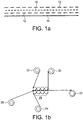
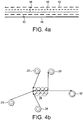
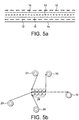
- figures 1a to 6a show schematic representations of cross-sections through lightning strike resistance laminates, each of which is manufactured by processes 1b to 6b respectively.
- Figures 1a , 2a and 3a are outside the invention while Figures 4a to 6a are according to the invention.
- Figure 1b is outside the invention while Figures 4b to 6b are according to the invention.
- the same numerals are used throughout the figures where the features are equivalent.
- the laminates comprise an expanded copper foil 10 constituting the metal component surrounded on both sides by layers of thermosetting resin 12 and backed on one side by backing paper 14.
- Figure 2a shows this arrangement with the addition of a polyester veil 16, constituting the substantially non-reshapable solid material, positioned on the side of the metal material facing away from the backing paper 14.
- Figure 3a shows the arrangement of Figure 2a but wherein no resin layer 12 is present on the backing paper side.
- Figure 4a shows the arrangement of Figure 2a but wherein the veil 16 is positioned between the metal material 10 and resin 12 and the backing sheet 14.
- Figures 5a and 6a show the arrangement of Figure 2a but wherein an additional veil has been positioned between the metal material 10 and resin 12 and the backing sheet 14.
- Figures 1b to 6b show a reel 20 of the expanded copper foil being fed through heated compaction rollers 28 and eventually rolled up onto wind up reel 32.
- Figure 2b the arrangement is the same as for Figure 1b except that reel 22 is replaced by reel 23 comprising the veil adhered to a layer of resin which in turn is adhered to backing paper.
- Figure 4b the arrangement is the same as for Figure 1b , except that reel 24 is replaced by reel 26 comprising the veil adhered to a layer of resin which in turn is adhered to backing paper.
- Figure 5b the arrangement is the same as for Figure 4b , wherein reel 22 is replaced by reel 23 comprising a second veil adhered to a layer of resin which in turn is adhered to backing paper.
- Figure 7 shows an image of the tool head 50 of an automated tape lay-up apparatus suitable for use in the present invention.
- the laminate 52 is fed to the deposition head 54 after being passed over roller 56.
- Deposition head 54 presses laminate 52 onto the surface of mold 58.
- the adhesion between the laminate 52 and mold 58 is greater than that between the laminate 52 and its backing paper 60 and so it remains adhered to the mold as the backing paper 60 detaches and is taken up on a roller (not shown).
Landscapes
- Engineering & Computer Science (AREA)
- Aviation & Aerospace Engineering (AREA)
- Laminated Bodies (AREA)
- Moulding By Coating Moulds (AREA)
- Casting Or Compression Moulding Of Plastics Or The Like (AREA)
- Shielding Devices Or Components To Electric Or Magnetic Fields (AREA)
Claims (16)
- Härtbares flexibles Laminat, das gegen elektromagnetische Gefahr widerstandsfähig ist, umfassend eine Schicht aus elektrisch leitfähigem Metallmaterial und duroplastisches Harz, wobei eine Außenfläche des Laminats eine ablösbare Rückseitenlage in Kontakt mit dem Harz umfasst, und wobei das Laminat des Weiteren eine poröse, im Wesentlichen nicht-umformbare Lage aus festem Material mit einem Gewicht pro Flächeneinheit von 5 bis 100 g/m2 (gsm) umfasst, das zwischen dem leitfähigen Metallmaterial und der Rückseitenlage positioniert ist, wobei "im Wesentlichen nicht-umformbar" bedeutet, dass die poröse Lage aus festem Material die Eigenschaft hat, dass es sich um weniger als 1,0 % längt, wenn ein Streifen des Materials, der 2,54 cm breit und 33,0 cm lang ist, an einem Ende aufgehängt wird und an dem anderen Ende 1 Minute lang eine Masse von 500 g befestigt und gleichmäßig daran verteilt wird, und das ausgewählt ist aus Glasfaser, Polyester und Nylon.
- Laminat nach Anspruch 1, das eine Harzschicht auf der Außenfläche umfasst, die durch die Rückseitenlage nicht bedeckt wird.
- Laminat nach einem der vorhergehenden Ansprüche, welches einen ununterbrochenen Pfad des Harzes durch die Dicke des Laminats hindurch umfasst.
- Laminat nach einem der vorhergehenden Ansprüche, wobei das leitfähige Metallmaterial in Lagenform vorliegt und porös ist, wobei das Metallmaterial vorzugsweise eine expandierte Metallfolie ist, die die Form eines Drahtmaschenmaterials annimmt.
- Laminat nach einem der vorhergehenden Ansprüche, wobei das Metallmaterial ein Gewicht pro Flächeneinheit von 50 bis 1500 gsm aufweist, und wobei das Gewicht pro Flächeneinheit des Laminats ohne das Metallelement kleiner als 800 gsm ist.
- Laminat nach einem der vorhergehenden Ansprüche, wobei das im Wesentlichen nicht-umformbare feste Material elektrisch isolierend ist.
- Laminat nach einem der vorhergehenden Ansprüche, wobei das Laminat eine zweite poröse, im Wesentlichen nicht-umformbare Lage aus festem Material mit einem Gewicht pro Flächeneinheit von 5 bis 100 g/m2 (gsm) umfasst, wobei mit "im Wesentlichen nicht-umformbar" gemeint ist, dass die zweite poröse Lage aus festem Material die Eigenschaft hat, dass es sich um weniger als 1,0 % längt, wenn ein Streifen des Materials, der 2,54 cm breit und 33,0 cm lang ist, an einem Ende aufgehängt wird und an dem anderen Ende 1 Minute lang eine Masse von 500 g befestigt und gleichmäßig daran verteilt wird, und das ausgewählt ist aus Glasfaser, Polyester und Nylon; wobei vorzugsweise eine Lage aus porösem, im Wesentlichen nicht-umformbarem, festem Material auf beiden Seiten des Metallmaterials positioniert ist.
- Laminat nach einem der vorhergehenden Ansprüche, wobei auf der Seite des Metallmaterials, die die Rückseitenlage nicht enthält, ein größerer Harzgehalt vorliegt als auf der Seite, die die Rückseitenlage enthält.
- Laminat nach einem der vorhergehenden Ansprüche, wobei das feste Material in Form von Glasfasertextil oder Glasfaserschleiern oder in Form von Polyesterisolierpolymeren oder Nylonisolierpolymeren vorliegt.
- Verfahren zur Fertigung eines Laminats mit elektromagnetischer Widerstandsfähigkeit gemäß einem der vorhergehenden Ansprüche, wobei das Verfahren kontinuierliches gemeinsames Einspeisen der Lage des elektrisch leitfähigen Metallmaterials und der porösen Lage des im Wesentlichen nicht-umformbaren, festen Materials und Bringen von zwei Lagen aus Rückseitenmaterial, von denen mindestens eine mit duroplastischem Harz beschichtet ist, in Kontakt mit den Außenflächen des Materials, danach Komprimieren der Lagen miteinander und dann Entfernen einer Lage aus Rückseitenmaterial umfasst.
- Verfahren nach Anspruch 10, wobei das Komprimieren der Lagen durchgeführt wird, indem die Lagen durch eine oder mehrere Rollen geführt wird.
- Verfahren nach einem von Anspruch 10 oder Anspruch 11, wobei die Lage des porösen, im Wesentlichen nicht-umformbaren, festen Materials an eine Harzbeschichtung gehaftet wird, mit der eine Lage des Rückseitenmaterials beschichtet ist.
- Verfahren nach Anspruch 12, wobei ein zweites poröses, im Wesentlichen nicht-umformbares, festes Material ebenfalls an eine Harzbeschichtung gehaftet wird, mit der die andere Lage des Rückseitenmaterials beschichtet ist, wobei mit "im Wesentlichen nicht-umformbar" gemeint ist, dass das zweite poröse feste Material die Eigenschaft hat, dass es sich um weniger als 1,0 % längt, wenn ein Streifen des Materials, der 2,54 cm breit und 33,0 cm lang ist, an einem Ende aufgehängt wird und an dem anderen Ende 1 Minute lang eine Masse von 500 g befestigt und gleichmäßig daran verteilt wird, und das ausgewählt ist aus Glasfaser, Polyester und Nylon.
- Verfahren zum Ablegen ("Lay-down") eines härtbaren flexiblen Laminats mit elektromagnetischer Widerstandsfähigkeit nach einem der Ansprüche 1 bis 9 auf einer Formoberfläche, wobei eine Außenfläche des Laminats eine ablösbare Rückseitenlage in Kontakt mit Harz umfasst, wobei das Laminat automatisch durch einen Werkzeugkopf von einer Rolle auf die Oberfläche der Form eingespeist wird, so dass eine Außenfläche des Laminats, die klebriges, härtbares, duroplastisches Harz umfasst, die Formoberfläche kontaktiert und das Laminat an der Formoberfläche haftet, wenn das Werkzeug das Laminat absetzt, und die Rückseitenschicht entfernt wird, wodurch das Laminat ohne seine Rückseitenlage in Position auf der Oberfläche der Form zurückgelassen wird.
- Verfahren nach Anspruch 14, dem der Schritt des Absetzens einer Anzahl von Prepregs, die Strukturfasern und duroplastisches Harz umfassen, auf der freiliegenden Oberfläche des abgesetzten Laminats folgt.
- Verfahren nach Anspruch 15, wobei die Anordnung gehärtet wird, indem sie erhöhter Temperatur und gegebenenfalls erhöhtem Druck ausgesetzt wird, um ein gehärtetes Laminat mit elektromagnetischer Widerstandsfähigkeit zu produzieren.
Applications Claiming Priority (2)
| Application Number | Priority Date | Filing Date | Title |
|---|---|---|---|
| GB0919085.1A GB2474897B (en) | 2009-11-02 | 2009-11-02 | Electromagnetic hazard protector for composite materials |
| PCT/GB2010/051758 WO2011051697A1 (en) | 2009-11-02 | 2010-10-19 | Electromagnetic hazard protector for composite materials |
Publications (2)
| Publication Number | Publication Date |
|---|---|
| EP2496410A1 EP2496410A1 (de) | 2012-09-12 |
| EP2496410B1 true EP2496410B1 (de) | 2019-04-24 |
Family
ID=41434946
Family Applications (1)
| Application Number | Title | Priority Date | Filing Date |
|---|---|---|---|
| EP10770867.9A Active EP2496410B1 (de) | 2009-11-02 | 2010-10-19 | Schutz vor elektromagnetischer gefahr für verbundstoffe |
Country Status (10)
| Country | Link |
|---|---|
| US (1) | US9051059B2 (de) |
| EP (1) | EP2496410B1 (de) |
| JP (1) | JP5837881B2 (de) |
| CN (1) | CN102712169B (de) |
| AU (1) | AU2010311191B2 (de) |
| BR (1) | BR112012011590B1 (de) |
| CA (1) | CA2778410C (de) |
| GB (1) | GB2474897B (de) |
| RU (1) | RU2546729C2 (de) |
| WO (1) | WO2011051697A1 (de) |
Families Citing this family (7)
| Publication number | Priority date | Publication date | Assignee | Title |
|---|---|---|---|---|
| GB2503864B (en) * | 2012-03-08 | 2014-09-03 | Hexcel Composites Ltd | Composite material for automated lay-up |
| FR2988639B1 (fr) | 2012-04-02 | 2014-06-13 | Hexcel Reinforcements | Materiau aux proprietes de conductivite ameliorees pour la realisation de pieces composites en association avec une resine |
| GB201522539D0 (en) * | 2015-12-21 | 2016-02-03 | Hexcel Composites Ltd | Improvements in or relating to electrically conducting materials |
| KR20180096687A (ko) * | 2015-12-22 | 2018-08-29 | 사이텍 인더스트리스 인코포레이티드 | 복합 부품용 몰드 이형성 표면 재료 |
| CN109789662A (zh) | 2016-09-27 | 2019-05-21 | 3M创新有限公司 | 保护膜 |
| CN107487034B (zh) * | 2017-08-23 | 2020-05-08 | 范晓宇 | 一种雷电防护金属网复合膜及其制备方法 |
| JP7511354B2 (ja) * | 2020-02-12 | 2024-07-05 | 三菱重工業株式会社 | 複合材料構造体 |
Family Cites Families (16)
| Publication number | Priority date | Publication date | Assignee | Title |
|---|---|---|---|---|
| US5151327A (en) * | 1990-03-15 | 1992-09-29 | Nitto Denko Corporation | Adhesive sheet for reinforcing thin rigid plates |
| US5370921A (en) * | 1991-07-11 | 1994-12-06 | The Dexter Corporation | Lightning strike composite and process |
| US5225265A (en) | 1991-12-06 | 1993-07-06 | Basf Aktiengesellschaft | Environmentally durable lightning strike protection materials for composite structures |
| DE10031510A1 (de) * | 2000-06-28 | 2002-01-17 | Airbus Gmbh | Strukturbauteil für ein Flugzeug |
| GB0122195D0 (en) | 2001-09-14 | 2001-10-31 | Hexcel Composites Ltd | Epoxy resin composition |
| US7093787B2 (en) * | 2003-04-28 | 2006-08-22 | United Technologies Corporation | Lightning strike mitigation system |
| WO2006011625A1 (ja) * | 2004-07-30 | 2006-02-02 | Mitsubishi Chemical Corporation | 吸液性複合体及びその製造方法、吸液性物品並びにノズル |
| US20060292375A1 (en) * | 2005-06-28 | 2006-12-28 | Martin Cary J | Resin compositions with high thermoplatic loading |
| US20070141927A1 (en) * | 2005-12-21 | 2007-06-21 | Brown Arlene M | Method and system for exterior protection of an aircraft |
| DE102006035847B4 (de) * | 2006-08-01 | 2009-11-19 | Airbus Deutschland Gmbh | Strukturanordnung sowie Verfahren zum Herstellen eines Bauteils für die Luft-und Raumfahrt |
| US7525785B2 (en) * | 2006-12-14 | 2009-04-28 | The Boeing Company | Lightning strike protection method and apparatus |
| US7628879B2 (en) * | 2007-08-23 | 2009-12-08 | The Boeing Company | Conductive scrim embedded structural adhesive films |
| JP5439387B2 (ja) * | 2008-02-18 | 2014-03-12 | ヘクセル コンポジット、リミテッド | 自動テープ敷設装置に使用する複合テープ |
| US8206823B2 (en) * | 2008-04-14 | 2012-06-26 | The Boeing Company | System and method for fabrication of integrated lightning strike protection material |
| GB2475041A (en) * | 2009-11-02 | 2011-05-11 | Hexcel Composites Ltd | Electromagnetic hazard protector for composite materials |
| EP2524680B1 (de) * | 2010-01-13 | 2015-05-06 | Sumitomo Seika Chemicals CO. LTD. | Wasserabsorbierende folienstruktur |
-
2009
- 2009-11-02 GB GB0919085.1A patent/GB2474897B/en not_active Expired - Fee Related
-
2010
- 2010-10-19 EP EP10770867.9A patent/EP2496410B1/de active Active
- 2010-10-19 CA CA2778410A patent/CA2778410C/en not_active Expired - Fee Related
- 2010-10-19 BR BR112012011590-1A patent/BR112012011590B1/pt not_active IP Right Cessation
- 2010-10-19 RU RU2012122790/05A patent/RU2546729C2/ru active
- 2010-10-19 US US13/504,966 patent/US9051059B2/en active Active
- 2010-10-19 AU AU2010311191A patent/AU2010311191B2/en active Active
- 2010-10-19 WO PCT/GB2010/051758 patent/WO2011051697A1/en not_active Ceased
- 2010-10-19 JP JP2012535928A patent/JP5837881B2/ja active Active
- 2010-10-19 CN CN201080060325.9A patent/CN102712169B/zh active Active
Non-Patent Citations (1)
| Title |
|---|
| None * |
Also Published As
| Publication number | Publication date |
|---|---|
| AU2010311191B2 (en) | 2014-05-29 |
| BR112012011590B1 (pt) | 2019-08-20 |
| EP2496410A1 (de) | 2012-09-12 |
| CA2778410C (en) | 2017-11-07 |
| CN102712169A (zh) | 2012-10-03 |
| GB2474897A (en) | 2011-05-04 |
| WO2011051697A1 (en) | 2011-05-05 |
| JP2013509315A (ja) | 2013-03-14 |
| AU2010311191A1 (en) | 2012-05-17 |
| US20120219775A1 (en) | 2012-08-30 |
| RU2546729C2 (ru) | 2015-04-10 |
| US9051059B2 (en) | 2015-06-09 |
| CN102712169B (zh) | 2015-08-05 |
| CA2778410A1 (en) | 2011-05-05 |
| BR112012011590A2 (pt) | 2016-06-28 |
| JP5837881B2 (ja) | 2015-12-24 |
| GB2474897B (en) | 2015-09-16 |
| GB0919085D0 (en) | 2009-12-16 |
| RU2012122790A (ru) | 2013-12-10 |
Similar Documents
| Publication | Publication Date | Title |
|---|---|---|
| EP2496411B1 (de) | Schutz vor elektromagnetischer gefahr für verbundstoffe | |
| EP2496410B1 (de) | Schutz vor elektromagnetischer gefahr für verbundstoffe | |
| US11014337B2 (en) | Laminate structures comprising fiber-reinforced thermoplastic prepreg plies | |
| EP2512800B1 (de) | Verfahren zur ausstattung von materialien zur herstellung von verbundartikeln mit leitfähigkeit und materialien dafür | |
| JP2018538172A5 (de) | ||
| EP2340163A1 (de) | Verbesserte verbdunstoffe | |
| EP3393769B1 (de) | Elektrisch leitende materialien, verfahren und verwendung | |
| CN110951100A (zh) | 一种树脂性能差异分布的自粘性阻燃预浸料的制备方法 | |
| KR102242544B1 (ko) | 회로 기판 제조용 연속 시트의 제조 방법 및 이로부터 제조된 회로 기판 제조용 연속 시트 | |
| EP3865272A1 (de) | Verfahren zur herstellung eines feuerbeständigen und hitzebeständigen vorimprägnierten fasermaterials | |
| KR102106117B1 (ko) | 회로 기판 제조용 연속 시트의 제조 방법 및 이로부터 제조된 회로 기판 제조용 연속 시트 | |
| EP4674613A2 (de) | Verbesserte unidirektionale prepregs |
Legal Events
| Date | Code | Title | Description |
|---|---|---|---|
| PUAI | Public reference made under article 153(3) epc to a published international application that has entered the european phase |
Free format text: ORIGINAL CODE: 0009012 |
|
| 17P | Request for examination filed |
Effective date: 20120518 |
|
| AK | Designated contracting states |
Kind code of ref document: A1 Designated state(s): AL AT BE BG CH CY CZ DE DK EE ES FI FR GB GR HR HU IE IS IT LI LT LU LV MC MK MT NL NO PL PT RO RS SE SI SK SM TR |
|
| DAX | Request for extension of the european patent (deleted) | ||
| 17Q | First examination report despatched |
Effective date: 20140127 |
|
| STAA | Information on the status of an ep patent application or granted ep patent |
Free format text: STATUS: EXAMINATION IS IN PROGRESS |
|
| GRAP | Despatch of communication of intention to grant a patent |
Free format text: ORIGINAL CODE: EPIDOSNIGR1 |
|
| STAA | Information on the status of an ep patent application or granted ep patent |
Free format text: STATUS: GRANT OF PATENT IS INTENDED |
|
| INTG | Intention to grant announced |
Effective date: 20181107 |
|
| GRAS | Grant fee paid |
Free format text: ORIGINAL CODE: EPIDOSNIGR3 |
|
| GRAA | (expected) grant |
Free format text: ORIGINAL CODE: 0009210 |
|
| STAA | Information on the status of an ep patent application or granted ep patent |
Free format text: STATUS: THE PATENT HAS BEEN GRANTED |
|
| RAP1 | Party data changed (applicant data changed or rights of an application transferred) |
Owner name: HEXCEL COMPOSITES LIMITED |
|
| AK | Designated contracting states |
Kind code of ref document: B1 Designated state(s): AL AT BE BG CH CY CZ DE DK EE ES FI FR GB GR HR HU IE IS IT LI LT LU LV MC MK MT NL NO PL PT RO RS SE SI SK SM TR |
|
| REG | Reference to a national code |
Ref country code: GB Ref legal event code: FG4D |
|
| REG | Reference to a national code |
Ref country code: CH Ref legal event code: EP |
|
| REG | Reference to a national code |
Ref country code: AT Ref legal event code: REF Ref document number: 1123655 Country of ref document: AT Kind code of ref document: T Effective date: 20190515 Ref country code: IE Ref legal event code: FG4D |
|
| REG | Reference to a national code |
Ref country code: DE Ref legal event code: R096 Ref document number: 602010058430 Country of ref document: DE |
|
| REG | Reference to a national code |
Ref country code: NL Ref legal event code: MP Effective date: 20190424 |
|
| REG | Reference to a national code |
Ref country code: LT Ref legal event code: MG4D |
|
| PG25 | Lapsed in a contracting state [announced via postgrant information from national office to epo] |
Ref country code: NL Free format text: LAPSE BECAUSE OF FAILURE TO SUBMIT A TRANSLATION OF THE DESCRIPTION OR TO PAY THE FEE WITHIN THE PRESCRIBED TIME-LIMIT Effective date: 20190424 |
|
| PG25 | Lapsed in a contracting state [announced via postgrant information from national office to epo] |
Ref country code: LT Free format text: LAPSE BECAUSE OF FAILURE TO SUBMIT A TRANSLATION OF THE DESCRIPTION OR TO PAY THE FEE WITHIN THE PRESCRIBED TIME-LIMIT Effective date: 20190424 Ref country code: HR Free format text: LAPSE BECAUSE OF FAILURE TO SUBMIT A TRANSLATION OF THE DESCRIPTION OR TO PAY THE FEE WITHIN THE PRESCRIBED TIME-LIMIT Effective date: 20190424 Ref country code: ES Free format text: LAPSE BECAUSE OF FAILURE TO SUBMIT A TRANSLATION OF THE DESCRIPTION OR TO PAY THE FEE WITHIN THE PRESCRIBED TIME-LIMIT Effective date: 20190424 Ref country code: SE Free format text: LAPSE BECAUSE OF FAILURE TO SUBMIT A TRANSLATION OF THE DESCRIPTION OR TO PAY THE FEE WITHIN THE PRESCRIBED TIME-LIMIT Effective date: 20190424 Ref country code: NO Free format text: LAPSE BECAUSE OF FAILURE TO SUBMIT A TRANSLATION OF THE DESCRIPTION OR TO PAY THE FEE WITHIN THE PRESCRIBED TIME-LIMIT Effective date: 20190724 Ref country code: FI Free format text: LAPSE BECAUSE OF FAILURE TO SUBMIT A TRANSLATION OF THE DESCRIPTION OR TO PAY THE FEE WITHIN THE PRESCRIBED TIME-LIMIT Effective date: 20190424 Ref country code: PT Free format text: LAPSE BECAUSE OF FAILURE TO SUBMIT A TRANSLATION OF THE DESCRIPTION OR TO PAY THE FEE WITHIN THE PRESCRIBED TIME-LIMIT Effective date: 20190824 Ref country code: AL Free format text: LAPSE BECAUSE OF FAILURE TO SUBMIT A TRANSLATION OF THE DESCRIPTION OR TO PAY THE FEE WITHIN THE PRESCRIBED TIME-LIMIT Effective date: 20190424 |
|
| PG25 | Lapsed in a contracting state [announced via postgrant information from national office to epo] |
Ref country code: BG Free format text: LAPSE BECAUSE OF FAILURE TO SUBMIT A TRANSLATION OF THE DESCRIPTION OR TO PAY THE FEE WITHIN THE PRESCRIBED TIME-LIMIT Effective date: 20190724 Ref country code: GR Free format text: LAPSE BECAUSE OF FAILURE TO SUBMIT A TRANSLATION OF THE DESCRIPTION OR TO PAY THE FEE WITHIN THE PRESCRIBED TIME-LIMIT Effective date: 20190725 Ref country code: PL Free format text: LAPSE BECAUSE OF FAILURE TO SUBMIT A TRANSLATION OF THE DESCRIPTION OR TO PAY THE FEE WITHIN THE PRESCRIBED TIME-LIMIT Effective date: 20190424 Ref country code: LV Free format text: LAPSE BECAUSE OF FAILURE TO SUBMIT A TRANSLATION OF THE DESCRIPTION OR TO PAY THE FEE WITHIN THE PRESCRIBED TIME-LIMIT Effective date: 20190424 Ref country code: RS Free format text: LAPSE BECAUSE OF FAILURE TO SUBMIT A TRANSLATION OF THE DESCRIPTION OR TO PAY THE FEE WITHIN THE PRESCRIBED TIME-LIMIT Effective date: 20190424 |
|
| REG | Reference to a national code |
Ref country code: AT Ref legal event code: MK05 Ref document number: 1123655 Country of ref document: AT Kind code of ref document: T Effective date: 20190424 |
|
| PG25 | Lapsed in a contracting state [announced via postgrant information from national office to epo] |
Ref country code: IS Free format text: LAPSE BECAUSE OF FAILURE TO SUBMIT A TRANSLATION OF THE DESCRIPTION OR TO PAY THE FEE WITHIN THE PRESCRIBED TIME-LIMIT Effective date: 20190824 |
|
| REG | Reference to a national code |
Ref country code: DE Ref legal event code: R097 Ref document number: 602010058430 Country of ref document: DE |
|
| PG25 | Lapsed in a contracting state [announced via postgrant information from national office to epo] |
Ref country code: EE Free format text: LAPSE BECAUSE OF FAILURE TO SUBMIT A TRANSLATION OF THE DESCRIPTION OR TO PAY THE FEE WITHIN THE PRESCRIBED TIME-LIMIT Effective date: 20190424 Ref country code: SK Free format text: LAPSE BECAUSE OF FAILURE TO SUBMIT A TRANSLATION OF THE DESCRIPTION OR TO PAY THE FEE WITHIN THE PRESCRIBED TIME-LIMIT Effective date: 20190424 Ref country code: RO Free format text: LAPSE BECAUSE OF FAILURE TO SUBMIT A TRANSLATION OF THE DESCRIPTION OR TO PAY THE FEE WITHIN THE PRESCRIBED TIME-LIMIT Effective date: 20190424 Ref country code: CZ Free format text: LAPSE BECAUSE OF FAILURE TO SUBMIT A TRANSLATION OF THE DESCRIPTION OR TO PAY THE FEE WITHIN THE PRESCRIBED TIME-LIMIT Effective date: 20190424 Ref country code: AT Free format text: LAPSE BECAUSE OF FAILURE TO SUBMIT A TRANSLATION OF THE DESCRIPTION OR TO PAY THE FEE WITHIN THE PRESCRIBED TIME-LIMIT Effective date: 20190424 Ref country code: DK Free format text: LAPSE BECAUSE OF FAILURE TO SUBMIT A TRANSLATION OF THE DESCRIPTION OR TO PAY THE FEE WITHIN THE PRESCRIBED TIME-LIMIT Effective date: 20190424 |
|
| PG25 | Lapsed in a contracting state [announced via postgrant information from national office to epo] |
Ref country code: SM Free format text: LAPSE BECAUSE OF FAILURE TO SUBMIT A TRANSLATION OF THE DESCRIPTION OR TO PAY THE FEE WITHIN THE PRESCRIBED TIME-LIMIT Effective date: 20190424 Ref country code: IT Free format text: LAPSE BECAUSE OF FAILURE TO SUBMIT A TRANSLATION OF THE DESCRIPTION OR TO PAY THE FEE WITHIN THE PRESCRIBED TIME-LIMIT Effective date: 20190424 |
|
| PLBE | No opposition filed within time limit |
Free format text: ORIGINAL CODE: 0009261 |
|
| STAA | Information on the status of an ep patent application or granted ep patent |
Free format text: STATUS: NO OPPOSITION FILED WITHIN TIME LIMIT |
|
| PG25 | Lapsed in a contracting state [announced via postgrant information from national office to epo] |
Ref country code: TR Free format text: LAPSE BECAUSE OF FAILURE TO SUBMIT A TRANSLATION OF THE DESCRIPTION OR TO PAY THE FEE WITHIN THE PRESCRIBED TIME-LIMIT Effective date: 20190424 |
|
| 26N | No opposition filed |
Effective date: 20200127 |
|
| PGFP | Annual fee paid to national office [announced via postgrant information from national office to epo] |
Ref country code: GB Payment date: 20191018 Year of fee payment: 10 |
|
| PG25 | Lapsed in a contracting state [announced via postgrant information from national office to epo] |
Ref country code: MC Free format text: LAPSE BECAUSE OF FAILURE TO SUBMIT A TRANSLATION OF THE DESCRIPTION OR TO PAY THE FEE WITHIN THE PRESCRIBED TIME-LIMIT Effective date: 20190424 Ref country code: SI Free format text: LAPSE BECAUSE OF FAILURE TO SUBMIT A TRANSLATION OF THE DESCRIPTION OR TO PAY THE FEE WITHIN THE PRESCRIBED TIME-LIMIT Effective date: 20190424 |
|
| REG | Reference to a national code |
Ref country code: CH Ref legal event code: PL |
|
| PG25 | Lapsed in a contracting state [announced via postgrant information from national office to epo] |
Ref country code: LI Free format text: LAPSE BECAUSE OF NON-PAYMENT OF DUE FEES Effective date: 20191031 Ref country code: LU Free format text: LAPSE BECAUSE OF NON-PAYMENT OF DUE FEES Effective date: 20191019 Ref country code: CH Free format text: LAPSE BECAUSE OF NON-PAYMENT OF DUE FEES Effective date: 20191031 |
|
| REG | Reference to a national code |
Ref country code: BE Ref legal event code: MM Effective date: 20191031 |
|
| PG25 | Lapsed in a contracting state [announced via postgrant information from national office to epo] |
Ref country code: BE Free format text: LAPSE BECAUSE OF NON-PAYMENT OF DUE FEES Effective date: 20191031 |
|
| PG25 | Lapsed in a contracting state [announced via postgrant information from national office to epo] |
Ref country code: IE Free format text: LAPSE BECAUSE OF NON-PAYMENT OF DUE FEES Effective date: 20191019 |
|
| PG25 | Lapsed in a contracting state [announced via postgrant information from national office to epo] |
Ref country code: CY Free format text: LAPSE BECAUSE OF FAILURE TO SUBMIT A TRANSLATION OF THE DESCRIPTION OR TO PAY THE FEE WITHIN THE PRESCRIBED TIME-LIMIT Effective date: 20190424 |
|
| GBPC | Gb: european patent ceased through non-payment of renewal fee |
Effective date: 20201019 |
|
| PG25 | Lapsed in a contracting state [announced via postgrant information from national office to epo] |
Ref country code: HU Free format text: LAPSE BECAUSE OF FAILURE TO SUBMIT A TRANSLATION OF THE DESCRIPTION OR TO PAY THE FEE WITHIN THE PRESCRIBED TIME-LIMIT; INVALID AB INITIO Effective date: 20101019 Ref country code: MT Free format text: LAPSE BECAUSE OF FAILURE TO SUBMIT A TRANSLATION OF THE DESCRIPTION OR TO PAY THE FEE WITHIN THE PRESCRIBED TIME-LIMIT Effective date: 20190424 |
|
| PG25 | Lapsed in a contracting state [announced via postgrant information from national office to epo] |
Ref country code: GB Free format text: LAPSE BECAUSE OF NON-PAYMENT OF DUE FEES Effective date: 20201019 |
|
| PG25 | Lapsed in a contracting state [announced via postgrant information from national office to epo] |
Ref country code: MK Free format text: LAPSE BECAUSE OF FAILURE TO SUBMIT A TRANSLATION OF THE DESCRIPTION OR TO PAY THE FEE WITHIN THE PRESCRIBED TIME-LIMIT Effective date: 20190424 |
|
| P01 | Opt-out of the competence of the unified patent court (upc) registered |
Effective date: 20230530 |
|
| PGFP | Annual fee paid to national office [announced via postgrant information from national office to epo] |
Ref country code: FR Payment date: 20250908 Year of fee payment: 16 |
|
| PGFP | Annual fee paid to national office [announced via postgrant information from national office to epo] |
Ref country code: DE Payment date: 20250902 Year of fee payment: 16 |