EP2496514B1 - Wasserhahnanordnung - Google Patents
Wasserhahnanordnung Download PDFInfo
- Publication number
- EP2496514B1 EP2496514B1 EP10776492.0A EP10776492A EP2496514B1 EP 2496514 B1 EP2496514 B1 EP 2496514B1 EP 10776492 A EP10776492 A EP 10776492A EP 2496514 B1 EP2496514 B1 EP 2496514B1
- Authority
- EP
- European Patent Office
- Prior art keywords
- tap assembly
- projection
- actuation member
- cover
- tap
- Prior art date
- Legal status (The legal status is an assumption and is not a legal conclusion. Google has not performed a legal analysis and makes no representation as to the accuracy of the status listed.)
- Active
Links
Images


Classifications
-
- B—PERFORMING OPERATIONS; TRANSPORTING
- B67—OPENING, CLOSING OR CLEANING BOTTLES, JARS OR SIMILAR CONTAINERS; LIQUID HANDLING
- B67D—DISPENSING, DELIVERING OR TRANSFERRING LIQUIDS, NOT OTHERWISE PROVIDED FOR
- B67D3/00—Apparatus or devices for controlling flow of liquids under gravity from storage containers for dispensing purposes
- B67D3/04—Liquid-dispensing taps or cocks adapted to seal and open tapping holes of casks, e.g. for beer
- B67D3/045—Liquid-dispensing taps or cocks adapted to seal and open tapping holes of casks, e.g. for beer with a closing element having a linear movement, in a direction parallel to the seat
-
- B—PERFORMING OPERATIONS; TRANSPORTING
- B67—OPENING, CLOSING OR CLEANING BOTTLES, JARS OR SIMILAR CONTAINERS; LIQUID HANDLING
- B67B—APPLYING CLOSURE MEMBERS TO BOTTLES JARS, OR SIMILAR CONTAINERS; OPENING CLOSED CONTAINERS
- B67B7/00—Hand- or power-operated devices for opening closed containers
- B67B7/24—Hole-piercing devices
- B67B7/26—Hole-piercing devices combined with spouts
-
- B—PERFORMING OPERATIONS; TRANSPORTING
- B67—OPENING, CLOSING OR CLEANING BOTTLES, JARS OR SIMILAR CONTAINERS; LIQUID HANDLING
- B67D—DISPENSING, DELIVERING OR TRANSFERRING LIQUIDS, NOT OTHERWISE PROVIDED FOR
- B67D1/00—Apparatus or devices for dispensing beverages on draught
- B67D1/0042—Details of specific parts of the dispensers
- B67D1/0081—Dispensing valves
- B67D2001/0087—Dispensing valves being mounted on the dispenser housing
- B67D2001/0088—Dispensing valves being mounted on the dispenser housing operated by push buttons
Definitions
- a disadvantage with known fluid dispensing taps is release of the tap due to a pressure differential between the inside of the tap attached to a fluid container and the outside atmospheric pressure.
- Sterility of manufactured taps is obtained during the tap manufacture using processes such as steam autoclaving at temperatures above 100°C. Such treatment can frequently result in an internal vacuum being created. This can result in inadvertent actuation of the tap and unwanted and potentially hazardous spillage of fluid from the tap.
- One solution to this problem is to increase the force required to release the tap by the user by increasing tolerances between a tap body and an actuation member of the tap or by biasing actuation of the tap. However this can be inconvenient or potentially hazardous to the user.
- a further disadvantage with known taps is the risk of reaction of oxygen sensitive fluids, such as wine, with oxygen during transportation and/or storage of fluid within the fluid container to which the tap is attached before use of the tap. Such reaction can spoil the fluid and reduce shelf-life.
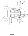
- the tap assembly 1 comprises a body 2 having a bore 3 formed therein (best seen in Figure 2 ) for flowable material such as fluids to flow through the tap assembly 1 from a connected fluid container (not shown) and exit the body 2 at an outlet 100 (as shown in Figure 1 ).
- the body 2 is formed in a plastics material by injection moulding.
- the tap assembly 1 also comprises an actuation member in the form of button 4A on the end of a push rod 4 to control movement of the push rod 4 which is configured to cover the bore 3 and thereby control the flow of fluid through the outlet 100.
- the button 4A is connected to the body 2 at seal 5 (as shown in Figure 2 ) via a second engagement portion in the form of annular groove 4B on button 4A engaging with corresponding annular bead 5A on seal 5. In this way aseptic conditions are maintained inside the tap assembly 1 during actuation of the button 4A.
- a pair of wing-like projections 6 extends from the body 2 near the button 4A to provide convenient surfaces, transverse to the body, for an operator to grip with their index and middle fingers while depressing the button 4A with their thumb.
- the tap assembly 1 also comprises a cover in the form of a cap 7 which encloses and abuts the button 4A to prevent actuation of the button 4A.
- Cap 7 is fitted by clip-fit engagement with annular lip 8 on body 2.
- the cap 7 attaches to a first engagement portion in the form of lip 8 of the body 2 at groove 9 (best seen in Figure 3D ) which aseptically seals to the body 2 via a seal surface 10.
- an internal pressure differential such as a vacuum within the tap assembly 1.
- the cap 7 connects to the upper periphery of the button 4A by clip-fit engagement of annular bead 11 with retainer groove 200 of cap 7 which retains the button-valve 4A with respect to the cap 7.
- the cap 7 has a pull tab 12 to facilitate a user gripping the cap 7 (best seen in Figures 3A-D) .
- the pull-tab 12 comprising ring 12A connected to the cap 7 at lug 12B (as shown in Figures 3A to 3C ).
- Indicative markings 12C on the pull-tab 12 indicate the need to remove the cap 7 before operation of the tap assembly 1.
- the pull tab 12 is connected to cap 7 via breakaway flap 13.
- the breakaway flap 13 is connected to the rest of the cap 7 by two weakened joins 14 extending substantially the profile of the cap 7 but ending proximal to the base 7A of the cap 7 (best seen in Figure 3A ).
- Figures 3A to C show the method of removal of the cap 7 from the body 2 of the tap assembly 1.
- a user 500 grips the ring 12A of the pull-tab 12 and pulls forward and away from the container (not shown) in the direction of arrow A (as shown in Figures 3A ).
- the pull-tab 12 (and connected breakaway flap 13) is then pulled upward to tear the weakened joins 14 (as shown in Figure 3B ).
- the breakaway flap 13 continues to tear away from the remainder of the cap 7 at the weakened joins 14 (as shown in Figures 3C ).
- the cap 7 then is pulled away from the body 3 of the tap assembly 1 in one piece which removes the breakaway flap 13 from part of the periphery of the cap 7 and allows the cap 7 to flex as required to remove bead 11 from groove 200 on button 4A. In this way the cap 7 provides a tamper evident feature to a user.
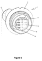
- the tap assembly 1 may also comprises a pierce-able sterility membrane 15 attached over the end of the bore 3.
- the sterility membrane 15 may be made of any suitable material which provides a barrier to the exchange of fluids between a fluid container (not shown) and the bore 3 (which improves the quality of oxygen sensitive fluids such as wine to improve the shelf life of the fluid during transport and storage and before use of the fluid container, such as a "bagin-the box"), and is attached to the end of the bore 3 by any suitable process known to those skilled in the art, such as heat sealing.
- a sterility membrane 15 can also provide a further barrier to microorganisms.
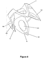
- the push-rod 4 of the tap assembly 1 also incorporates three projections 16 positioned on an end of the push-rod 4 and proximal to the sterility membrane 15. Actuation of the push-rod 4 via the button 4A causes piercing of the sterility membrane 15 by the projections 16 and resultant flow of fluid from the attached fluid container (not shown) once the projections 16 are withdrawn by release of the button 4.
- one of the projections (16A in Figures 8 and 9) is positioned forward of the other projections 16 with the result that actuation of the push-rod 4 causes piercing of the sterility membrane 15 by the projection 16A first (as shown in figures 6 and 7 ).
- projection 16A provides an initial point of entry into the sterility membrane 15 and minimises the force required to pierce the sterility membrane 15 by the push-rod 4.
- Each projection 16 comprises a shear wall 16A, a tapered surface 16B, a piercing point 16C and an aperture 16D (best seen in Figure 8 ).
- the combination of these features function as fluid entry ports 16E for fluid flow after the projections 16 have pierced the sterility membrane 15.
- This shape prevents occlusion of the side entry ports 16E by flaps of the sterility membrane 15 after piercing.
- the shape of the projections is configured to pull away the cut sterility membrane 15 from the intended fluid flow path in the bore 3 in the event of withdrawal of the projections 16 from the pierced sterility membrane 15.
- the base 17 may be connected to the push-rod 4 or may form an extension of the push-rod 4.
- Each projection can optionally include at least one serration (not shown) configured to maintain the projections 16 in place relative to the sterility membrane 15 after entry of the projections 16 into the sterility membrane 15 which aids in the cutting efficiency of the projections 16.
Landscapes
- Engineering & Computer Science (AREA)
- Mechanical Engineering (AREA)
- Closures For Containers (AREA)
Claims (15)
- Hahnanordnung, die Folgendes umfasst:einen Körper (2), der eine darin ausgebildete Bohrung (3) und einen ersten Eingriffsabschnitt (8) umfasst;ein Betätigungsglied (4A), das dazu konfiguriert ist, mindestens einen Abschnitt der Bohrung (3) zu bedecken;eine Abdeckung (7), die dazu konfiguriert ist, einen proximalen Abschnitt des Betätigungsglieds (4A) im Wesentlichen zu umschließen und daran anzuliegen, und einen zweiten Eingriffsabschnitt (9) umfasst, der zum Eingriff mit dem ersten Eingriffsabschnitt (8) konfiguriert ist, um eine Bewegung der Abdeckung (7) bezüglich des Körpers (2) zu verhindern;dadurch gekennzeichnet, dass der proximale Abschnitt des Betätigungsglieds (4A) einen ersten Halteabschnitt (200) umfasst und die Abdeckung (7) ferner einen zweiten Halteabschnitt (11) umfasst, der an einer Innenfläche der Abdeckung positioniert und zum Eingriff mit dem ersten Halteabschnitt (200) zur Verhinderung einer Bewegung des Betätigungsglieds (4A) bezüglich der Abdeckung konfiguriert ist;wobei die Hahnanordnung ferner Folgendes umfasst:eine Sterilmembran (15), die über ein Ende der Bohrung (3) abdichtend positioniert ist; undeinen Durchstecher (4), der dazu konfiguriert ist, die Sterilmembran (15) zu durchstechen, wenn das Betätigungsglied (4A) zum ersten Mal betätigt wird.
- Hahnanordnung nach Anspruch 1, wobei der erste Eingriffsabschnitt (8) eine ringförmige Lippe ist.
- Hahnanordnung nach Anspruch 2, wobei der zweite Eingriffsabschnitt (9) eine ringförmige Nut ist.
- Hahnanordnung nach einem der Ansprüche 1 bis 3, wobei der erste Eingriffsabschnitt (8) eine Dichtungsfläche (10) umfasst, die dazu konfiguriert ist, gegen Fluidverlust zwischen dem Körper (2) und dem Betätigungsglied (4A) aseptisch abzudichten.
- Hahnanordnung nach einem der Ansprüche 1 bis 4, wobei der proximale Abschnitt des Betätigungsglieds (4A) ein Knopf ist.
- Hahnanordnung nach einem der Ansprüche 1 bis 5, wobei der erste Halteabschnitt (200) eine ringförmige Nut ist.
- Hahnanordnung nach Anspruch 6, wobei der zweite Halteabschnitt (11) eine ringförmige Lippe ist, die zum Eingriff mit der an dem Betätigungsglied (4A) ausgebildeten ringförmigen Nut (200) konfiguriert ist.
- Hahnanordnung nach einem der Ansprüche 1 bis 7, wobei die Abdeckung (7) einen Manipulationsanzeiger umfasst, der einen entfernbaren Abschnitt (13) umfasst, der an mindestens einer geschwächten Verbindungsstelle (14) an der Abdeckung (7) befestigt ist.
- Hahnanordnung nach Anspruch 8, wobei der entfernbare Abschnitt eine Zuglasche (12) umfasst.
- Hahnanordnung nach Anspruch 1, wobei der Durchstecher (4) mindestens einen Vorsprung (16) umfasst, der an einem Ende des Betätigungsglieds (4A) proximal zur Sterilmembran (15) positioniert ist.
- Hahnanordnung nach Anspruch 10, wobei der mindestens eine Vorsprung (16) 3 bis 5 Vorsprünge umfasst.
- Hahnanordnung nach Anspruch 10 oder 11, wobei einer der Vorsprünge (16) bezüglich der Sterilmembran (15) zu den anderen Vorsprüngen (16) proximal positioniert ist.
- Hahnanordnung nach einem der Ansprüche 10 bis 12, wobei der mindestens eine Vorsprung (16) mindestens einen Fluiddurchgang umfasst, um den Fluidstrom zwischen der Bohrung (3) und der Hahnanordnung nach dem Eindringen des mindestens einen Vorsprungs (16) in die Sterilmembran (15) zu ermöglichen.
- Hahnanordnung nach einem der Ansprüche 10 bis 13, wobei der mindestens eine Vorsprung (16) mindestens eine Zackung umfasst, die dazu konfiguriert ist, nach dem Eindringen des Vorsprungs in die Sterilmembran den Vorsprung bezüglich der Sterilmembran (15) in Position zu halten.
- Hahnanordnung nach einem der Ansprüche 10 bis 14, wobei der mindestens eine Vorsprung (16) dazu konfiguriert ist, nach dem Zurückziehen des mindestens einen Vorsprungs von der Sterilmembran die durchtrennte Sterilmembran (15) vom vorgesehenen Fluidströmungsweg weg zu ziehen.
Applications Claiming Priority (2)
| Application Number | Priority Date | Filing Date | Title |
|---|---|---|---|
| US25729709P | 2009-11-02 | 2009-11-02 | |
| PCT/US2010/054973 WO2011162788A1 (en) | 2009-11-02 | 2010-11-01 | Tap assembly |
Publications (2)
| Publication Number | Publication Date |
|---|---|
| EP2496514A1 EP2496514A1 (de) | 2012-09-12 |
| EP2496514B1 true EP2496514B1 (de) | 2013-09-11 |
Family
ID=43431843
Family Applications (1)
| Application Number | Title | Priority Date | Filing Date |
|---|---|---|---|
| EP10776492.0A Active EP2496514B1 (de) | 2009-11-02 | 2010-11-01 | Wasserhahnanordnung |
Country Status (4)
| Country | Link |
|---|---|
| US (1) | US8561846B2 (de) |
| EP (1) | EP2496514B1 (de) |
| AU (1) | AU2010356074B2 (de) |
| WO (1) | WO2011162788A1 (de) |
Families Citing this family (15)
| Publication number | Priority date | Publication date | Assignee | Title |
|---|---|---|---|---|
| MX2016004623A (es) | 2013-10-11 | 2016-10-28 | Gehl Foods Llc | Dispensador de productos alimenticios y valvula. |
| PT3145856T (pt) * | 2014-05-23 | 2019-05-09 | David S Smith America Inc Dba Worldwide Dispensers | Dispensador de líquido com válvula |
| CA161168S (en) | 2014-08-29 | 2015-12-01 | Gehl Foods Inc | Valve |
| USD792164S1 (en) | 2014-08-29 | 2017-07-18 | Gehl Foods, Llc | Food dispenser |
| EP3185727A4 (de) | 2014-08-29 | 2018-08-22 | Gehl Foods, LLC | Lebensmittelproduktspender und ventil |
| USD718621S1 (en) | 2014-08-29 | 2014-12-02 | Gehl Foods, Inc. | Fitment for interconnection between product packaging and a product dispenser |
| USD795029S1 (en) | 2015-08-28 | 2017-08-22 | Gehl Foods, Llc | Tool |
| USD798106S1 (en) | 2015-08-28 | 2017-09-26 | Gehl Foods, Llc | Valve |
| GB201600894D0 (en) * | 2016-01-18 | 2016-03-02 | Obrist Closures Switzerland | Dispensing closure |
| US10280062B2 (en) * | 2016-10-20 | 2019-05-07 | Fres-Co System Usa, Inc. | Pierce at first use dispensing tap for flexible bag with filling gland and bag including the same |
| MX2019008514A (es) * | 2017-01-18 | 2019-09-18 | Obrist Closures Switzerland | Grifo de dispensacion de liquido. |
| JP2020528034A (ja) * | 2017-07-14 | 2020-09-17 | モントフォート ソリューションズ ゲー・エム・ベー・ハーMONTFORT Solutions GmbH | 標準カプセルを備えた容器クロージャ |
| ES2983588T3 (es) * | 2018-11-23 | 2024-10-23 | K Fresh Co Ltd | Conjunto para acceder a agua de coco en cocos |
| ES2890474B2 (es) * | 2020-07-07 | 2022-05-25 | Ortega Hernandez Felipe | Envase bolsa en caja para el almacenamiento y transporte de líquidos, con grifo de máxima seguridad para consumo directo o a través de tubos flexibles |
| EP4241828A1 (de) * | 2022-03-10 | 2023-09-13 | Fresenius Medical Care Deutschland GmbH | Verschlusselement für eine fluidleitung |
Family Cites Families (11)
| Publication number | Priority date | Publication date | Assignee | Title |
|---|---|---|---|---|
| DE3071897D1 (en) * | 1980-02-27 | 1987-03-05 | William C Christine | Combined piercer and valve for flexible bag |
| DE3124373A1 (de) * | 1980-06-24 | 1982-07-15 | A.C.I. Operations Pty. Ltd., Melbourne, Victoria | Hahnanordnung fuer einen behaelter |
| ATE9675T1 (de) | 1980-07-03 | 1984-10-15 | Wrightcel Ltd. | Hahn. |
| US4469249A (en) * | 1980-12-04 | 1984-09-04 | Diemoulders Proprietary Limited | Apparatus for dispensing liquids |
| US4570826A (en) * | 1983-03-31 | 1986-02-18 | The Rel Corporation | Dispenser closure |
| CA1234783A (en) * | 1984-09-28 | 1988-04-05 | David J. Van Dal | Dispensing valve |
| BE1000760A6 (fr) * | 1987-07-27 | 1989-03-28 | Lynes Holding Sa | Dispositif de bouchon verseur. |
| FR2619612A1 (fr) | 1987-08-19 | 1989-02-24 | Dufrene Alain | Robinet de soutirage de liquides |
| US5482176A (en) * | 1994-03-16 | 1996-01-09 | The West Company, Incorporated | Membrane piercing closure and spout assembly |
| JP5336192B2 (ja) * | 2005-11-11 | 2013-11-06 | アイティーダブリュ ニュージーランド リミティド | 流動性材料用の弁およびその閉鎖手段 |
| US7708164B2 (en) * | 2006-11-06 | 2010-05-04 | Fres-Co System Usa, Inc. | Volumetric dispensing fitment and package including the same |
-
2010
- 2010-11-01 WO PCT/US2010/054973 patent/WO2011162788A1/en not_active Ceased
- 2010-11-01 AU AU2010356074A patent/AU2010356074B2/en active Active
- 2010-11-01 EP EP10776492.0A patent/EP2496514B1/de active Active
- 2010-11-01 US US13/505,319 patent/US8561846B2/en active Active
Also Published As
| Publication number | Publication date |
|---|---|
| WO2011162788A1 (en) | 2011-12-29 |
| AU2010356074A1 (en) | 2012-05-24 |
| EP2496514A1 (de) | 2012-09-12 |
| AU2010356074B2 (en) | 2015-09-03 |
| US8561846B2 (en) | 2013-10-22 |
| US20120211519A1 (en) | 2012-08-23 |
Similar Documents
| Publication | Publication Date | Title |
|---|---|---|
| EP2496514B1 (de) | Wasserhahnanordnung | |
| EP1996505B1 (de) | Durchstossbare kappe und lochwerkzeug | |
| EP0686122B1 (de) | Verschluss für medizinbehälter | |
| US8967430B2 (en) | Tap assembly | |
| US6971548B2 (en) | Puncturable spout | |
| EP3048064B1 (de) | Durchstechbaugruppe für flexiblen behälter und flexibler behälter | |
| US20070102446A1 (en) | Blow fill sealed container with twist off top operated by overcap and method of making the same | |
| EP4240688B1 (de) | Durchstechkappe und durchstecher | |
| EP2238041B1 (de) | Verschluss | |
| CN101516762A (zh) | 一种穿孔设备组件 | |
| WO2001094213A3 (en) | A nozzle assemby with a reusable break-of cap and container having such nozzle assembly | |
| US20100096355A1 (en) | Lever type easy pull crown cap | |
| EP0686123B1 (de) | Kappe für medizinische flaschen | |
| US20180362210A1 (en) | Can end for user-friendly reclosing can | |
| AU2022240495B2 (en) | Pierceable closure valve assembly | |
| EP3145856B2 (de) | Flüssigkeitsspender mit ventil | |
| US10118746B2 (en) | Topper for a container | |
| US20250177249A1 (en) | Closure system for a drug container, and drug container comprising a closure system | |
| JP4898007B2 (ja) | 容器用のキャップ | |
| JP6325713B2 (ja) | ココナツを提供する方法及びココナツ製品 | |
| NZ584742A (en) | Tap assembly | |
| EP3089922A1 (de) | Stopfen für einen behälter |
Legal Events
| Date | Code | Title | Description |
|---|---|---|---|
| PUAI | Public reference made under article 153(3) epc to a published international application that has entered the european phase |
Free format text: ORIGINAL CODE: 0009012 |
|
| 17P | Request for examination filed |
Effective date: 20120425 |
|
| AK | Designated contracting states |
Kind code of ref document: A1 Designated state(s): AL AT BE BG CH CY CZ DE DK EE ES FI FR GB GR HR HU IE IS IT LI LT LU LV MC MK MT NL NO PL PT RO RS SE SI SK SM TR |
|
| DAX | Request for extension of the european patent (deleted) | ||
| GRAP | Despatch of communication of intention to grant a patent |
Free format text: ORIGINAL CODE: EPIDOSNIGR1 |
|
| INTG | Intention to grant announced |
Effective date: 20130517 |
|
| GRAS | Grant fee paid |
Free format text: ORIGINAL CODE: EPIDOSNIGR3 |
|
| GRAA | (expected) grant |
Free format text: ORIGINAL CODE: 0009210 |
|
| AK | Designated contracting states |
Kind code of ref document: B1 Designated state(s): AL AT BE BG CH CY CZ DE DK EE ES FI FR GB GR HR HU IE IS IT LI LT LU LV MC MK MT NL NO PL PT RO RS SE SI SK SM TR |
|
| REG | Reference to a national code |
Ref country code: GB Ref legal event code: FG4D |
|
| REG | Reference to a national code |
Ref country code: CH Ref legal event code: EP |
|
| REG | Reference to a national code |
Ref country code: AT Ref legal event code: REF Ref document number: 631508 Country of ref document: AT Kind code of ref document: T Effective date: 20130915 |
|
| REG | Reference to a national code |
Ref country code: IE Ref legal event code: FG4D |
|
| REG | Reference to a national code |
Ref country code: DE Ref legal event code: R096 Ref document number: 602010010259 Country of ref document: DE Effective date: 20131107 |
|
| PG25 | Lapsed in a contracting state [announced via postgrant information from national office to epo] |
Ref country code: SE Free format text: LAPSE BECAUSE OF FAILURE TO SUBMIT A TRANSLATION OF THE DESCRIPTION OR TO PAY THE FEE WITHIN THE PRESCRIBED TIME-LIMIT Effective date: 20130911 Ref country code: HR Free format text: LAPSE BECAUSE OF FAILURE TO SUBMIT A TRANSLATION OF THE DESCRIPTION OR TO PAY THE FEE WITHIN THE PRESCRIBED TIME-LIMIT Effective date: 20130911 Ref country code: NO Free format text: LAPSE BECAUSE OF FAILURE TO SUBMIT A TRANSLATION OF THE DESCRIPTION OR TO PAY THE FEE WITHIN THE PRESCRIBED TIME-LIMIT Effective date: 20131211 Ref country code: LT Free format text: LAPSE BECAUSE OF FAILURE TO SUBMIT A TRANSLATION OF THE DESCRIPTION OR TO PAY THE FEE WITHIN THE PRESCRIBED TIME-LIMIT Effective date: 20130911 Ref country code: CY Free format text: LAPSE BECAUSE OF FAILURE TO SUBMIT A TRANSLATION OF THE DESCRIPTION OR TO PAY THE FEE WITHIN THE PRESCRIBED TIME-LIMIT Effective date: 20130911 |
|
| REG | Reference to a national code |
Ref country code: NL Ref legal event code: VDEP Effective date: 20130911 |
|
| REG | Reference to a national code |
Ref country code: AT Ref legal event code: MK05 Ref document number: 631508 Country of ref document: AT Kind code of ref document: T Effective date: 20130911 |
|
| REG | Reference to a national code |
Ref country code: LT Ref legal event code: MG4D |
|
| PG25 | Lapsed in a contracting state [announced via postgrant information from national office to epo] |
Ref country code: SI Free format text: LAPSE BECAUSE OF FAILURE TO SUBMIT A TRANSLATION OF THE DESCRIPTION OR TO PAY THE FEE WITHIN THE PRESCRIBED TIME-LIMIT Effective date: 20130911 Ref country code: FI Free format text: LAPSE BECAUSE OF FAILURE TO SUBMIT A TRANSLATION OF THE DESCRIPTION OR TO PAY THE FEE WITHIN THE PRESCRIBED TIME-LIMIT Effective date: 20130911 Ref country code: GR Free format text: LAPSE BECAUSE OF FAILURE TO SUBMIT A TRANSLATION OF THE DESCRIPTION OR TO PAY THE FEE WITHIN THE PRESCRIBED TIME-LIMIT Effective date: 20131212 Ref country code: LV Free format text: LAPSE BECAUSE OF FAILURE TO SUBMIT A TRANSLATION OF THE DESCRIPTION OR TO PAY THE FEE WITHIN THE PRESCRIBED TIME-LIMIT Effective date: 20130911 |
|
| PG25 | Lapsed in a contracting state [announced via postgrant information from national office to epo] |
Ref country code: BE Free format text: LAPSE BECAUSE OF FAILURE TO SUBMIT A TRANSLATION OF THE DESCRIPTION OR TO PAY THE FEE WITHIN THE PRESCRIBED TIME-LIMIT Effective date: 20130911 |
|
| RAP2 | Party data changed (patent owner data changed or rights of a patent transferred) |
Owner name: ILLINOIS TOOL WORKS INC. |
|
| PG25 | Lapsed in a contracting state [announced via postgrant information from national office to epo] |
Ref country code: NL Free format text: LAPSE BECAUSE OF FAILURE TO SUBMIT A TRANSLATION OF THE DESCRIPTION OR TO PAY THE FEE WITHIN THE PRESCRIBED TIME-LIMIT Effective date: 20130911 Ref country code: CZ Free format text: LAPSE BECAUSE OF FAILURE TO SUBMIT A TRANSLATION OF THE DESCRIPTION OR TO PAY THE FEE WITHIN THE PRESCRIBED TIME-LIMIT Effective date: 20130911 Ref country code: RO Free format text: LAPSE BECAUSE OF FAILURE TO SUBMIT A TRANSLATION OF THE DESCRIPTION OR TO PAY THE FEE WITHIN THE PRESCRIBED TIME-LIMIT Effective date: 20130911 Ref country code: IS Free format text: LAPSE BECAUSE OF FAILURE TO SUBMIT A TRANSLATION OF THE DESCRIPTION OR TO PAY THE FEE WITHIN THE PRESCRIBED TIME-LIMIT Effective date: 20140111 Ref country code: EE Free format text: LAPSE BECAUSE OF FAILURE TO SUBMIT A TRANSLATION OF THE DESCRIPTION OR TO PAY THE FEE WITHIN THE PRESCRIBED TIME-LIMIT Effective date: 20130911 Ref country code: SK Free format text: LAPSE BECAUSE OF FAILURE TO SUBMIT A TRANSLATION OF THE DESCRIPTION OR TO PAY THE FEE WITHIN THE PRESCRIBED TIME-LIMIT Effective date: 20130911 |
|
| PG25 | Lapsed in a contracting state [announced via postgrant information from national office to epo] |
Ref country code: AT Free format text: LAPSE BECAUSE OF FAILURE TO SUBMIT A TRANSLATION OF THE DESCRIPTION OR TO PAY THE FEE WITHIN THE PRESCRIBED TIME-LIMIT Effective date: 20130911 Ref country code: ES Free format text: LAPSE BECAUSE OF FAILURE TO SUBMIT A TRANSLATION OF THE DESCRIPTION OR TO PAY THE FEE WITHIN THE PRESCRIBED TIME-LIMIT Effective date: 20130911 Ref country code: PL Free format text: LAPSE BECAUSE OF FAILURE TO SUBMIT A TRANSLATION OF THE DESCRIPTION OR TO PAY THE FEE WITHIN THE PRESCRIBED TIME-LIMIT Effective date: 20130911 |
|
| PG25 | Lapsed in a contracting state [announced via postgrant information from national office to epo] |
Ref country code: PT Free format text: LAPSE BECAUSE OF FAILURE TO SUBMIT A TRANSLATION OF THE DESCRIPTION OR TO PAY THE FEE WITHIN THE PRESCRIBED TIME-LIMIT Effective date: 20140113 |
|
| PLBE | No opposition filed within time limit |
Free format text: ORIGINAL CODE: 0009261 |
|
| STAA | Information on the status of an ep patent application or granted ep patent |
Free format text: STATUS: NO OPPOSITION FILED WITHIN TIME LIMIT |
|
| PG25 | Lapsed in a contracting state [announced via postgrant information from national office to epo] |
Ref country code: MC Free format text: LAPSE BECAUSE OF FAILURE TO SUBMIT A TRANSLATION OF THE DESCRIPTION OR TO PAY THE FEE WITHIN THE PRESCRIBED TIME-LIMIT Effective date: 20130911 |
|
| 26N | No opposition filed |
Effective date: 20140612 |
|
| REG | Reference to a national code |
Ref country code: IE Ref legal event code: MM4A |
|
| REG | Reference to a national code |
Ref country code: DE Ref legal event code: R119 Ref document number: 602010010259 Country of ref document: DE Effective date: 20140603 |
|
| PG25 | Lapsed in a contracting state [announced via postgrant information from national office to epo] |
Ref country code: DE Free format text: LAPSE BECAUSE OF NON-PAYMENT OF DUE FEES Effective date: 20140603 Ref country code: IT Free format text: LAPSE BECAUSE OF FAILURE TO SUBMIT A TRANSLATION OF THE DESCRIPTION OR TO PAY THE FEE WITHIN THE PRESCRIBED TIME-LIMIT Effective date: 20130911 |
|
| PG25 | Lapsed in a contracting state [announced via postgrant information from national office to epo] |
Ref country code: DK Free format text: LAPSE BECAUSE OF FAILURE TO SUBMIT A TRANSLATION OF THE DESCRIPTION OR TO PAY THE FEE WITHIN THE PRESCRIBED TIME-LIMIT Effective date: 20130911 |
|
| PG25 | Lapsed in a contracting state [announced via postgrant information from national office to epo] |
Ref country code: IE Free format text: LAPSE BECAUSE OF NON-PAYMENT OF DUE FEES Effective date: 20131101 |
|
| PG25 | Lapsed in a contracting state [announced via postgrant information from national office to epo] |
Ref country code: SM Free format text: LAPSE BECAUSE OF FAILURE TO SUBMIT A TRANSLATION OF THE DESCRIPTION OR TO PAY THE FEE WITHIN THE PRESCRIBED TIME-LIMIT Effective date: 20130911 |
|
| REG | Reference to a national code |
Ref country code: CH Ref legal event code: PL |
|
| GBPC | Gb: european patent ceased through non-payment of renewal fee |
Effective date: 20141101 |
|
| PG25 | Lapsed in a contracting state [announced via postgrant information from national office to epo] |
Ref country code: MK Free format text: LAPSE BECAUSE OF FAILURE TO SUBMIT A TRANSLATION OF THE DESCRIPTION OR TO PAY THE FEE WITHIN THE PRESCRIBED TIME-LIMIT Effective date: 20130911 Ref country code: LU Free format text: LAPSE BECAUSE OF NON-PAYMENT OF DUE FEES Effective date: 20131101 Ref country code: BG Free format text: LAPSE BECAUSE OF FAILURE TO SUBMIT A TRANSLATION OF THE DESCRIPTION OR TO PAY THE FEE WITHIN THE PRESCRIBED TIME-LIMIT Effective date: 20130911 Ref country code: RS Free format text: LAPSE BECAUSE OF FAILURE TO SUBMIT A TRANSLATION OF THE DESCRIPTION OR TO PAY THE FEE WITHIN THE PRESCRIBED TIME-LIMIT Effective date: 20131211 Ref country code: HU Free format text: LAPSE BECAUSE OF FAILURE TO SUBMIT A TRANSLATION OF THE DESCRIPTION OR TO PAY THE FEE WITHIN THE PRESCRIBED TIME-LIMIT; INVALID AB INITIO Effective date: 20101101 Ref country code: LI Free format text: LAPSE BECAUSE OF NON-PAYMENT OF DUE FEES Effective date: 20141130 Ref country code: CH Free format text: LAPSE BECAUSE OF NON-PAYMENT OF DUE FEES Effective date: 20141130 |
|
| PG25 | Lapsed in a contracting state [announced via postgrant information from national office to epo] |
Ref country code: MT Free format text: LAPSE BECAUSE OF FAILURE TO SUBMIT A TRANSLATION OF THE DESCRIPTION OR TO PAY THE FEE WITHIN THE PRESCRIBED TIME-LIMIT Effective date: 20130911 |
|
| PG25 | Lapsed in a contracting state [announced via postgrant information from national office to epo] |
Ref country code: GB Free format text: LAPSE BECAUSE OF NON-PAYMENT OF DUE FEES Effective date: 20141101 |
|
| REG | Reference to a national code |
Ref country code: FR Ref legal event code: PLFP Year of fee payment: 6 |
|
| PG25 | Lapsed in a contracting state [announced via postgrant information from national office to epo] |
Ref country code: TR Free format text: LAPSE BECAUSE OF FAILURE TO SUBMIT A TRANSLATION OF THE DESCRIPTION OR TO PAY THE FEE WITHIN THE PRESCRIBED TIME-LIMIT Effective date: 20130911 |
|
| REG | Reference to a national code |
Ref country code: FR Ref legal event code: PLFP Year of fee payment: 7 |
|
| REG | Reference to a national code |
Ref country code: FR Ref legal event code: PLFP Year of fee payment: 8 |
|
| PG25 | Lapsed in a contracting state [announced via postgrant information from national office to epo] |
Ref country code: AL Free format text: LAPSE BECAUSE OF FAILURE TO SUBMIT A TRANSLATION OF THE DESCRIPTION OR TO PAY THE FEE WITHIN THE PRESCRIBED TIME-LIMIT Effective date: 20130911 |
|
| P01 | Opt-out of the competence of the unified patent court (upc) registered |
Effective date: 20230606 |
|
| PGFP | Annual fee paid to national office [announced via postgrant information from national office to epo] |
Ref country code: FR Payment date: 20251125 Year of fee payment: 16 |