EP2496831B1 - Schutzdecke für einen turm einer windenergieanlage - Google Patents
Schutzdecke für einen turm einer windenergieanlage Download PDFInfo
- Publication number
- EP2496831B1 EP2496831B1 EP10773905.4A EP10773905A EP2496831B1 EP 2496831 B1 EP2496831 B1 EP 2496831B1 EP 10773905 A EP10773905 A EP 10773905A EP 2496831 B1 EP2496831 B1 EP 2496831B1
- Authority
- EP
- European Patent Office
- Prior art keywords
- blanket
- tower
- rim
- central part
- safety
- Prior art date
- Legal status (The legal status is an assumption and is not a legal conclusion. Google has not performed a legal analysis and makes no representation as to the accuracy of the status listed.)
- Not-in-force
Links
- 238000009434 installation Methods 0.000 title claims abstract description 13
- 238000005452 bending Methods 0.000 claims description 25
- 239000000463 material Substances 0.000 claims description 16
- 238000000034 method Methods 0.000 claims description 9
- 239000012530 fluid Substances 0.000 claims description 5
- 230000005489 elastic deformation Effects 0.000 claims description 4
- 239000006261 foam material Substances 0.000 claims description 4
- XEEYBQQBJWHFJM-UHFFFAOYSA-N Iron Chemical compound [Fe] XEEYBQQBJWHFJM-UHFFFAOYSA-N 0.000 description 4
- 229910000831 Steel Inorganic materials 0.000 description 4
- 239000007787 solid Substances 0.000 description 4
- 239000010959 steel Substances 0.000 description 4
- 238000003466 welding Methods 0.000 description 4
- OKTJSMMVPCPJKN-UHFFFAOYSA-N Carbon Chemical compound [C] OKTJSMMVPCPJKN-UHFFFAOYSA-N 0.000 description 3
- 229920000271 Kevlar® Polymers 0.000 description 3
- 239000004677 Nylon Substances 0.000 description 3
- 229910052799 carbon Inorganic materials 0.000 description 3
- 238000010276 construction Methods 0.000 description 3
- 239000004761 kevlar Substances 0.000 description 3
- 229920001778 nylon Polymers 0.000 description 3
- 239000004033 plastic Substances 0.000 description 3
- 229920002994 synthetic fiber Polymers 0.000 description 3
- 239000004411 aluminium Substances 0.000 description 2
- XAGFODPZIPBFFR-UHFFFAOYSA-N aluminium Chemical compound [Al] XAGFODPZIPBFFR-UHFFFAOYSA-N 0.000 description 2
- 229910052782 aluminium Inorganic materials 0.000 description 2
- 229920001971 elastomer Polymers 0.000 description 2
- 229910052742 iron Inorganic materials 0.000 description 2
- 239000000725 suspension Substances 0.000 description 2
- XLYOFNOQVPJJNP-UHFFFAOYSA-N water Substances O XLYOFNOQVPJJNP-UHFFFAOYSA-N 0.000 description 2
- 239000002023 wood Substances 0.000 description 2
- 230000005540 biological transmission Effects 0.000 description 1
- 229920001821 foam rubber Polymers 0.000 description 1
- 238000012423 maintenance Methods 0.000 description 1
- 238000012986 modification Methods 0.000 description 1
- 230000004048 modification Effects 0.000 description 1
Images




Classifications
-
- E—FIXED CONSTRUCTIONS
- E04—BUILDING
- E04G—SCAFFOLDING; FORMS; SHUTTERING; BUILDING IMPLEMENTS OR AIDS, OR THEIR USE; HANDLING BUILDING MATERIALS ON THE SITE; REPAIRING, BREAKING-UP OR OTHER WORK ON EXISTING BUILDINGS
- E04G21/00—Preparing, conveying, or working-up building materials or building elements in situ; Other devices or measures for constructional work
- E04G21/32—Safety or protective measures for persons during the construction of buildings
- E04G21/3261—Safety-nets; Safety mattresses; Arrangements on buildings for connecting safety-lines
-
- E—FIXED CONSTRUCTIONS
- E04—BUILDING
- E04G—SCAFFOLDING; FORMS; SHUTTERING; BUILDING IMPLEMENTS OR AIDS, OR THEIR USE; HANDLING BUILDING MATERIALS ON THE SITE; REPAIRING, BREAKING-UP OR OTHER WORK ON EXISTING BUILDINGS
- E04G21/00—Preparing, conveying, or working-up building materials or building elements in situ; Other devices or measures for constructional work
- E04G21/32—Safety or protective measures for persons during the construction of buildings
- E04G21/3261—Safety-nets; Safety mattresses; Arrangements on buildings for connecting safety-lines
- E04G21/3266—Safety nets
-
- E—FIXED CONSTRUCTIONS
- E04—BUILDING
- E04G—SCAFFOLDING; FORMS; SHUTTERING; BUILDING IMPLEMENTS OR AIDS, OR THEIR USE; HANDLING BUILDING MATERIALS ON THE SITE; REPAIRING, BREAKING-UP OR OTHER WORK ON EXISTING BUILDINGS
- E04G3/00—Scaffolds essentially supported by building constructions, e.g. adjustable in height
- E04G3/24—Scaffolds essentially supported by building constructions, e.g. adjustable in height specially adapted for particular parts of buildings or for buildings of particular shape, e.g. chimney stacks or pylons
- E04G3/246—Scaffolds essentially supported by building constructions, e.g. adjustable in height specially adapted for particular parts of buildings or for buildings of particular shape, e.g. chimney stacks or pylons following the inside contour of a building
-
- F—MECHANICAL ENGINEERING; LIGHTING; HEATING; WEAPONS; BLASTING
- F03—MACHINES OR ENGINES FOR LIQUIDS; WIND, SPRING, OR WEIGHT MOTORS; PRODUCING MECHANICAL POWER OR A REACTIVE PROPULSIVE THRUST, NOT OTHERWISE PROVIDED FOR
- F03D—WIND MOTORS
- F03D80/00—Details, components or accessories not provided for in groups F03D1/00 - F03D17/00
- F03D80/50—Maintenance or repair
-
- Y—GENERAL TAGGING OF NEW TECHNOLOGICAL DEVELOPMENTS; GENERAL TAGGING OF CROSS-SECTIONAL TECHNOLOGIES SPANNING OVER SEVERAL SECTIONS OF THE IPC; TECHNICAL SUBJECTS COVERED BY FORMER USPC CROSS-REFERENCE ART COLLECTIONS [XRACs] AND DIGESTS
- Y02—TECHNOLOGIES OR APPLICATIONS FOR MITIGATION OR ADAPTATION AGAINST CLIMATE CHANGE
- Y02E—REDUCTION OF GREENHOUSE GAS [GHG] EMISSIONS, RELATED TO ENERGY GENERATION, TRANSMISSION OR DISTRIBUTION
- Y02E10/00—Energy generation through renewable energy sources
- Y02E10/70—Wind energy
- Y02E10/72—Wind turbines with rotation axis in wind direction
-
- Y—GENERAL TAGGING OF NEW TECHNOLOGICAL DEVELOPMENTS; GENERAL TAGGING OF CROSS-SECTIONAL TECHNOLOGIES SPANNING OVER SEVERAL SECTIONS OF THE IPC; TECHNICAL SUBJECTS COVERED BY FORMER USPC CROSS-REFERENCE ART COLLECTIONS [XRACs] AND DIGESTS
- Y10—TECHNICAL SUBJECTS COVERED BY FORMER USPC
- Y10T—TECHNICAL SUBJECTS COVERED BY FORMER US CLASSIFICATION
- Y10T29/00—Metal working
- Y10T29/49—Method of mechanical manufacture
- Y10T29/49826—Assembling or joining
Definitions
- the present invention relates to a safety blanket distended in a tower for a wind power installation and a method of distending a safety blanket.
- Vital components of a wind turbine e.g. the rotor, rotor shaft, transmission and power generator, are located in a nacelle high above ground.
- the nacelle is held by a tower which traditionally is about 100 metres. However, the tower can for larger wind turbines be up to 150-200 metres high.
- the tower is normally constituted by a hollow circular shell structure of steel or concrete. The wall of the tower thus defines an internal space forming access to the nacelle.
- one or more platforms have been arranged inside the tower to enable workers to carry out their work at different levels inside the tower, e.g. to connect two tower elements to each other.
- These platforms are solid and made of e.g. wood or aluminium. These platforms further allow for collection of pieces falling down from above.
- the platform is not well-suited if, in case of an accident, a worker should fall down from the ladder or when working at a higher altitude of the tower.
- a wind turbine with a tower comprising a safety net is known from the document CN 2849042 Y .
- the invention provides a tower for a wind power installation, the tower comprising a wall extending from a foundation in an upwards direction towards a nacelle and defining an enclosed space, wherein the tower further comprises a safety blanket distended across the tower interior along an inner surface of the wall to thereby split the enclosed space into an upper compartment above the blanket and a lower compartment below the blanket, wherein the safety blanket is flexible.
- a safety blanket may be distended at a certain level above the floor of the wind turbine tower to protect workers in the lower compartment of the tower against objects which are dropped from the upper compartment of the tower.
- the tower may be constituted by a hollow circular shell structure of steel or concrete or may be a lattice tower. It should however be understood, that the type of tower is not limiting for the invention, as the safety blanket may be distended across the tower interior along an inner surface of any tower.
- the safety blanket may have a shape corresponding to a substantial horizontal cross-section of the tower, i.e. in case of a circular tower the safety blanket may be substantially circular, and in case of a four-sided tower the safety blanket may be substantially square-shaped, etc. It should however be understood, that there may be incisions along the edge of the safety blanket.
- the safety blanket may act as a ceiling for the lower compartment and thereby protect workers in the lower compartment against objects which are dropped from the upper compartment.
- the safety blanket is flexible.
- the inner surface of the tower wall may be provided with hooks, rails, or similar structures allowing the blanket to be fastened to the wall or to a frame along the inner surface, e.g. by tying it hereto. Other ways of fastening may also be applied.
- the safety blanket can be folded and unfolded again. Furthermore, the safety blanket can be stretched and the blanket is deflecting when something hits the blanket, i.e. when objects are dropped from above.
- safety blankets may be distended across the tower interior along the inner surface, as safety blankets may be distended at different heights.
- one or more safety blankets may be combined with one or more traditional platforms made of aluminium, wood, or other similar materials, thereby also having one or more solid platforms arranged in the interior of the tower. The solid platforms may further be used as working platforms when carrying out work inside the tower at different altitudes.
- the safety blanket comprises a central part and a rim extending circumferentially about the central part.
- the bending stiffness of the rim is larger than the bending stiffness of the central part.
- the central part may be made of one or more of the following materials: nylon, plastic, other synthetic materials, Kevlar, carbon fibres, steel wires, fishing net, tarpaulin, etc.
- the central part comprises one layer only, whereas it in another embodiment is made partly or fully as a sandwich construction of one or more materials.
- the rim is made so that the bending stiffness hereof is larger than the bending stiffness of the central part. This may be done by selecting a material for the rim having a larger bending stiffness or by making it of more materials which together have a large bending stiffness than the bending stiffness of the central part. In one embodiment this is done by constructing the rim as a sandwich construction of different materials.
- the rim is less flexible than the central part.
- the rim can be fitted more closely along the inner surface of the tower wall and thereby also protect workers from small pieces falling along the inner surface of the tower wall from above.
- the bending stiffness of the rim relative to the bending stiffness of the central part is in the range of 1.5-4 or more, such as 2-3.
- the rim may be an advantage if the safety blanket and thus the rim can be folded and unfolded again, as this may facilitate transportation of the safety blanket.
- This may be achieved by applying a material for the rim which allows bending or folding of the rim, e.g. a stiff, but flexible wire, or a rim made of rubber foam.
- the rim may comprise individual stiff sections so that the rim may be bended or folded section-wise.
- the blanket has a size which is smaller than the cross section of the tower at that location where the blanket is distended - in the following referred to as the "tower-cross-section" - this would lead to a gap between the tower wall and the blanket. If, on the other hand, the blanket is made with exactly the same size and shape as the tower-cross-section, this would cause difficulties in stretching the blanket completely unless the blanket is pulled towards the tower wall at points located at a distance from the edge of the blanket.
- the offset may cause that the part of the blanket located between the tower wall and the attachment points to bend down, in particular if the rim is not supported by the wire or robe by which the blanket is attached to the tower wall, e.g. between the attachment points.
- the rim may have a larger bending stiffness than the central part of the blanket.
- the bending stiffness of the rim may be sufficient to ensure that the rim is a substantially self-bearing element. Thereby no support of the rim is needed when fitting the safety blanket along the inner surface of the tower wall.
- the blanket is stretched in an outwards direction towards the inner surface of the tower wall by a fixation structure which acts on the blanket at locations between the central part and the rim.
- a fixation structure which acts on the blanket at locations between the central part and the rim.
- the size of the rim corresponds to the offset distance.
- the fixation structure may act at locations on the rim, on the central part, or no both.
- the fixation structure may comprise a string which can be elongated by elastic deformation.
- the string may extend circumferentially about the central part.
- the string may be adapted to pull the edge of the blanket outwards, and may comprise e.g. a rubber band, a wire, a robe, a spring, or a similar structure.
- the fixation structure may further comprise hooks, rails, or similar structures along the inner surface of the wall or at a frame along the inner surface.
- the rim may extend circumferentially about at least a part of the string.
- the string may be held on the inner surface of the tower wall by a rigid fixation structure fixed to the inner surface.
- the rigid fixation structure may comprise hooks, rails, rings, and similar structures.
- a similar rigid fixation structure may be fixed to a frame which may be attached to the inner surface or positioned along the inner surface.
- the rigid fixation structure may be attached to the inner surface of the tower wall by welding, by use of screws, rivets, or the like.
- the rigid fixation structure may alternatively be releaseably attached to the inner surface of the tower wall thereby allowing for easy removal of the rigid fixation structure, if necessary.
- magnetic attraction forces may be applied by use of magnets, thereby preventing structure-weakening attachments to the tower wall.
- the rim may have a layered structure comprising layers of different materials. One of these layers may comprise a foam material.
- the central part may comprise a non-woven sheet material.
- the central part may comprise a woven material.
- Suitable material may be nylon, plastic, other synthetic materials, Kevlar, carbon fibres, tarpaulin, etc.
- the sheet material may be reinforced by e.g. steel wires, a structure similar to a fishing net, or other similar structures.
- the shape of the blanket may possess a high initial stability, i.e. it may be difficult the change the shape of the blanket.
- each blanket can be designed to fit a specific tower having a size and shape corresponding to the tower-cross-section of the specific tower, thereby facilitating distending hereof.
- the rim may terminate in an edge circumferentially about the blanket.
- the distance between the edge and the inner surface may be less than 1 percent of the circumference of the blanket. In one embodiment, the distance is below 20 millimetres.
- the blanket may comprise one or more incisions along the rim forming passages between the blanket and the wall.
- the incisions may be of a size so that they also incise the central part.
- the incisions may be positioned so that the safety blanket can be distended even though a ladder is mounted at the inner surface of the tower, as the size of the incision may correspond to the size of the ladder and the position of the incision may correspond to the position of the ladder.
- the size of the incision may even be large enough to allow a person to climb the ladder while the blanket is distended along the inner surface of the tower wall.
- the central part may comprise at least one drainage opening allowing draining of a fluid medium between the upper and lower compartments. Furthermore, the drainage opening(s) may reduce pressure differences between the upper and lower compartments.
- the invention provides a method of distending a safety blanket across the tower interior along an inner surface of a wall of a tower for a wind power installation, the method comprising the steps of providing a blanket being flexible, stretching the blanket in an outwards direction towards the inner surface by use of a fixation structure which acts on locations on the blanket.
- the blanket comprises a central part and a rim extending circumferentially about the central part and the bending stiffness of the rim is larger than the bending stiffness of the central part.
- the method may further comprise a step of stretching the blanket in an outwards direction towards the inner surface by use of a fixation structure which acts on the blanket on locations between the central part and the rim.
- the method of distending a safety blanket may be used in connection with the tower for a wind power installation according to the above-described first aspect of the invention may.
- the features of the first aspect of the invention may be applicable in relation to the method of distending a safety blanket of the second aspect of the invention.
- Fig 1 illustrates a section of a tower for a wind power installation.
- the tower comprises a wall 1 extending from a foundation (not shown) in an upwards direction towards a nacelle (not shown).
- the tower wall 1 defines an enclosed space.
- the tower further comprises a safety blanket 2 which is distended across the tower interior along an inner surface 3 of the wall 1 to thereby split the enclosed space into an upper compartment 4 above the blanket 2 and a lower compartment 4 below the blanket 2.
- the safety blanket 2 is flexible.
- the safety blanket 2 comprises a central part 6 and a rim 7 extending circumferentially about the central part 6.
- the bending stiffness of the rim 7 is larger than the bending stiffness of the central part 6.
- the blanket 2 is stretched in an outwards direction towards the inner surface 3 by a fixation structure 8 which acts on the blanket 2 at locations on the central part.
- the fixation structure 8 comprises a string 9 which can be elongated by elastic deformation.
- the string 9 extends circumferentially about the central part 6.
- the fixation structure 8 furthermore comprises a plurality of rings 10 being attached to the bottom side of the safety blanket 2.
- the string 9 crosses in and out between attachment points on the blanket 2, i.e. the rings 10, and a rigid fixation structure 11, in this case a number of hooks fixed to the inner surface 3 of the tower wall 1.
- the hooks 11 are magnetically fixed to the inner surface 3 as the hooks 11 are attached to magnets 12 which are fixed to the inner surface 3 of the tower wall 1.
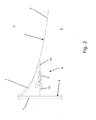
- Fig. 2 illustrates a section of an alternative embodiment, in which the hooks 11 are attached to the inner surface 3 of the tower wall 1 by welding.
- Fig. 3 illustrates a section of a further alternative embodiment, in which the fixation structure 11 comprises a flange.
- the flange 11 is attached to the inner surface 3 of the tower wall 1 by welding.
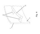
- Fig. 4 illustrates a fourth embodiment of how to distend a safety blanket 2 across the tower interior along an inner surface 3 of a wall 1 of a tower for a wind power installation.
- the blanket (not shown in the figure) is distended by use of a round iron bar 12 and a plurality of flat bars 13 welded to the inner surface.
- the blanket (not shown) is stretched in an outwards direction towards the inner surface 3 by a string (not shown) which can be elongated by elastic deformation.
- the string extends circumferentially about the central part (not shown), and crosses in and out between the round iron bar 12 and attachment points on the blanket.
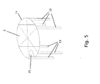
- Fig. 5 illustrates a fifth embodiment, in which the safety blanket 2 is distended across the tower interior along an inner surface (not shown) of a wall (not shown) of a tower for a wind power installation by use of a frame structure 14 having a plurality of legs 15.
- the blanket 2 is attached to the frame structure 14 which is positioned adjacent to the tower wall (not shown).
- the blanket 2 comprises an incision 16 along the rim forming passages between the blanket 2 and the wall.
- the incision is in this embodiment of a size so that it incises the central part 6.
- the incision 16 is positioned so that the safety blanket 2 can be distended even though a ladder (not shown) is mounted at the inner surface of the tower (not shown).
- the size of the incision is large enough to allow a person the climb the ladder while the blanket 2 is distended along the inner surface of the tower wall (not shown).
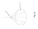
- Fig. 6 illustrates a sixth embodiment, in which the safety blanket 2 is mounted by use of a suspension structure 17.
- the suspension structure 17 may e.g. be attached to the main frame in the top of the tower or to a solid platform above the safety blanket. Other ways of attaching the safety blanket may also be used.
- Fig. 7 illustrates details of the rim 7 of an embodiment of a safety blanket 2 distended along the inner surface 3 of the tower wall 1.
- a string 9 extends circumferentially about the central part 6.
- the string 9 crosses in and out between attachment points on the blanket 2, i.e. the rings 10, and a number of hooks 11 fixed to the inner surface 3 of the tower wall 1.
- the hooks 11 are attached to the inner surface 3 of the tower wall 1 by welding.
- the illustrated rim 7 has a layered structure comprising layers of different materials, one of the layers being a foam material 18.
- the foam material 18 is surrounded by a sheet material of e.g. nylon, plastic, other synthetic materials, Kevlar, carbon fibres, tarpaulin, or other.
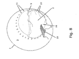
- Fig. 8 illustrates how a safety blanket 2 may be distended across the tower interior along the inner surface 3 of a wind turbine wall 1.
- the blanket 2 is not fully distended.
- a string 9 extends circumferentially about the central part 6 of the blanket 2. The string 9 crosses in and out between attachment points on the blanket 2, i.e. the rings 10 at the bottom of the blanket 2, and a number of hooks 11 fixed to the inner surface 3 of the tower wall 1.
- the blanket 2 comprises an incision 16 along the rim 7 forming passage between the blanket 2 and the wall 1.
- the incision 16 is in this embodiment of a size so that it incises the central part 6.
- the incision 16 is positioned so that the safety blanket 2 can be distended even though a ladder 19 is mounted at the inner surface 3 of the tower wall 1.
- Fig. 9 illustrates a section of a safety blanket 2 from below
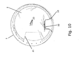
- Fig. 10 illustrates a safety blanket 2 from above.
- the string 9 extends circumferentially about the central part 6 of the blanket 2.
- the string 9 crosses in and out between the rings 10 and a number of hooks 11 fixed to the inner surface 3 of the tower wall 1.
- Fig. 10 three drainage openings 20 are shown. These drainage openings 20 can limit or even prevent built-up of water, oil, or other fluid media on the distended blanket 2, as the drainage openings allow draining of a fluid medium between the upper and lower compartments 4, 5. Furthermore, the drainage openings 20 can reduce pressure differences between the upper and lower compartments 4, 5.
- the blanket 2 comprises an incision 16 along the rim 7 forming a passage between the blanket 2 and the wall 1.
- the incision 16 is sized corresponding to the ladder 19 mounted at the inner surface 3 of the tower wall 1.
- Another incision 21 is sized corresponding to a lift (not shown) which in mounted in the tower. At the bottom of the tower the lift area and the ladder area are restricted areas so no nobody gets injured in case of fallen objects in these areas.
Landscapes
- Engineering & Computer Science (AREA)
- Architecture (AREA)
- Mechanical Engineering (AREA)
- Civil Engineering (AREA)
- Structural Engineering (AREA)
- Life Sciences & Earth Sciences (AREA)
- Sustainable Development (AREA)
- Sustainable Energy (AREA)
- Chemical & Material Sciences (AREA)
- Combustion & Propulsion (AREA)
- General Engineering & Computer Science (AREA)
- Wind Motors (AREA)
Claims (15)
- Turm für eine Windenergieanlage, wobei der Turm eine Wand (1) aufweist, die sich von einem Fundament in einer Aufwärtsrichtung bis zu einem Turmkopf hin erstreckt und die einen umschlossenen Raum festlegt, wobei der Turm ferner eine Schutzdecke (2) aufweist, die über das Turminnere hinweg entlang einer Innenfläche (3) der Wand gezogen ist, um dadurch den umschlossenen Raum in eine obere Kammer (4) über der Decke (2)und eine untere Kammer (5) unter der Decke (2) zu unterteilen, wobei die Schutzdecke (2) flexibel ist und wobei die Schutzdecke (2) einen Mittelteil (6) und einen Randbereich (7) umfasst, der sich entlang des Umfangs um den Mittelteil herum erstreckt, wobei die Biegesteifigkeit des Randbereichs (7) größer als die Biegesteifigkeit des Mittelteils (6) ist.
- Turm nach Anspruch 1, wobei die Biegesteifigkeit des Randbereichs (7) ausreicht, um zu gewährleisten, dass der Randbereich ein weitgehend selbsttragendes Element ist.
- Turm nach Anspruch 1 oder 2, wobei die Sicherheitsdecke (2) an einer starren Befestigungskonstruktion (11) angebracht ist, die an der Innenfläche (3) angebracht ist.
- Turm nach Anspruch 3, wobei die starre Befestigungskonstruktion (11) ablösbar angebracht ist.
- Turm nach einem der vorhergehenden Ansprüche, wobei die Schutzdecke (2) in einer Richtung nach außen zur Innenfläche (3) hin durch eine Befestigungskonstruktion (8) gespannt ist, die an der Schutzdecke (2) an Orten zwischen dem Mittelteil (6) und dem Randbereich (7) angreift.
- Turm nach Anspruch 5, wobei die Befestigungskonstruktion (8) ein Seil (9) aufweist, das durch elastische Verformung gespannt werden kann, wobei sich das Seil in einer Umfangsrichtung um den Mittelteil (6) herum erstreckt.
- Turm nach Anspruch 6, wobei sich der Randbereich (7) in Umfangsrichtung über mindestens einen Teil des Seiles (9) erstreckt.
- Turm nach Anspruch 6 oder 7, wobei das Seil (9) durch die starre Befestigungskonstruktion (11) auf der Innenfläche (3) gehalten wird.
- Turm nach einem der vorhergehenden Ansprüche, wobei der Randbereich (7) eine Schichtstruktur aufweist, die Schichten unterschiedlicher Materialien umfasst.
- Turm nach Anspruch 9, wobei eine der Schichten ein Schaumstoffmaterial (18) aufweist.
- Turm nach einem der vorhergehenden Ansprüche, wobei der Mittelteil (6) ein Faservliesbahnmaterial aufweist.
- Turm nach einem der vorhergehenden Ansprüche, wobei die Form der Decke (2) eine hohe Anfangsstabilität besitzt.
- Turm nach einem der vorhergehenden Ansprüche, wobei die Decke (2) einen oder mehrere Einschnitte (16) entlang des Randbereichs (7) aufweist, die Durchlässe zwischen der Decke (2) und der Wand bilden.
- Turm nach einem der vorhergehenden Ansprüche, wobei der Mittelteil (6) mindestens eine Abflussöffnung (20) aufweist, um den Abfluss eines flüssigen Mediums zwischen der oberen (4) und der unteren Kammer (5) zu ermöglichen.
- Verfahren zum Aufziehen einer Sicherheitsdecke (2) über den Innenraum des Turms hinweg entlang einer Innenfläche (3) einer Wand (1) eines Turms für eine Windenergieanlage, wobei das Verfahren die Schritte umfasst zum- Bereitstellen einer Decke (2), die flexibel ist, wobei die Sicherheitsdecke einen Mittelteil (6) und einen Randbereich (7) umfasst, der sich in Umfangsrichtung um den Mittelteil (6) herum erstreckt, und wobei die Biegesteifigkeit des Randbereichs (7) größer als die Biegesteifigkeit des Mittelteils (6) ist, und- Spannen der Decke (2) in einer Richtung nach außen zur Innenfläche (3) hin, wobei eine Befestigungskonstruktion (8, 9, 10, 11) verwendet wird, die an Orten auf der Decke (2) angreift.
Applications Claiming Priority (3)
| Application Number | Priority Date | Filing Date | Title |
|---|---|---|---|
| US25722109P | 2009-11-02 | 2009-11-02 | |
| DKPA200970185 | 2009-11-02 | ||
| PCT/EP2010/066614 WO2011051492A2 (en) | 2009-11-02 | 2010-11-02 | A safety blanket |
Publications (2)
| Publication Number | Publication Date |
|---|---|
| EP2496831A2 EP2496831A2 (de) | 2012-09-12 |
| EP2496831B1 true EP2496831B1 (de) | 2013-08-14 |
Family
ID=43922681
Family Applications (1)
| Application Number | Title | Priority Date | Filing Date |
|---|---|---|---|
| EP10773905.4A Not-in-force EP2496831B1 (de) | 2009-11-02 | 2010-11-02 | Schutzdecke für einen turm einer windenergieanlage |
Country Status (4)
| Country | Link |
|---|---|
| US (1) | US8707656B2 (de) |
| EP (1) | EP2496831B1 (de) |
| ES (1) | ES2427741T3 (de) |
| WO (1) | WO2011051492A2 (de) |
Families Citing this family (6)
| Publication number | Priority date | Publication date | Assignee | Title |
|---|---|---|---|---|
| US20150300323A1 (en) * | 2011-09-14 | 2015-10-22 | General Electric Company | System and method for collecting fluid leaking from a wind turbine component |
| DE102011088920A1 (de) * | 2011-12-16 | 2013-06-20 | Suzlon Energy Gmbh | Auffangvorrichtung für eine Flüssigkeit einer Triebstrangkomponente |
| US9487960B2 (en) | 2014-06-17 | 2016-11-08 | One Energy Enterprises Llc | Suspended deck systems, kits, and methods of installing, inspecting, and repairing a suspended deck system |
| DK3067553T3 (da) * | 2015-03-13 | 2019-10-14 | Ge Renewable Tech Wind Bv | Sikkerhedsstruktur til udførelse af vedligeholdelsesarbejde på en vindmølle og fremgangsmåde til installering deraf |
| CN108320823B (zh) * | 2018-03-20 | 2024-05-07 | 阳江核电有限公司 | 核电凝汽器内防落物平台 |
| WO2025256720A1 (en) * | 2024-06-10 | 2025-12-18 | General Electric Renovables España S.L. | Methods and systems for covering a wind turbine tower section |
Family Cites Families (28)
| Publication number | Priority date | Publication date | Assignee | Title |
|---|---|---|---|---|
| US896213A (en) * | 1907-05-28 | 1908-08-18 | John S Kerfoot | Safety-net for elevator-shafts. |
| US952871A (en) | 1909-04-05 | 1910-03-22 | Thomas F Browder | Life-saving machine. |
| US1847250A (en) * | 1931-03-05 | 1932-03-01 | Emma C Maynes | Amusement ride |
| US2128268A (en) * | 1931-05-14 | 1938-08-30 | Lisle F Small | Means for securing turbine blades |
| US2145232A (en) * | 1937-06-24 | 1939-01-31 | Missouri Rolling Mill Corp | Steel tower member |
| US3693729A (en) * | 1970-02-19 | 1972-09-26 | Global Marine Inc | Air cushion drilling vehicle |
| US3910452A (en) * | 1972-12-01 | 1975-10-07 | Sandborn Edmund | Floating cover for a storage tank |
| US4079264A (en) * | 1976-05-03 | 1978-03-14 | Nathan Cohen | Wind or water operated power plant |
| US4130216A (en) * | 1977-04-05 | 1978-12-19 | Altech Industries, Inc. | Peripheral seal for floating roofs |
| US4202460A (en) * | 1978-04-13 | 1980-05-13 | Imbeault Fernand A | Sectional floating cover |
| US4696135A (en) * | 1986-03-25 | 1987-09-29 | Custodis-Cottrell, Inc. | Method and apparatus for constructing towers |
| US5167299A (en) * | 1991-11-08 | 1992-12-01 | Arthur Nusbaum | Safety net arrangement for building elevator shafts |
| US5711336A (en) * | 1996-07-24 | 1998-01-27 | Nirmel; Chittaranjan N. | Sunbather's shelter against chill winds and wind-blown sand |
| US6325085B1 (en) * | 1997-05-21 | 2001-12-04 | Targus International Company | Flexible protective system to prevent penetration of wind borne missiles |
| US6247277B1 (en) * | 1998-04-30 | 2001-06-19 | Robert S. Kerpash, Sr. | Grain storage safety net system and method |
| US6922956B2 (en) * | 2001-06-11 | 2005-08-02 | Petrex, Inc. | Floating cover |
| DK200200178A (da) | 2002-02-06 | 2003-08-07 | Vestas Wind Sys As | Ophængningsmidler til vindturbinetårne |
| JP3881306B2 (ja) | 2002-12-18 | 2007-02-14 | 日本電信電話株式会社 | 墜落防止網の取付方法 |
| US7321291B2 (en) * | 2004-10-26 | 2008-01-22 | Current Technologies, Llc | Power line communications system and method of operating the same |
| WO2005057620A2 (en) * | 2003-12-04 | 2005-06-23 | Essig John Raymond Jr | Modular inflatable multifunction field-deployable apparatus and methods of manufacture |
| NZ548485A (en) * | 2003-12-30 | 2009-06-26 | Pp Energy Aps | Device for enabling access to a structure above ground level |
| US20060201744A1 (en) * | 2005-03-14 | 2006-09-14 | Susan Curtis | Elevator shaft safety net system |
| ES2283192B1 (es) * | 2005-09-16 | 2008-09-16 | GAMESA INNOVATION & TECHNOLOGY, S.L. | Metodo de montaje de elementos en el interior de la torre de un aerogenerador. |
| CN2849042Y (zh) * | 2005-11-08 | 2006-12-20 | 杭州善庆金属构件有限公司 | 安全型单管塔 |
| KR100969957B1 (ko) | 2007-12-28 | 2010-07-15 | 주식회사 효성 | 안전사고 방지 장치를 갖춘 풍력 발전기 |
| CN201165943Y (zh) * | 2008-02-01 | 2008-12-17 | 北京能高自动化技术有限公司 | 一种大型风机塔筒内的安全平台 |
| CN102265030B (zh) * | 2010-03-15 | 2014-12-17 | 三菱重工业株式会社 | 风力发电装置及使用于该装置的电缆支承结构 |
| US8038398B2 (en) * | 2010-10-06 | 2011-10-18 | General Electric Company | System and method of distributing air within a wind turbine |
-
2010
- 2010-11-02 US US13/504,657 patent/US8707656B2/en not_active Expired - Fee Related
- 2010-11-02 ES ES10773905T patent/ES2427741T3/es active Active
- 2010-11-02 WO PCT/EP2010/066614 patent/WO2011051492A2/en not_active Ceased
- 2010-11-02 EP EP10773905.4A patent/EP2496831B1/de not_active Not-in-force
Also Published As
| Publication number | Publication date |
|---|---|
| US20120210659A1 (en) | 2012-08-23 |
| WO2011051492A3 (en) | 2011-10-27 |
| US8707656B2 (en) | 2014-04-29 |
| WO2011051492A2 (en) | 2011-05-05 |
| ES2427741T3 (es) | 2013-10-31 |
| EP2496831A2 (de) | 2012-09-12 |
Similar Documents
| Publication | Publication Date | Title |
|---|---|---|
| US8707656B2 (en) | Safety blanket | |
| EP3438449B1 (de) | Selbsttragende unterstützungsstruktur für windturbine-geräte | |
| US11073138B2 (en) | Wind turbine nacelle platform structure | |
| US20120152651A1 (en) | Heli-hoist platform | |
| US20100232977A1 (en) | Height Adjustable Wind Turbine Nacelle | |
| CA2554663A1 (en) | Tower for a wind turbine, prefabricated metal wall part for use in a tower for a wind turbine and method for constructing a tower for a wind turbine | |
| EP2484893A2 (de) | Wartungsplattform für Rotor einer Windkraftanlage | |
| AU2003292712A1 (en) | Crosswind-resistant outdoor tent | |
| AU2009243464A1 (en) | Method and system for coupling a stair platform to a tower of a wind energy turbine | |
| US9869294B2 (en) | Safety structure for performing servicing operations in a wind turbine and method for its installation | |
| US20250137440A1 (en) | Method of servicing a wind turbine rotor blade | |
| CN102052258B (zh) | 安全膜 | |
| EP3239406A1 (de) | Stützstruktur für offshore-windturbine | |
| EP4136346B1 (de) | Anpassbare anordnung einer turmplattform | |
| CN218406741U (zh) | 一种安全型海上漂浮游泳池 | |
| KR102713504B1 (ko) | 끈과 애드벌룬을 이용하여 기능이 향상되고, 강한 바람에도 견딜 수 있는 그늘막 | |
| EP3690242A1 (de) | Windturbine und verfahren zur montage eines windturbinenturms | |
| KR101428329B1 (ko) | 풍력발전기 및 풍력발전기 설치장치 | |
| CN211447860U (zh) | 一种工具式外悬挑防护装置 | |
| KR20200079302A (ko) | 윈드 터빈 작업 플랫폼 | |
| EP2388411A1 (de) | Windturbinen-Turm | |
| CN223739299U (zh) | 海上光伏的桩基爬梯结构 | |
| AU2012101066A4 (en) | Guide system and method for erecting power transmission line towers | |
| DK202170410A1 (en) | Improvements relating to servicing of wind turbine blades | |
| CN113982865B (zh) | 一种底部附带环状操作台模块的机舱罩及其工作方法 |
Legal Events
| Date | Code | Title | Description |
|---|---|---|---|
| PUAI | Public reference made under article 153(3) epc to a published international application that has entered the european phase |
Free format text: ORIGINAL CODE: 0009012 |
|
| 17P | Request for examination filed |
Effective date: 20120531 |
|
| AK | Designated contracting states |
Kind code of ref document: A2 Designated state(s): AL AT BE BG CH CY CZ DE DK EE ES FI FR GB GR HR HU IE IS IT LI LT LU LV MC MK MT NL NO PL PT RO RS SE SI SK SM TR |
|
| DAX | Request for extension of the european patent (deleted) | ||
| GRAP | Despatch of communication of intention to grant a patent |
Free format text: ORIGINAL CODE: EPIDOSNIGR1 |
|
| INTG | Intention to grant announced |
Effective date: 20130521 |
|
| GRAS | Grant fee paid |
Free format text: ORIGINAL CODE: EPIDOSNIGR3 |
|
| GRAA | (expected) grant |
Free format text: ORIGINAL CODE: 0009210 |
|
| AK | Designated contracting states |
Kind code of ref document: B1 Designated state(s): AL AT BE BG CH CY CZ DE DK EE ES FI FR GB GR HR HU IE IS IT LI LT LU LV MC MK MT NL NO PL PT RO RS SE SI SK SM TR |
|
| REG | Reference to a national code |
Ref country code: GB Ref legal event code: FG4D |
|
| REG | Reference to a national code |
Ref country code: AT Ref legal event code: REF Ref document number: 627021 Country of ref document: AT Kind code of ref document: T Effective date: 20130815 Ref country code: CH Ref legal event code: EP |
|
| REG | Reference to a national code |
Ref country code: IE Ref legal event code: FG4D |
|
| REG | Reference to a national code |
Ref country code: DE Ref legal event code: R096 Ref document number: 602010009512 Country of ref document: DE Effective date: 20131017 |
|
| REG | Reference to a national code |
Ref country code: ES Ref legal event code: FG2A Ref document number: 2427741 Country of ref document: ES Kind code of ref document: T3 Effective date: 20131031 |
|
| REG | Reference to a national code |
Ref country code: AT Ref legal event code: MK05 Ref document number: 627021 Country of ref document: AT Kind code of ref document: T Effective date: 20130814 Ref country code: NL Ref legal event code: VDEP Effective date: 20130814 |
|
| REG | Reference to a national code |
Ref country code: LT Ref legal event code: MG4D |
|
| PG25 | Lapsed in a contracting state [announced via postgrant information from national office to epo] |
Ref country code: NO Free format text: LAPSE BECAUSE OF FAILURE TO SUBMIT A TRANSLATION OF THE DESCRIPTION OR TO PAY THE FEE WITHIN THE PRESCRIBED TIME-LIMIT Effective date: 20131114 Ref country code: SE Free format text: LAPSE BECAUSE OF FAILURE TO SUBMIT A TRANSLATION OF THE DESCRIPTION OR TO PAY THE FEE WITHIN THE PRESCRIBED TIME-LIMIT Effective date: 20130814 Ref country code: LT Free format text: LAPSE BECAUSE OF FAILURE TO SUBMIT A TRANSLATION OF THE DESCRIPTION OR TO PAY THE FEE WITHIN THE PRESCRIBED TIME-LIMIT Effective date: 20130814 Ref country code: IS Free format text: LAPSE BECAUSE OF FAILURE TO SUBMIT A TRANSLATION OF THE DESCRIPTION OR TO PAY THE FEE WITHIN THE PRESCRIBED TIME-LIMIT Effective date: 20131214 Ref country code: AT Free format text: LAPSE BECAUSE OF FAILURE TO SUBMIT A TRANSLATION OF THE DESCRIPTION OR TO PAY THE FEE WITHIN THE PRESCRIBED TIME-LIMIT Effective date: 20130814 Ref country code: CY Free format text: LAPSE BECAUSE OF FAILURE TO SUBMIT A TRANSLATION OF THE DESCRIPTION OR TO PAY THE FEE WITHIN THE PRESCRIBED TIME-LIMIT Effective date: 20130911 Ref country code: HR Free format text: LAPSE BECAUSE OF FAILURE TO SUBMIT A TRANSLATION OF THE DESCRIPTION OR TO PAY THE FEE WITHIN THE PRESCRIBED TIME-LIMIT Effective date: 20130814 Ref country code: PT Free format text: LAPSE BECAUSE OF FAILURE TO SUBMIT A TRANSLATION OF THE DESCRIPTION OR TO PAY THE FEE WITHIN THE PRESCRIBED TIME-LIMIT Effective date: 20131216 |
|
| PG25 | Lapsed in a contracting state [announced via postgrant information from national office to epo] |
Ref country code: FI Free format text: LAPSE BECAUSE OF FAILURE TO SUBMIT A TRANSLATION OF THE DESCRIPTION OR TO PAY THE FEE WITHIN THE PRESCRIBED TIME-LIMIT Effective date: 20130814 Ref country code: PL Free format text: LAPSE BECAUSE OF FAILURE TO SUBMIT A TRANSLATION OF THE DESCRIPTION OR TO PAY THE FEE WITHIN THE PRESCRIBED TIME-LIMIT Effective date: 20130814 Ref country code: GR Free format text: LAPSE BECAUSE OF FAILURE TO SUBMIT A TRANSLATION OF THE DESCRIPTION OR TO PAY THE FEE WITHIN THE PRESCRIBED TIME-LIMIT Effective date: 20131115 Ref country code: BE Free format text: LAPSE BECAUSE OF FAILURE TO SUBMIT A TRANSLATION OF THE DESCRIPTION OR TO PAY THE FEE WITHIN THE PRESCRIBED TIME-LIMIT Effective date: 20130814 Ref country code: SI Free format text: LAPSE BECAUSE OF FAILURE TO SUBMIT A TRANSLATION OF THE DESCRIPTION OR TO PAY THE FEE WITHIN THE PRESCRIBED TIME-LIMIT Effective date: 20130814 Ref country code: LV Free format text: LAPSE BECAUSE OF FAILURE TO SUBMIT A TRANSLATION OF THE DESCRIPTION OR TO PAY THE FEE WITHIN THE PRESCRIBED TIME-LIMIT Effective date: 20130814 |
|
| PG25 | Lapsed in a contracting state [announced via postgrant information from national office to epo] |
Ref country code: CY Free format text: LAPSE BECAUSE OF FAILURE TO SUBMIT A TRANSLATION OF THE DESCRIPTION OR TO PAY THE FEE WITHIN THE PRESCRIBED TIME-LIMIT Effective date: 20130814 |
|
| PG25 | Lapsed in a contracting state [announced via postgrant information from national office to epo] |
Ref country code: RO Free format text: LAPSE BECAUSE OF FAILURE TO SUBMIT A TRANSLATION OF THE DESCRIPTION OR TO PAY THE FEE WITHIN THE PRESCRIBED TIME-LIMIT Effective date: 20130814 Ref country code: CZ Free format text: LAPSE BECAUSE OF FAILURE TO SUBMIT A TRANSLATION OF THE DESCRIPTION OR TO PAY THE FEE WITHIN THE PRESCRIBED TIME-LIMIT Effective date: 20130814 Ref country code: SK Free format text: LAPSE BECAUSE OF FAILURE TO SUBMIT A TRANSLATION OF THE DESCRIPTION OR TO PAY THE FEE WITHIN THE PRESCRIBED TIME-LIMIT Effective date: 20130814 Ref country code: EE Free format text: LAPSE BECAUSE OF FAILURE TO SUBMIT A TRANSLATION OF THE DESCRIPTION OR TO PAY THE FEE WITHIN THE PRESCRIBED TIME-LIMIT Effective date: 20130814 Ref country code: NL Free format text: LAPSE BECAUSE OF FAILURE TO SUBMIT A TRANSLATION OF THE DESCRIPTION OR TO PAY THE FEE WITHIN THE PRESCRIBED TIME-LIMIT Effective date: 20130814 Ref country code: DK Free format text: LAPSE BECAUSE OF FAILURE TO SUBMIT A TRANSLATION OF THE DESCRIPTION OR TO PAY THE FEE WITHIN THE PRESCRIBED TIME-LIMIT Effective date: 20130814 |
|
| PG25 | Lapsed in a contracting state [announced via postgrant information from national office to epo] |
Ref country code: IT Free format text: LAPSE BECAUSE OF FAILURE TO SUBMIT A TRANSLATION OF THE DESCRIPTION OR TO PAY THE FEE WITHIN THE PRESCRIBED TIME-LIMIT Effective date: 20130814 |
|
| PLBE | No opposition filed within time limit |
Free format text: ORIGINAL CODE: 0009261 |
|
| STAA | Information on the status of an ep patent application or granted ep patent |
Free format text: STATUS: NO OPPOSITION FILED WITHIN TIME LIMIT |
|
| 26N | No opposition filed |
Effective date: 20140515 |
|
| PG25 | Lapsed in a contracting state [announced via postgrant information from national office to epo] |
Ref country code: MC Free format text: LAPSE BECAUSE OF FAILURE TO SUBMIT A TRANSLATION OF THE DESCRIPTION OR TO PAY THE FEE WITHIN THE PRESCRIBED TIME-LIMIT Effective date: 20130814 |
|
| REG | Reference to a national code |
Ref country code: IE Ref legal event code: MM4A |
|
| REG | Reference to a national code |
Ref country code: DE Ref legal event code: R097 Ref document number: 602010009512 Country of ref document: DE Effective date: 20140515 |
|
| PG25 | Lapsed in a contracting state [announced via postgrant information from national office to epo] |
Ref country code: IE Free format text: LAPSE BECAUSE OF NON-PAYMENT OF DUE FEES Effective date: 20131102 |
|
| PGFP | Annual fee paid to national office [announced via postgrant information from national office to epo] |
Ref country code: GB Payment date: 20141124 Year of fee payment: 5 |
|
| REG | Reference to a national code |
Ref country code: CH Ref legal event code: PCOW Free format text: NEW ADDRESS: HEDEAGER 42, 8200 AARHUS N (DK) |
|
| PG25 | Lapsed in a contracting state [announced via postgrant information from national office to epo] |
Ref country code: SM Free format text: LAPSE BECAUSE OF FAILURE TO SUBMIT A TRANSLATION OF THE DESCRIPTION OR TO PAY THE FEE WITHIN THE PRESCRIBED TIME-LIMIT Effective date: 20130814 |
|
| REG | Reference to a national code |
Ref country code: CH Ref legal event code: PL |
|
| PG25 | Lapsed in a contracting state [announced via postgrant information from national office to epo] |
Ref country code: BG Free format text: LAPSE BECAUSE OF FAILURE TO SUBMIT A TRANSLATION OF THE DESCRIPTION OR TO PAY THE FEE WITHIN THE PRESCRIBED TIME-LIMIT Effective date: 20130814 Ref country code: LU Free format text: LAPSE BECAUSE OF NON-PAYMENT OF DUE FEES Effective date: 20131102 Ref country code: RS Free format text: LAPSE BECAUSE OF FAILURE TO SUBMIT A TRANSLATION OF THE DESCRIPTION OR TO PAY THE FEE WITHIN THE PRESCRIBED TIME-LIMIT Effective date: 20131114 Ref country code: LI Free format text: LAPSE BECAUSE OF NON-PAYMENT OF DUE FEES Effective date: 20141130 Ref country code: CH Free format text: LAPSE BECAUSE OF NON-PAYMENT OF DUE FEES Effective date: 20141130 Ref country code: HU Free format text: LAPSE BECAUSE OF FAILURE TO SUBMIT A TRANSLATION OF THE DESCRIPTION OR TO PAY THE FEE WITHIN THE PRESCRIBED TIME-LIMIT; INVALID AB INITIO Effective date: 20101102 Ref country code: MK Free format text: LAPSE BECAUSE OF FAILURE TO SUBMIT A TRANSLATION OF THE DESCRIPTION OR TO PAY THE FEE WITHIN THE PRESCRIBED TIME-LIMIT Effective date: 20130814 |
|
| PG25 | Lapsed in a contracting state [announced via postgrant information from national office to epo] |
Ref country code: MT Free format text: LAPSE BECAUSE OF FAILURE TO SUBMIT A TRANSLATION OF THE DESCRIPTION OR TO PAY THE FEE WITHIN THE PRESCRIBED TIME-LIMIT Effective date: 20130814 |
|
| REG | Reference to a national code |
Ref country code: FR Ref legal event code: PLFP Year of fee payment: 6 |
|
| PGFP | Annual fee paid to national office [announced via postgrant information from national office to epo] |
Ref country code: DE Payment date: 20151117 Year of fee payment: 6 |
|
| PGFP | Annual fee paid to national office [announced via postgrant information from national office to epo] |
Ref country code: FR Payment date: 20151130 Year of fee payment: 6 Ref country code: ES Payment date: 20151123 Year of fee payment: 6 |
|
| REG | Reference to a national code |
Ref country code: FR Ref legal event code: CA Effective date: 20160602 |
|
| GBPC | Gb: european patent ceased through non-payment of renewal fee |
Effective date: 20151102 |
|
| PG25 | Lapsed in a contracting state [announced via postgrant information from national office to epo] |
Ref country code: TR Free format text: LAPSE BECAUSE OF FAILURE TO SUBMIT A TRANSLATION OF THE DESCRIPTION OR TO PAY THE FEE WITHIN THE PRESCRIBED TIME-LIMIT Effective date: 20130814 |
|
| PG25 | Lapsed in a contracting state [announced via postgrant information from national office to epo] |
Ref country code: GB Free format text: LAPSE BECAUSE OF NON-PAYMENT OF DUE FEES Effective date: 20151102 |
|
| REG | Reference to a national code |
Ref country code: DE Ref legal event code: R119 Ref document number: 602010009512 Country of ref document: DE |
|
| REG | Reference to a national code |
Ref country code: FR Ref legal event code: ST Effective date: 20170731 |
|
| PG25 | Lapsed in a contracting state [announced via postgrant information from national office to epo] |
Ref country code: FR Free format text: LAPSE BECAUSE OF NON-PAYMENT OF DUE FEES Effective date: 20161130 |
|
| PG25 | Lapsed in a contracting state [announced via postgrant information from national office to epo] |
Ref country code: DE Free format text: LAPSE BECAUSE OF NON-PAYMENT OF DUE FEES Effective date: 20170601 |
|
| PG25 | Lapsed in a contracting state [announced via postgrant information from national office to epo] |
Ref country code: ES Free format text: LAPSE BECAUSE OF NON-PAYMENT OF DUE FEES Effective date: 20161103 |
|
| REG | Reference to a national code |
Ref country code: ES Ref legal event code: FD2A Effective date: 20180626 |
|
| PG25 | Lapsed in a contracting state [announced via postgrant information from national office to epo] |
Ref country code: AL Free format text: LAPSE BECAUSE OF FAILURE TO SUBMIT A TRANSLATION OF THE DESCRIPTION OR TO PAY THE FEE WITHIN THE PRESCRIBED TIME-LIMIT Effective date: 20130814 |