EP2497410A1 - Appareil ophtalmologique et procédé de commande de celui-ci - Google Patents
Appareil ophtalmologique et procédé de commande de celui-ci Download PDFInfo
- Publication number
- EP2497410A1 EP2497410A1 EP12158660A EP12158660A EP2497410A1 EP 2497410 A1 EP2497410 A1 EP 2497410A1 EP 12158660 A EP12158660 A EP 12158660A EP 12158660 A EP12158660 A EP 12158660A EP 2497410 A1 EP2497410 A1 EP 2497410A1
- Authority
- EP
- European Patent Office
- Prior art keywords
- image
- eye
- inspected
- fundus
- movement
- Prior art date
- Legal status (The legal status is an assumption and is not a legal conclusion. Google has not performed a legal analysis and makes no representation as to the accuracy of the status listed.)
- Granted
Links
- 238000000034 method Methods 0.000 title claims description 56
- 239000000284 extract Substances 0.000 claims abstract description 10
- 210000004204 blood vessel Anatomy 0.000 claims description 9
- 238000012014 optical coherence tomography Methods 0.000 claims description 9
- 230000008602 contraction Effects 0.000 claims description 2
- 238000003384 imaging method Methods 0.000 abstract description 18
- 210000001508 eye Anatomy 0.000 description 87
- 238000012545 processing Methods 0.000 description 42
- 238000000605 extraction Methods 0.000 description 21
- 238000011156 evaluation Methods 0.000 description 16
- 230000004424 eye movement Effects 0.000 description 12
- 238000001514 detection method Methods 0.000 description 5
- 238000005286 illumination Methods 0.000 description 5
- 230000003287 optical effect Effects 0.000 description 4
- 210000003733 optic disk Anatomy 0.000 description 3
- 238000004364 calculation method Methods 0.000 description 2
- 238000003745 diagnosis Methods 0.000 description 2
- 230000002194 synthesizing effect Effects 0.000 description 2
- 206010044565 Tremor Diseases 0.000 description 1
- 210000005252 bulbus oculi Anatomy 0.000 description 1
- 238000007796 conventional method Methods 0.000 description 1
- 238000005314 correlation function Methods 0.000 description 1
- 201000010099 disease Diseases 0.000 description 1
- 208000037265 diseases, disorders, signs and symptoms Diseases 0.000 description 1
- 210000003128 head Anatomy 0.000 description 1
- 238000012986 modification Methods 0.000 description 1
- 230000004048 modification Effects 0.000 description 1
- 238000002577 ophthalmoscopy Methods 0.000 description 1
- 230000006641 stabilisation Effects 0.000 description 1
- 238000011105 stabilization Methods 0.000 description 1
Images



Classifications
-
- A—HUMAN NECESSITIES
- A61—MEDICAL OR VETERINARY SCIENCE; HYGIENE
- A61B—DIAGNOSIS; SURGERY; IDENTIFICATION
- A61B3/00—Apparatus for testing the eyes; Instruments for examining the eyes
- A61B3/10—Objective types, i.e. instruments for examining the eyes independent of the patients' perceptions or reactions
- A61B3/113—Objective types, i.e. instruments for examining the eyes independent of the patients' perceptions or reactions for determining or recording eye movement
-
- A—HUMAN NECESSITIES
- A61—MEDICAL OR VETERINARY SCIENCE; HYGIENE
- A61B—DIAGNOSIS; SURGERY; IDENTIFICATION
- A61B3/00—Apparatus for testing the eyes; Instruments for examining the eyes
- A61B3/0016—Operational features thereof
- A61B3/0041—Operational features thereof characterised by display arrangements
- A61B3/0058—Operational features thereof characterised by display arrangements for multiple images
-
- A—HUMAN NECESSITIES
- A61—MEDICAL OR VETERINARY SCIENCE; HYGIENE
- A61B—DIAGNOSIS; SURGERY; IDENTIFICATION
- A61B3/00—Apparatus for testing the eyes; Instruments for examining the eyes
- A61B3/10—Objective types, i.e. instruments for examining the eyes independent of the patients' perceptions or reactions
- A61B3/12—Objective types, i.e. instruments for examining the eyes independent of the patients' perceptions or reactions for looking at the eye fundus, e.g. ophthalmoscopes
Definitions
- the present invention relates to an ophthalmologic apparatus and a control method thereof, and more particularly to an ophthalmologic apparatus that evaluates a fundus image used for extracting a template image in the case where pattern matching of a fundus image is executed in detection of biological motion, and a control method thereof.
- ophthalmologic images typified by fundus images have been used in medical practice as medical images for early detection of diseases.
- the influence of eye movement during photographing has been recognized as a serious problem for long years.
- eye movement may reduce clarity of ophthalmologic images to prevent an increase in accuracy of diagnosis or treatment.
- Human eyes are repeating involuntary slight vibration even during fixation on one point. This is referred to as involuntary eye movement. Since a patient cannot consciously stop involuntary eye movement, the influence of involuntary eye movement needs to be eliminated on the side of a medical practice tool or an operator in diagnosis or treatment of eyes.
- a medical practice tool needs to have measures against eye movement. For example, as disclosed in a document " Daniel X. Hammer, R. Daniel Ferguson, John C. Magill, and Michael A. White, 'Image stabilization for scanning laser ophthalmoscopy', OPTICS EXPRESS 10(26), 1542-1549 (2002 )", a tracking technique of applying a light to optic disk in a circular motion, and detecting and correcting eye movement by variation of reflection.
- a method is also proposed of scanning fundus to pick up tomographic images of fundus in a vertical direction (an eye depth direction) in positions shifted with time, and detecting eye movement using three-dimensional images synthesized from the tomographic images in a tomographic imaging apparatus.
- a small area having a certain characteristic is extracted from an entire fundus image, and movement of the small area between a plurality of continuous fundus images can be detected to detect movement of the entire fundus.
- This method a smaller amount of calculation is required than that in detecting movement of the entire fundus, thereby efficiently detecting movement of the fundus.
- An image of a small area having a certain characteristic used at this time is referred to as a template image, and a technique of pattern matching is used to detect movement of the template image.
- the pattern matching is a technique of searching an area most similar to the template image from the entire image to be referred to.
- a selected template image does not match an area to be detected or matches an area that is not to be detected in some cases, thereby causing false detection.
- a template image has to be properly selected.
- it is important that a fundus image from which a template image is extracted is a proper image including no eye motion.
- a method is disclosed of selecting a plurality of small areas having a characteristic from a fundus image and executing matching on fundus images picked up thereafter to detect changes of the fundus images with time.
- determining whether a fundus image from which a small area is selected includes eye motion is not disclosed.
- Japanese Patent No. 04466968 a technique is disclosed of synthesizing a plurality of tomographic images of fundus picked up in positions laterally shifted with time to once configure a three-dimensional image, and acquiring a lateral two-dimensional image of the fundus from the three-dimensional image to detect movement of the fundus.
- a step is necessary of acquiring and synthesizing a plurality of tomographic images and further converting the images into a lateral image of the fundus, the movement cannot be detected at high speed during imaging.
- Japanese Patent No. 04466968 does not disclose a technique of extracting a template image to execute tracking.
- the present invention has an object to select a fundus image that is less affected by eye motion in extraction of a template image.
- the present invention has another object to shorten an imaging time by selecting a fundus image that is less affected by eye motion.
- the present invention provides an ophthalmologic apparatus configured as described below and a control method thereof.
- the present invention provides an ophthalmologic apparatus that detects movement of an eye to be inspected using a template image extracted from a fundus image of the eye to be inspected, including: an acquiring unit that scans the eye to be inspected with a measuring light to acquire a fundus image of the eye to be inspected; and a determination unit that determines whether the acquired fundus image is a fundus image affected by movement of the eye to be inspected, wherein the template image is an image extracted from a fundus image determined to be not affected by the determination unit.
- the present invention also provides a control method of an ophthalmologic apparatus of detecting movement of an eye to be inspected using a template image extracted from a fundus image of the eye to be inspected, including: acquiring a fundus image from the eye to be inspected; and determining whether the fundus image is affected by movement of the eye to be inspected, wherein the template image is an image extracted from a fundus image determined to be not affected in the determining.
- a fundus image can be selected that is less affected by eye motion in extraction of a template image.
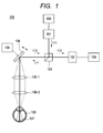
- FIG. 1 illustrates a configuration of an ophthalmologic imaging apparatus according to Embodiment 1 of the present invention.
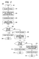
- FIG. 2 illustrates a flow for deciding a tracking template in Embodiment 1 of the present invention.
- FIGS. 3A, 3B and 3C illustrate evaluation of a fundus image in Embodiment 1 of the present invention.
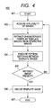
- FIG. 4 illustrates a flow for deciding a tracking template in Embodiment 2 of the present invention.
- FIGS. 5A, 5B and 5C illustrate evaluation of a fundus image in Embodiment 2 of the present invention.
- FIG. 6A, 6B, 6C and 6D illustrate evaluation of the fundus image in Embodiment 2 of the present invention.
- FIG. 7 illustrates a flow for deciding a tracking template in Embodiment 3 of the present invention.
- FIGS. 8A, 8B and 8C illustrate evaluation of a fundus image in Embodiment 3 of the present invention.
- FIG. 9 illustrates a template image for evaluating an image in Embodiment 3 of the present invention.
- FIG. 10 illustrates a searching point in Embodiment 1 of the present invention.
- FIGS. 11A, 11B, 11C and 11D illustrate evaluation of the fundus image in Embodiment 3 of the present invention.
- FIG. 12 illustrates a flow for deciding a tracking template in Embodiment 4 of the present invention.
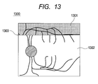
- FIG. 13 illustrates evaluation of a fundus image in Embodiment 4 of the present invention.
- a scanning laser ophthalmoscope to which the present invention is applied will be described.
- an apparatus will be herein described that extracts a template image from a picked-up first fundus image, and executes pattern matching on a further picked-up second fundus image to evaluate a fundus image, and decides a template image for movement detection of an eye to be inspected for tracking.
- the present invention is not limited to this, but includes a method of evaluating an image using one or more fundus images with respect to the extracted template image (also referred to as a characteristic image).
- FIG. 1 shows a plurality of memory-control-signal processing units 109 for convenience of drawing, but these memory-control-signal processing units 109 are actually the same component.
- An illumination light 111 as a measuring light emitted from a light source 101 is deflected by a half mirror 103, and scanned by an XY scanner 104.
- the XY scanner 104 corresponds to a scanning unit in the present invention. Between the XY scanner 104 and an eye to be inspected 108, lenses 106-1 and 106-2 for applying the illumination light 111 to fundus 107 are placed.
- the XY scanner 104 is shown as one mirror, but actually, two mirrors: an X scanning mirror and a Y scanning mirror are placed close to each other. Thus, the XY scanner 104 can execute raster scanning of the fundus 107 perpendicularly to an optical axis.
- the illumination light 111 entering the eye to be inspected 108 is reflected or scattered by the fundus 107, and returned as a return light 112.
- the return light 112 again enters the half mirror 103, and a light transmitted herein enters a sensor 102.
- the sensor 102 converts light intensity of the return light 112 at each measuring area on the fundus 107 into a voltage, and transmits a signal indicating the voltage to the memory-control-signal processing unit 109.
- the memory-control-signal processing unit 109 functions as an acquiring unit that generates a two-dimensional fundus image using the transmitted signal, scans the eye to be inspected with the measuring light, and acquires a fundus image of the eye to be inspected.
- the memory-control-signal processing unit 109 extracts a characteristic area including a crossing/branching region of blood vessels from the fundus image as a template image. Pattern matching on a newly generated fundus image is executed with the extracted template image to detect movement of the eye to be inspected (calculation of an amount of movement). Further, the memory-control-signal processing unit 109 controls a scanning angle of the XY scanner 104 depending on the calculated amount of movement to execute tracking.
- the memory-control-signal processing unit 109 includes a keyboard or a mouse (not shown) for external input.
- the memory-control-signal processing unit 109 controls start and finish of fundus imaging.
- the memory-control-signal processing unit 109 includes a monitor (not shown), and can display a fundus image or specific information (left or right eye, personal data of a subject) specifying the eye to be inspected.
- the template image extracted by the memory-control-signal processing unit 109 is stored in the memory-control-signal processing unit 109 together with input specific information.
- FIG. 2 shows a flow for deciding a movement detecting template image for executing tracking using the fundus imaging apparatus of this embodiment.
- FIGS. 3A to 3C show extraction of a template image from a picked-up fundus image and pattern matching.
- the light source 101 emits an illumination light 111.
- the memory-control-signal processing unit 109 starts scanning by the XY scanner 104 simultaneously with the command to start picking up a fundus image.
- the illumination light 111 is scanned by the XY scanner 104, passes through the lenses 106-1 and 106-2 and then enters the eye to be inspected 108 to execute raster scanning of the fundus 107 perpendicularly to an optical axis.
- the return light 112 reflected or scattered by the fundus 107 travels through the optical path in a reverse direction, passes through the half mirror 103 and enters the sensor 102.
- a signal converted into a voltage by the sensor 102 is transmitted to the memory-control-signal processing unit 109 to generate a first fundus image 301 (Step 202).
- a fundus image of 2000 pixels x 2000 pixels in size is acquired.
- the memory-control-signal processing unit 109 extracts a template image for image evaluation from the generated first fundus image (Step 203).
- a characteristic point such as branching/crossing of blood vessels in a fundus image may be extracted, and not limited to this.
- Optic disk or the like may be used as a characteristic point.
- the extracted template image is stored in the memory-control-signal processing unit 109.
- a coordinate that specifies a position of the extracted template image on the first fundus image is simultaneously stored.
- At least one template image may be extracted, but a plurality of template images are desirably extracted for more accurate image evaluation. Further, extracting areas of template images are desirably relatively separated from each other.
- the first fundus image is divided into four areas around the center as an origin, and one template image is extracted from each area.
- Four template images 302, 303, 304 and 305 are acquired from the first fundus image.
- the size of the template image is not limited, but may be larger than a crossing/branching region of blood vessels.
- the template image is 140 pixels x 140 pixels in size.
- a generally implemented technique may be used, and detailed descriptions thereof will be omitted.
- the memory-control-signal processing unit 109 transmits a signal to start picking up a fundus image to the light source 101, the sensor 102, and the XY scanner 104 to pick up a second fundus image 311 (Step 204).
- the searching point may be the entire second fundus image 311, but is desirably limited for image evaluation at higher speed.
- a point limited around the coordinate of the template image stored in the memory-control-signal processing unit 109 when the template image is acquired may be set as a searching point.
- points of 280 pixels x 280 pixels around the coordinates at which the template images are extracted are set as searching points 316, 317, 318 and 319, and compared and matched with the template images.
- FIG. 10 shows a relationship between the template image and the searching point in this embodiment using reference numerals in FIGS. 3A to 3C .
- a generally implemented pattern matching technique can be used, and detailed descriptions thereof will be omitted.
- the memory-control-signal processing unit 109 executes matching, determines how much the searching point is similar to the template image, and displays the result as similarity.
- a correlation function can be used. Whether matching is completed is determined by separating the similarity at a certain threshold.
- a threshold may be arbitrarily set by an operator. Thus, determination is executed for four template images such that when the similarity is less than the threshold, it is determined that matching is not completed, and when the similarity is the threshold or more, it is determined that matching is completed. Further, it is determined whether matching is completed for all of the four template images (Step 206).
- the memory-control-signal processing unit 109 functions as a determination unit that determines whether the acquired fundus image is affected by movement of the eye to be inspected.
- the memory-control-signal processing unit 109 functions as a selecting unit that selects, among a plurality of acquired images, an image that is less affected by movement of the eye to be inspected, or an image that is affected at a threshold or less at which predetermined similarity is acquired.
- a tracking template image is decided (Step 207).
- a characteristic point may be again extracted as a movement detecting template image for tracking, but a template image that has been extracted may be used.
- the eye motion (movement of the eye to be inspected) will be briefly described. The eye motion occurs from involuntary eye movement including tremor, flick, and drift, or movement of head. The result of the eye motion appears as one of discontinuity, expansion and contraction, and rotation of a fundus image, as an influence of movement of the eye to be inspected on the fundus image.
- being less (or not) affected by eye motion refers to that determination cannot be executed on the picked-up fundus image, that is, movement greater than resolution of the fundus image has not occurred during picking up of the fundus image.
- this is apparently not limited as described below.
- a determination criterion may be arbitrarily set by the operator depending on conditions of the eye to be inspected or the patient.
- the memory-control-signal processing unit 109 again acquires a fundus image as a third fundus image 321 (Step 209) .
- a movement detecting template image for tracking is decided (Step 212). Also, a characteristic point may be again extracted as a movement detecting template image for tracking, but a template image that has been extracted may be used.
- the template images 302 and 303 do not match searching points 326 and 327 on the third fundus image 321 ( FIG. 3C ).
- This result shows that the first fundus image 301 from which the template images are extracted is affected by eye motion.
- the memory-control-signal processing unit 109 determines that the first fundus image 301 is not suitable for extraction of a movement detecting template image for tracking.
- a movement detecting template image for tracking is extracted from the second fundus image 311 (Step 214).
- a third fundus image may be used for extracting a movement detecting template image for tracking.
- the memory-control-signal processing unit 109 functions as an extracting unit that extracts at least one characteristic point as a template image used for correcting the influence of movement of the eye to be inspected from a fundus image determined to be not affected by the movement of the eye to be inspected.
- the template image extracted by the memory-control-signal processing unit 109 in Step 214 is decided as a tracking template image (Step 215).
- the memory-control-signal processing unit 109 determines whether the template image extracted from the second fundus image 311 matches images in searching points 326 to 329 on the third fundus image 321. When the images match, a movement detecting template image for tracking is decided from the second fundus image 311. On the other hand, when the images do not match, as in Step 209, a new fourth image is acquired and matching is executed between the second image and the fourth image as in Step 210. When matching is not completed, as in Step 214, a template image is extracted from the third image. As such, a new image may be acquired to decide a template image until matching is completed.
- the template image is extracted from the first image (Step 203), then the second image is acquired (Step 204), and a third image is acquired depending on the result of determination of matching (Step 206) (Step 209), but the second and third images may be previously acquired in Step 202 to execute the process.
- the fourth image may be also previously acquired.
- the fundus image is evaluated as described above, and thus a fundus image that is not affected by eye motion can be selected to extract a movement detecting template image for tracking.
- the memory-control-signal processing unit 109 determines that the fundus image is not affected by the movement of the eye to be inspected to extract and select a movement detecting template image for tracking.
- the memory-control-signal processing unit 109 functions as a detecting unit that detects movement of the eye to be inspected using the selected image.
- the memory-control-signal processing unit 109 functions as a correcting unit that corrects the influence of the movement of the eye to be inspected with reference to the template image to execute tracking.
- a reference coordinate may be set on the basis of the fundus image from which the template image is extracted or of a newly picked-up fundus image. This can reduce burdens on the operator and the patient during fundus imaging to execute tracking with high accuracy.
- the SLO has been described, but the same advantage can be obtained if this method is applied to a fundus image acquiring apparatus, in particular, an optical coherence tomography (OCT) or the like.
- OCT optical coherence tomography
- This method may be applied to a fundus camera including a two-dimensional CCD as an imaging unit.
- the fundus image is described, but not limited to this.
- the embodiment may be applied to an anterior eye image.
- Embodiments described below may be also applied to an anterior eye image.
- an ophthalmologic apparatus that reduces errors in extraction of a template image to increase matching accuracy in fundus imaging, reduce burdens on the operator and the patient, and can select a fundus image that is less affected by eye motion, and a control method thereof may be provided.
- a scanning laser ophthalmoscope (SLO) to which the present invention is applied will be described.
- an apparatus will be herein described that extracts template images from a plurality of picked-up fundus images, executes matching between the template images to evaluate the fundus images, and decides a movement detecting template image for tracking.
- FIGS. 1 , 4 and 5 a method for evaluating fundus images using three fundus images will be particularly described in this embodiment.
- This embodiment has the same configuration as Embodiment 1, and thus descriptions on the configuration will be omitted.
- the ophthalmologic imaging apparatus 100 acquires a plurality of fundus images (Step 402).
- three fundus images a first fundus image 501, a second fundus image 511, and a third fundus image 521 are acquired.
- the operator may arbitrarily set the number of picked-up fundus images to two or more.
- template images 502, 503, 504, 505, 512, 513, 514, 515, 522, 523, 524 and 525 are extracted from the fundus images (Step 403).
- the memory-control-signal processing unit 109 executes matching using the template images extracted from the same area of the fundus images (Step 404).
- Matching is also executed in the second, third, and fourth areas.
- Matching is executed by the memory-control-signal processing unit 109 to determine how much the template images extracted from the same area are similar, and the result is displayed as similarity. Whether matching is completed is determined by separating the similarity at a certain threshold. A threshold may be arbitrarily set by the operator. Thus, when the similarity is less than the threshold, it is determined that matching is not completed, and when the similarity is the threshold or more, it is determined that matching is completed. Whether the fundus image is affected by eye motion is determined by how much the templates match in each area (Step 405). In this embodiment, it is determined that images with templates in all areas matching are substantially the same image.
- a determination criterion of images may be arbitrarily set by the operator depending on conditions of the eye to be inspected and the patient.
- the template 523 on the third fundus image 521 does not match the template 503 on the first fundus image 501 and the template 513 on the second fundus image 511, and the other templates match.
- the first fundus image 501 and the second fundus image 511 are substantially the same fundus image that is not affected by eye motion.
- the third fundus image 521 is a fundus image affected by eye motion.
- the process may return to (acquiring of fundus image) (Step 402), and a plurality of images may be again acquired.
- a characteristic point is extracted from the fundus image as a movement detecting template image for tracking.
- a template image extracted for evaluation of the fundus image can be used for movement detection for tracking, there is no need to extract a new template image, and a template image that has been extracted may be used as a movement detecting template image for tracking.
- the fundus image is evaluated as described above, and thus the fundus image that is not affected by eye motion can be selected to extract a movement detecting template image for tracking. This can reduce burdens on the operator and the patient during fundus imaging, thereby executing tracking with high accuracy.
- the SLO has been described, but the same advantage can be obtained if this method is applied to a fundus image acquiring apparatus, in particular, an OCT apparatus or the like.
- This method may be applied to a fundus camera including a two-dimensional CCD as an imaging unit.
- an apparatus will be described that acquires areas around a coordinate arbitrarily decided by an operator as template images from a first fundus image, rather than extracts a characteristic point as a template image, and executes matching on a plurality of fundus images for evaluation.
- an apparatus will be particularly described that executes pattern matching on second and third fundus images using a template image selected from a first fundus image.
- Embodiment 1 has the same configuration as Embodiment 1, and thus descriptions on the configuration will be omitted. Descriptions on parts overlapping Embodiments 1 and 2 will be omitted.
- a first fundus image 801 from which a template image is acquired is acquired (Step 702).
- a fundus image of 2000 pixels x 2000 pixels in size is acquired.
- the memory-control-signal processing unit 109 extracts a template image for image evaluation (Step 703).
- An extracting area of the template image may be arbitrarily selected from a first fundus image, but an area expected to include much branching or crossing of blood vessels is desirably previously set as a characteristic point in the fundus image.
- At least one template image may be extracted, but a plurality of template images are desirably extracted for more accurate image evaluation. Further, extracting areas of template images are desirably relatively separated from each other.
- the first fundus image is divided into four areas around the center as an origin, and one template image is extracted from each area.
- Four template images 802, 803, 804 and 805 ( FIG. 8A ) are acquired from the first fundus image.
- the template images are acquired around the center of the fundus image as the origin from the coordinates shown in FIG. 9 .
- the template image is 140 pixels x 140 pixels in size.
- the memory-control-signal processing unit 109 again acquires a fundus image for pattern matching (Step 704).
- a fundus image for pattern matching At this time, at least one image may be acquired, but a plurality of images may be acquired to increase accuracy of image evaluation.
- the number of acquired fundus images is not limited, but may be arbitrarily decided by the operator.
- a second fundus image 811 and a third fundus image 821 are newly acquired.
- the fundus image is acquired after extraction of the template image, but a plurality of fundus images may be acquired in acquiring of the first fundus image (Step 702) and a part of the fundus images may be used.
- the memory-control-signal processing unit 109 executes pattern matching using the template image 802, 803, 804 and 805 extracted from the first fundus image 801 (Step 705) ( FIG. 8B ). Pattern matching is executed on the plurality of fundus images acquired in Step 704, and in this embodiment, executed on the second fundus image 811 and the third fundus image 821. Searching points in matching may be the whole of the second fundus image 811 and the third fundus image 821, but are desirably limited for image evaluation at higher speed. In this case, points limited around the coordinate of the template image stored in the memory-control-signal processing unit 109 in acquiring of the template image may be set as searching points.
- points of 280 pixels x 280 pixels around the coordinate at which each template image shown in FIG. 9 is extracted are set as searching points 816, 817, 818, 819, 826, 827, 828 and 829 for matching.
- the memory-control-signal processing unit 109 determines whether matching is completed (Step 706).
- the memory-control-signal processing unit 109 executes matching, determines how much the template images extracted from the same area are similar, and displays the result as similarity. Whether the fundus image is affected by eye motion is determined by how much the templates match in each area. In this embodiment, it is determined that images with templates in all areas matching are substantially the same image. However, not limited to the setting of this embodiment, a determination criterion may be arbitrarily set by the operator depending on conditions of the eye to be inspected or the patient. The result of matching is shown in FIGS. 11A to 11D .
- the process may return to Step 702 to restart the steps.
- a characteristic point is extracted as a tracking template image from the fundus image.
- a characteristic point is extracted from the first fundus image 801.
- the characteristic point is extracted from the first fundus image 801, but may be extracted from the third fundus image 821.
- a characteristic point may be extracted from an arbitrary fundus image selected from the matched fundus images.
- the fundus image is evaluated as described above, and thus a fundus image that is not affected by eye motion can be selected to extract a movement detecting template image for tracking. This can reduce burdens on the operator and the patient during fundus imaging to execute tracking with high accuracy.
- the SLO has been described, but the same advantage can be obtained if this method is applied to a fundus image acquiring apparatus, in particular, an OCT apparatus or the like.
- This method may be applied to a fundus camera including a two-dimensional CCD as an imaging unit.
- an apparatus will be described that acquires one fundus image, determines whether the fundus image is affected by eye motion, and decides a movement detecting template image for tracking.
- an apparatus will be particularly described that detects discontinuity in a fundus image to determine presence/absence of eye motion, and decides a movement detecting template image for tracking.
- One fundus image 1300 used for evaluation is acquired (Step 1202).
- a memory-control-signal processing unit 109 determines continuity of an image from the acquired fundus image 1300.
- the continuity of an image is determined by detecting whether characteristic areas in images for determination of continuity are continuous (Step 1203).
- relatively large eye motion occurs during picking up of the fundus image 1300, and a fundus image portion 1302 is shifted from a fundus image portion 1301 with a discontinuous portion 1303 therebetween.
- a blood vessel, yellow spot, and optic disk are considered to be characteristic areas, but not limited to them.
- a blood vessel is set as a characteristic area to determine continuity.
- the method using the normalizing cross-correlation is used as an example for the method of determining the continuity using the characteristic area.
- the brightness value for respective pixel among acquired fundus image 1300 is calculated at the first and a profile of brightness value for one line is acquired.
- acquired brightness value profile is compared with a profile of neighboring line, and the similarity thereof is calculated.
- the similarity is presented as a value within 0 to 1, and the value of 1 means a perfectly matching state.
- the threshold value of the similarity is set 0.6, such value can be arbitrarily set by an operator.
- a case wherein the similarity between the lines neighboring therewith is low means that the continuity therebetween is not ensured, and it is recognized that discontinuous portion caused by such as an eyeball movement exists in the fundus image.
- the method using the normalizing cross-correlation is specified above, but the present invention is not limited to this. Any of methods for determining the continuity can be preferably used.
- Step 1204 When the memory-control-signal processing unit 109 determines that there is a discontinuous portion in one fundus image as in the fundus image 1300 (Step 1204), the process returns to Step 1202 to start acquiring of a fundus image. The memory-control-signal processing unit 109 repeats this until no discontinuous portion is detected in the acquired fundus image.
- the memory-control-signal processing unit 109 extracts a movement detecting template image for tracking. Extraction of a template image is the same as in Embodiment 1 (Extraction of template image 1), and thus descriptions thereof will be herein omitted.
- the fundus image is evaluated as described above, and thus a fundus image that is not affected by eye motion can be selected to extract a movement detecting template image for tracking. This can reduce burdens on the operator and the patient during fundus imaging to execute tracking with high accuracy.
- a template image is extracted when it is determined that there is no discontinuous portion in the fundus image, but not limited to this.
- the process may move to Step 1205, and when a discontinuous portion is a predetermined value or more, the process may move to Step 1202. Whether the discontinuous portion is a predetermined value or more is determined, for example, by determining whether the number of discontinuous portions in an image is a predetermined value or more.
- Embodiments 1 to 4 above may be arbitrarily combined. As an example of combination, Embodiments 1 and 4 may be combined.
- the process described in Embodiment 4 may be executed on the second image to decide a template image.
- the process described in Embodiment 4 may be executed on the second image and the third image, and a template image may be decided from an image with fewer discontinuous portions.
- Embodiments 1 to 4 are thus arbitrarily combined, thereby acquiring a more proper template image.
- the present invention is also realized by executing the process below. Specifically, software (program) for realizing the function of the embodiments described above is supplied to a system or an apparatus via a network or various storage media, and a computer (or a CPU or an MPU) in the system or the apparatus reads and executes the program.
- program for realizing the function of the embodiments described above is supplied to a system or an apparatus via a network or various storage media, and a computer (or a CPU or an MPU) in the system or the apparatus reads and executes the program.
Landscapes
- Health & Medical Sciences (AREA)
- Life Sciences & Earth Sciences (AREA)
- Engineering & Computer Science (AREA)
- Medical Informatics (AREA)
- Surgery (AREA)
- Biophysics (AREA)
- Biomedical Technology (AREA)
- Heart & Thoracic Surgery (AREA)
- Physics & Mathematics (AREA)
- Molecular Biology (AREA)
- Ophthalmology & Optometry (AREA)
- Animal Behavior & Ethology (AREA)
- General Health & Medical Sciences (AREA)
- Public Health (AREA)
- Veterinary Medicine (AREA)
- Human Computer Interaction (AREA)
- Eye Examination Apparatus (AREA)
- Image Analysis (AREA)
Applications Claiming Priority (1)
| Application Number | Priority Date | Filing Date | Title |
|---|---|---|---|
| JP2011052296 | 2011-03-10 |
Publications (2)
| Publication Number | Publication Date |
|---|---|
| EP2497410A1 true EP2497410A1 (fr) | 2012-09-12 |
| EP2497410B1 EP2497410B1 (fr) | 2019-05-29 |
Family
ID=45894114
Family Applications (1)
| Application Number | Title | Priority Date | Filing Date |
|---|---|---|---|
| EP12158660.6A Active EP2497410B1 (fr) | 2011-03-10 | 2012-03-08 | Appareil ophtalmologique et procédé de commande de celui-ci |
Country Status (5)
| Country | Link |
|---|---|
| US (1) | US9161690B2 (fr) |
| EP (1) | EP2497410B1 (fr) |
| JP (1) | JP5301001B2 (fr) |
| KR (1) | KR101483501B1 (fr) |
| CN (1) | CN102670168B (fr) |
Cited By (1)
| Publication number | Priority date | Publication date | Assignee | Title |
|---|---|---|---|---|
| US11508062B2 (en) * | 2019-03-29 | 2022-11-22 | Nidek Co., Ltd. | Ophthalmological image processing apparatus |
Families Citing this family (39)
| Publication number | Priority date | Publication date | Assignee | Title |
|---|---|---|---|---|
| CN103096785B (zh) | 2010-03-12 | 2015-09-30 | 佳能株式会社 | 眼科设备及其控制方法 |
| JP5818409B2 (ja) | 2010-06-17 | 2015-11-18 | キヤノン株式会社 | 眼底撮像装置及びその制御方法 |
| JP5794664B2 (ja) * | 2011-01-20 | 2015-10-14 | キヤノン株式会社 | 断層画像生成装置及び断層画像生成方法 |
| JP5917004B2 (ja) | 2011-03-10 | 2016-05-11 | キヤノン株式会社 | 撮像装置及び撮像装置の制御方法 |
| JP5913999B2 (ja) | 2012-01-16 | 2016-05-11 | キヤノン株式会社 | 眼科撮像装置およびその制御方法 |
| JP5997457B2 (ja) | 2012-02-21 | 2016-09-28 | キヤノン株式会社 | 撮像装置及び撮像装置の制御方法 |
| JP5955020B2 (ja) | 2012-02-21 | 2016-07-20 | キヤノン株式会社 | 眼底撮像装置及び方法 |
| JP6025349B2 (ja) | 2012-03-08 | 2016-11-16 | キヤノン株式会社 | 画像処理装置、光干渉断層撮像装置、画像処理方法および光干渉断層撮像方法 |
| JP6224908B2 (ja) | 2013-04-17 | 2017-11-01 | キヤノン株式会社 | 撮像装置 |
| EP2865323B1 (fr) * | 2013-10-23 | 2022-02-16 | Canon Kabushiki Kaisha | Suivi de mouvements de la rétine dans une tomographie par cohérence optique |
| JP6482171B2 (ja) | 2014-01-10 | 2019-03-13 | キヤノン株式会社 | 偏光oct装置 |
| US9211064B2 (en) | 2014-02-11 | 2015-12-15 | Welch Allyn, Inc. | Fundus imaging system |
| US9237847B2 (en) | 2014-02-11 | 2016-01-19 | Welch Allyn, Inc. | Ophthalmoscope device |
| KR101661159B1 (ko) * | 2014-04-08 | 2016-09-29 | 서울대학교산학협력단 | 레이저 시술 평가 시스템 및 평가 방법 |
| JP6322042B2 (ja) | 2014-04-28 | 2018-05-09 | キヤノン株式会社 | 眼科撮影装置、その制御方法、およびプログラム |
| JP6463048B2 (ja) | 2014-09-05 | 2019-01-30 | キヤノン株式会社 | 画像処理装置及び画像処理装置の作動方法 |
| JP6468764B2 (ja) | 2014-09-08 | 2019-02-13 | キヤノン株式会社 | 眼科装置 |
| JP6552200B2 (ja) | 2015-01-09 | 2019-07-31 | キヤノン株式会社 | 光断層撮像装置、その制御方法、及びプログラム |
| US11045088B2 (en) | 2015-02-27 | 2021-06-29 | Welch Allyn, Inc. | Through focus retinal image capturing |
| US10799115B2 (en) | 2015-02-27 | 2020-10-13 | Welch Allyn, Inc. | Through focus retinal image capturing |
| US10136804B2 (en) | 2015-07-24 | 2018-11-27 | Welch Allyn, Inc. | Automatic fundus image capture system |
| US10772495B2 (en) | 2015-11-02 | 2020-09-15 | Welch Allyn, Inc. | Retinal image capturing |
| US10413179B2 (en) | 2016-01-07 | 2019-09-17 | Welch Allyn, Inc. | Infrared fundus imaging system |
| CN105996978A (zh) * | 2016-05-04 | 2016-10-12 | 深圳市斯尔顿科技有限公司 | 一种多彩线扫描眼底成像设备 |
| US10602926B2 (en) | 2016-09-29 | 2020-03-31 | Welch Allyn, Inc. | Through focus retinal image capturing |
| CA3048197A1 (fr) | 2016-12-21 | 2018-06-28 | Acucela Inc. | Systeme de tomographie par coherence optique a faible cout, mobile et miniaturise pour applications ophtalmiques a domicile |
| US11096574B2 (en) | 2018-05-24 | 2021-08-24 | Welch Allyn, Inc. | Retinal image capturing |
| CN118576146A (zh) | 2018-06-20 | 2024-09-03 | 奥克塞拉有限公司 | 基于家庭的眼科应用的微型移动低成本光学相干断层扫描系统 |
| CN113164041A (zh) * | 2018-11-21 | 2021-07-23 | 华盛顿大学 | 用于远程眼科中的视网膜模板匹配的系统和方法 |
| JP7199236B2 (ja) * | 2019-01-24 | 2023-01-05 | 株式会社トプコン | 眼科装置 |
| JP7318272B2 (ja) * | 2019-03-29 | 2023-08-01 | 株式会社ニデック | 眼科撮影装置、および、眼科用画像処理プログラム |
| JP7318273B2 (ja) * | 2019-03-29 | 2023-08-01 | 株式会社ニデック | 眼科撮影装置、および、眼科用画像処理プログラム |
| US11730363B2 (en) | 2019-12-26 | 2023-08-22 | Acucela Inc. | Optical coherence tomography patient alignment system for home based ophthalmic applications |
| WO2021219773A1 (fr) * | 2020-04-29 | 2021-11-04 | Carl Zeiss Meditec, Inc. | Suivi d'image ir de fond d'œil en temps réel en présence d'artéfacts utilisant un point de repère de référence |
| US10959613B1 (en) | 2020-08-04 | 2021-03-30 | Acucela Inc. | Scan pattern and signal processing for optical coherence tomography |
| WO2022035809A1 (fr) | 2020-08-14 | 2022-02-17 | Acucela Inc. | Système et procédé d'alignement par courbure décroissante de balayage a de tomographie par cohérence optique |
| US11393094B2 (en) | 2020-09-11 | 2022-07-19 | Acucela Inc. | Artificial intelligence for evaluation of optical coherence tomography images |
| JP2023544704A (ja) | 2020-09-30 | 2023-10-25 | アキュセラ インコーポレイテッド | 近視の予測、診断、計画、および監視デバイス |
| WO2022204622A1 (fr) | 2021-03-24 | 2022-09-29 | Acucela Inc. | Dispositif de surveillance de mesure de longueur axiale |
Citations (6)
| Publication number | Priority date | Publication date | Assignee | Title |
|---|---|---|---|---|
| JPH10234674A (ja) | 1997-02-28 | 1998-09-08 | Nippon Telegr & Teleph Corp <Ntt> | 眼底画像の経時変化有無判定法 |
| WO2003053228A2 (fr) * | 2001-12-21 | 2003-07-03 | Sensomotoric Instruments Gmbh | Procede et appareil d'enregistrement de la position de l'oeil |
| US20060119794A1 (en) * | 2004-12-03 | 2006-06-08 | Hillis W D | Vision modification with reflected image |
| US20060239670A1 (en) * | 2005-04-04 | 2006-10-26 | Dixon Cleveland | Explicit raytracing for gimbal-based gazepoint trackers |
| US20100110275A1 (en) * | 2007-04-06 | 2010-05-06 | Gilles Mathieu | Large depth-of-field imaging system and iris recogniton system |
| WO2010052929A1 (fr) * | 2008-11-10 | 2010-05-14 | Canon Kabushiki Kaisha | Appareil, procede et programme de traitement d'images et support d'enregistrement de programme |
Family Cites Families (26)
| Publication number | Priority date | Publication date | Assignee | Title |
|---|---|---|---|---|
| JP3809661B2 (ja) * | 1995-12-28 | 2006-08-16 | ソニー株式会社 | 動き検出装置および動き検出方法 |
| IL132123A0 (en) * | 1997-04-01 | 2001-03-19 | Univ Johns Hopkins | A system for imaging an ocular fundus semi-automatically at high resolution and wide field |
| IL124814A (en) * | 1998-06-08 | 2003-04-10 | Grinvald Amiram | System and method for imaging and analysis of the movement of individual red blood corpuscles |
| JP4533013B2 (ja) | 2004-06-14 | 2010-08-25 | キヤノン株式会社 | 眼科装置 |
| JP3686418B2 (ja) * | 2004-10-29 | 2005-08-24 | アレイ株式会社 | 計測装置およびその方法 |
| US7805009B2 (en) | 2005-04-06 | 2010-09-28 | Carl Zeiss Meditec, Inc. | Method and apparatus for measuring motion of a subject using a series of partial images from an imaging system |
| JP4418400B2 (ja) * | 2005-05-20 | 2010-02-17 | オリンパスメディカルシステムズ株式会社 | 画像表示装置 |
| JP4869757B2 (ja) * | 2006-03-24 | 2012-02-08 | 株式会社トプコン | 眼底観察装置 |
| JP4854390B2 (ja) * | 2006-06-15 | 2012-01-18 | 株式会社トプコン | 分光眼底測定装置及びその測定方法 |
| JP5048285B2 (ja) | 2006-07-31 | 2012-10-17 | 株式会社ニデック | 眼科装置 |
| JP5089940B2 (ja) | 2006-08-29 | 2012-12-05 | 株式会社トプコン | 眼球運動測定装置、眼球運動測定方法及び眼球運動測定プログラム |
| WO2009010291A1 (fr) | 2007-07-17 | 2009-01-22 | Heidelberg Engineering Gmbh | Procédé et dispositif d'évaluation du champ visuel |
| JP5306041B2 (ja) | 2008-05-08 | 2013-10-02 | キヤノン株式会社 | 撮像装置及びその方法 |
| JP5306075B2 (ja) | 2008-07-07 | 2013-10-02 | キヤノン株式会社 | 光干渉断層法を用いる撮像装置及び撮像方法 |
| JP5605998B2 (ja) | 2009-03-06 | 2014-10-15 | キヤノン株式会社 | 光干渉断層撮像方法および装置 |
| JP5605999B2 (ja) | 2009-03-06 | 2014-10-15 | キヤノン株式会社 | 光干渉断層撮像方法および装置 |
| JP5355316B2 (ja) * | 2009-09-10 | 2013-11-27 | キヤノン株式会社 | テンプレート画像の評価方法及び生体運動検出装置 |
| JP5036785B2 (ja) | 2009-10-23 | 2012-09-26 | キヤノン株式会社 | 光断層画像生成方法及び光断層画像生成装置 |
| JP4902721B2 (ja) | 2009-10-23 | 2012-03-21 | キヤノン株式会社 | 光断層画像生成装置及び光断層画像生成方法 |
| JP5213835B2 (ja) * | 2009-11-17 | 2013-06-19 | キヤノン株式会社 | 光干渉断層像の撮像方法および光干渉断層像の撮像装置 |
| JP5699432B2 (ja) * | 2010-01-27 | 2015-04-08 | 株式会社ニコン | 画像処理装置 |
| JP2011257160A (ja) | 2010-06-04 | 2011-12-22 | Canon Inc | 光干渉断層撮像装置、光干渉断層撮像方法、およびプログラム |
| JP5820154B2 (ja) | 2010-07-05 | 2015-11-24 | キヤノン株式会社 | 眼科装置、眼科システム及び記憶媒体 |
| JP2012042348A (ja) | 2010-08-19 | 2012-03-01 | Canon Inc | 断層画像表示装置およびその制御方法 |
| JP5733960B2 (ja) | 2010-11-26 | 2015-06-10 | キヤノン株式会社 | 撮像方法および撮像装置 |
| US20130010259A1 (en) * | 2011-07-05 | 2013-01-10 | Escalon Digital Vision, Inc. | Region based vision tracking system for imaging of the eye for use in optical coherence tomography |
-
2012
- 2012-03-01 US US13/409,607 patent/US9161690B2/en not_active Expired - Fee Related
- 2012-03-05 KR KR20120022161A patent/KR101483501B1/ko not_active Expired - Fee Related
- 2012-03-08 EP EP12158660.6A patent/EP2497410B1/fr active Active
- 2012-03-09 JP JP2012053455A patent/JP5301001B2/ja not_active Expired - Fee Related
- 2012-03-12 CN CN201210063575.9A patent/CN102670168B/zh not_active Expired - Fee Related
Patent Citations (7)
| Publication number | Priority date | Publication date | Assignee | Title |
|---|---|---|---|---|
| JPH10234674A (ja) | 1997-02-28 | 1998-09-08 | Nippon Telegr & Teleph Corp <Ntt> | 眼底画像の経時変化有無判定法 |
| WO2003053228A2 (fr) * | 2001-12-21 | 2003-07-03 | Sensomotoric Instruments Gmbh | Procede et appareil d'enregistrement de la position de l'oeil |
| US20060119794A1 (en) * | 2004-12-03 | 2006-06-08 | Hillis W D | Vision modification with reflected image |
| US20060239670A1 (en) * | 2005-04-04 | 2006-10-26 | Dixon Cleveland | Explicit raytracing for gimbal-based gazepoint trackers |
| US20100110275A1 (en) * | 2007-04-06 | 2010-05-06 | Gilles Mathieu | Large depth-of-field imaging system and iris recogniton system |
| WO2010052929A1 (fr) * | 2008-11-10 | 2010-05-14 | Canon Kabushiki Kaisha | Appareil, procede et programme de traitement d'images et support d'enregistrement de programme |
| JP4466968B2 (ja) | 2008-11-10 | 2010-05-26 | キヤノン株式会社 | 画像処理装置、画象処理方法、プログラム、及びプログラム記憶媒体 |
Non-Patent Citations (1)
| Title |
|---|
| DANIEL X. HAMMER; R. DANIEL FERGUSON; JOHN C. MAGILL; MICHAEL A. WHITE: "Image stabilization for scanning laser ophthalmoscopy", OPTICS EXPRESS, vol. 10, no. 26, 2002, pages 1542 - 1549 |
Cited By (1)
| Publication number | Priority date | Publication date | Assignee | Title |
|---|---|---|---|---|
| US11508062B2 (en) * | 2019-03-29 | 2022-11-22 | Nidek Co., Ltd. | Ophthalmological image processing apparatus |
Also Published As
| Publication number | Publication date |
|---|---|
| JP5301001B2 (ja) | 2013-09-25 |
| EP2497410B1 (fr) | 2019-05-29 |
| CN102670168B (zh) | 2015-08-05 |
| US9161690B2 (en) | 2015-10-20 |
| JP2012196438A (ja) | 2012-10-18 |
| US20120229764A1 (en) | 2012-09-13 |
| KR20120103460A (ko) | 2012-09-19 |
| CN102670168A (zh) | 2012-09-19 |
| KR101483501B1 (ko) | 2015-01-16 |
Similar Documents
| Publication | Publication Date | Title |
|---|---|---|
| US9161690B2 (en) | Ophthalmologic apparatus and control method of the same | |
| US8992018B2 (en) | Photographing apparatus and photographing method | |
| EP2762060B1 (fr) | Appareil d'imagerie tomographique à cohérence optique et son procédé de commande | |
| US9320424B2 (en) | Image display apparatus, image display method and imaging system | |
| KR101506526B1 (ko) | 안과장치 및 그 제어방법 | |
| JP5820154B2 (ja) | 眼科装置、眼科システム及び記憶媒体 | |
| JP5297415B2 (ja) | 眼科装置及び眼科方法 | |
| US9613419B2 (en) | Image generating device and image generating method | |
| US8639001B2 (en) | Image processing apparatus, image processing system, image processing method, and image processing computer program | |
| EP2497409A1 (fr) | Appareil de photographie d'images tomographiques optiques et procédé de commande associé | |
| US11826102B2 (en) | Ophthalmic device, control method therefor, and recording medium | |
| US20110267580A1 (en) | Characteristic image extraction method and ophthalmologic apparatus | |
| US11806076B2 (en) | Ophthalmologic apparatus, and method of controlling the same | |
| US20110058029A1 (en) | Evaluation method of template images and in vivo motion detecting apparatus | |
| JP7726244B2 (ja) | 画像処理方法、及び画像処理装置 | |
| EP2759253A1 (fr) | Appareil de traitement d'images | |
| JP6739725B2 (ja) | 前眼部3次元画像処理装置および前眼部3次元画像処理方法 | |
| JP2014217744A (ja) | 眼科装置及びその制御方法、並びに、プログラム | |
| US10674902B2 (en) | Information processing apparatus, operation method thereof, and computer program | |
| JP6061975B2 (ja) | 眼科装置、眼科装置の作動方法、及びプログラム | |
| JP7024240B2 (ja) | 眼科システムおよび眼科システム制御プログラム | |
| JP6305502B2 (ja) | 眼科装置及び眼科装置の作動方法 | |
| US12597144B2 (en) | Anterior segment analysis apparatus, anterior segment analysis method, and non-transitory computer-readable storage medium | |
| JP2024007762A (ja) | 眼科装置及びその制御方法、並びに、プログラム | |
| JP7013134B2 (ja) | 情報処理装置、情報処理方法及びプログラム |
Legal Events
| Date | Code | Title | Description |
|---|---|---|---|
| PUAI | Public reference made under article 153(3) epc to a published international application that has entered the european phase |
Free format text: ORIGINAL CODE: 0009012 |
|
| AK | Designated contracting states |
Kind code of ref document: A1 Designated state(s): AL AT BE BG CH CY CZ DE DK EE ES FI FR GB GR HR HU IE IS IT LI LT LU LV MC MK MT NL NO PL PT RO RS SE SI SK SM TR |
|
| AX | Request for extension of the european patent |
Extension state: BA ME |
|
| 17P | Request for examination filed |
Effective date: 20130312 |
|
| 17Q | First examination report despatched |
Effective date: 20160322 |
|
| STAA | Information on the status of an ep patent application or granted ep patent |
Free format text: STATUS: EXAMINATION IS IN PROGRESS |
|
| GRAP | Despatch of communication of intention to grant a patent |
Free format text: ORIGINAL CODE: EPIDOSNIGR1 |
|
| STAA | Information on the status of an ep patent application or granted ep patent |
Free format text: STATUS: GRANT OF PATENT IS INTENDED |
|
| INTG | Intention to grant announced |
Effective date: 20181214 |
|
| GRAS | Grant fee paid |
Free format text: ORIGINAL CODE: EPIDOSNIGR3 |
|
| GRAJ | Information related to disapproval of communication of intention to grant by the applicant or resumption of examination proceedings by the epo deleted |
Free format text: ORIGINAL CODE: EPIDOSDIGR1 |
|
| GRAL | Information related to payment of fee for publishing/printing deleted |
Free format text: ORIGINAL CODE: EPIDOSDIGR3 |
|
| STAA | Information on the status of an ep patent application or granted ep patent |
Free format text: STATUS: EXAMINATION IS IN PROGRESS |
|
| GRAR | Information related to intention to grant a patent recorded |
Free format text: ORIGINAL CODE: EPIDOSNIGR71 |
|
| STAA | Information on the status of an ep patent application or granted ep patent |
Free format text: STATUS: GRANT OF PATENT IS INTENDED |
|
| GRAA | (expected) grant |
Free format text: ORIGINAL CODE: 0009210 |
|
| STAA | Information on the status of an ep patent application or granted ep patent |
Free format text: STATUS: THE PATENT HAS BEEN GRANTED |
|
| INTC | Intention to grant announced (deleted) | ||
| INTG | Intention to grant announced |
Effective date: 20190417 |
|
| AK | Designated contracting states |
Kind code of ref document: B1 Designated state(s): AL AT BE BG CH CY CZ DE DK EE ES FI FR GB GR HR HU IE IS IT LI LT LU LV MC MK MT NL NO PL PT RO RS SE SI SK SM TR |
|
| REG | Reference to a national code |
Ref country code: GB Ref legal event code: FG4D |
|
| REG | Reference to a national code |
Ref country code: CH Ref legal event code: EP |
|
| REG | Reference to a national code |
Ref country code: DE Ref legal event code: R096 Ref document number: 602012060541 Country of ref document: DE |
|
| REG | Reference to a national code |
Ref country code: AT Ref legal event code: REF Ref document number: 1137770 Country of ref document: AT Kind code of ref document: T Effective date: 20190615 |
|
| REG | Reference to a national code |
Ref country code: IE Ref legal event code: FG4D |
|
| REG | Reference to a national code |
Ref country code: NL Ref legal event code: MP Effective date: 20190529 |
|
| REG | Reference to a national code |
Ref country code: LT Ref legal event code: MG4D |
|
| PG25 | Lapsed in a contracting state [announced via postgrant information from national office to epo] |
Ref country code: NO Free format text: LAPSE BECAUSE OF FAILURE TO SUBMIT A TRANSLATION OF THE DESCRIPTION OR TO PAY THE FEE WITHIN THE PRESCRIBED TIME-LIMIT Effective date: 20190829 Ref country code: AL Free format text: LAPSE BECAUSE OF FAILURE TO SUBMIT A TRANSLATION OF THE DESCRIPTION OR TO PAY THE FEE WITHIN THE PRESCRIBED TIME-LIMIT Effective date: 20190529 Ref country code: FI Free format text: LAPSE BECAUSE OF FAILURE TO SUBMIT A TRANSLATION OF THE DESCRIPTION OR TO PAY THE FEE WITHIN THE PRESCRIBED TIME-LIMIT Effective date: 20190529 Ref country code: PT Free format text: LAPSE BECAUSE OF FAILURE TO SUBMIT A TRANSLATION OF THE DESCRIPTION OR TO PAY THE FEE WITHIN THE PRESCRIBED TIME-LIMIT Effective date: 20190930 Ref country code: SE Free format text: LAPSE BECAUSE OF FAILURE TO SUBMIT A TRANSLATION OF THE DESCRIPTION OR TO PAY THE FEE WITHIN THE PRESCRIBED TIME-LIMIT Effective date: 20190529 Ref country code: HR Free format text: LAPSE BECAUSE OF FAILURE TO SUBMIT A TRANSLATION OF THE DESCRIPTION OR TO PAY THE FEE WITHIN THE PRESCRIBED TIME-LIMIT Effective date: 20190529 Ref country code: LT Free format text: LAPSE BECAUSE OF FAILURE TO SUBMIT A TRANSLATION OF THE DESCRIPTION OR TO PAY THE FEE WITHIN THE PRESCRIBED TIME-LIMIT Effective date: 20190529 Ref country code: ES Free format text: LAPSE BECAUSE OF FAILURE TO SUBMIT A TRANSLATION OF THE DESCRIPTION OR TO PAY THE FEE WITHIN THE PRESCRIBED TIME-LIMIT Effective date: 20190529 |
|
| PG25 | Lapsed in a contracting state [announced via postgrant information from national office to epo] |
Ref country code: GR Free format text: LAPSE BECAUSE OF FAILURE TO SUBMIT A TRANSLATION OF THE DESCRIPTION OR TO PAY THE FEE WITHIN THE PRESCRIBED TIME-LIMIT Effective date: 20190830 Ref country code: BG Free format text: LAPSE BECAUSE OF FAILURE TO SUBMIT A TRANSLATION OF THE DESCRIPTION OR TO PAY THE FEE WITHIN THE PRESCRIBED TIME-LIMIT Effective date: 20190829 Ref country code: RS Free format text: LAPSE BECAUSE OF FAILURE TO SUBMIT A TRANSLATION OF THE DESCRIPTION OR TO PAY THE FEE WITHIN THE PRESCRIBED TIME-LIMIT Effective date: 20190529 Ref country code: LV Free format text: LAPSE BECAUSE OF FAILURE TO SUBMIT A TRANSLATION OF THE DESCRIPTION OR TO PAY THE FEE WITHIN THE PRESCRIBED TIME-LIMIT Effective date: 20190529 |
|
| REG | Reference to a national code |
Ref country code: AT Ref legal event code: MK05 Ref document number: 1137770 Country of ref document: AT Kind code of ref document: T Effective date: 20190529 |
|
| PG25 | Lapsed in a contracting state [announced via postgrant information from national office to epo] |
Ref country code: RO Free format text: LAPSE BECAUSE OF FAILURE TO SUBMIT A TRANSLATION OF THE DESCRIPTION OR TO PAY THE FEE WITHIN THE PRESCRIBED TIME-LIMIT Effective date: 20190529 Ref country code: SK Free format text: LAPSE BECAUSE OF FAILURE TO SUBMIT A TRANSLATION OF THE DESCRIPTION OR TO PAY THE FEE WITHIN THE PRESCRIBED TIME-LIMIT Effective date: 20190529 Ref country code: CZ Free format text: LAPSE BECAUSE OF FAILURE TO SUBMIT A TRANSLATION OF THE DESCRIPTION OR TO PAY THE FEE WITHIN THE PRESCRIBED TIME-LIMIT Effective date: 20190529 Ref country code: EE Free format text: LAPSE BECAUSE OF FAILURE TO SUBMIT A TRANSLATION OF THE DESCRIPTION OR TO PAY THE FEE WITHIN THE PRESCRIBED TIME-LIMIT Effective date: 20190529 Ref country code: AT Free format text: LAPSE BECAUSE OF FAILURE TO SUBMIT A TRANSLATION OF THE DESCRIPTION OR TO PAY THE FEE WITHIN THE PRESCRIBED TIME-LIMIT Effective date: 20190529 Ref country code: DK Free format text: LAPSE BECAUSE OF FAILURE TO SUBMIT A TRANSLATION OF THE DESCRIPTION OR TO PAY THE FEE WITHIN THE PRESCRIBED TIME-LIMIT Effective date: 20190529 Ref country code: NL Free format text: LAPSE BECAUSE OF FAILURE TO SUBMIT A TRANSLATION OF THE DESCRIPTION OR TO PAY THE FEE WITHIN THE PRESCRIBED TIME-LIMIT Effective date: 20190529 |
|
| PG25 | Lapsed in a contracting state [announced via postgrant information from national office to epo] |
Ref country code: IT Free format text: LAPSE BECAUSE OF FAILURE TO SUBMIT A TRANSLATION OF THE DESCRIPTION OR TO PAY THE FEE WITHIN THE PRESCRIBED TIME-LIMIT Effective date: 20190529 Ref country code: SM Free format text: LAPSE BECAUSE OF FAILURE TO SUBMIT A TRANSLATION OF THE DESCRIPTION OR TO PAY THE FEE WITHIN THE PRESCRIBED TIME-LIMIT Effective date: 20190529 |
|
| REG | Reference to a national code |
Ref country code: DE Ref legal event code: R097 Ref document number: 602012060541 Country of ref document: DE |
|
| PG25 | Lapsed in a contracting state [announced via postgrant information from national office to epo] |
Ref country code: TR Free format text: LAPSE BECAUSE OF FAILURE TO SUBMIT A TRANSLATION OF THE DESCRIPTION OR TO PAY THE FEE WITHIN THE PRESCRIBED TIME-LIMIT Effective date: 20190529 |
|
| PLBE | No opposition filed within time limit |
Free format text: ORIGINAL CODE: 0009261 |
|
| STAA | Information on the status of an ep patent application or granted ep patent |
Free format text: STATUS: NO OPPOSITION FILED WITHIN TIME LIMIT |
|
| PG25 | Lapsed in a contracting state [announced via postgrant information from national office to epo] |
Ref country code: PL Free format text: LAPSE BECAUSE OF FAILURE TO SUBMIT A TRANSLATION OF THE DESCRIPTION OR TO PAY THE FEE WITHIN THE PRESCRIBED TIME-LIMIT Effective date: 20190529 |
|
| 26N | No opposition filed |
Effective date: 20200303 |
|
| PG25 | Lapsed in a contracting state [announced via postgrant information from national office to epo] |
Ref country code: SI Free format text: LAPSE BECAUSE OF FAILURE TO SUBMIT A TRANSLATION OF THE DESCRIPTION OR TO PAY THE FEE WITHIN THE PRESCRIBED TIME-LIMIT Effective date: 20190529 |
|
| PGFP | Annual fee paid to national office [announced via postgrant information from national office to epo] |
Ref country code: DE Payment date: 20200528 Year of fee payment: 9 |
|
| PG25 | Lapsed in a contracting state [announced via postgrant information from national office to epo] |
Ref country code: MC Free format text: LAPSE BECAUSE OF FAILURE TO SUBMIT A TRANSLATION OF THE DESCRIPTION OR TO PAY THE FEE WITHIN THE PRESCRIBED TIME-LIMIT Effective date: 20190529 |
|
| REG | Reference to a national code |
Ref country code: CH Ref legal event code: PL |
|
| REG | Reference to a national code |
Ref country code: BE Ref legal event code: MM Effective date: 20200331 |
|
| PG25 | Lapsed in a contracting state [announced via postgrant information from national office to epo] |
Ref country code: LU Free format text: LAPSE BECAUSE OF NON-PAYMENT OF DUE FEES Effective date: 20200308 |
|
| PG25 | Lapsed in a contracting state [announced via postgrant information from national office to epo] |
Ref country code: LI Free format text: LAPSE BECAUSE OF NON-PAYMENT OF DUE FEES Effective date: 20200331 Ref country code: FR Free format text: LAPSE BECAUSE OF NON-PAYMENT OF DUE FEES Effective date: 20200331 Ref country code: IE Free format text: LAPSE BECAUSE OF NON-PAYMENT OF DUE FEES Effective date: 20200308 Ref country code: CH Free format text: LAPSE BECAUSE OF NON-PAYMENT OF DUE FEES Effective date: 20200331 |
|
| PG25 | Lapsed in a contracting state [announced via postgrant information from national office to epo] |
Ref country code: BE Free format text: LAPSE BECAUSE OF NON-PAYMENT OF DUE FEES Effective date: 20200331 |
|
| GBPC | Gb: european patent ceased through non-payment of renewal fee |
Effective date: 20200308 |
|
| PG25 | Lapsed in a contracting state [announced via postgrant information from national office to epo] |
Ref country code: GB Free format text: LAPSE BECAUSE OF NON-PAYMENT OF DUE FEES Effective date: 20200308 |
|
| REG | Reference to a national code |
Ref country code: DE Ref legal event code: R119 Ref document number: 602012060541 Country of ref document: DE |
|
| PG25 | Lapsed in a contracting state [announced via postgrant information from national office to epo] |
Ref country code: DE Free format text: LAPSE BECAUSE OF NON-PAYMENT OF DUE FEES Effective date: 20211001 |
|
| PG25 | Lapsed in a contracting state [announced via postgrant information from national office to epo] |
Ref country code: MT Free format text: LAPSE BECAUSE OF FAILURE TO SUBMIT A TRANSLATION OF THE DESCRIPTION OR TO PAY THE FEE WITHIN THE PRESCRIBED TIME-LIMIT Effective date: 20190529 Ref country code: CY Free format text: LAPSE BECAUSE OF FAILURE TO SUBMIT A TRANSLATION OF THE DESCRIPTION OR TO PAY THE FEE WITHIN THE PRESCRIBED TIME-LIMIT Effective date: 20190529 |
|
| PG25 | Lapsed in a contracting state [announced via postgrant information from national office to epo] |
Ref country code: MK Free format text: LAPSE BECAUSE OF FAILURE TO SUBMIT A TRANSLATION OF THE DESCRIPTION OR TO PAY THE FEE WITHIN THE PRESCRIBED TIME-LIMIT Effective date: 20190529 Ref country code: IS Free format text: LAPSE BECAUSE OF FAILURE TO SUBMIT A TRANSLATION OF THE DESCRIPTION OR TO PAY THE FEE WITHIN THE PRESCRIBED TIME-LIMIT Effective date: 20190929 |