EP2497561B1 - Système comprenant une centrale thermique ainsi qu'une turbine à vapeur ainsi qu'une méthode pour réguler ce système - Google Patents
Système comprenant une centrale thermique ainsi qu'une turbine à vapeur ainsi qu'une méthode pour réguler ce système Download PDFInfo
- Publication number
- EP2497561B1 EP2497561B1 EP12155569.2A EP12155569A EP2497561B1 EP 2497561 B1 EP2497561 B1 EP 2497561B1 EP 12155569 A EP12155569 A EP 12155569A EP 2497561 B1 EP2497561 B1 EP 2497561B1
- Authority
- EP
- European Patent Office
- Prior art keywords
- steam
- pressure
- turbine
- pressure turbine
- carbon dioxide
- Prior art date
- Legal status (The legal status is an assumption and is not a legal conclusion. Google has not performed a legal analysis and makes no representation as to the accuracy of the status listed.)
- Active
Links
Images



Classifications
-
- B—PERFORMING OPERATIONS; TRANSPORTING
- B01—PHYSICAL OR CHEMICAL PROCESSES OR APPARATUS IN GENERAL
- B01D—SEPARATION
- B01D53/00—Separation of gases or vapours; Recovering vapours of volatile solvents from gases; Chemical or biological purification of waste gases, e.g. engine exhaust gases, smoke, fumes, flue gases, aerosols
- B01D53/14—Separation of gases or vapours; Recovering vapours of volatile solvents from gases; Chemical or biological purification of waste gases, e.g. engine exhaust gases, smoke, fumes, flue gases, aerosols by absorption
- B01D53/1425—Regeneration of liquid absorbents
-
- F—MECHANICAL ENGINEERING; LIGHTING; HEATING; WEAPONS; BLASTING
- F01—MACHINES OR ENGINES IN GENERAL; ENGINE PLANTS IN GENERAL; STEAM ENGINES
- F01K—STEAM ENGINE PLANTS; STEAM ACCUMULATORS; ENGINE PLANTS NOT OTHERWISE PROVIDED FOR; ENGINES USING SPECIAL WORKING FLUIDS OR CYCLES
- F01K17/00—Using steam or condensate extracted or exhausted from steam engine plant
- F01K17/04—Using steam or condensate extracted or exhausted from steam engine plant for specific purposes other than heating
-
- F—MECHANICAL ENGINEERING; LIGHTING; HEATING; WEAPONS; BLASTING
- F01—MACHINES OR ENGINES IN GENERAL; ENGINE PLANTS IN GENERAL; STEAM ENGINES
- F01K—STEAM ENGINE PLANTS; STEAM ACCUMULATORS; ENGINE PLANTS NOT OTHERWISE PROVIDED FOR; ENGINES USING SPECIAL WORKING FLUIDS OR CYCLES
- F01K7/00—Steam engine plants characterised by the use of specific types of engine; Plants or engines characterised by their use of special steam systems, cycles or processes; Control means specially adapted for such systems, cycles or processes; Use of withdrawn or exhaust steam for feed-water heating
- F01K7/16—Steam engine plants characterised by the use of specific types of engine; Plants or engines characterised by their use of special steam systems, cycles or processes; Control means specially adapted for such systems, cycles or processes; Use of withdrawn or exhaust steam for feed-water heating the engines being only of turbine type
- F01K7/22—Steam engine plants characterised by the use of specific types of engine; Plants or engines characterised by their use of special steam systems, cycles or processes; Control means specially adapted for such systems, cycles or processes; Use of withdrawn or exhaust steam for feed-water heating the engines being only of turbine type the turbines having inter-stage steam heating
-
- F—MECHANICAL ENGINEERING; LIGHTING; HEATING; WEAPONS; BLASTING
- F23—COMBUSTION APPARATUS; COMBUSTION PROCESSES
- F23J—REMOVAL OR TREATMENT OF COMBUSTION PRODUCTS OR COMBUSTION RESIDUES; FLUES
- F23J15/00—Arrangements of devices for treating smoke or fumes
- F23J15/006—Layout of treatment plant
-
- B—PERFORMING OPERATIONS; TRANSPORTING
- B01—PHYSICAL OR CHEMICAL PROCESSES OR APPARATUS IN GENERAL
- B01D—SEPARATION
- B01D2252/00—Absorbents, i.e. solvents and liquid materials for gas absorption
- B01D2252/20—Organic absorbents
- B01D2252/204—Amines
-
- B—PERFORMING OPERATIONS; TRANSPORTING
- B01—PHYSICAL OR CHEMICAL PROCESSES OR APPARATUS IN GENERAL
- B01D—SEPARATION
- B01D2258/00—Sources of waste gases
- B01D2258/02—Other waste gases
- B01D2258/0283—Flue gases
-
- B—PERFORMING OPERATIONS; TRANSPORTING
- B01—PHYSICAL OR CHEMICAL PROCESSES OR APPARATUS IN GENERAL
- B01D—SEPARATION
- B01D2259/00—Type of treatment
- B01D2259/65—Employing advanced heat integration, e.g. Pinch technology
-
- Y—GENERAL TAGGING OF NEW TECHNOLOGICAL DEVELOPMENTS; GENERAL TAGGING OF CROSS-SECTIONAL TECHNOLOGIES SPANNING OVER SEVERAL SECTIONS OF THE IPC; TECHNICAL SUBJECTS COVERED BY FORMER USPC CROSS-REFERENCE ART COLLECTIONS [XRACs] AND DIGESTS
- Y02—TECHNOLOGIES OR APPLICATIONS FOR MITIGATION OR ADAPTATION AGAINST CLIMATE CHANGE
- Y02C—CAPTURE, STORAGE, SEQUESTRATION OR DISPOSAL OF GREENHOUSE GASES [GHG]
- Y02C20/00—Capture or disposal of greenhouse gases
- Y02C20/40—Capture or disposal of greenhouse gases of CO2
-
- Y—GENERAL TAGGING OF NEW TECHNOLOGICAL DEVELOPMENTS; GENERAL TAGGING OF CROSS-SECTIONAL TECHNOLOGIES SPANNING OVER SEVERAL SECTIONS OF THE IPC; TECHNICAL SUBJECTS COVERED BY FORMER USPC CROSS-REFERENCE ART COLLECTIONS [XRACs] AND DIGESTS
- Y02—TECHNOLOGIES OR APPLICATIONS FOR MITIGATION OR ADAPTATION AGAINST CLIMATE CHANGE
- Y02E—REDUCTION OF GREENHOUSE GAS [GHG] EMISSIONS, RELATED TO ENERGY GENERATION, TRANSMISSION OR DISTRIBUTION
- Y02E20/00—Combustion technologies with mitigation potential
- Y02E20/32—Direct CO2 mitigation
Definitions
- the present invention relates to a thermal power plant and more particularly to a fossil fuel combustion thermal power plant including a carbon dioxide separation and capture apparatus, a steam turbine and a control method for a thermal power plant.
- a fossil fuel combustion thermal power system including a carbon dioxide separation and capture apparatus
- a system including an apparatus (PCC: post combustion CO 2 capture) for separating and capturing carbon dioxide from combustion exhaust gas of a coal combustion boiler using a CO 2 absorbing liquid.
- PCC post combustion CO 2 capture
- a system including a steam turbine having a high-pressure turbine, an intermediate-pressure turbine, and a low-pressure turbine, a boiler for generating steam for driving these turbines, a CO 2 absorber for absorbing and removing CO 2 from combustion gas of the boiler using the CO 2 absorbing liquid, a desorber for desorbing the CO 2 absorbing liquid that has absorbed CO 2 , and a reboiler for feeding a heating source for separating CO 2 from the absorbing liquid to the desorber.
- a conventional carbon dioxide separation and capture apparatus for capturing CO 2 from exhaust gas of the boiler drives an absorbing liquid circulation pump to circulate the CO 2 absorbing liquid between the absorber and desorber, absorbs CO 2 contained in boiler exhaust gas into the absorbing liquid by the absorber, and separates and captures CO 2 absorbed in the absorbing liquid by the desorber.
- an absorbing liquid circulation pump to circulate the CO 2 absorbing liquid between the absorber and desorber, absorbs CO 2 contained in boiler exhaust gas into the absorbing liquid by the absorber, and separates and captures CO 2 absorbed in the absorbing liquid by the desorber.
- steam fed from the reboiler is used and for the heating source of the reboiler, a part of steam taken out from the high-pressure and intermediate-pressure turbines is used (refer to Patent document 1).
- GB 2 470 645 A describes a steam turbine power plant comprising a boiler supplying steam to a first turbine.
- a fourth turbine receives steam discharged from the first turbine before the steam heats an absorption liquid in a regeneration tower of a carbon dioxide recovery system.
- US 2011/011 088 A1 describes a boiler to generate steam for driving turbines, and a carbon dioxide recovery unit including an absorber that reduces carbon dioxide in combustion flue gas from the boiler by means of a carbon dioxide absorbent.
- EP 1 688 173 A2 describes a carbon dioxide recovery system comprising a turbine, a boiler which generates steam supplied to the turbine, and a carbon dioxide absorption tower which absorbs and removes carbon dioxide from a combustion exhaust gas of the boiler by an absorption liquid.
- EP 2 444 141 A1 describes a carbon-dioxide-recovery-type steam power generation system which comprises a boiler that generates steam through the combustion of fuel and generates an exhaust gas, an absorption tower that is supplied with the exhaust gas from the boiler, and allows carbon dioxide contained in the exhaust gas to be absorbed in an absorption liquid, a regeneration tower that is supplied with the absorption liquid having absorbed carbon dioxide from the absorption tower, discharges a carbon dioxide gas from the absorption liquid, and discharges the carbon dioxide gas, a reboiler that heats the absorption liquid discharged from the regeneration tower and supplies generated steam to the regeneration tower, a turbine that is supplied with steam from the boiler and is rotationally driven, a condenser that generates condensate by cooling steam exhausted from the turbine, a condensate pump that sends the condensate to a line, a water supply pump that is provided on the line and supplies water to the boiler, a compressor that compresses the carbon dioxide gas, and a cooler that is supplied with a
- a thermal power plant is characterized in that it can respond to changes in the power demand. If the thermal power plant is partially loaded due to a reduction in the power demand, the steam pressure fed from the boiler is lowered, thus the pressure of each section of the plant becomes lower than the designed value. Therefore, for steam to be fed to the reboiler of the desorber from the steam turbine, a necessary pressure (about 0.4 MPa) may not be ensured.
- an object of the present invention is to provide a thermal power plant, a steam turbine and a control method for a thermal power plant, even at the time of the partial load operation of the steam turbine, capable of permitting the steam pressure fed to the reboiler of the desorber from the steam turbine to satisfy the required pressure of the carbon dioxide separation and capture apparatus and maintaining the operation of the carbon dioxide separation and capture apparatus.
- the thermal power plant of the present invention comprising: a boiler for burning fossil fuel to generate steam, a steam turbine including a high-pressure turbine, an intermediate-pressure turbine, and/or a low-pressure turbine which are driven by steam generated in the boiler, an absorber for absorbing and capturing CO 2 contained in boiler exhaust gas discharged from the boiler in an absorbing liquid, a desorber for circulating the absorbing liquid between the desorber and the absorber and separating CO 2 from the absorbing liquid that has absorbed CO 2 , a reboiler for feeding a heating source for separating CO 2 from the absorbing liquid to the desorber, a steam pipe system for feeding steam taken out from the high-pressure turbine and the intermediate-pressure turbine to the reboiler, and/or a steam feed source switching device which is installed in the steam pipe system for switching a steam feed source for feeding steam to the reboiler between the high-pressure turbine and the intermediate-pressure turbine so as to satisfy a steam pressure required by the rebo
- the control method for a thermal power plant of the present invention comprising: a boiler for burning fossil fuel to generate steam, a steam turbine including a high-pressure turbine, an intermediate-pressure turbine, and/or a low-pressure turbine which are driven by the steam generated in the boiler, a carbon dioxide separation and capture apparatus including an absorber for absorbing and capturing CO 2 contained in boiler exhaust gas discharged from the boiler into an absorbing liquid, a desorber for circulating the absorbing liquid between the desorber and the absorber and separating CO 2 from the absorbing liquid that has absorbed CO 2 , and/or a reboiler for feeding a heating source for separating CO 2 from the absorbing liquid to the desorber, and/or a steam pipe system for feeding steam taken out from the high-pressure turbine and/or the intermediate-pressure turbine to the reboiler, wherein: a steam feed source for feeding steam to the reboiler is controlled to switch from the intermediate-pressure turbine to the high-pressure turbine when the pressure of the steam fed from the intermediate
- a steam turbine comprises: a boiler for burning fossil fuel to generate steam, a steam turbine including a high-pressure turbine, an intermediate-pressure turbine and/or a low-pressure turbine which are driven by the steam generated in the boiler, a carbon dioxide separation and capture apparatus for separating and capturing carbon dioxide from exhaust gas discharged from the boiler, to which the steam is fed from the high-pressure turbine and/or the intermediate-pressure turbine, and/or a steam feed source switching device is installed for switching a steam feed source for feeding steam to the carbon dioxide separation and capture apparatus between the high-pressure turbine and the intermediate-pressure turbine so as to satisfy a steam pressure required by the carbon dioxide separation and capture apparatus while the steam turbine is under a partial load operation.
- a thermal power plant, a steam turbine and a control method for a thermal power plant can be realized, even at the time of the partial load operation of the steam turbine, capable of permitting the steam pressure fed to the reboiler of the desorber from the steam turbine to satisfy the required pressure of the carbon dioxide separation and capture apparatus and maintaining the operation of the carbon dioxide separation and capture apparatus.
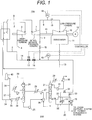
- Fig. 1 shows a schematic system block diagram of the thermal power plant including the carbon dioxide separation and capture apparatus of this embodiment.
- the steam turbine 100 includes a boiler 1 for burning fossil fuel to generate steam, a steam turbine having a high-pressure turbine 3, an intermediate-pressure turbine 7, and a low-pressure turbine 10 which are driven to rotate by the steam generated by the boiler 1, a generator 12 for converting the turning force of the steam turbine to electric power, a condenser 11 for condensing the steam for driving to rotate the steam turbine to water, and a water feed system 13 for feeding the feed water condensed to water by the condenser 11 to the boiler 1.
- the boiler 1 heats feed water fed from the condenser 11 by heat obtained by burning fossil fuel and generates high-temperature and high-pressure steam.
- the steam generated by the boiler 1 flows down through a main steam pipe 2, is fed to the high-pressure turbine 3, and is reduced in pressure due to power generated in the high-pressure turbine 3.
- the steam driving the high-pressure turbine 3 flows down through a high-pressure turbine exhaust pipe 4 and a cold reheat pipe 5, is returned again to the boiler 1, and is reheated to hot reheat steam by the boiler 1.
- the reheat steam reheated by the boiler 1 flows down through a hot reheat pipe 6 from the boiler, is fed to the intermediate-pressure turbine 7, and is reduced in pressure due to power generated in the intermediate-pressure turbine 7.
- the steam driving the intermediate-pressure turbine 7 flows down through a crossover pipe 9 which is a connection pipe for connecting the intermediate-pressure turbine 7 and the low-pressure turbine 10, is fed to the low-pressure turbine 10, and is further reduced in pressure due to power generated in the low-pressure turbine 10.
- the steam driving the low-pressure turbine 10 is fed to the condenser 11 and is cooled and condensed to water by the condenser 11.
- the condensate condensed to water by the condenser 11 flows down through the feed water pipe 13 as feed water and is fed again to the boiler 1.
- the high-pressure turbine 3, the intermediate-pressure turbine 7, the low-pressure turbine 10, and the generator 12 are connected to each other via a turbine rotor 41 and each electric power of the high-, intermediate-, and low-pressure turbines is transferred to the generator 12 via the turbine rotor 41 and is taken out as electric power.
- the carbon dioxide separation and capture apparatus 200 includes an absorber 24 for absorbing carbon dioxide contained in boiler exhaust gas discharged from the boiler 1 of the steam turbine 100 by an absorbing liquid, a desorber 21 for separating carbon dioxide from the absorbing liquid that has absorbed carbon dioxide at the absorber 24, and a reboiler 18 that feeds to the desorber 21 a heat source for generating steam and separating carbon dioxide from the absorbing liquid.
- the boiler 1 when burning fossil fuel such as coal, generates boiler exhaust gas containing carbon dioxide.
- the boiler exhaust gas generated by the boiler 1 flows down through a boiler exhaust gas pipe 34 from the boiler 1 and is fed to a feed gas blower 35 to increase the pressure.
- the boiler exhaust gas pressurized by the feed gas blower 35 is fed to a boiler exhaust gas cooler 36 to be cooled and then is fed to the absorber 24.
- Carbon dioxide in the boiler exhaust gas fed to the absorber 24 is absorbed in the absorbing liquid in the absorber 24, so that the boiler exhaust gas becomes processed gas containing no carbon dioxide.
- the processed gas flows down through an absorber exit boiler exhaust gas pipe 39 from the absorber 24, is fed to a stack 40, and is discharged into the atmosphere from the stack 40.
- boiler exhaust gas not passing through the carbon dioxide separation and capture process flows down through an exhaust gas by-pass pipe 38 branching from the boiler exhaust gas pipe 34 on the upstream side of the feed gas blower 35, joins the absorber exit boiler exhaust gas pipe 39, and is led to the stack 40.
- a by-pass butterfly valve 37 for controlling the flow rate of the exhaust gas by-pass pipe 38 is installed on the exhaust gas by-pass pipe 38. By controlling the opening angle of the by-pass butterfly valve 37, the flow rate of boiler exhaust gas by-passing the carbon dioxide separation and capture apparatus 200 is controlled.
- the rich absorbing liquid which absorbed carbon dioxide contained in the boiler exhaust gas in the absorber 24 and contains much of carbon dioxide is fed to a rich amine pump 25, is pressurized, then is fed to a rich/lean amine exchanger 26, and is heated up to about 100°C.
- the rich absorbing liquid heated by the rich/lean amine exchanger 26 is fed to the desorber 21, is further heated up to about 120°C to 130°C in the desorber 21, and separates carbon dioxide absorbed from the boiler exhaust gas.
- the carbon dioxide separated from the rich absorbing liquid is fed to a desorber exit gas cooler 29 from the desorber 21 and is cooled.
- the carbon dioxide cooled by the desorber exit gas cooler 29 is fed to a reflux drum 30 and moisture contained in the gas is separated.
- the carbon dioxide separated moisture in the reflux drum 30 flows down through the CO 2 exhaust pipe and is fed to a CO 2 liquefying and storing facility (not drawn).
- the moisture separated from the carbon dioxide separation and capture apparatus 200 in the reflux drum 30 is fed to a reflux pump 31 from the reflux drum 30 to be pressurized and is returned to the desorber 21.
- a part of the absorbing liquid in the desorber 21 is pulled out through a rich amine extract pipe 22 and is fed to the reboiler 18 of the carbon dioxide separation and capture apparatus 200.
- the absorbing liquid fed to the reboiler 18 of the desorber 21 is heated to steam in the reboiler 18.
- the absorbing liquid converted to steam in the reboiler 18 of the carbon dioxide separation and capture apparatus flows down through a heating steam return pipe 23 of the carbon dioxide separation and capture apparatus 200, is returned to the desorber 21, and is used as a heating source for the rich absorbing liquid.
- the steam discharged from the high-pressure turbine 3 and the extraction steam extracted from the intermediate-pressure turbine 7 are fed as a heating source and in the reboiler 18, the absorbing liquid is heated by the fed extraction steam to generate steam.
- the absorbing liquid that separated carbon dioxide in the desorber 21 is fed to the rich/lean amine exchanger 26 from the desorber 21 and exchanges heat with the rich absorbing liquid in the rich/lean amine exchanger 26 to be cooled.
- the absorbing liquid cooled in the rich/lean amine exchanger 26 is fed to a lean amine pump 27 to be pressurized and is fed to a lean amine trim cooler 28.
- the absorbing liquid fed to the lean amine trim cooler 28 is cooled and then is returned to the absorber 24.
- the carbon dioxide separation and capture apparatus 200 is structured so as to circulate between the absorber 24 and the desorber 21.
- the steam pipe system for feeding steam taken out from the high-pressure turbine 3 and the intermediate-pressure turbine 7 to the reboiler 18 will be explained below.
- the steam pipe system includes an extraction steam pipe 14 for connecting the high-pressure turbine exhaust pipe 4 and the reboiler 18 and an intermediate-pressure turbine exhaust pipe 8 connected to the extraction steam pipe 14 and the intermediate-pressure turbine 7.
- the high-pressure turbine exhaust pipe 4 for feeding steam discharged from the high-pressure turbine 3 to the boiler 1 is connected to the cold reheat pipe 5 and branches to the extraction steam pipe 14.
- the extraction steam pipe 14 branches further halfway, and one side branched is connected to the reboiler 18, and the other side is connected to a reclaimer 19.
- a pressure control valve 32 is installed and on the steam pipe of the extraction steam pipe 14 branching on the side of the reclaimer 19, a pressure control valve 33 is installed.
- the steam feed source switching device for switching the steam feed source for feeding steam to the reboiler 18 to switch between the high-pressure turbine 3 and the intermediate-pressure turbine 7 so as to satisfy the steam pressure requested by the reboiler 18 will be explained.
- the steam feed source switching device includes an extraction control valve 17 installed in the extraction steam pipe 14 and an extraction control valve 45 installed in the intermediate-pressure turbine exhaust pipe 8.
- a pressure control valve 16 for adjusting the pressure of the extraction steam to be fed to the reboiler 18 and the extraction control valve 17 for switching the heating source for feeding the extraction steam to the reboiler 18 are provided. So as to satisfy the steam pressure requested by the reboiler 18 while the steam turbine is under the partial load operation, by controlling the opening angles of the extraction control valve 17 and the extraction control valve 45 installed in the intermediate-pressure turbine exhaust pipe 8, the heating source for feeding the extraction steam to the reboiler 18 is switched between the exhaust gas of the high-pressure turbine 3 and the exhaust gas of the intermediate-pressure turbine 7. For example, when feeding from the intermediate-pressure turbine 7, the extraction control valve 17 is closed and the extraction control valve 45 is opened. Further, when feeding from the high-pressure turbine 3, the extraction control valve 17 is opened and the extraction control valve 45 is closed.
- the pressure regulation device for regulating the pressure of steam flowing down through the steam pipe system from the intermediate-pressure turbine 7 toward the reboiler 18 will be explained.
- the pressure control valve 15 is installed in the crossover pipe 9. By narrowing the opening angle of the pressure control valve 15, the pressure of the extraction steam of the intermediate-pressure turbine 7 on the upstream side can be increased. Therefore, the pressure control valve 15, while the steam turbine is under the partial load operation, so that the pressure of steam flowing down through the steam pipe system from the intermediate-pressure turbine 7 toward the reboiler 18 satisfies the steam pressure requested by the reboiler 18, is controlled in the opening angle.
- Fig. 2 shows the relationship between the necessary pressure for decomposing carbon dioxide by the reboiler 18 of the carbon dioxide separation and capture apparatus 200 and the steam pressure to be fed to the carbon dioxide separation and capture apparatus 200 from the side of the steam turbine 100.
- the request pressure of the carbon dioxide separation and capture apparatus 200 is almost fixed independently of the plant load.
- the pressure of fed steam from the side of the steam turbine 100 changes depending upon the plant load. Therefore, if the steam turbine is partially loaded, the fed gas pressure may be lowered than the necessary pressure of the carbon dioxide separation and capture apparatus 200.
- the plant load at this time will be called a switching load hereinafter.
- the fed gas pressure from the side of the steam turbine 100 to the carbon dioxide separation and capture apparatus 200 is insufficient.
- since carbon dioxide is separated from the absorbing liquid in the desorber 21, the steam pressure requested by the reboiler 18 is maintained constant. Therefore, in this state, the carbon dioxide separation and capture apparatus 200 cannot maintain its operation.
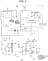
- Fig. 3 shows the schematic system block diagram of the thermal power plant including the carbon dioxide separation and capture apparatus in the case in which the crossover pipe 9 is not equipped with the pressure control valve 15.
- Fig. 4 shows the plant output and efficiency deviation characteristics of the thermal power plant including the carbon dioxide separation and capture apparatus in the case in which the crossover pipe 9 is not equipped with the pressure control valve 15 which is shown in Fig. 3 .
- Fig. 3 shows the schematic system block diagram of the thermal power plant including the carbon dioxide separation and capture apparatus in the case in which the crossover pipe 9 is not equipped with the pressure control valve 15.
- the axis of abscissas indicates the plant load and the axis of ordinates indicates the deviation rates of the output and efficiency at each load when the output and efficiency at the time of the rated load are assumed as plus or minus 0% and shows that in the lower portion of the axis of ordinates, the output and efficiency are lowered from those at the time of the rated load, that is, the deviation is large.
- Fig. 5 and 7 shows that in the lower portion of the axis of ordinates, the output and efficiency are lowered from those at the time of the rated load, that is, the deviation is large.
- the steam taken out from the intermediate-pressure turbine 7 is fed to the carbon dioxide separation and capture apparatus 200 from the intermediate-pressure turbine exhaust pipe 8 via the extraction steam pipe 14.
- the exhaust gas of the high-pressure turbine 3 is fed to the carbon dioxide separation and capture apparatus 200 from the cold reheat pipe 5 via the extraction steam pipe 14.
- Fig. 5 shows the plant output and efficiency deviation characteristics of the thermal power plant including the carbon dioxide separation and capture apparatus in the case in which the crossover pipe 9 is equipped with the pressure control valve 15.
- the output and efficiency deviations in the intermediate load zone are reduced.
- the fed steam feed source is the intermediate-pressure turbine exhaust pipe 8
- the steam after power generation by the intermediate-pressure turbine 7 is fed to the carbon dioxide separation and capture apparatus 200. Therefore, compared with the case that steam is fed from the cold reheat pipe 5 to the carbon dioxide separation and capture apparatus 200, the work of the intermediate-pressure turbine 7 is more, so that the output and efficiency deviations are reduced.
- the output and efficiency deviations are reduced.
- Fig. 7 which is a combination of Figs. 4 and 5 , the switching load can be reduced and the plant output and efficiency can be prevented from reduction. Further, in Fig. 7 , the output and efficiency deviation characteristics of this embodiment are shown by a solid line.
- the opening angle of the pressure control valve 15 installed in the crossover pipe 9 is totally opened and steam is fed from the intermediate-pressure turbine exhaust pipe 8.
- the pressure control valve 15 installed in the crossover pipe 9 is narrowed in the opening angle, the pressure reduction of the extraction steam flowing down through the intermediate-pressure turbine exhaust pipe 8 on the upstream side can be made smaller, so that in the intermediate load zone, by controlling (narrowing the opening angle available) the opening angle of the pressure control valve 15 installed in the crossover pipe 9, the fed gas pressure required by the carbon dioxide separation and capture apparatus 200 is maintained and steam is fed from the intermediate-pressure turbine exhaust pipe 8 to the carbon dioxide separation and capture apparatus 200.
- the opening angle of the pressure control valve 15 installed in the crossover pipe 9 is totally opened and, by using the extraction control valve 17 and the extraction control valve 45 which are a steam feed source switching device, the fed steam feed source is switched to the cold reheat pipe 5 on the side of the high-pressure turbine 3.
- the pressure control valve 15 is installed, thus the switching load can be reduced.
- the switching load is reduced, so that the generated energy by the intermediate-pressure turbine 7 in the intermediate load zone is increased, so that the output and efficiency deviations can be made smaller than the conventional ones.
- the opening angle of the pressure control valve 16 installed in the extraction steam pipe 14 which is a connection pipe between the cold reheat pipe 5 and the carbon dioxide separation and capture apparatus 200 is controlled (narrowing the opening angle available) so as to satisfy the necessary pressure on the side of the carbon dioxide separation and capture apparatus 200.
- Fig. 8 shows the opening angle characteristics of the pressure control valve 15 installed in the crossover pipe 9 and the pressure control valve 16 and the extraction control valve 17 which are installed in the cold reheat pipe 5.
- Table 1 shows a list summarizing the opening angle characteristics of the valves shown in Fig. 8 .
- Table 1 shows a list summarizing the opening angle characteristics of the valves shown in Fig. 8 .
- Table 1 Low load zone Intermediate load zone High load zone Pressure control valve 15 Totally opened Opening angle control Totally opened Pressure control valve 16 Opening angle control Totally closed Totally closed Extraction control valve 17 Totally opened Totally closed Totally closed
- the pressure control valve 15 In the high load zone while at the rated load operation, the pressure control valve 15 is totally opened and the pressure control valve 16 and the extraction control valve 17 are totally closed. In the intermediate load zone, the opening angle control for narrowing the opening angle of the pressure control valve 15 is performed and the pressure control valve 16 and the extraction control valve 17 are totally closed. Further, on the crossover pipe 9 on the upstream side of the pressure control valve 15, a pressure gauge 42 is installed and the opening angle control for the pressure control valve 15, by detecting the necessary pressure of the carbon dioxide separation and capture apparatus 200, controls the front pressure using the pressure value detected by the pressure gauge 42. In the low load zone, the pressure control valve 15 and the extraction control valve 17 are totally opened and the opening angle control for the pressure control valve 16 is performed.
- a pressure gauge 43 is installed on the downstream side of the pressure control valve 16 of the extraction steam pipe 14, and the pressure control valve 16 of the cold reheat pipe 5 controls the back pressure using the pressure value detected by the pressure gauge 43. Further, it is when the pressure set value of the pressure control valve 15 installed on the crossover pipe 9 becomes lower than the fed gas pressure set value to the carbon dioxide separation and capture apparatus 200 that switching the steam feed source for feeding steam to the carbon dioxide separation and capture apparatus 200 is made or that the extraction control valve 17 of the cold reheat pipe 5 is opened.
- the switching load generated when switching the feed source of steam to be fed to the reboiler 18 of the carbon dioxide separation and capture apparatus 200 between the intermediate-pressure turbine and the high-pressure turbine can be moved to a lower load zone than usual, the generated energy of the intermediate-pressure turbine can be increased. Therefore, in the case that the plant is partially loaded, it is possible to prevent the plant output and efficiency from reduction while ensuring the necessary pressure to the carbon dioxide separation and capture apparatus 200.
Landscapes
- Engineering & Computer Science (AREA)
- Chemical & Material Sciences (AREA)
- Mechanical Engineering (AREA)
- General Engineering & Computer Science (AREA)
- Combustion & Propulsion (AREA)
- Analytical Chemistry (AREA)
- General Chemical & Material Sciences (AREA)
- Oil, Petroleum & Natural Gas (AREA)
- Chemical Kinetics & Catalysis (AREA)
- Treating Waste Gases (AREA)
- Carbon And Carbon Compounds (AREA)
- Control Of Turbines (AREA)
Claims (7)
- Procédé de commande pour une centrale thermique comprenant :une chaudière (1) pour brûler un combustible fossile afin de générer de la vapeur,une turbine à vapeur (100) incluant une turbine à haute pression (3), et une turbine à pression intermédiaire (7), et une turbine à basse pression (10) qui sont entraînées par la vapeur générée dans la chaudière (1),un appareil de séparation et de capture de dioxyde de carbone (200) incluant un absorbeur (24) pour absorber et capturer du CO2 contenu dans les gaz d'échappement évacués de la chaudière (1) dans un liquide absorbant, un désorbeur (21) pour faire circuler le liquide absorbant entre le désorbeur (21) et l'absorbeur (24) et séparer le CO2 hors du liquide absorbant qui a absorbé le CO2, et un réchauffeur (18) pour fournir une source de chauffage afin de séparer le CO2 hors du liquide absorbant vers le désorbeur (21), etun système de tube à vapeur pour alimenter la vapeur prélevée de la turbine à haute pression (3) et de la turbine à pression intermédiaire (7) vers le réchauffeur (18), dans lequel :une source d'alimentation de vapeur pour alimenter de la vapeur au réchauffeur (18) est commandée de façon à commuter depuis la turbine à pression intermédiaire (7) vers la turbine à haute pression (3) quand la pression de la vapeur alimentée depuis la turbine à pression intermédiaire (7) vers le réchauffeur (18) est égale ou inférieure à la pression de la vapeur requise par le réchauffeur (18).
- Procédé de commande pour une centrale thermique selon la revendication 1, dans lequel :la turbine à vapeur (100) est dotée d'une valve de commande de pression (15) installée dans un tube pour alimenter la vapeur déchargée depuis la turbine à pression intermédiaire (7) vers la turbine à basse pression (10), et la valve de commande de pression (15) est commandée vis-à-vis d'un angle d'ouverture d'elle-même lorsque la turbine à vapeur (100) est dans un mode de fonctionnement à charge partielle, de sorte que la pression de la vapeur qui s'écoule via le système de tube à vapeur depuis la turbine à pression intermédiaire (7) vers le réchauffeur (18) satisfait une pression de vapeur requise par le réchauffeur (18).
- Procédé de commande pour une centrale thermique selon la revendication 1 ou 2, dans lequel :la valve de commande de pression (15) prévue dans le système de tube à vapeur est commandée vis-à-vis d'un angle d'ouverture d'elle-même, de sorte que la pression de la vapeur qui s'écoule depuis la turbine à haute pression (3) vers le réchauffeur (18) satisfait une pression de vapeur requise par le réchauffeur (18).
- Système comprenant :une chaudière (1) pour brûler un combustible fossile afin de générer de la vapeur,une turbine à vapeur (100) incluant une turbine à haute pression (3), une turbine à pression intermédiaire (7), et une turbine à basse pression (10) qui sont entraînées par la vapeur qui est générée dans la chaudière (1),un appareil de séparation et de capture de dioxyde de carbone (200) pour séparer et capturer le dioxyde de carbone hors des gaz d'échappement déchargés de la chaudière (1), auquel la vapeur est alimentée depuis la turbine à haute pression (3) et depuis la turbine à pression intermédiaire (7),un dispositif de commutation de source d'alimentation de vapeur, qui est installé pour commuter une source d'alimentation de vapeur destinée à alimenter de la vapeur à l'appareil de séparation et de capture de dioxyde de carbone (200) entre la turbine à haute pression (3) et la turbine à pression intermédiaire (7) de manière à satisfaire une pression de vapeur requise par l'appareil de séparation et de capture de dioxyde de carbone (200) lorsque la turbine à vapeur (100) est dans un mode de fonctionnement à charge partielle, etun dispositif de commande de pression prévu dans un tube (9) pour alimenter la vapeur évacuée de la turbine à pression intermédiaire (7) vers la turbine à basse pression (10) afin de réguler une pression de la vapeur alimentée depuis la turbine à pression intermédiaire (7) vers l'appareil de séparation et de capture de dioxyde de carbone (200).
- Système selon la revendication 4, dans lequel :le dispositif de commande de pression est doté d'une valve de commande de pression (15) et est configuré pour commander de façon à ouvrir totalement la valve de commande de pression lorsque la turbine à vapeur (100) est dans un mode de fonctionnement à charge nominale, etle dispositif de commande de pression est configuré pour commander un angle d'ouverture de la valve de commande de pression de telle façon que la pression de la vapeur alimentée depuis la turbine à pression intermédiaire (7) vers l'appareil de séparation et de capture de dioxyde de carbone (200) satisfait la pression de vapeur requise par l'appareil de séparation et de capture de dioxyde de carbone (200) lorsque la turbine à vapeur (100) est dans un mode de fonctionnement à charge partielle.
- Système selon l'une au moins des revendications 4 et 5, comprenant en outre :un système de tube à vapeur pour alimenter la vapeur prélevée de la turbine à haute pression (3) et de la turbine à pression intermédiaire (7) vers l'appareil de séparation et de capture de dioxyde de carbone (200),le dispositif de commutation de source de fourniture de vapeur est doté d'une valve de commutation installée dans le système de tube à vapeur, et le système de tube à vapeur est doté d'une valve de commande de pression (15) pour commander un angle d'ouverture de celle-ci, de sorte que la pression de la vapeur alimentée depuis la turbine à haute pression (3) vers l'appareil de séparation et de capture de dioxyde de carbone (200) satisfait la pression de vapeur requise par l'appareil de séparation et de capture de dioxyde de carbone (200).
- Centrale thermique comprenant le système selon l'une au moins des revendications 4 à 6.
Applications Claiming Priority (1)
| Application Number | Priority Date | Filing Date | Title |
|---|---|---|---|
| JP2011048484A JP5320423B2 (ja) | 2011-03-07 | 2011-03-07 | 火力発電プラント,蒸気タービン設備、およびその制御方法 |
Publications (2)
| Publication Number | Publication Date |
|---|---|
| EP2497561A1 EP2497561A1 (fr) | 2012-09-12 |
| EP2497561B1 true EP2497561B1 (fr) | 2017-11-15 |
Family
ID=45655827
Family Applications (1)
| Application Number | Title | Priority Date | Filing Date |
|---|---|---|---|
| EP12155569.2A Active EP2497561B1 (fr) | 2011-03-07 | 2012-02-15 | Système comprenant une centrale thermique ainsi qu'une turbine à vapeur ainsi qu'une méthode pour réguler ce système |
Country Status (3)
| Country | Link |
|---|---|
| US (1) | US8656719B2 (fr) |
| EP (1) | EP2497561B1 (fr) |
| JP (1) | JP5320423B2 (fr) |
Families Citing this family (17)
| Publication number | Priority date | Publication date | Assignee | Title |
|---|---|---|---|---|
| DE102009019334A1 (de) * | 2009-04-30 | 2010-11-04 | Rwe Power Ag | Verfahren zum Betrieb eines Dampfturbinenkraftwerks sowie Einrichtung zum Erzeugen von Dampf aus Braunkohle |
| JP5317833B2 (ja) * | 2009-05-28 | 2013-10-16 | 株式会社東芝 | 蒸気タービン発電設備 |
| JP5050071B2 (ja) * | 2010-03-29 | 2012-10-17 | 株式会社日立製作所 | ボイラ装置 |
| GB201010760D0 (en) * | 2010-06-28 | 2010-08-11 | Doosan Power Systems Ltd | Operation of steam turbine and steam generator apparatus with post-combustion carbon capture |
| JP5643691B2 (ja) * | 2011-03-23 | 2014-12-17 | 株式会社東芝 | 二酸化炭素回収型汽力発電システム及びその運転方法 |
| JP5885614B2 (ja) * | 2012-07-31 | 2016-03-15 | 株式会社東芝 | 蒸気タービンプラント、その制御方法、およびその制御システム |
| US9617874B2 (en) * | 2013-06-17 | 2017-04-11 | General Electric Technology Gmbh | Steam power plant turbine and control method for operating at low load |
| EP3026230A1 (fr) * | 2014-11-26 | 2016-06-01 | Siemens Aktiengesellschaft | Procédé de fonctionnement d'une unité de turbine, centrale à vapeur ou centrale à cycle combiné ainsi qu'utilisation d'un dispositif d'étranglement |
| US10375901B2 (en) | 2014-12-09 | 2019-08-13 | Mtd Products Inc | Blower/vacuum |
| US10690010B2 (en) * | 2018-03-16 | 2020-06-23 | Uop Llc | Steam reboiler with turbine |
| JP2019214975A (ja) * | 2018-06-13 | 2019-12-19 | 株式会社東芝 | ボイラ給水ポンプ駆動用タービンの駆動システム |
| JP7251720B2 (ja) * | 2018-06-19 | 2023-04-04 | ヤンマーパワーテクノロジー株式会社 | 二酸化炭素回収システム |
| JP7760483B2 (ja) | 2022-11-11 | 2025-10-27 | 三菱重工業株式会社 | 熱利用システム及び熱利用方法 |
| JP2024075964A (ja) * | 2022-11-24 | 2024-06-05 | 三菱重工業株式会社 | 二酸化炭素回収システム |
| JP2025005279A (ja) | 2023-06-27 | 2025-01-16 | 株式会社東芝 | 発電システムおよび発電方法 |
| CN117771922B (zh) * | 2024-02-26 | 2024-06-14 | 中国电力工程顾问集团华东电力设计院有限公司 | 一种全烟气二氧化碳捕集系统 |
| CN119771122B (zh) * | 2024-12-27 | 2025-07-18 | 广东华清双碳环境科技有限公司 | 一种基于ccus的烟气碳捕集系统 |
Citations (1)
| Publication number | Priority date | Publication date | Assignee | Title |
|---|---|---|---|---|
| EP2444141A1 (fr) * | 2010-10-21 | 2012-04-25 | Kabushiki Kaisha Toshiba | Procédé de récupération de dioxyde de carbone et système de génération d'énergie de vapeur de type à récupération de dioxyde de carbone |
Family Cites Families (9)
| Publication number | Priority date | Publication date | Assignee | Title |
|---|---|---|---|---|
| JPH10169411A (ja) * | 1996-12-13 | 1998-06-23 | Toshiba Corp | 蒸気タービンプラント |
| JP4274846B2 (ja) | 2003-04-30 | 2009-06-10 | 三菱重工業株式会社 | 二酸化炭素の回収方法及びそのシステム |
| JP4875303B2 (ja) | 2005-02-07 | 2012-02-15 | 三菱重工業株式会社 | 二酸化炭素回収システム、これを用いた発電システムおよびこれら方法 |
| US8062408B2 (en) * | 2006-05-08 | 2011-11-22 | The Board Of Trustees Of The University Of Illinois | Integrated vacuum absorption steam cycle gas separation |
| JP5317833B2 (ja) * | 2009-05-28 | 2013-10-16 | 株式会社東芝 | 蒸気タービン発電設備 |
| JP5484811B2 (ja) * | 2009-07-17 | 2014-05-07 | 三菱重工業株式会社 | 二酸化炭素の回収システム及び方法 |
| US20110120128A1 (en) * | 2009-11-20 | 2011-05-26 | Alstom Technology Ltd | Method of controlling a power plant |
| CA2722195C (fr) * | 2009-11-25 | 2013-03-19 | Hitachi, Ltd. | Centrale thermique a combustion de combustible fossile comprenant une unite de separation et de capture du dioxyde de carbone |
| JP5050071B2 (ja) * | 2010-03-29 | 2012-10-17 | 株式会社日立製作所 | ボイラ装置 |
-
2011
- 2011-03-07 JP JP2011048484A patent/JP5320423B2/ja active Active
-
2012
- 2012-01-05 US US13/344,435 patent/US8656719B2/en active Active
- 2012-02-15 EP EP12155569.2A patent/EP2497561B1/fr active Active
Patent Citations (1)
| Publication number | Priority date | Publication date | Assignee | Title |
|---|---|---|---|---|
| EP2444141A1 (fr) * | 2010-10-21 | 2012-04-25 | Kabushiki Kaisha Toshiba | Procédé de récupération de dioxyde de carbone et système de génération d'énergie de vapeur de type à récupération de dioxyde de carbone |
Also Published As
| Publication number | Publication date |
|---|---|
| EP2497561A1 (fr) | 2012-09-12 |
| JP5320423B2 (ja) | 2013-10-23 |
| US8656719B2 (en) | 2014-02-25 |
| JP2012184712A (ja) | 2012-09-27 |
| US20120227406A1 (en) | 2012-09-13 |
Similar Documents
| Publication | Publication Date | Title |
|---|---|---|
| EP2497561B1 (fr) | Système comprenant une centrale thermique ainsi qu'une turbine à vapeur ainsi qu'une méthode pour réguler ce système | |
| JP5317833B2 (ja) | 蒸気タービン発電設備 | |
| US8887505B2 (en) | Carbon dioxide recovery system and method | |
| US8776520B2 (en) | Method and device for operating a steam power station comprising a steam turbine and a process steam consumer | |
| CN102287244B (zh) | 二氧化碳捕集和压缩单元与蒸汽或者联合循环发电厂的热集成 | |
| EP2333255B1 (fr) | Centrale thermique à combustible fossile incluant une unité de séparation et de capture du dioxyde de carbone | |
| EP2625405B1 (fr) | Usine a cycle combiné et methode pour sa mise en oeuvre | |
| WO2011081040A1 (fr) | Système et procédé de récupération le dioxyde de carbone | |
| JP2009138748A (ja) | 排気ガスの再循環とco2の分離を行う複合サイクル発電所及びそのような複合サイクル発電所の動作方法 | |
| JP2008545945A (ja) | 蒸気発生設備および蒸気発生設備の運転方法とその追加装備方法 | |
| US20140033716A1 (en) | Steam turbine plant, control method of same, and control system of same | |
| US9617915B2 (en) | Method of increasing electricity output during high demand | |
| JP5355358B2 (ja) | 二酸化炭素分離回収装置を備えた化石燃料焚き火力発電システム | |
| US20160010511A1 (en) | Power generation system and method to operate |
Legal Events
| Date | Code | Title | Description |
|---|---|---|---|
| PUAI | Public reference made under article 153(3) epc to a published international application that has entered the european phase |
Free format text: ORIGINAL CODE: 0009012 |
|
| AK | Designated contracting states |
Kind code of ref document: A1 Designated state(s): AL AT BE BG CH CY CZ DE DK EE ES FI FR GB GR HR HU IE IS IT LI LT LU LV MC MK MT NL NO PL PT RO RS SE SI SK SM TR |
|
| AX | Request for extension of the european patent |
Extension state: BA ME |
|
| 17P | Request for examination filed |
Effective date: 20121011 |
|
| RAP1 | Party data changed (applicant data changed or rights of an application transferred) |
Owner name: MITSUBISHI HITACHI POWER SYSTEMS, LTD. |
|
| RAP1 | Party data changed (applicant data changed or rights of an application transferred) |
Owner name: MITSUBISHI HITACHI POWER SYSTEMS, LTD. |
|
| 17Q | First examination report despatched |
Effective date: 20150717 |
|
| STAA | Information on the status of an ep patent application or granted ep patent |
Free format text: STATUS: EXAMINATION IS IN PROGRESS |
|
| GRAP | Despatch of communication of intention to grant a patent |
Free format text: ORIGINAL CODE: EPIDOSNIGR1 |
|
| STAA | Information on the status of an ep patent application or granted ep patent |
Free format text: STATUS: GRANT OF PATENT IS INTENDED |
|
| INTG | Intention to grant announced |
Effective date: 20170529 |
|
| GRAS | Grant fee paid |
Free format text: ORIGINAL CODE: EPIDOSNIGR3 |
|
| GRAA | (expected) grant |
Free format text: ORIGINAL CODE: 0009210 |
|
| STAA | Information on the status of an ep patent application or granted ep patent |
Free format text: STATUS: THE PATENT HAS BEEN GRANTED |
|
| AK | Designated contracting states |
Kind code of ref document: B1 Designated state(s): AL AT BE BG CH CY CZ DE DK EE ES FI FR GB GR HR HU IE IS IT LI LT LU LV MC MK MT NL NO PL PT RO RS SE SI SK SM TR |
|
| REG | Reference to a national code |
Ref country code: CH Ref legal event code: EP Ref country code: GB Ref legal event code: FG4D Ref country code: AT Ref legal event code: REF Ref document number: 945710 Country of ref document: AT Kind code of ref document: T Effective date: 20171115 |
|
| REG | Reference to a national code |
Ref country code: IE Ref legal event code: FG4D |
|
| REG | Reference to a national code |
Ref country code: DE Ref legal event code: R096 Ref document number: 602012039681 Country of ref document: DE |
|
| REG | Reference to a national code |
Ref country code: NL Ref legal event code: FP |
|
| REG | Reference to a national code |
Ref country code: FR Ref legal event code: PLFP Year of fee payment: 7 |
|
| REG | Reference to a national code |
Ref country code: LT Ref legal event code: MG4D |
|
| REG | Reference to a national code |
Ref country code: AT Ref legal event code: MK05 Ref document number: 945710 Country of ref document: AT Kind code of ref document: T Effective date: 20171115 |
|
| PG25 | Lapsed in a contracting state [announced via postgrant information from national office to epo] |
Ref country code: SE Free format text: LAPSE BECAUSE OF FAILURE TO SUBMIT A TRANSLATION OF THE DESCRIPTION OR TO PAY THE FEE WITHIN THE PRESCRIBED TIME-LIMIT Effective date: 20171115 Ref country code: NO Free format text: LAPSE BECAUSE OF FAILURE TO SUBMIT A TRANSLATION OF THE DESCRIPTION OR TO PAY THE FEE WITHIN THE PRESCRIBED TIME-LIMIT Effective date: 20180215 Ref country code: LT Free format text: LAPSE BECAUSE OF FAILURE TO SUBMIT A TRANSLATION OF THE DESCRIPTION OR TO PAY THE FEE WITHIN THE PRESCRIBED TIME-LIMIT Effective date: 20171115 Ref country code: FI Free format text: LAPSE BECAUSE OF FAILURE TO SUBMIT A TRANSLATION OF THE DESCRIPTION OR TO PAY THE FEE WITHIN THE PRESCRIBED TIME-LIMIT Effective date: 20171115 Ref country code: ES Free format text: LAPSE BECAUSE OF FAILURE TO SUBMIT A TRANSLATION OF THE DESCRIPTION OR TO PAY THE FEE WITHIN THE PRESCRIBED TIME-LIMIT Effective date: 20171115 |
|
| PG25 | Lapsed in a contracting state [announced via postgrant information from national office to epo] |
Ref country code: AT Free format text: LAPSE BECAUSE OF FAILURE TO SUBMIT A TRANSLATION OF THE DESCRIPTION OR TO PAY THE FEE WITHIN THE PRESCRIBED TIME-LIMIT Effective date: 20171115 Ref country code: RS Free format text: LAPSE BECAUSE OF FAILURE TO SUBMIT A TRANSLATION OF THE DESCRIPTION OR TO PAY THE FEE WITHIN THE PRESCRIBED TIME-LIMIT Effective date: 20171115 Ref country code: BG Free format text: LAPSE BECAUSE OF FAILURE TO SUBMIT A TRANSLATION OF THE DESCRIPTION OR TO PAY THE FEE WITHIN THE PRESCRIBED TIME-LIMIT Effective date: 20180215 Ref country code: LV Free format text: LAPSE BECAUSE OF FAILURE TO SUBMIT A TRANSLATION OF THE DESCRIPTION OR TO PAY THE FEE WITHIN THE PRESCRIBED TIME-LIMIT Effective date: 20171115 Ref country code: GR Free format text: LAPSE BECAUSE OF FAILURE TO SUBMIT A TRANSLATION OF THE DESCRIPTION OR TO PAY THE FEE WITHIN THE PRESCRIBED TIME-LIMIT Effective date: 20180216 Ref country code: HR Free format text: LAPSE BECAUSE OF FAILURE TO SUBMIT A TRANSLATION OF THE DESCRIPTION OR TO PAY THE FEE WITHIN THE PRESCRIBED TIME-LIMIT Effective date: 20171115 |
|
| PG25 | Lapsed in a contracting state [announced via postgrant information from national office to epo] |
Ref country code: EE Free format text: LAPSE BECAUSE OF FAILURE TO SUBMIT A TRANSLATION OF THE DESCRIPTION OR TO PAY THE FEE WITHIN THE PRESCRIBED TIME-LIMIT Effective date: 20171115 Ref country code: DK Free format text: LAPSE BECAUSE OF FAILURE TO SUBMIT A TRANSLATION OF THE DESCRIPTION OR TO PAY THE FEE WITHIN THE PRESCRIBED TIME-LIMIT Effective date: 20171115 Ref country code: SK Free format text: LAPSE BECAUSE OF FAILURE TO SUBMIT A TRANSLATION OF THE DESCRIPTION OR TO PAY THE FEE WITHIN THE PRESCRIBED TIME-LIMIT Effective date: 20171115 Ref country code: CZ Free format text: LAPSE BECAUSE OF FAILURE TO SUBMIT A TRANSLATION OF THE DESCRIPTION OR TO PAY THE FEE WITHIN THE PRESCRIBED TIME-LIMIT Effective date: 20171115 Ref country code: CY Free format text: LAPSE BECAUSE OF FAILURE TO SUBMIT A TRANSLATION OF THE DESCRIPTION OR TO PAY THE FEE WITHIN THE PRESCRIBED TIME-LIMIT Effective date: 20171115 |
|
| REG | Reference to a national code |
Ref country code: DE Ref legal event code: R097 Ref document number: 602012039681 Country of ref document: DE |
|
| PG25 | Lapsed in a contracting state [announced via postgrant information from national office to epo] |
Ref country code: SM Free format text: LAPSE BECAUSE OF FAILURE TO SUBMIT A TRANSLATION OF THE DESCRIPTION OR TO PAY THE FEE WITHIN THE PRESCRIBED TIME-LIMIT Effective date: 20171115 Ref country code: PL Free format text: LAPSE BECAUSE OF FAILURE TO SUBMIT A TRANSLATION OF THE DESCRIPTION OR TO PAY THE FEE WITHIN THE PRESCRIBED TIME-LIMIT Effective date: 20171115 Ref country code: IT Free format text: LAPSE BECAUSE OF FAILURE TO SUBMIT A TRANSLATION OF THE DESCRIPTION OR TO PAY THE FEE WITHIN THE PRESCRIBED TIME-LIMIT Effective date: 20171115 Ref country code: RO Free format text: LAPSE BECAUSE OF FAILURE TO SUBMIT A TRANSLATION OF THE DESCRIPTION OR TO PAY THE FEE WITHIN THE PRESCRIBED TIME-LIMIT Effective date: 20171115 |
|
| REG | Reference to a national code |
Ref country code: DE Ref legal event code: R119 Ref document number: 602012039681 Country of ref document: DE |
|
| REG | Reference to a national code |
Ref country code: CH Ref legal event code: PL |
|
| PLBE | No opposition filed within time limit |
Free format text: ORIGINAL CODE: 0009261 |
|
| STAA | Information on the status of an ep patent application or granted ep patent |
Free format text: STATUS: NO OPPOSITION FILED WITHIN TIME LIMIT |
|
| PG25 | Lapsed in a contracting state [announced via postgrant information from national office to epo] |
Ref country code: MC Free format text: LAPSE BECAUSE OF FAILURE TO SUBMIT A TRANSLATION OF THE DESCRIPTION OR TO PAY THE FEE WITHIN THE PRESCRIBED TIME-LIMIT Effective date: 20171115 |
|
| 26N | No opposition filed |
Effective date: 20180817 |
|
| GBPC | Gb: european patent ceased through non-payment of renewal fee |
Effective date: 20180215 |
|
| REG | Reference to a national code |
Ref country code: IE Ref legal event code: MM4A |
|
| REG | Reference to a national code |
Ref country code: BE Ref legal event code: MM Effective date: 20180228 |
|
| PG25 | Lapsed in a contracting state [announced via postgrant information from national office to epo] |
Ref country code: SI Free format text: LAPSE BECAUSE OF FAILURE TO SUBMIT A TRANSLATION OF THE DESCRIPTION OR TO PAY THE FEE WITHIN THE PRESCRIBED TIME-LIMIT Effective date: 20171115 Ref country code: LI Free format text: LAPSE BECAUSE OF NON-PAYMENT OF DUE FEES Effective date: 20180228 Ref country code: LU Free format text: LAPSE BECAUSE OF NON-PAYMENT OF DUE FEES Effective date: 20180215 Ref country code: CH Free format text: LAPSE BECAUSE OF NON-PAYMENT OF DUE FEES Effective date: 20180228 |
|
| PG25 | Lapsed in a contracting state [announced via postgrant information from national office to epo] |
Ref country code: DE Free format text: LAPSE BECAUSE OF NON-PAYMENT OF DUE FEES Effective date: 20180901 Ref country code: IE Free format text: LAPSE BECAUSE OF NON-PAYMENT OF DUE FEES Effective date: 20180215 |
|
| PG25 | Lapsed in a contracting state [announced via postgrant information from national office to epo] |
Ref country code: BE Free format text: LAPSE BECAUSE OF NON-PAYMENT OF DUE FEES Effective date: 20180228 Ref country code: GB Free format text: LAPSE BECAUSE OF NON-PAYMENT OF DUE FEES Effective date: 20180215 |
|
| PG25 | Lapsed in a contracting state [announced via postgrant information from national office to epo] |
Ref country code: MT Free format text: LAPSE BECAUSE OF NON-PAYMENT OF DUE FEES Effective date: 20180215 |
|
| PG25 | Lapsed in a contracting state [announced via postgrant information from national office to epo] |
Ref country code: TR Free format text: LAPSE BECAUSE OF FAILURE TO SUBMIT A TRANSLATION OF THE DESCRIPTION OR TO PAY THE FEE WITHIN THE PRESCRIBED TIME-LIMIT Effective date: 20171115 |
|
| PG25 | Lapsed in a contracting state [announced via postgrant information from national office to epo] |
Ref country code: PT Free format text: LAPSE BECAUSE OF FAILURE TO SUBMIT A TRANSLATION OF THE DESCRIPTION OR TO PAY THE FEE WITHIN THE PRESCRIBED TIME-LIMIT Effective date: 20171115 Ref country code: HU Free format text: LAPSE BECAUSE OF FAILURE TO SUBMIT A TRANSLATION OF THE DESCRIPTION OR TO PAY THE FEE WITHIN THE PRESCRIBED TIME-LIMIT; INVALID AB INITIO Effective date: 20120215 |
|
| PG25 | Lapsed in a contracting state [announced via postgrant information from national office to epo] |
Ref country code: MK Free format text: LAPSE BECAUSE OF NON-PAYMENT OF DUE FEES Effective date: 20171115 |
|
| PG25 | Lapsed in a contracting state [announced via postgrant information from national office to epo] |
Ref country code: AL Free format text: LAPSE BECAUSE OF FAILURE TO SUBMIT A TRANSLATION OF THE DESCRIPTION OR TO PAY THE FEE WITHIN THE PRESCRIBED TIME-LIMIT Effective date: 20171115 Ref country code: IS Free format text: LAPSE BECAUSE OF FAILURE TO SUBMIT A TRANSLATION OF THE DESCRIPTION OR TO PAY THE FEE WITHIN THE PRESCRIBED TIME-LIMIT Effective date: 20180315 |
|
| REG | Reference to a national code |
Ref country code: NL Ref legal event code: HC Owner name: MITSUBISHI POWER, LTD.; JP Free format text: DETAILS ASSIGNMENT: CHANGE OF OWNER(S), CHANGE OF OWNER(S) NAME; FORMER OWNER NAME: MITSUBISHI HITACHI POWER SYSTEMS, LTD. Effective date: 20210114 |
|
| PGFP | Annual fee paid to national office [announced via postgrant information from national office to epo] |
Ref country code: FR Payment date: 20251231 Year of fee payment: 15 |
|
| PGFP | Annual fee paid to national office [announced via postgrant information from national office to epo] |
Ref country code: NL Payment date: 20260106 Year of fee payment: 15 |