EP2497569A2 - Procédés de distribution des fluides dans des dispositifs de micro-canaux multicanaux - Google Patents
Procédés de distribution des fluides dans des dispositifs de micro-canaux multicanaux Download PDFInfo
- Publication number
- EP2497569A2 EP2497569A2 EP20120000784 EP12000784A EP2497569A2 EP 2497569 A2 EP2497569 A2 EP 2497569A2 EP 20120000784 EP20120000784 EP 20120000784 EP 12000784 A EP12000784 A EP 12000784A EP 2497569 A2 EP2497569 A2 EP 2497569A2
- Authority
- EP
- European Patent Office
- Prior art keywords
- manifold
- flow
- channel
- dpr
- channels
- Prior art date
- Legal status (The legal status is an assumption and is not a legal conclusion. Google has not performed a legal analysis and makes no representation as to the accuracy of the status listed.)
- Withdrawn
Links
Images























Classifications
-
- B—PERFORMING OPERATIONS; TRANSPORTING
- B01—PHYSICAL OR CHEMICAL PROCESSES OR APPARATUS IN GENERAL
- B01J—CHEMICAL OR PHYSICAL PROCESSES, e.g. CATALYSIS OR COLLOID CHEMISTRY; THEIR RELEVANT APPARATUS
- B01J19/00—Chemical, physical or physico-chemical processes in general; Their relevant apparatus
- B01J19/0093—Microreactors, e.g. miniaturised or microfabricated reactors
-
- C—CHEMISTRY; METALLURGY
- C01—INORGANIC CHEMISTRY
- C01B—NON-METALLIC ELEMENTS; COMPOUNDS THEREOF; METALLOIDS OR COMPOUNDS THEREOF NOT COVERED BY SUBCLASS C01C
- C01B3/00—Hydrogen; Gaseous mixtures containing hydrogen; Separation of hydrogen from mixtures containing it; Purification of hydrogen; Reversible storage of hydrogen
- C01B3/02—Production of hydrogen; Production of gaseous mixtures containing hydrogen
- C01B3/32—Production of hydrogen; Production of gaseous mixtures containing hydrogen by reaction of gaseous or liquid organic compounds with gasifying agents, e.g. water, carbon dioxide or air
- C01B3/34—Production of hydrogen; Production of gaseous mixtures containing hydrogen by reaction of gaseous or liquid organic compounds with gasifying agents, e.g. water, carbon dioxide or air by reaction of hydrocarbons with gasifying agents
- C01B3/38—Production of hydrogen; Production of gaseous mixtures containing hydrogen by reaction of gaseous or liquid organic compounds with gasifying agents, e.g. water, carbon dioxide or air by reaction of hydrocarbons with gasifying agents using catalysts
- C01B3/384—Production of hydrogen; Production of gaseous mixtures containing hydrogen by reaction of gaseous or liquid organic compounds with gasifying agents, e.g. water, carbon dioxide or air by reaction of hydrocarbons with gasifying agents using catalysts with external heating of the catalyst
-
- F—MECHANICAL ENGINEERING; LIGHTING; HEATING; WEAPONS; BLASTING
- F15—FLUID-PRESSURE ACTUATORS; HYDRAULICS OR PNEUMATICS IN GENERAL
- F15D—FLUID DYNAMICS, i.e. METHODS OR MEANS FOR INFLUENCING THE FLOW OF GASES OR LIQUIDS
- F15D1/00—Influencing flow of fluids
- F15D1/001—Flow of fluid from conduits such as pipes, sleeves, tubes, with equal distribution of fluid flow over the evacuation surface
-
- F—MECHANICAL ENGINEERING; LIGHTING; HEATING; WEAPONS; BLASTING
- F15—FLUID-PRESSURE ACTUATORS; HYDRAULICS OR PNEUMATICS IN GENERAL
- F15D—FLUID DYNAMICS, i.e. METHODS OR MEANS FOR INFLUENCING THE FLOW OF GASES OR LIQUIDS
- F15D1/00—Influencing flow of fluids
- F15D1/02—Influencing flow of fluids in pipes or conduits
- F15D1/04—Arrangements of guide vanes in pipe elbows or duct bends; Construction of pipe conduit elements for elbows with respect to flow, e.g. for reducing losses of flow
-
- B—PERFORMING OPERATIONS; TRANSPORTING
- B01—PHYSICAL OR CHEMICAL PROCESSES OR APPARATUS IN GENERAL
- B01J—CHEMICAL OR PHYSICAL PROCESSES, e.g. CATALYSIS OR COLLOID CHEMISTRY; THEIR RELEVANT APPARATUS
- B01J2219/00—Chemical, physical or physico-chemical processes in general; Their relevant apparatus
- B01J2219/00781—Aspects relating to microreactors
-
- B—PERFORMING OPERATIONS; TRANSPORTING
- B01—PHYSICAL OR CHEMICAL PROCESSES OR APPARATUS IN GENERAL
- B01J—CHEMICAL OR PHYSICAL PROCESSES, e.g. CATALYSIS OR COLLOID CHEMISTRY; THEIR RELEVANT APPARATUS
- B01J2219/00—Chemical, physical or physico-chemical processes in general; Their relevant apparatus
- B01J2219/00781—Aspects relating to microreactors
- B01J2219/00783—Laminate assemblies, i.e. the reactor comprising a stack of plates
-
- B—PERFORMING OPERATIONS; TRANSPORTING
- B01—PHYSICAL OR CHEMICAL PROCESSES OR APPARATUS IN GENERAL
- B01J—CHEMICAL OR PHYSICAL PROCESSES, e.g. CATALYSIS OR COLLOID CHEMISTRY; THEIR RELEVANT APPARATUS
- B01J2219/00—Chemical, physical or physico-chemical processes in general; Their relevant apparatus
- B01J2219/00781—Aspects relating to microreactors
- B01J2219/00851—Additional features
- B01J2219/00858—Aspects relating to the size of the reactor
- B01J2219/0086—Dimensions of the flow channels
-
- B—PERFORMING OPERATIONS; TRANSPORTING
- B01—PHYSICAL OR CHEMICAL PROCESSES OR APPARATUS IN GENERAL
- B01J—CHEMICAL OR PHYSICAL PROCESSES, e.g. CATALYSIS OR COLLOID CHEMISTRY; THEIR RELEVANT APPARATUS
- B01J2219/00—Chemical, physical or physico-chemical processes in general; Their relevant apparatus
- B01J2219/00781—Aspects relating to microreactors
- B01J2219/00891—Feeding or evacuation
-
- B—PERFORMING OPERATIONS; TRANSPORTING
- B01—PHYSICAL OR CHEMICAL PROCESSES OR APPARATUS IN GENERAL
- B01J—CHEMICAL OR PHYSICAL PROCESSES, e.g. CATALYSIS OR COLLOID CHEMISTRY; THEIR RELEVANT APPARATUS
- B01J2219/00—Chemical, physical or physico-chemical processes in general; Their relevant apparatus
- B01J2219/00781—Aspects relating to microreactors
- B01J2219/00993—Design aspects
- B01J2219/00995—Mathematical modeling
-
- C—CHEMISTRY; METALLURGY
- C01—INORGANIC CHEMISTRY
- C01B—NON-METALLIC ELEMENTS; COMPOUNDS THEREOF; METALLOIDS OR COMPOUNDS THEREOF NOT COVERED BY SUBCLASS C01C
- C01B2203/00—Integrated processes for the production of hydrogen or synthesis gas
- C01B2203/02—Processes for making hydrogen or synthesis gas
- C01B2203/0205—Processes for making hydrogen or synthesis gas containing a reforming step
- C01B2203/0227—Processes for making hydrogen or synthesis gas containing a reforming step containing a catalytic reforming step
- C01B2203/0233—Processes for making hydrogen or synthesis gas containing a reforming step containing a catalytic reforming step the reforming step being a steam reforming step
-
- C—CHEMISTRY; METALLURGY
- C01—INORGANIC CHEMISTRY
- C01B—NON-METALLIC ELEMENTS; COMPOUNDS THEREOF; METALLOIDS OR COMPOUNDS THEREOF NOT COVERED BY SUBCLASS C01C
- C01B2203/00—Integrated processes for the production of hydrogen or synthesis gas
- C01B2203/08—Methods of heating or cooling
- C01B2203/0805—Methods of heating the process for making hydrogen or synthesis gas
- C01B2203/0811—Methods of heating the process for making hydrogen or synthesis gas by combustion of fuel
-
- C—CHEMISTRY; METALLURGY
- C01—INORGANIC CHEMISTRY
- C01B—NON-METALLIC ELEMENTS; COMPOUNDS THEREOF; METALLOIDS OR COMPOUNDS THEREOF NOT COVERED BY SUBCLASS C01C
- C01B2203/00—Integrated processes for the production of hydrogen or synthesis gas
- C01B2203/08—Methods of heating or cooling
- C01B2203/0805—Methods of heating the process for making hydrogen or synthesis gas
- C01B2203/0811—Methods of heating the process for making hydrogen or synthesis gas by combustion of fuel
- C01B2203/0822—Methods of heating the process for making hydrogen or synthesis gas by combustion of fuel the fuel containing hydrogen
-
- F—MECHANICAL ENGINEERING; LIGHTING; HEATING; WEAPONS; BLASTING
- F28—HEAT EXCHANGE IN GENERAL
- F28F—DETAILS OF HEAT-EXCHANGE AND HEAT-TRANSFER APPARATUS, OF GENERAL APPLICATION
- F28F2260/00—Heat exchangers or heat exchange elements having special size, e.g. microstructures
- F28F2260/02—Heat exchangers or heat exchange elements having special size, e.g. microstructures having microchannels
-
- F—MECHANICAL ENGINEERING; LIGHTING; HEATING; WEAPONS; BLASTING
- F28—HEAT EXCHANGE IN GENERAL
- F28F—DETAILS OF HEAT-EXCHANGE AND HEAT-TRANSFER APPARATUS, OF GENERAL APPLICATION
- F28F3/00—Plate-like or laminated elements; Assemblies of plate-like or laminated elements
- F28F3/08—Elements constructed for building-up into stacks, e.g. capable of being taken apart for cleaning
-
- Y—GENERAL TAGGING OF NEW TECHNOLOGICAL DEVELOPMENTS; GENERAL TAGGING OF CROSS-SECTIONAL TECHNOLOGIES SPANNING OVER SEVERAL SECTIONS OF THE IPC; TECHNICAL SUBJECTS COVERED BY FORMER USPC CROSS-REFERENCE ART COLLECTIONS [XRACs] AND DIGESTS
- Y02—TECHNOLOGIES OR APPLICATIONS FOR MITIGATION OR ADAPTATION AGAINST CLIMATE CHANGE
- Y02P—CLIMATE CHANGE MITIGATION TECHNOLOGIES IN THE PRODUCTION OR PROCESSING OF GOODS
- Y02P20/00—Technologies relating to chemical industry
- Y02P20/10—Process efficiency
-
- Y—GENERAL TAGGING OF NEW TECHNOLOGICAL DEVELOPMENTS; GENERAL TAGGING OF CROSS-SECTIONAL TECHNOLOGIES SPANNING OVER SEVERAL SECTIONS OF THE IPC; TECHNICAL SUBJECTS COVERED BY FORMER USPC CROSS-REFERENCE ART COLLECTIONS [XRACs] AND DIGESTS
- Y10—TECHNICAL SUBJECTS COVERED BY FORMER USPC
- Y10T—TECHNICAL SUBJECTS COVERED BY FORMER US CLASSIFICATION
- Y10T137/00—Fluid handling
- Y10T137/0318—Processes
-
- Y—GENERAL TAGGING OF NEW TECHNOLOGICAL DEVELOPMENTS; GENERAL TAGGING OF CROSS-SECTIONAL TECHNOLOGIES SPANNING OVER SEVERAL SECTIONS OF THE IPC; TECHNICAL SUBJECTS COVERED BY FORMER USPC CROSS-REFERENCE ART COLLECTIONS [XRACs] AND DIGESTS
- Y10—TECHNICAL SUBJECTS COVERED BY FORMER USPC
- Y10T—TECHNICAL SUBJECTS COVERED BY FORMER US CLASSIFICATION
- Y10T137/00—Fluid handling
- Y10T137/8593—Systems
- Y10T137/85938—Non-valved flow dividers
-
- Y—GENERAL TAGGING OF NEW TECHNOLOGICAL DEVELOPMENTS; GENERAL TAGGING OF CROSS-SECTIONAL TECHNOLOGIES SPANNING OVER SEVERAL SECTIONS OF THE IPC; TECHNICAL SUBJECTS COVERED BY FORMER USPC CROSS-REFERENCE ART COLLECTIONS [XRACs] AND DIGESTS
- Y10—TECHNICAL SUBJECTS COVERED BY FORMER USPC
- Y10T—TECHNICAL SUBJECTS COVERED BY FORMER US CLASSIFICATION
- Y10T436/00—Chemistry: analytical and immunological testing
- Y10T436/25—Chemistry: analytical and immunological testing including sample preparation
- Y10T436/2575—Volumetric liquid transfer
Definitions
- Microscale chemical processors which are characterized by fluid channel dimensions of about 5 mm or less, can provide unique advantages due to short heat and mass transfer distances, and, in some instances, different flow characteristics. Although these devices may offer many advantages, new designs and differing flow characteristics within these devices create challenges for creating new methods and designs for controlling flow, particularly flow through a manifold and several connecting channels.
- the small channel dimensions that give rise to improved heat and mass transport can often be in the laminar flow regime, which in turn carries a lower flow resistance than transition and turbulent flow regimes.
- a laminar regime can exist even for very high flow rates due to the small dimensions of the channels.
- a large microchannel processing device could have relatively small pressure drops at high overall flow rate, adding to the flow distribution challenge due to low flow resistance.
- microscale devices are connected to macro pipes to bring in and remove fluids. Flow in the macro-pipes is often in the turburlent or transition regime, thus requiring flow manifolding solutions within the microdevice that distribute flow to many parallel microchannels under varying flow regimes.
- the invention provides a method of separating phases, comprising: passing a mixture into a curve in a microchannel; wherein, after the curve, there is a separator plate in the microchannel; and wherein the micture separates into a denser phase and a less dense phase with the different phases on opposite sides of the separator plate.
- flow is down substantially parallel to gravity into the curve. The invention also provides this apparatus.
- the invention provides a fluid processor, comprising: a manifold comprising an inlet; a connecting channel matrix; and a gate disposed between the manifold and the connecting channel matrix.
- the length of the manifold and the length of the connecting channel matrix are disposed at a nonzero angle relative to each other.
- the connecting channel matrix served by the gate has a central axis; and the gate is offset so that the gate's opening is not bisected by the central axis of the connecting channel matrix.
- the length of the manifold is substantially perpendicular to the length of the connecting channels.
- the offset is at least 10% (in some preferred embodiments at least 25%) of the width of the connecting channel matrix.
- the invention also provides methods of processing a fluid comprising passage of at least one fluid through the apparatus.
- the manifold and connecting channel matrix can be coplanar; indeed substantially coplanar arrangements are common throughout many aspects of the present invention and it should be understood that a coplanar arrangement is preferred in many aspects of the invention.
- the invention is intended to include combinations of the various aspects and features described herein.
- the gates offsets described in the foregoing aspect are combined with the variance in the extension of connecting channel walls described in the aspect below.
- the invention is intended to include multiple combinations of the described individual features and should not be limited to only the illustrated combinations or the combinations that are described herein.
- the invention provides a fluid processor, comprising: a manifold comprising an inlet; and a connecting channel matrix.
- the length of the manifold and the length of the connecting channel matrix are disposed at a nonzero angle relative to each other.
- the connecting channel matrix comprises multiple channel walls and channel walls further from the inlet extend further toward the manifold.
- the length of the manifold is substantially perpendicular to the length of the connecting channels; and/or, the offset is at least 10% (in some preferred embodiments at least 25%) of the width of the connecting channel matrix.
- the invention provides a method of passing a fluid through a manifold of a microchannel device, comprising: flowing a first fluid stream through a first channel in a first direction; flowing a portion of the first fluid stream through an aperture to a second channel; and flowing a portion of the first fluid stream through the second channel; wherein the second channel extends at a nonzero angle relative to the first direction; wherein flow through the aperture has a positive momentum vector in the first direction; wherein the second channel comprises a microchannel and comprises at least one dividing wall that separates the second channel into at least a first and a second subchannel; wherein the second channel has an axis that is substantially parallel to net flow through the second channel; and wherein the aperture has a centerpoint that lies upstream of the axis relative to the first direction.
- flow in the first and second subchannels is more equal than if the axis passed through the centerpoint.
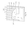
- a preferred structure in which this method can be conducted is illustrated in Fig. 24 .
- the invention provides a method of passing a fluid through a manifold of a microchannel device, comprising: flowing a first fluid stream through a first channel in a first direction; flowing a portion of the first fluid stream through an aperture to a second channel; and flowing a portion of the first fluid stream through the second channel.
- the second channel comprises a microchannel and comprises at least one dividing wall that separates the second channel into at least a first and a second subchannel.
- the first and second subchannels comprise flow resistors that tend to equalize flow through the subchannels.
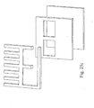
- a structure suitable for conducting this method is illustrated in Fig. 25b .
- the invention also includes the apparatus in which the method is conducted.
- the second channel extends at a nonzero angle relative to the first direction.
- the method can be conducted in a laminated device with frames or strips; and/or flow resistors (such as a foam); and/or where there is no straight through flow path; and/or where there is a discontinuity in the dividing wall downstream along the length of the dividing wall.
- the manifold and connecting channels are substantially coplanar.
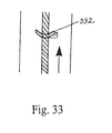
- the invention provides microchannel apparatus, comprising at least two microchannels separated by a wall; and a flexible material projecting from the wall into at least into at least one of the microchannels. See Fig. 33 . "Flexible" means that the material flexes when fluid flows through the microchannel. In one embodiment, the material extends through the wall into a second microchannel.
- the invention provides microchannel apparatus, comprising: a first channel extending in a first direction; and a second channel extending in a second direction.
- the first direction and second direction are substantially coplanar and extend at a nonzero angle relative to each other;
- the second channel comprises a microchannel; and
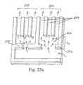
- the second channel comprises a first open portion and a second portion that comprises at least one dividing wall that separates the second channel into at least a first and a second subchannel.
- the first open portion provides for a length for flow to distribute more equally across the stream prior to entering the second portion.
- "Open" means no subchannels. An example is illustrated in Fig. 25a .
- the invention also includes methods of processing a fluid in this apparatus, preferably in which mixing occurs in the first portion.
- L 2 /D is greater than 10, where D is hydraulic diameter.
- the subchannels are connecting channels in which a unit operation occurs.
- microchannel apparatus comprising:
- the invention provides microchannel apparatus including a submanifold, comprising: a first channel comprising at least one dividing wall that separates the first channel into at least a first and a second subchannel; the first channel extending in a first direction; a second channel connected to the first subchannel; wherein the second channel is substantially coplanar with the first channel and extends in a second direction; wherein the second direction is at a nonzero angle relative to the first direction; wherein the second channel comprises a microchannel and comprises at least one dividing wall that separates the second channel into at least a third and a fourth subchannel; a third channel connected to the second subchannel; wherein the third channel is substantially coplanar with the first channel and extends in a third direction; wherein the third direction is parallel to the second direction; wherein the third channel comprises a microchannel and comprises at least one dividing wall that separates the third channel into at least a fifth and a sixth subchannel; wherein the first subchannel has a first length and a first width and the second
- the first channel comprises a first portion with no channel wall and a second portion that comprises the at least one dividing wall that separates the first channel into at least a first and a second subchannel; and the second width is wider than the first width.
- Some preferred embodiment comprise gates.
- a fourth channel ia connected to the second subchannel; wherein the fourth channel is substantially coplanar with the first channel and extends in a fourth direction; wherein the fourth direction is at a nonzero angle relative to the first direction; wherein the fourth channel comprises a microchannel and comprises at least one dividing wall that separates the second channel into at least a seventh and an eighth subchannel; wherein the fourth direction is parallel to the second direction; and wherein the fourth channel has a fourth length that is longer than the second length.
- the invention provides microchannel apparatus including a gated structure, comprising: a first channel extending in a first direction; a second channel extending in a second direction; and a third channel extending in the second direction; a fourth channel extending in the second direction; and a fifth channel extending in the second direction.
- the first and second directions are substantially coplanar.
- the second and third channels are adjacent and parallel.
- the first channel is not parallel to either the second or third channels.
- the first channel is connected to the second channel and the third channels via a first gate.
- the third channel is positioned farther in the first direction than the second channel.
- the third channel comprises a microchannel.
- the second channel comprises a microchannel.
- the second channel has an opening with a first cross-sectional area and the third channel has an opening with a second cross-sectional area.
- the first gate has a cross-sectional area that is smaller than the sum of first and second cross-sectional areas and the wall cross-sectional area between them.
- the fourth and fifth channels are adjacent and parallel. The first channel is connected to the fourth channel and the fifth channels via a second gate. The fourth and fifth channels are positioned farther in the first direction than the third channel.
- the fourth channel comprises a microchannel; wherein the fifth channel comprises a microchannel.
- the fourth channel has an opening with a third cross-sectional area and the fifth channel has an opening with a fourth cross-sectional area.
- the second gate has a cross-sectional area that is smaller than the sum of third and fourth cross-sectional areas and the wall cross-sectional area between them; and the cross-sectional area of the first gate differs from that of the cross-sectional area of the second gate.
- the first gate has a cross-sectional area between 2-98% of the combined cross-sectional areas of the connecting microchannels served by the first gate.
- the apparatus is a laminate and the first gate comprises a sheet with a cross-bar.
- microchannel apparatus comprising:
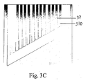
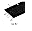
- the invention provides a laminated device, comprising: a first layer comprising microchannels that end in a first crossbar; and a second layer comprising microchannels that end in a second crossbar; wherein the first crossbar defines at least a portion of one edge of an M2M manifold; wherein the second crossbar projects into the M2M manifold; and wherein an interface between the microchannels in the second layer and the manifold is formed by an open gap between the first and second crossbars.
- Fig. 3D An example is shown in Fig. 3D .
- the first layer is adjacent to the second layer.
- the device includes microchannels in first and second layers that are aligned.
- the laminated device further comprises: a second set of microchannels in the first layer that end in a third crossbar; and a second set of microchannels in the second layer that end in a fourth crossbar; wherein the third crossbar defines at least a portion of one edge of the M2M manifold; wherein the fourth crossbar projects into the M2M manifold; wherein a second interface between the microchannels in the fourth layer and the manifold is formed by an open gap between the third and fourth crossbars; and wherein the open gap between the third and fourth crossbars is smaller than the open gap between the first and second crossbars.
- the differing gap size allows systems to be designed to control flow though the microchannels (i.e., function like a gate); for example to make flow more equal than if the gaps were equal.
- Systems including a macromanifold connected to at least two of the laminated devices and methods of conducting a unit operation comprising passing a fluid into the manifold and through the microchannels, are, of course, included.
- the invention provides a method of distributing flow from a manifold through a connecting channel matrix, comprising:
- the invention provides a method of distributing flow from a manifold through a connecting channel matrix, comprising:
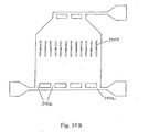
- the invention provides a louvered fluid processing device, comprising: an inlet to a chamber; a louver disposed within a chamber; and an outlet from the chamber.
- a louver is a movable flow director.
- FIG. 34B An example is illustrated in Fig. 34B .
- Other options include: at least 3 coplanar inlets; further comprising a second chamber that is stacked adjacent to the chamber, wherein the first chamber comprises a heat exchanger.
- flows are substantially perpendicular to flow through the heat exchanger biased to front of second (reaction) chamber.
- the chamber has height of 5 micrometers or less.
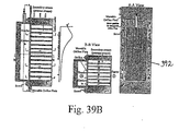
- the invention provides fluid processing apparatus comprising: a manifold; a connecting channel matrix; and a movable orifice plate disposed between the manifold and the matrix, wherein the movable orifice plate has orifices of varying sizes that are aligned with channels in the connecting channel matrix.
- a manifold a connecting channel matrix
- a movable orifice plate disposed between the manifold and the matrix, wherein the movable orifice plate has orifices of varying sizes that are aligned with channels in the connecting channel matrix.
- An example is illustrated in Fig. 39 .
- the movable orifice plate is held in place by screws.
- the movable plate has orifices that increase monotonically in size along the length of the plate.
- channels in the connecting channel matrix have the same cross-scetional area.
- the invention also provides a method of modifying a fluid processing apparatus comprising moving the position of a movable orifice plate in the above-described apparatus.
- the invention provides a method of distributing flow from a manifold through a connecting channel matrix, comprising: passing a fluid through a manifold and into a connecting channel matrix, wherein the connecting channel matrix comprises repeating units of microchannels of differing cross-sectional areas, and wherein the manifold has an inlet disposed on one side of the connecting channel matrix so that fluid flow through the manifold is at a nonzero angle to flow in the connecting channel matrix; wherein the connecting channels in two or more repeating units do not change in cross-sectional area in the direction of length through the manifold; and wherein a fluid flows into the manifold with a momentum (Mo) of at least 0.05; and is distributed through the connecting channel matrix with a Q 2 of less than 30%, preferably Q 2 is less than 25%, and more preferably less than 10%.
- Mo momentum
- “Repeating units” are a coplanar set of adjacent channels of differing cross-sectional areas that repeat. For example, a first channel having a cross-sectional area of 1 um 2 adjacent to a second channel having a cross-sectional area of 2 um 2 which is, in turn, adjacent to a third channel having a cross-sectional area of 3 um 2 ; This sequence repeated three times: 1:2:3/1:2:3/1:2:3 would be three repeating units.
- the manifold is substantially perpendicular to the connecting channels.
- the invention provides a method of distributing flow from a manifold through a connecting channel matrix, comprising: passing a fluid through a manifold inlet and into a manifold such that the fluid passes through a first portion of a manifold in a first flow regime and passes through a second portion of a manifold in a second flow regime; wherein the manifold has a height of the manifold (h m2m ) of 2mm or less and a length of an optional straightening channel portion (L 2 ) divided by L m2m of less than 6.
- the DPR 2 ratio remains at 2 or greater or the DPR 3 ratio remains at 0.9 or less.
- the first flow regime is turbulent and second flow regime is transitional.
- R a is equal to or less than 12.
- the fluid passes through a macromanifold and then passes through the manifold inlet.
- the invention provides a method of passing a fluid through a manifold of a microchannel device, comprising: flowing a first fluid stream into a manifold and then through a first channel in a first direction; flowing a portion of the first fluid stream to a second channel; and flowing a portion of the first fluid stream through the second channel.
- the second channel extends at a nonzero angle relative to the first direction;
- the second channel comprises a microchannel and comprises at least one dividing wall that separates the second channel into at least a first and a second subchannel;
- the first layer and the manifold are each substantially planar; wherein the manifold is substantially contained within the first layer, and wherein the first layer and the manifold are substantially coplanar, and the first channel is disposed in the first layer and flow through the first channel is substantially parallel to the plane of the first layer; the first channel and the manifold are about the same height;
- the second layer is substantially planar, the second channel is disposed in the second layer and flow through the second channel is substantially parallel to the plane of the second layer; and the first layer and the second layer are substantially parallel and the nonzero angle refers to an angle within the second layer.
- the second layer is adjacent (i.e., no intervening layers) to the first layer and the only flow into the second layer is from the first layer.
- a plate comprising an opening is disposed between the first and second layers and flow from the first layer passes through the opening into the second layer.
- the first layer includes multiple adjacent parallel microchannels which are separated by channel walls; and the second layer comprises multiple adjacent parallel microchannels separated by continuous channel walls wherein the continuous channel walls traverse the width of the multiple adjacent parallel microchannels in the first layer.
- the second layer can be made from a sheet containing slots.
- the first layer comprises multiple adjacent parallel microchannels separated by channel walls; and the second layer comprises multiple adjacent parallel microchannels separated by continuous channel walls; and a portion of the flow through the first layer passes into the second layer where it is redistributed into the microchannels in the first layer.
- the presence of the second layer tends to equalize flow through the multiple adjacent parallel microchannels in the first layer; this means that there is a lower Q than if not present; (as with any of the other methods, Q could be any of the preferred Qs described herein.
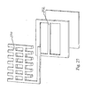
- the multiple adjacent parallel microchannels comprise a crossbar that forces flow into the second layer; and, other than contact with the first layer, the second layer does not have any inlets or outlets (an example is illustrated in Fig. 27 ).
- the invention includes the apparatus of this method.
- the invention provides a system (and corresponding methods utilizing the system) in which a macromanifold connects two or more microdevices, where each microdevice has an M2M as described herein.
- a "macromanifold" is a manifold that connects to at least two smaller manifolds.
- a macromanifold can be a pipe (outside of a microchannel device) that connects to two or more M2M manifolds that are within a microchannel device.
- These systems may include, for example, one macro pipe or duct to two or more devices with M2M regions, then to two or more submanifolds in each device, then optionally to two or more connecting channels from each submanifold.
- Another example of a system includes, for example, a macropipe or duct, connected to two or more devices with M2M regions, then to two or more submanifolds, then finally to two or more connecting channels, or one device including an M2M, to two or more submanifolds, then to two or more connecting channels, then to subchannels within the connecting channels created by a fin structure.
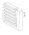
- the invention provides a method of passing a fluid through the manifold of a microchannel fluid processing device, comprising: passing a first fluid through a first inlet into a first manifold zone; passing a second fluid through a second inlet into a second manifold zone; wherein a wall is disposed between the first and second manifold zones, and wherein the wall comprises openings that permit mixing of the first and second fluids in the manifold; wherein the manifold is adjacent to a connecting channel matrix; forming a mixed fluid by combining the first and second fluids in the manifold; and wherein the mixed fluid passes into the connecting channel matrix.
- An example of this aspect is illustrated in Fig. 28 .
- the invention provides a microchannel fluid processing device, comprising: a manifold connected to a connecting channel matrix; wherein the manifold and connecting channel matrix are coplanar; and further comprising a flow directing feature that comprises: an inclined manifold; or angled connections that connect the manifold and the connecting channel matrix.
- the angled connections if present, comprise angles in the range from 10 to 80, or 100 to 170 degrees, relative to the central axis through the manifold.
- the angled connections that connect the manifold and the connecting channel matrix comprise angles in the range from 10 to 80 in the first half of the length of the manifold, and 100 to 170 degrees in the second half of the length of the manifold, relative to the central axis through the manifold.
- a preferred embodiment has the manifold inclined so that manifold volume decreases with increasing length away from a manifold inlet. In some embodiments, these features are etched into a substrate.
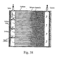
- the invention provides a microchannel device, comprising: a manifold; a connecting channel matrix; at least three orifice plates disposed in the manifold such that flow through the entire manifold would pass through all of said at least three orifice plates.
- the at least three orifice plates have orifices with differing cross-sectional areas; and the orifice plates divide the manifold into segments, wherein each segment is connected to at least one connecting channel in a connecting channel matrix.
- An example is illustrated in Fig. 38 .
- the orifice area in the three plates decrease with increasing length down the manifold.
- Other preferred embodiments comprise grates and/or gates.
- the heights of connecting channels and/or manifolds are preferably in the range of 20 ⁇ m to 5 mm, more preferably 2 mm or less.
- the thickness of walls separating channels or manifold walls are preferably in the range of 20 ⁇ m to 5 mm, more preferably 2 mm or less.
- Connecting channels preferably have a length of 1 cm to 10 m
- the web thickness between layers is preferably the thickness of a sheet (in other words, in some preferred embodiments, devices are made by cutting features through a sheet rather than etching).
- the connecting channels are substantially parallel to the manifold to which the channels are connected.
- desired flow distributions can be achieved in microdevices containing multiple connecting channels fed by a manifold (or single connecting channels fed from a very high connecting channel aspect ratio manifold); and these desired flow distributions can be obtained even in high momentum conditions.
- the momentum number, Mo is preferably at least 0.1, more preferably at least 0.2, in some embodiments, at least 0.5 and in some embodiments at least 5.
- the manifold has an M2M manifold aspect ratio (defined below) of at least 10, or at least 20, or 50, or at least 100, and in some embodiments in the range of 30 to 1000.
- FA defined below
- FA is 0.01 or less and more preferably less than 0.001.
- flow through the majority (by volumetric flow) of the connecting channels has a Reynolds number of 10,000 or less, 5000 or less, 2000 or less, 1000 or less, and in some embodiments, in the range of 500 to 5000.
- at least two, more preferably at least 5, in some embodiments at least 10 or at least 100 or, in some embodiments, 5 to 500 connecting channels are served by a single M2M manifold.
- flow is controlled to be distributed equally over multiple connecting channels with Q factors (as described below) of 30% or less, more preferably 20% or less, and in some embodiments, in the range of 0.1% to 15%.
- the laminated devices are chemical reactors that are capable of processing fluid streams.
- the invention also includes devices having any of the structural features or designs described herein.
- the invention includes a device having exothermic reaction channels in an interleaved relationship with coolant and/or endothermic reaction channels; and having one or more flow modifiers in the reaction channels and/or being comprised of subassemblies at right angles to each other.
- aspects of the invention are combined; for example, any of the catalysts described herein may be selected to be incorporated into a reaction channel in any of the laminate designs described herein.
- the invention also includes laminated devices made by the method.
- the invention also includes processes of conducting a unit operation (or operations) using any of the devices, structural features, designs or systems described herein.
- the use of the fabrication techniques described herein can be applied to all devices for all chemical unit operations, including chemical reactors, combustors, separators, heat exchangers, vaporizers, evaporators, and mixers.
- the applications may include both gaseous and liquid fluid processing or combinations of the two phases.
- Liquid fluid processing may also include the generation of suspended solids in continuous liquid fluid phases, such as the formation of an emulsion.
- any of the articles described herein may have multiple layers and repeating sets of layers (repeating units). For example, 2, 10, 50 or more repeating units within a laminate. This multiplicity, or "numbering up" of layers creates added capacity of microchannel laminated devices.
- Various embodiments of the present invention may possess advantages such as: lower costs, more equal flow distribution in a multichannel array, lower manifold pressure drop, or additional heat transfer.
- a device comprises a lamina, a sheet, etc.
- inventive device may include multiple laminae, sheets, etc.
- the "channel axis" is the line through the center of a channel's cross-section as it extends through the channel.
- Binding means attaching or adhering, and includes diffusion bonding, gluing, brazing and welding.
- a “bump” is an obstruction or area of increased channel wall roughness that reduces mass flow rate through a channel under typical operating conditions.
- the total volume of the manifold does not include the channel walls in the layers directly above or below the manifold channel.
- the external containment wall volume in an M2M manifold includes that volume that separates the manifold from the necessary device perimeter of a microchannel device, which occurs around the entire device. It includes the wall volume separating the channels of fractal distribution manifolds that aren't used by other connecting channels.
- an M2M distributes 1 kg/m 3 /s, preferably 10 kg/m 3 /s, and in some preferred embodiments distributes 30 to 150 kg/m 3 /s.
- connections between the manifold and the connecting channels (i.e., the M2M distribution structures) described herein preferably have thicknesses (i.e., heights) of 20 ⁇ m to 5 mm, more preferably 2 mm or less, and preferably have widths in the range of 100 ⁇ m to 5 cm and in some preferred embodiments have widths more than 250 micrometers and less than one millimeter.
- the lengths ofthe connecting channels have a lower limit of zero and an upper limit of 1 meter, and in some preferred embodiments a range of 2 millimeters to 10 cm.
- the cross-sectional area of a channel is that cross-sectional plane normal to the channel axis. It excludes the cross-sectional area of the wall and any applied coatings (catalyst, bonding, metal protection) to the wall.
- a layer typically includes plural channels that are separated by channel walls.
- the cross-sectional area of a channel includes area taken up by catalyst, if present.
- Channels are defined by channel walls that may be continuous or may contain gaps. Interconnecting pathways through a monolith foam or felt are not connecting channels (although a foam, etc. may be disposed within a channel).
- Connecting channels are channels connected to a manifold. Typically, unit operations occur in connecting channels. Connecting channels have an entrance cross-sectional plane and an exit cross-sectional plane. Although some unit operations or portions of unit operations may occur in a manifold, in preferred embodiments, greater than 70% (in some embodiments at least 95%) of a unit operation occurs in connecting channels.
- a "connecting channel matrix” is a group of adjacent, substantially parallel connecting channels. In preferred embodiments, the connecting channel walls are straight.
- connection to manifold cross-sectional area ratio is the ratio of the cross-sectional area of open area of the manifold connection (such as a gate or grate) to the cross-sectional area (perpendicular to the central axis) of the manifold at the position immediately upstream of the connection (for a header) or immediately downstream of a connection (for a footer).
- the connecting channel pressure drop ( ⁇ P CCdP ) is the static pressure difference between the center of the entrance cross-sectional plane and the center of the exit cross-sectional plane of the connecting channels.
- connecting channels are straight with substantially no variation in direction or width.
- the connecting channel pressure drop for a system of multiple connecting channels is the arithmetic mean of each individual connecting channel pressure drop. That is, the sum of the pressure drops through each channel divided by the number of channels.
- pressure drops are unadjusted; however, in the claims, pressure are defined based on the channels that comprise 95% of the net flow through the connecting channels, the lowest flow channels are not counted if the flow through those channels is not needed to account for 95% of the net flow.
- the header manifold Reynolds number and hydraulic diameter for FA are defined at the position on the channel axis where the wall plane closest to the header entrance belonging to the connecting channel closest to the entrance in the manifold connects with the channel axis.
- the footer manifold Reynolds number and hydraulic diameter for FA are defined at the position where the wall plane closest to the footer exit belonging to the connecting channel closest to footer exit connects with the channel axis.
- FA should be below 0.01 and for some preferred embodiments less than 0.001.
- a “flow resistor” is a bump, grate, or porous body.
- a flow resistor is not a simple straight channel, and is not a gate at the start of a channel.
- a "footer” is a manifold arranged to take away fluid from connecting channels.
- a “gate” comprises an interface between the manifold and two or more connecting channels.
- a gate has a nonzero volume.
- a gate controls flow into multiple connecting channels by varying the cross sectional area of the entrance to the connecting channels.
- a gate is distinct from a simple orifice, in that the fluid flowing through a gate has positive momentum in both the direction of the flow in the manifold and the direction of flow in the connecting channel as it passes through the gate. In contrast, greater than 75% of the positive momentum vector of flow through an orifice is in the direction of the orifice's axis.
- a typical ratio of the cross sectional area of flow through a gate ranges between 2-98% (and in some embodiments 5% to 52%) of the cross sectional area of the connecting channels controlled by the gate including the cross sectional area of the walls between the connecting channels controlled by the gate.
- the use of two or more gates allows use of the manifold interface's cross sectional area as a means of tailoring manifold turning losses, which in turn enables equal flow rates between the gates. These gate turning losses can be used to compensate for the changes in the manifold pressure profiles caused by friction pressure losses and momentum compensation, both of which have an effect upon the manifold pressure profile.
- the maximum variation in the cross-sectional area divided by the minimum area, given by the Ra number is preferably less than 8, more preferably less than 6 and in even more preferred embodiments less than 4.
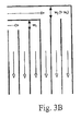
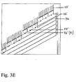
- a gate comprises two or more adjoining shims that have channel walls 32' connected at their respective ends. These end wall connections 34' fix the channel walls in space so that the ends do not move during manufacturing and handling. At least one shim has end wall connections continuous across the width of the gate's two or more connecting channels and walls to form the perimeter edge of the manifold 34'. The end wall connection in this shim creates a barrier for fluid flow between the manifold 36 and the two or more connecting channels 35'.
- the illustrated shim also has an intermediate wall connection 37' between the connecting channels and the end wall connections. The plane extending in the stacking direction from wall 37' is the connecting channel plane exit or entrance.
- the intermediate wall connection acts as a barrier for flow between the gate's two or more connecting channels, leaving an open volume between connections for flow distribution in the connection 38'.
- At least one other shim (the "gate opening" shim) has, where it interfaces the manifold perimeter, the end wall connection 42' only partially continuous across the width of the gate's two or more connecting channels and walls.
- There is one continuous section 44' of the end wall channel that is offset from the manifold perimeter, extending from the manifold 36' far enough to allow a flow to travel past the barrier created by the continuous end wall connections.
- the walls 44' and 34' form a connection 46' between the manifold and the connecting channels.
- the plane extending in the stacking direction from wall 34' is the manifold interface plane.
- Two or more connecting channels in the "gate opening" shim provide a flow connection 46' into the connecting channels.
- connecting channels are aligned in adjacent shims (such as in region 47' of Fig. 3E )
- a “grate” is a connection between a manifold and a single channel.
- a grate has a nonzero connection volume.
- a grate is formed when a cross bar in a first shim is not aligned with a cross bar in an adjacent second shim such that flow passes over the cross bar in the first shim and under the cross bar in the second shim.
- head is defined at the position of interest.
- a “header” is a manifold arranged to deliver fluid to connecting channels.
- a "height" is a direction perpendicular to length. In a laminated device, height is the stacking direction. See also Fig. 1A .
- a “hydraulic diameter" of a channel is defined as four times the cross-sectional area of the channel divided by the length of the channel's wetted perimeter.
- L-manifold describes a manifold design where flow direction into one manifold is normal to axes of the connecting channel, while the flow direction in the opposite manifold is parallel with the axes of the connecting channels.
- a header L-manifold has a manifold flow normal to the axes of the connecting channels, while the footer manifold flow travels in the direction of connecting channels axes out of the device. The flow makes an "L” turn from the manifold inlet, through the connecting channels, and out of the device.
- T-manifold When two L-manifolds are brought together to serve a connecting channel matrix, where the header has inlets on both ends of the manifold or a footer has exits from both ends of the manifold, the manifold is called a "T-manifold".
- a “laminated device” is a device made from laminae that is capable of performing a unit operation on a process stream that flows through the device.
- a “length” refers to the distance in the direction of a channel's (or manifold's) axis, which is in the direction of flow.
- M2M manifold is defined as a macro-to-micro manifold, that is, a microchannel manifold that distributes flow to or from one or more connecting microchannels.
- the M2M manifold in turn takes flow to or from another larger cross-sectional area delivery source, also known as macro manifold.
- the macro manifold can be, for example, a pipe, a duct or an open reservoir.
- a "macromanifold” is a pipe, tube, or duct that connects multiple microdevices to a single inlet and/or outlet. Flow in the macromanifold is in either the transition or turbulent regime.
- Each microdevice further comprises a manifold for distributing flow to multiple parallel microchannels (i.e., a connecting channel matrix).
- a “manifold” is a volume that distributes flow to two or more connecting channels or to a very large aspect ratio (aspect ratios ⁇ 30: 1) single connecting channel. Aspect ratio is defined as the width of the channel (the flow direction through the volume) over its height in the stacking direction.
- the entrance, or inlet, plane of a header manifold is defined as the plane in which marks a significant difference in header manifold geometry from the upstream channel.
- the header manifold includes any volume between the entrance plane and the L M2M header beginning point.
- the exit, or outlet, plane of the footer manifold is defined as the plane which marks a significant difference in the footer manifold channel from the downstream channel.
- a significant difference in manifold geometry will be accompanied by a significant difference in flow direction and/or mass flux rate.
- a manifold includes submanifolds if the submanifolding does not cause significant difference in flow direction and/or mass flux rate.
- the footer manifold includes any volume between the L M2M footer end point and the exit plane.
- a microchannel header manifold's entrance plane is the plane where the microchannel header interfaces a larger delivery header manifold, such as a pipe or duct, attached to the microchannel device through welding a flange or other joining methods.
- a header manifold starts at the plane where a tub-like, non-microchannel header connects with a microchannel header space. In most cases, a person skilled in this art will readily recognize the boundaries of a manifold that serves a group of connecting channels.
- a "manifold connection” is the plane between the manifold and one or more connecting channels.
- the manifold connection plane can have a volume associated with it for a single connecting channel, and must have a volume if connected through a gate to two or more channels.
- a "manifold length” is the length of the manifold over its connecting channels.
- L M2M is the distance between where the wall plane closest to the header entrance belonging to the connecting channel closest to the header entrance connects with the manifold channel axis, the "L M2M header beginning point", and the position where the wall plane farthest away from the header entrance belonging to the connecting channel farthest away from the header entrance connects with the manifold channel axis, the "L M2M header end point".
- the L M2M header end point is the midpoint on the line between the two opposite L M2M header beginning points if the channel has a constant cross-sectional area and the L M2M header end point is where the two sides's manifold channel axis lines cross, assuming symmetry between the two manifold sides.
- the L M2M is the distance between the position where the wall plane farthest away from the footer exit belonging to the connecting channel farthest away from the footer exit connects with the channel axis, the "L M2M footer beginning point”, and the position where the wall plane closest to the footer exit belonging to the connecting channel closest to the footer exit connects with the channel axis, the "L M2M footer end point”.
- the L M2M header end point is the midpoint on the line between the two opposite L M2M header beginning points if the channel has a constant cross-sectional area and the L M2M header end point is where the two sides's manifold channel axis lines cross, assuming symmetry between the two manifold sides.
- An example of L M2M is seen in Figure 1A .
- the "manifold pressure drop" ( ⁇ P manifold ) is the static pressure difference between the arithmetic mean of the area-averaged center pressures of the header mani fold inlet planes (in the case where there is only one header inlet, there is only one inlet plane) and the arithmetic mean of each of the connecting channels' entrance plane center pressures.
- the header manifold pressure drop is based on the header manifold entrance planes that comprise 95% of the net flow through the connecting channels, the header manifold inlet planes having the lowest flow are not counted in the arithmetic mean if the flow through those header manifold inlet planes is not needed to account for 95% of the net flow through the connecting channels.
- the header (or footer) manifold pressure drop is also based only on the connecting channels' entrance (or exit) plane center pressures that comprise 95% of the net flow through the connecting channels, the connecting channels' entrance (or exit) planes having the lowest flow are not counted in the arithmetic mean if the flow through those connecting channels is not needed to account for 95% of the net flow through the connecting channels.
- the manifold pressure drop is the static pressure difference between the arithmetic mean of each of the connecting channel's exit plane center pressures and the arithmetic mean of the area-averaged center pressures of the footer manifold outlet planes (in the case where there is only one header outlet, there is only one outlet plane).
- the footer manifold pressure drop is based on the footer manifold exit planes that comprise 95% of the net flow through the connecting channels, the footer manifold outlet planes with the lowest flow are not counted in the arithmetic mean if the flow through those exit planes is not needed to account for 95% of the net flow through the connecting channels.
- ⁇ P M2I the "manifold to interface pressure drop" is the static pressure difference between the point of the "header manifold pressure at the interface", where the header manifold channel axis crosses the plane that bisects the manifold connection width through the manifold connection channel axis, where that plane goes through the bottom and top of the manifold connection channel in the stacking direction, and the center of the connecting channel inlet plane or the arithmetic mean of the connecting channel plane centers connected to the manifold connection.
- the manifold to interface pressure (i.e., the "footer manifold pressure at the interface") is defined as the absolute value of the pressure difference between the arithmetic mean of the connecting channel's exit plane center pressures and the point where the footer manifold channel axis crosses the plane that bisects the manifold connection width through the manifold connection axis, where that plane goes through the bottom and top of the manifold connection channel in the height (stacking for laminated device) direction.
- the manifold connection include a grate, a gate or orifices.
- the manifold connection can only be the entrance or exit of a connecting channel if the manifold connection is a plane between the connection and the manifold.
- the mass flux rate G is the mass flow rate per unit cross-sectional area of the channel in the direction ofthe channel's axis.
- a "microchannel” has at least one internal dimension of 5 mm or less.
- a microchannel has dimensions of height, width and length. The height and/or width is preferably about 5 mm or less, and more preferably 2 mm or less. The length is typically longer. Preferably, the length is greater than I cm, more preferably in the range of 1 cm to 5 m.
- a microchannel can vary in cross-section along its length, but a microchannel is not merely an orifice such as an inlet orifice.
- D [m] manifold hydraulic diameter at the M2M reference point
- f [dimensionless] Fanning friction factor for the M2M reference point
- G [kg/m 2 /s] mass flux rate at the M2M reference point
- the reference point of header manifold Reynolds number and hydraulic diameter for Mo are defined at the position on the channel axis where the wall plane closest to the header entrance belonging to the connecting channel closest to the entrance in the manifold connects with the channel axis.
- the footer manifold Reynolds number and hydraulic diameter for Mo are defined at the reference point at the position where the wall plane closest to the footer exit belonging to the connecting channel closest to footer exit connects with the channel axi
- a module is a large capacity microchannel device, made up of multiple layers of repeating unit combinations.
- An "open channel” is a gap of at least 0.05 mm that extends all the way through a microchannel such that fluids can flow through the microchannel with relatively low pressure drop.
- the arithmetic mean of DPR 3 for a manifold is less than 0.9, based on the manifold connections that comprise 95% of the net flow through the connecting channels, the lowest flow manifold connections are not counted if the flow through those channels is not needed to account for 95% of the net flow through the connecting channels. More preferable embodiments have DPR 3 values based on the same criteria of less than 0.75, more preferably less than 0.50, more preferably still 0.25 and most preferably less than 0.10.
- Process channel volume is the internal volume of a process (i.e., connecting) channel. This volume includes the volume of the catalyst (if present) and the open flow volume (if present). This volume does not include the channel walls.
- a reaction chamber that is comprised of a 2 cm x 2 cm x 0.1 cm catalyst and a 2 cm x 2 cm x 0.2 cm open volume for flow immediately adjacent to the catalyst, would have a total volume of 1.2 cm 3 .
- Quality Index factor "Q 1" is a measure of how effective a manifold is in distributing flow. It is the ratio of the difference between the maximum and minimum rate of connecting channel flow divided by the maximum rate. For systems of connecting channels with constant channel dimensions it is often desired to achieve equal mass flow rate per channel. The equation for this case is shown below, and is defined as Q 1 .
- Q 2 G max - G min G max ⁇ 100 % , where G is the mass flux rate.
- G the mass flux rate.
- Q 1 and Q 2 are unadjusted; however, in the claims, Q 1 and Q 2 are defined based on the channels that comprise 95% of the net flow through the connecting channels, the lowest flow channels are not counted if the flow through those channels is not needed to account for 95% of the net flow through the connecting channels.
- the value of the Reynolds number describes the flow regime of the stream. While the dependence of the regime on Reynolds number is a function of channel cross-section shape and size, the following ranges are typically used for channels:
- Unit operation means chemical reaction, vaporization, compression, chemical separation, distillation, condensation, mixing, heating, or cooling.
- a "unit operation” does not mean merely fluid transport, although transport frequently occurs along with unit operations. In some preferred embodiments, a unit operation is not merely mixing.
- fluid in a header and footer flow in the same direction while being at a non zero angle to the axes of the connecting channels. Fluid entering the manifold system exits from the opposite side of the device from where it enters. The flow essentially makes a "Z" direction from inlet to outlet.
- M2M manifolds Because of the large hydraulic diameters even small specific velocities or mass flux rates can lead to turbulent Reynolds numbers that dominate the friction losses and the other manifold physics.
- the manifold channels are built into the layers of the device, so they often have hydraulic diameters on the same order of the connecting channels, much smaller than many conventional pipe or duct based manifold systems. Due to the M2M manifold having small hydraulic diameters, fairly large specific velocities or mass flux rates can have transition and even laminar flow characteristics which can affect flow distribution in ways different from fully turbulent manifolds.
- the relative cross-sectional areas of delivery manifolds compared to the connecting channels are often limited by the size of the delivery manifold.
- the delivery manifold's hydraulic diameter is sized to lower the pressure drop of the system, its cross-sectional area is typically larger than the interface with the connecting channel to make fabrication of the connection (welding, joining or flanging) easier.
- the connection to manifold cross-sectional area ratio of the connecting channel interface to the delivery manifold is equal to or less than one for most cases.
- the connection from the manifold to the connecting channels is fabricated in the same manner as the connecting channels, so the fabrication limitations of size of the connecting channel opening to delivery manifold is taken away.
- the in plane fabrication methods could allow one or more connecting channels with a manifold interface that has a larger area than the manifold, and its connection to manifold cross-sectional area ratio could be larger than unity.
- the channels have three manifold connecting areas, where the cross-sectional areas are A c,i [m 2 ].
- the connecting channel cross sectional areas are A cc , [m 2 ].
- the local mass flux rates G [kg/m 2 /s] and the local, absolute static pressures P [Pa] are shown.
- a c,i [m 2 ] (can be a gate, or any other orifice design), which may or may not be different than the channel area (A cc , [m 2 ]).
- the cross-sectional area in the manifold can change in the direction of flow, as shown in Figures 1A and 1B with changing width.
- distribution is preferred to be equal, or nearly so, in all connecting channels.
- a small amount of flow maldistribution may be acceptable and not noticeable from the overall device performance.
- the amount of acceptable flow maldistribution may be equivalent to a quality index factor of 5%, 10%, or up to 30%.
- a quality index factor of 5%, 10%, or up to 30%.
- Constant mass flux rate, G for cases when the connecting channels have different channel sectional areas, but the total contact time is the same. This leads to a Q 2 value of zero. For cases when all cross sectional areas are equal, the constant mass flux rate simplifies to constant mass flow rate case.
- P i,c [Pa] Pressure of the header manifold connection plane center
- P i,o [Pa] Pressure of the footer manifold connection plane center
- a resistance function representing several flow resistance terms may be used instead of a series of individual momentum balances for the connecting channels, such as friction losses, cross-sectional area changes and other losses.
- the resistance can be a function of mass flux rate, geometry, molar composition changes, and temperature changes among others. Either resistance or a series of individual momentum balances can be used, and resistance is used here to simplify the system.
- a resistance function is obtained by taking the sum of the connecting channel pressure drops for a a range of flow rates and dividing each pressure drop by its representative head value (G c,i 2 /2/ ⁇ ), then correlating by the head value.
- Friction pressure losses for straight sections of connecting channels can be calculated using the Fanning friction factors.
- Sources of Fanning friction factors and their manner of use include Rohsenow et al ["Handbook of Heat Transfer", 3rd ed. McGraw Hill, 1998 ] for a wide range of channel geometries, and Shah and London ["Laminar Flow forced convection in ducts,” Supplement 1 to Advances in Heat Transfer, Academic Press, new York, 1978 ] for laminar flows.
- Position A at the manifold connection i is defined as the intersection of the manifold channel axis and the plane made by the manifold connection i's wall farthest from the footer manifold outlet.
- Position B at the manifold connection i is defined as the intersection of the manifold channel axis and the plane made by the manifold connection i's wall closest to the footer manifold outlet.
- the plane "made" by the manifold's connection wall is a plane, perpendicular to the central axis of the manifold, that intersects an edge of the mani fold connection.
- the turning losses can be considered as part of a connecting channel's total pressure drop and can have a strong effect on flow distribution.
- the values of the turning loss are positive for the header, and can possibly be positive or negative for the footer, resulting in a pressure drop for the former and a net static pressure increase for the latter. If the manifold geometry and manifold connection geometry affect upon the turning loss is well understood, such as large pipes, you can use a correlation for the turning loss as those described in Fried and Idelchik ["Flow resistance: A design guide for engineers," Hemisphere Publishing Corporation, 1989 ].
- a similar set of 6N-1 equations can be written for the footer manifold.
- the direction of manifold flow is from A to B.
- the footer G i,A value is zero, as it is there is no flow prior to the first manifold connection.
- the manifold connection to manifold pressure drop in equation (14) would change the sign of the equation (14)'s right hand side, along with the head term's mass flux basis to G i,B .
- the value of the footer turning loss coefficient in (14) would be dependent upon G i,B , also.
- the footer manifold pressure at the interface can be used instead of the average of P i,A and P i,B in the footer version of equation (14), as it represents the average pressure in the manifold across the manifold connection interface.
- Equation (17) The sign on the right hand side of equation (15)'s continuity equation would change to negative while the continuity equation in (16) would be the same. Equation (17)'s form is the same, leading to a net decrease in static pressure from A to B caused by the combined friction and momentum compensation losses.
- the only change to equation (17) is that the ratio A M , B , i ⁇ G i , B A M , A , i ⁇ G i , A is inverted so the footer manifold mass flow rate ratio is correct for the footer. Equation (18) stays as is for the footer.
- the flow of fluid takes the path of least resistance to leave a manifold. If the connecting channels have large pressure drop at the design flow rate compared to the manifold physics described in the last section, the flow distribution in the connecting channels will be mostly equivalent and sophisticated manifold designs become less necessary. If the connecting channels pressure drop at the design flow rate is low compared to the manifold pressure drops, then depending on the manifold header and footer pressure profiles there is potential for poor flow distribution. The manifold physics versus the connecting channel pressure drop must be balanced to obtain the necessary connecting channel flow distribution for a given manifold.
- Momentum compensation refers to the change in manifold static pressure based on flow leaving and entering a manifold from a connecting channel. Momentum compensation increases the header static pressure each time fluid leaves the header to join the connecting channel, and it is possible that the static pressure rise associated with momentum compensation can be larger than friction losses at the connection. The rise in static pressure can be thought of as the means of "pushing" the fluid into the connecting channel. Momentum compensation acts to decrease static pressure in the footer, with the loss in static pressure attributed to accelerating the connecting channel's flow in the direction of the manifold flow. The combination of momentum compensation and friction losses can greatly decrease the footer static pressure in the direction of M2M footer manifold flow.
- Momentum compensation is a function of the mass flow rate ratio, the ratio of the manifold flow rates just downstream to just upstream of a distribution point, and the flow regime of the fluid in the manifold.
- the mass flow rate ratio ranges from zero to one, and the mass flow rate ratio is the ratio of the downstream to upstream mass flow rates for the header and the ratio of the upstream to downstream flow rates for the footer.
- Microchannel M2M manifolds with high enough heads can see momentum compensation static pressure increases large enough to increase the static pressure in the header despite frictional static pressure losses, resulting in an increase of the static pressure driving force for flow to the connecting channels in the direction of flow.
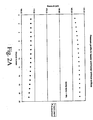
- FIG. 2A An example of the static pressure increase is seen in Figure 2A , where the static pressures in a header or footer calculated for a large M2M Z-manifold system based upon turbulent pipe turning loss and momentum compensation coefficients.
- Channel 1 is the first connecting channel that the header manifold interacts with
- channel 19 is the last connecting channel the footer interacts with.
- the momentum compensation effect in the header drives the static pressure up with increasing channel number (direction of flow), despite frictional losses, while the combined frictional and momentum compensation losses in the footer drive the static pressure down with increasing channel number.
- the resulting pressure profile drives more flow to the higher number channels due to the larger pressure differential driving force with the same connecting channel flow resistance.
- the M2M header momentum compensation coefficient values tend to be on the same order or higher than seen in pipes from Pigford et al ("Flow distribution in piping manifolds", INDUSTRIAL & ENGINEERING CHEMISTRY RESEARCH, v.22, INDUSTRIAL & ENGINEERING CHEMISTRY RESEARCH, pp. 463-471, 1983 ) (values of 0.4-0.7). These M2M header momentum compensation values have experimentally lead to increases in header static pressure, even at inlet Reynolds numbers below 1000.
- the average header Reynolds number is used as a basis of the M2M momentum compensation coefficient because this coefficient is obtained from the experimental change in the static pressure from the beginning of the connecting channel to the exit by subtracting the frictional pressure drop from it, which is based upon the average Reynolds numbers.
- the connecting channel openings can be quite long in the direction of flow in the M2M manifold and spaced close together, the pressure can change appreciably in the manifold, as mentioned in the previous section.
- the Reynolds number in the header can change appreciably in an M2M manifold due to its small hydraulic diameter and large mass flux rates needed to supply fast reactions, high effectiveness heat exchangers and other unit operations aided by microchannel architecture. Some preferred embodiments have operational contact times (contact times through the connecting channels) of fifty milliseconds and less, and some have contact times of ten milliseconds and less.
- the value of the Reynolds numbers in preferred embodiments can vary across the M2M manifold from turbulent flow, to transition flow to laminar flow; in other preferred embodiments it can vary from transition flow to laminar flow. In other preferred embodiments it can vary from transition flow to turbulent flow.
- the friction losses and the M2M momentum compensation losses the latter seen in Figure 2B , change with it. These flow regime changes affect the pressure profiles in the M2M manifold and can contribute to poor flow distribution.
- the turning loss is defined as the static pressure change the connecting channel pays to divert the flow to and from the manifold to the connecting channel.
- the turning loss is a function of
- the header turning loss tends to be higher for the connecting channels closest to the header entrance than to those farther downstream.
- This change in the turning loss with position in the manifold is based upon the change in the manifold head: The head value decreases in the direction of header flow, so diverting a fraction becomes less energy intensive.
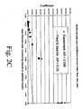
- Figure 2C shows the experimental values of the M2M header manifold turning loss coefficient measured in a microchannel M2M header manifold with an grate interface to manifold area ratio of 0.09, plotted versus the connecting channel to upstream M2M header manifold mass flow rate ratio of the grate interface to the manifold just upstream of the grate interface. Also in Figure 2C are the turning loss coefficients for large dimension manifold from Fried and Idelchik ("Flow resistance: A design guide for engineers," Hemisphere Publishing Corporation. 1989 ) shown in solid line.
- microchannel M2M (macro to micro) turning loss coefficients follow a similar trend to that of the Fried and Idelchik turning loss coefficients: the values increase with decreasing connection to manifold cross-sectional area ratio. This implies that a larger pressure drop is needed to turn manifold flow into a smaller connecting channel opening.
- the turning loss coefficient increases with increasing connecting channel to upstream M2M header manifold mass flow rate ratio (or increase with position down the manifold, 0 being for the first channel, I for the last channel).
- the turning losses based upon the product of the manifold head upstream of the grate interface and the turning loss coefficient, are higher for the first channel in the header than for the last channel if the connection to manifold cross-sectional area ratios are constant.
- microchannel turning losses in Figure 2C are a factor of 2 to 5 higher than turbulent pipe values, making the turning losses even higher than pipes for connecting channel to upstream M2M header manifold mass flow rate ratios greater than 0.2.
- the manifold aspect ratio (largest side of the rectangle over the smallest) of the M2M manifold causes the high header turning losses.
- M2M manifold channel heights are constrained by stacking limitations, as there is often a limited amount of height available between repeating layers. Faced with the restriction of channel height, the M2M manifold can increase its width to increase the overall manifold cross-sectional area for flow. By increasing the manifold cross-sectional area for flow, one can lower both frictional losses and momentum compensation static pressure changes.
- the local manifold head is also decreased.
- the M2M manifold channel aspect ratio increases, the flow turning from the manifold into the connecting channel sees increasing shear stress from the channel walls above and below. These wall shear stresses increase the turning loss pressure drop with increasing M2M manifold aspect ratio, where circular pipes and nearly square cross-sectioned ducts have much less of this.
- the M2M manifold channel aspect ratio for the M2M turning loss coefficient in Figure 2C is roughly 16:1.
- Figure 20 shows the negative values of the experimental M2M footer turning loss coefficients for the footer manifold plotted versus the local connecting channel connecting channel to upstream M2M header manifold mass flow rate ratio of the connecting channel to that of the highest manifold flow rate at the connection, downstream of the footer connection.
- the M2M footer turning loss coefficients in Figure 2D are for a connecting channel interface to manifold area ratio of 0.09 and an M2M manifold aspect ratio of 16:1, and the large manifold numbers from Fried and Idelchik ("Flow resistance: A design guide for engineers," Hemisphere Publishing Corporation, 1989 ) for the same connection to manifold cross-sectional area ratio are plotted.
- the negative value footer turning coefficients for the pipe manifolds show a monotonic increase in the footer turning loss coefficient with increasing connecting channel to upstream M2M header manifold mass flow rate ratio.
- These negative footer turning loss coefficients in Figure 2D for both cases means that these coefficients have a negative value, so when the footer turning loss coefficient is multiplied by the manifold head downstream of the connecting channel there will be a net increase in the static pressure from the connecting channel outlet to the manifold. This static pressure increase compensates for the static pressure header turning loss to some degree.
- the footer turning loss coefficient for the 16:1 M2M manifold aspect ratio is a factor of two or three smaller than that of the Fried and Idelchik footer turning loss coefficients.
- the M2M manifold aspect ratio is probably a strong contributor to the difference in footer turning loss coefficient values, with wall shear stress lowering the net static pressure increase compared to the large manifold system in Fried and Idelchik.
- M2M manifold momentum compensation and M2M manifold turning losses coefficients diverge strongly in value from reported values used for large pipe and duct systems, mostly due to the effect of large M2M manifold aspect ratio manifold channels. These large M2M manifold aspect ratios are needed to slow down the velocities in the M2M manifold, which in turn decrease local head values which drive the friction, turning and momentum effects.
- a wide M2M channel can be split into several smaller manifolds of smaller widths that distribute flow to a fraction of the total connecting microchannels. These smaller manifolds are referred to as sub-manifolds.
- Flow into the M2M of a microdevice is usually routed through a large pipe, tube, or duct. Each large pipe or duct may further serve to connect multiple microdevices operating in parallel. Flow distribution occurs through multiple layers.
- One large pipe or duct meters flow to one or two or more microdevices. Once flow enters the microdevice, it may then be further segregated into submanifolds. Each submanifold serves to distribute flow to at least two or more connecting channels. Flow may then be further divided within a connecting channel into subchannels.
- Subchannels may be formed, for example, by the use of fins (either inserted before or after bonding) or integral (such as those formed from the laminae or shims). Flow in one microchannel may be divided into at least two subchannels and in some embodiments, 10 to 100 subchannels.
- FIG. 3A shows a M2M Z-manifold split into two separate M2M sub-manifolds 312, 314.
- the sub-manifold includes length in addition to the distribution zone of length L M2M . This additional length can be used to tailor the pressure drop for the sub-manifold.
- FIG. 3B shows a sub-manifold design for an L-manifold with two sub-manifolds and connecting channels of equivalent flow resistance.
- the width ofthe sub-manifold with the longer upstream flow path, W 2 is wider than the path for the sub-manifold with the shorter upstream flow path, w 1 .
- This difference in upstream widths allows a means of decreasing the flow resistance for the longer flow path sub-manifold and increasing the flow resistance of the shorter flow path sub-manifold so that both sub-manifolds can meter the same amount of total flow.
- a similar method to this L-manifold's sub-manifold width design can be used for U-manifolds, which have a similar problem matching pressure drops in multiple sub-manifolds with the added burden of matching the total flow resistance between sub-manifold that include headers and footers of differing lengths.
- An additional benefit can be that the walls separating sub-manifolds can act as pillars of mechanical support to handle loads applied the wall shims directly above and below in the direction of stacking.
- FIG. 3C shows an example in which one or more shims whose microchannels end in a bar 37 perpendicular to the channels' axes, signaling the end of the microchannel.
- the bar 37 forms a grate that defines one side of a manifold 370.
- the plane created by the bar 37 and the open space in the adjacent channel is the connecting channel plane exit or entrance.
- This connecting channel plane design is similar to that illustrated by Golbig et al and discussed in Example 1, except the connecting channel in Golbig's stays in the plane under 37 and doesn't extend into the plane of 37.
- each crossbar 39 (upper shim), 38 (lower shim) forms a portion of the grate.
- the opening 36 created by the differences in the shim channel's ends creates an interface for fluid flow between the microchannels 35 and the M2M manifold.
- Figure 3D shows the "grate" concept for a single sub-manifold.
- fluids flows in the M2M and turns into and over the outstretched "grate" 38, entering the interface channel 36 created by the lower shim 38 and the upper shim 39 that marks the end of the microchannel. The flow then leaves the interface and enters the microchannels 35.
- the flow distribution can be tailored by varying the degree the "grate” sticks out into the manifold over the length of a M2M manifold and also by varying the width of the opening 36 under the crossbar 33.
- the design in Fig. 3D has been tested in a flow distribution test device.
- a "gate” connects an M2M manifold to two or more connecting microchannels. Gate features can help distribute flow with a lower pressure drop than a conventional orifice, which seeks to obtain flow distribution by making all the flows pay an equally large sudden expansion and contraction pressure drop.
- the gate uses turning losses to meter flow to a connecting channel, set of connecting channels, or submanifold, and does so by varying the gate cross-sectional area. This tailoring of the turning loss allows the gate to compensate for changes in the manifold pressure profiles so that the connecting channel pressure drops are equivalent. Gates also use friction losses, expansion and other distribution features to add back pressure. By varying gate cross-sectional area it is possible to add back pressure to or remove backpressure from a sub-manifold in a larger manifold cascade as a means of controlling overall sub-manifold flow resistance.
- orifice gates 31 in the connecting channel smooth out distribution by forcing flow through a narrowed opening in the entrance of the connecting channels.
- Figures 3E and 3F show an example of a gate, with an opening in the gray shim to let in flow through the wall created by the stacking of two or more shims.
- This "gate” is an extension of the “grate” design in that it brings an end to the connecting microchannels in shim geometry and allows access to the microchannels from the M2M manifold.
- Gates and grates use the turning losses to equalize the static pressure profiles at the connecting channel interfaces, but the manner in which they do so are different from orifices. Orifices use constant small manifold connection cross-sectional areas to impose large flow resistances for each connection, and incur large operating costs in the form of higher overall pressure drops.
- the inventions described in gates and grates use two or more openings of varying cross-sectional area to use the naturally occurring turning losses to overcome the manifold static pressure profiles caused by manifold physics.
- the gate openings in the direction of flow decrease in size to compensate for the larger turning losses for the first opening and the increased static pressure driving force at the last two gates caused by momentum compensation. These gate sizes help control flow without the large pressure drops associated with orifice flow resistance.
- DPR 2 is greater than two, more preferably greater than 5, in some preferred embodiments it is greater than 10, and in some embodiments 5 to 30. The higher the ratio, the less operational costs incurred by the manifold from pressure drop it gives.
- the regime of flow entering a macromanifold is typically turbulent or transition.
- the flow then undergoes additional regime change in the manifold within the microdevice from turbulent, to transition, to laminar.
- the flow may only undergo one regime change, from turbulent to transition or from transition to laminar.
- the ratio Mo compares the largest M2M manifold head value, the driving force for turning losses and momentum compensation static pressure changes, to the friction losses the manifold would see if the largest M2M manifold head was applied over the entire manifold length L M2M .
- Small values of Mo would indicate that the M2M effects would be small in comparison to the friction losses, negating some of the effectiveness of sub-manifolds and all the effectiveness of grates and gates to control flow distribution. If the Mo value was greater than some small ratio, for example, Mo > 0.05, the head driven turning losses and momentum compensation terms contribute to flow distribution.
- FA number An alternate for the Mo number is the FA number.
- the purpose of FA number is to avoid the laminar creeping flow distributed over short manifold lengths.
- the FA expression is a function of flow rate/flow regime (or Reynolds number), hydraulic diameter of manifold and Length of manifold.
- FA 0.058 + 0.0023 ⁇ ln Re 2 2 ⁇ D L M ⁇ 2 ⁇ M ⁇ 0.01 where hydraulic diameter D in inches, manifold length L M2M in inches and Reynolds number Re have the same definition as that for Mo.
- FA 0.01.
- the hydraulic diameter of sub-manifold is 0.080" (0.20 cm)
- the table below gives the length requirement of a sub-manifold with FA ⁇ 0.01.
- Reynolds number Length of sub-manifold (in) 10 L M2M > 0.04" 100 L M2M > 0.09"
- a microchannel-based module was designed to perform steam-reforming of methane, with heat supplied by combustion of air and fuel.
- the combustion and steam reforming reactions are conducted in the same device, which has three zones:
- the fuel channel is coated with different types of catalyst which promotes combustion at low temperatures (heterogeneous combustion).
- the heat of combustion is transferred through the wall to the reaction channel. This heat drives the steam-reforming reaction.
- a module combustion M2M manifold was designed to achieve equal flow distribution of combustion reaction streams (fuel such as natural gas, hydrogen, carbon monoxide, and the like with or without air to the fuel side, air to the air side) to the array of combustion channels so that they would mix inside the connecting microchannels within the module.
- the air and fuel enter from opposite sides of the module, mix within the combustion section, and the combined exhaust makes a u-tum before traveling down the return microchannel and leaves the end of the module, forming header L-manifolds for both streams.
- the total combined M2M and channel pressure drop was important, and achieving a good distribution of air and fuel in each channel was especially important due to the need to mix near stoichiometric mixtures of fuel and oxidant (air).
- the means of achieving equal flow distribution for this system was complicated by a number of fabrication and macro manifold constraints.
- the resulting design included innovations such as: multiple (six, in the illustrated example) sub-manifolds with multiple (12) channels per sub-manifold; and multiple (3) gates per sub-manifold with multiple (4) downstream connecting channels per gate.
- Fig. 4A is an exploded view of shims in the stacked device.
- Figs. 4-22 are overhead views of shims that were assembled into the device.
- the overall size of all the shims is 31.47" (length) X 22.00" (width).
- the shim length and width are as defined in Figure 4B .
- the thickness of the shim is defined in the direction perpendicular to length and width. Shims from 1-28 were stacked on top of each other to form a repeating unit of the device.
- the stack height of the repeating unit is 0.43". There are total 49 repeating units in the device.
- the overall height of the device is 23.1".
- a perimeter margin of 1.00" along the length and 1.50" along the width has been marked. This marked perimeter metal does not become the part of final device and was provided only to enhance metal diffusion bonding.
- rectangular slots are made. The purpose of these slots is to provide a location indicator for opening sub-manifolds during post-bonding fabrication operations, such as plunge electrodischarge machining.
- the slots on the right side are for fuel stream 12 and reactant stream 14 sub-manifolds, the slots on the left side are for air stream 16 and product stream 18 and the slots at the bottom 19 are for exhaust stream.
- All the openings in the shims are through slots or holes. Passages for the flow in the device are through slots or holes. The flow between the passages is separated either by ribs (within a shim for the same stream) or wall shims (between different streams)
- Figure 4B shows a wall shim.
- the thickness of the shim is 0.020". This shim separates the reforming reaction stream from the fuel stream. The shim also transfers heat generated in combustion channels to the reaction channels for the steam reforming reaction.
- Figure 5 shows a wall shim.
- the thickness of the shim is 0.020". This shim separates the reactant stream from fuel stream.
- the shim also transfers heat generated in combustion channels to the reactant channels for steam reforming reaction.
- the slots 32 in the shims are to hold catalyst support fins in the fuel channel.
- Figure 6 shows a shim that forms the passage for fuel stream.
- the thickness of the shim is 0.012".
- the slots on the shims form features for the fuel stream.
- the fuel enters from the right end of the shim through 6 inlets 44 (referred as sub-manifolds).
- the widths of these sub-manifolds perpendicular to the direction of flow, starting from the bottom are 0.60", 0.60", 0.55", 0.50", 0.50" and 0.40". All six sub-manifolds are separated by 0.060" rib.
- the lengths of the sub-manifolds in the flow direction, starting from the bottom are 16.93", 14.11", 11.29", 8.47", 5.65", and 2.83".
- each sub-manifold distributed into three super-channels as shown in the drawing.
- the flow goes over a 0.060" rib to enter the super-channel from sub-manifolds.
- the length of super-channels in the direction of flow is 0.50".
- Each super-channel further divides the flow into four channels.
- the numerous thin channels 42 are separated by 0.060" ribs except for every 4th rib which is 0.120". All the channels 42 are 0.160" wide.
- the flow passes through the heat exchanger zone 46, receiving heat from exhaust and product stream and enters combustion zone 48. In the combustion zone, fuel mixes with air and combusts in the presence of combustion catalyst.
- Figure 7 shows another shim that forms the passage for fuel stream in conjunction with the shim shown in Figure 6 .
- the thickness of this shim is 0.025".
- the slots on the shims form features for fuel stream.
- the fuel enters from the right end of the shim through 6 inlets 52 (referred as sub-manifolds).
- the widths of these sub-manifolds perpendicular to the direction of flow, starting from the bottom are 0.60", 0.60", 0.55", 0.50", 0.50" and 0.40". All six sub-manifolds are separated by 0.060" ribs 54.
- the lengths of the sub-manifolds in the flow direction, starting from the bottom are 16.93", 14.11 ", 11.29", 8.47", 5.65'', and 2.83".
- the sub-manifolds have small openings 56 (gates) to meter the flow into the channels.
- Each sub-manifold has 3 gates. There are a total of 18 gates to meter the flow into the channels.
- the length of the gates in the flow direction is 0.060".
- the widths of the gates starting from the right are- 0.105", 0.102", 0.094", 0.122", 0.199", 0.103",0.143", 0.142", 0.127", 0.160", 0.161", 0.145", 0.299", 0.230", 0.152", 0.560", 0.555", and 0.550".
- the channels 58 are separated by 0.060" ribs except for every 4th rib which is 0.120". All the channels are 0.160" wide.
- the flow passes through the heat exchanger zone 57, receiving heat from exhaust and product stream and enters combustion zone 59. In the combustion zone, fuel mixes with air and combusts in the presence of combustion catalyst.
- Figure 8 illustrates a jet shim that acts as a wall shim between fuel and air stream in the manifold and heat exchanger zone.
- the thickness of this shim is 0.010".
- this shim provides passages 62 (referred as orifices) to mix air into fuel.
- passages 62 referred as orifices
- the first orifice is rectangular slots with semi-circular ends of diameter 0.012". The longest length of the slot is in the direction of flow.
- the second orifice is equilateral triangular in shape with 0.012" side length and is placed at a distance of 0.133" from first orifice.
- the third & fourth orifices are of 0.012" diameter holes placed 0.267" from the first orifice.
- the fifth orifice is again a same triangular slot placed 0.386" from the first orifice.
- Orifice six to fifteen are circular holes with diameter 0.012" and are placed at 0.594", 0.769", 0.969", 1.168", 1.615", 2.112", 2.658", 3.257", 3.257”, 3.857", 4.624" from the first orifice.
- Orifice sixteen and seventeen are 0.012" diameter holes place 5.392" from first orifice.
- a continuous 0.050" slot 64 is made on the top of the shim to transport combusted fuel (exhaust) over to exhaust channel. This slot allows flow to travel between connecting channels in between the header and the footer.
- Figure 9 shows the shim that forms the passage for the air stream.
- the thickness of the shim is 0.012".
- the slots on the shims form features for air stream.
- the air enters from the left end of the shim through 6 inlets 92 (referred as sub-manifolds).
- the widths of these sub-manifolds perpendicular to the direction of flow, starting from the bottom are 0.60", 0.60", 0.55", 0.50", 0.50" and 0.40". All six sub-manifolds are separated by a 0.060" rib.
- the lengths of the sub-manifolds in the flow direction, starting from the bottom are 16.93", 14.11 ", 11.29", 8.47", 5.65", and 2.83".
- each sub-manifold distributes into three super-channels 94 as shown in the drawing.
- the flow goes over 0.060" rib 96 to enter the super-channel from sub-manifolds.
- the length of super-channels in the direction of flow is 0.50".
- Each super-channel further divides the flow into four channels. These channels are separated by 0.060" ribs except for every 4th rib which is 0.120". All the channels 99 are 0.160" wide.
- the flow passes through the heat exchanger zone, receiving heat from exhaust and product stream and enters the combustion zone. In the combustion zone, air flows into the F1 ( Fig. 4 ) and F2 shim ( Fig. 5 ) through orifices 62 to combust the fuel.
- a continuous 0.050" tall slot 95 is made on the top of the shim to transport combusted fuel (exhaust) over to the exhaust channel.
- Figure 10 shows another shim that forms the passage for the air stream in conjunction with the shim shown in Figure 9 .
- the thickness of the shim is 0.025".
- the slots on the shims form features for the air stream.
- the air enters from the left end of the shirt through 6 inlets (referred as sub-manifolds).
- the widths of these sub-manifolds perpendicular to the direction of flow, starting from the bottom are 0.60", 0.60", 0.55", 0.50", 0.50" and 0.40". All six sub-manifolds are separated by a 0.060" rib.
- the lengths of the sub-manifolds in the flow direction, starting from the bottom are 16.93", 14.11", 11.29", 8.47", 5.65", and 2.83".
- the sub-manifolds have small openings (gates) to meter the flow into the channels.
- Each sub-manifold has 3 gates 104. There are total 18 gates to meter the flow into the channels.
- the length of the gates in the flow direction is 0.060".
- the widths of the gates starting from the right are -0.188", 0.175", 0.172", 0.165", 0.167", 0.167", 0.240", 0.235", 0.232", 0.260", 0.260", 0.260", 0.260", 0.277", 0.277”, 0.277", 0.590", 0.580", and 0.588".
- the channels are separated by 0.060" ribs except for every 4th rib which is 0.120". All the channels are 0.160" wide.
- the flow passes through the heat exchanger zone, receiving heat from exhaust and product stream and enters the combustion zone.
- air flows through the jet shim to react with the fuel in the fuel channels.
- Figure 11 shows a wall shim that separates the air stream from the exhaust stream.
- the thickness of the shim is 0.010".
- Figure 12 shows a shim with exhaust stream channels.
- the thickness of the shim is 0.020".
- the exhaust stream flows from top of the shim to the bottom of the shim. All the passages for the flow are 0.160" wide and are separated by 0.060" ribs except for every 4th rib which is 0.0120".
- the exhaust enters a passage from a U-tum at the top of the shim, passes through the heat exchanger zone exchanging heat with fuel and air and flows out at the bottom of the shim.
- Figure 13 shows a shim with exhaust stream channels that pair with the channels in the shim shown in Fig. 12 .
- the thickness of the shim is 0.020".
- the exhaust stream flows from top of the shim to the bottom of the shim. All the passages for the flow are 0.160" wide and are separated by 0.060" ribs except for every 4th rib which is 0.0120".
- the exhaust enters at the top of the shim in the reactor zone, passes through the heat exchanger zone exchanging heat with fuel and air and flow out at the bottom of the shim.
- a rib 132 of 0.060" serves as support for bonding.
- Another shim identical to the shim in Fig. 12 is stacked over the shim in Fig. 13 .
- Another shim identical to the shim in Fig. 11 is next in the shim stack.
- Another shim identical to that shown in Fig. 10 is next in the shim stack.
- Another shim identical to that shown in Fig. 10 is next in the shim stack.
- Another shim identical to that shown in Fig. 10 is next in the shim stack.
- Another shim identical to that shown in Fig. 10 is followeded by another shim identical to that shown in Fig. 9 .
- Another shim identical to that shown in Fig. 8 followed by another shim identical to that shown in Fig. 7 .
- Another shim identical to that shown in Fig. 6 followsed by another shim identical to that shown in Fig. 5 .
- another shim identical to that shown in Fig. 4B is next in the shim stack.
- Another shim identical to that shown in Fig. 10 is next in the shim stack.
- Figure 1 shows the shim that forms the passage for reactant stream.
- the thickness of the shim is 0.010".
- the slots in the shim form passages for the flow of reactant stream.
- the reactant enters from the right end of the shim through 6 inlets 142 (referred as sub-manifolds).
- the widths of these sub-manifolds perpendicular to the direction of flow are 0.539". All six sub-manifolds are separated by 0.060" rib.
- the lengths of the sub-manifolds in the flow direction, starting from the bottom are 16.93", 14.11", 11.29", 8.47", 5.65", and 2.83".
- the sub-manifolds have small openings 144 (gates) to meter the flow into the channels.
- Each sub-manifold has 3 gates. There are a total 18 gates to meter the flow into the channels.
- the length of the gates in the flow direction is 0.060".
- the widths of the gates starting from the right are - 0.229", 0.209", 0.173", 0.229", 0.209", 0.173", 0.229", 0.209", 0.173", 0.229", 0.209", 0.173", 0.229", 0.209”, 0.173", 0.229", 0.209”, and 0.173".
- the channels are separated by 0.060" ribs except for every 4th rib which is 0.120". All the channels are 0.160" wide.
- the length of the flow passage in the shim from the respective sub-manifold is 0.70".
- slots 146 (7.00" long and 0.82"wide) are made. The purpose of these slots is to hold the fins which provide surface area for steam-reforming reaction.
- Figure 15 shows another shim that forms the passage for reactant stream in conjunction with the shim shown in Figure 15 .
- the thickness of the shim is 0.012".
- the reactant enters from the right end of the shim through 6 inlets 152 (referred as sub-manifolds).
- the widths of these sub-manifolds perpendicular to the direction of flow are 0.539". All six sub-manifolds are separated by 0.060" rib.
- the lengths of the sub-manifolds in the flow direction, starting from the bottom are 16.93", 14.11", 11.29", 8.47", 5.65", and 2.83".
- the flow from each sub-manifold distributed into three super-channels as shown in the drawing.
- the flow goes over a 0.060" rib 154 to enter the super-channel 156 from sub-manifolds.
- the length of super-channels in the direction of flow is 0.539".
- Each super-channel further divides the flow into four channels 158. Channels are separated by 0.060" ribs except for every 4th rib which is 0.120". All the channels are 0.160" wide.
- the flow passes through the heat exchanger zone, receiving heat from product and exhaust stream and enters the reactor zone. In the reactor zone, the steam reforming reaction occurs in the presence of combustion heat
- Figure 16 shows a wall shim that separates the reactant stream from the product stream.
- the thickness of the shim is 0.010".
- a continuous 0.050" slot 162 is made on the top of the shim to transport products formed in the reactant channel over to the product channel.
- Figure 17 shows the wall shim and separates the reactant stream from the product stream.
- the thickness of the shim is 0.010".
- a continuous 0.21" tall slot 172 is made on the top of the shim serves to transport products formed in the reactant channel over to the product channel.
- Figure 18 shows a shim for product flow.
- the thickness of the shim is 0.018".
- the product flows in the passages from the top of the shim to the bottom of the shim. Passages are 0.160" wide and are separated by 0.060" rib except for every 4 th rib which is 0.120" wide.
- the flow from the passages is then collected in another set of passages 184 (referred as sub-manifold) that run perpendicular to first set of passages.
- These passages are separated from first set of passages by 0.060" ribs that in conjunction with shims in Figure 17 and Figure 19 form "grates".
- the width of each sub-manifold in the direction perpendicular to flow direction is 0.539".
- the lengths of sub-manifolds in the flow direction starting from bottom sub-manifold are 16.93", 14.11", 11.29", 8.47", 5.65", and 2.83".
- Figure 19 shows a wall shim that separates reactant stream from product stream.
- the thickness of the shim is 0.010".
- a continuous 0.21" tall slot 192 is made on the top of the shim to transport products formed in the reactant channel over to the product channel.
- Figure 20 shows a wall shim and separates reactant stream from product stream.
- the thickness of the shim is 0.010".
- a continuous 0.050" tall slot 202 is made on the top of the shim to transport products formed in the reactant channel over to the product channel.
- Figure 21 shows the shim that forms the passage for reactant stream.
- the thickness of the shim is 0.012".
- the reactant enters from the right end of the shim through 6 inlets 212 (referred as sub-manifolds).
- the widths of these sub-manifolds perpendicular to the direction of flow are 0.539".
- All six sub-manifolds are separated by 0.060" ribs 214.
- the lengths of the sub-manifolds in the flow direction, starting from the bottom are 16.93", 14.11", 11.29", 8.47", 5.65", and 2.83".
- the flow from each sub-manifold distributed into three super-channels 216 as shown in the drawing.
- the flow goes over a 0.060" rib 218 to enter the super-channel from sub-manifolds.
- the length of super-channels in the direction of flow is 0.539".
- Each super-channel further divides the flow into four channels 219. Channels are separated by 0.060" ribs except for every 4th rib which is 0.120". All the channels are 0.160" wide.
- the flow passes through the heat exchanger zone, receiving heat from product and exhaust stream and enters the reactor zone. In the reactor zone, the steam reforming reaction occurs in the presence of combustion heat.
- Figure 22 shows a drawing of a shim that in conjunction with shim in Figure 21 forms the flow channels for reactant stream.
- the slots in the shim form passages for the flow of reactant stream.
- the reactant enters from the right end of the shim through 6 inlets (referred as sub-manifolds).
- the widths of these sub-manifolds perpendicular to the direction of flow are 0.539". All six sub-manifolds are separated by 0.060" rib.
- the lengths of the sub-manifolds in the flow direction, starting from the bottom are 16.93", 14.11", 11.29", 8.47", 5.65", and 2.83".
- the sub-manifolds have small openings (referred as orifices) to meter the flow into the channels.
- Each sub-manifold has 3 orifices. There are total 18 orifices to meter the flow into the channels.
- the length of the flow opening in the flow direction is 0.060".
- the widths of the openings starting from the right are - 0.229", 0.209", 0.173", 0.229", 0.209", 0.173", 0.229", 0.209", 0.173", 0.229", 0.209", 0.173", 0.229", 0.209”, 0.173", 0.229", 0.209”, and 0.173".
- the channels are separated by 0.060" ribs except for every 4th rib which is 0.120". All the channels are 0.160" wide.
- the length of the flow passage in the shim from the respective sub-manifold is 0.70". In the reactor zone, slots (7.00" long and 0.82"wide) are made. The purpose of these slots is to hold the fins which provide surface area for steam-reforming reaction.
- Cross-sectional area restrictions in gates and grates, preferably at the front of connecting channels can be formed, for example, by: holes through walls, bumps from a lower surface, wall projections, and combinations of these.
- Features such as rounded bumps can be formed by etching.
- Manifold walls can be rounded (such as to appear like a race track). Flow into a manifold can enter from above or below; and, in many preferred embodiments, in-plane, such as from a side header attached to the side of a laminated shim stack. Manifold walls can be solid or with gaps.
- a manifold in the illustrated case, a footer
- a footer can be used to separate two phases of differing density in a microchannel device by gravity and/or centrifugal forces.
- Walls between connecting channels may be the same or different lengths. Gates to groups of channels can be centered or offset from the center of the gate's connecting channels.
- Fig. 24 illustrates a manifold structure with an offset gate and channels of differing lengths. In the illustrated manifold, flow momentum (of a stream entering from the side of the connecting channels) for a centered gate would tend to force the greatest flow through downstream channel 242 on the far right side due to the incoming stream coming from left to right; however, the gate 244 positioned in the downstream portion of the manifold (in the illustrated embodiment, the gate is attached to the downstream manifold wall 246) blocks a portion of the flow.
- At least one internal channel wall in the downstream section 249 of a connecting channel set is longer than a channel wall in the upstream section. More preferably, at least two (or at least 4) internal channel walls in the downstream section 249 of a connecting channel set are longer than a channel wall in the upstream section. Still more preferably, the downstream section 249 of a connecting channel set contains at least two internal channel walls 243, 248 that project progressively further into a manifold zone 245.
- the downstream section 249 of a connecting channel set longer than a channel wall in the upstream section there are a combination of an offset and at least one internal channel wall in the downstream section 249 of a connecting channel set longer than a channel wall in the upstream section, since this combination can provide more equal flow distribution (smaller Q 1 or Q 2 ) for large flow rates than either feature individually.
- "longer” means projecting the channel further into a manifold zone 245.
- a similar design concept can also be used for the footer.
- the stream from the connecting channel farthest from the footer manifold's outlet will have a larger momentum vector in the manifold's flow direction than those connecting channel closer to the manifold's exit. This will lower the flow resistance for the farthest away channel for leaving the manifold connection, so to balance the flow leaving the channels we can then vary the geometry around the channel as described above for 242.
- Fig. 25a illustrates flow straightening in a multiple gate configuration. Flow enters from the side and is momentum biased toward flow through the downstream portion of the connecting channels. Gates 256, 258 can be used to equalize flow between channel sets 257, 259. Flow through connecting channels 254 can be equalized by extending the length of a manifold zone a distance L 2 (or, in the case of Fig. 25a , a submanifold zone 252).
- the zone has a length L 2 of at least three times longer than the manifold length L M2M (see Figure 1A ) in the flow direction, in some embodiments at least 6 times longer than the manifold length L M2M , in some embodiments, to save space L 2 is 20 times or less longer than the manifold length L M2M .
- L 2 is 20 times or less longer than the manifold length L M2M .
- Fig. 25b shows a manifold with a straightening zone 2502 and a flow bump (a grate) 2504 before the entrance of the connecting channels 2506.
- Entering stream 2505 may come from a side manifold in which flow emanates from above, below, or in the plane.
- Fig. 25c is an exploded view of sheets that can be used to form the manifold/channel structure.
- Figs. 26a and 26b illustrate a manifold 262 with straight connecting channels 264.
- the connecting channels are partially blocked by flow bumps 266.
- the flow enters the connecting channels from the manifold, but can redistribute amongst channels through the cross- connecting channels underneath the connecting channels.
- Two such cross-connecting channels are shown in Figure 25a , made by the layer 266.
- the advantage for such a system is that cross-connecting channels in 266 can allow for redistribution of flow should manifold design not allow for acceptable distribution due to space constraints.
- a modified version of the structure of Fig. 26 could be microchannel apparatus, comprising: an array of parallel microchannels disposed in a plane; wherein the array of parallel microchannels are connected at one end by an inlet manifold and at their opposite end by an outlet manifold; and at least one channel disposed above or below the array of parallel microchannels and disposed at an angle of at least 20 degrees (preferably substantially 90 degrees) relative to the parallel microchannels and disposed between the inlet manifold and outlet manifold and connected via openings to the parallel microchannels in the array.
- Such a structure could be obtained by forming connections through the walls 265, 267 of second channel 261. The connections through the walls 265, 267 would connect to an inlet and outlet respectively so that there could be cross flow through the second channel.
- a plate can separate the first and second layers except for an aperture or apertures through the plate to provide communication between the first layer and the second channel.
- Such a construction could be used, for example, to mix components or as a pathway to add a coating material from one layer to the next.
- Fig. 27 is an exploded view (also a preassembled view) of an alternative design having flow bumps 272, 274 in an alternating arrangement such that there is no straight flow path through the connecting channels. This structure creates extensive interchannel mixing.
- Fig. 28 illustrates a manifold with cross-current flows 282, 284 that mix over the length of the manifold zone 286 via gaps 285 in dividing wall 287.
- This cross-flow mixing reduces momentum biased flow into the connecting channels.
- the mixing can be a single component, two or more reactants, or two phases.
- the in-flows are coplanar; however, it should be appreciated that mixing could alternatively or additionally be accomplished through holes in the sheet above or below the manifold.
- a manifold can be inclined to change the cross-sectional area of the manifold in the direction of flow, which changes the local connecting channel interface to manifold area ratio and the channel M2M manifold aspect ratio.
- inclined is meant that the height (not merely the width) of the manifold varies.
- the manifold slopes upward so that the smallest volume is adjacent to the connecting channel furthest downstream (i.e., the opposite of the slope in Fig. 29 ). This structure can be made by etching.
- the gates from the manifold to the connecting channels can be angled. This is schematically illustrated in Fig. 30 .
- An angled opening can be made by etching.
- the angled flows can add or subtract from turning loss resistance and can be designed to make flow more equal through the connecting channels.
- angled means that the gate is sloped such that the center line through the gate forms an angle between 2 and 98 degrees or between 92 and 178 degrees, more preferably between 20 and 80 or between 100 and 170 degrees with respect to the center line through the connecting channels.
- the design is as illustrated where at least one channel (or preferably more) that is in the upstream section of the manifold is angled to reduce turning loss (with flow) while at least one channel (or preferably more) that is in the downstream section of the manifold is angled to increase turning loss (against flow).
- Fig. 31 illustrates an exploded (or preassembly) view of stacked connecting channels that include an offset region 312 that allows interchannel mixing.
- a channel wall or walls in a first layer extend to provide a fluid pathway into a second adjacent layer.
- baffles are placed within the headers (not shown).
- Fig. 32 illustrates an alternative form of gate in which porous bodies are placed between a manifold 322 and connecting channels.
- the porous bodies are arranged such that the greatest resistance to flow is present in the porous body 324 furthest downstream relative to the manifold while the relatively less resistance to flow is present in upstream porous body 326 for a header manifold with a Mo value greater than 0.05. This puts the highest flow resistance for the zone with the highest static pressure value in the manifold, a product of increasing static pressure from momentum compensation.
- a header for a U-manifold with a Mo value greater than 0.05 may want the order reversed from that described for the Z-manifold and L-manifold headers to compensate for momentum compensation and friction losses in the footer. More generally, it is preferred that a porous body with a relatively greater resistance to flow is located downstream in the header manifold relative to a porous body with a relatively lesser resistance to flow for a header manifold for a Z-manifold or L-manifold. The reverse is true for the U-manifold. For flow distribution through connecting channels of equal width, at least 3 porous bodies increase in flow resistance with increasing distance downstream in the manifold.
- the porous bodies can be catalytic (e.g. in a reactor) or noncatalytic.
- a foam is a preferred example of a porous body.
- Fig. 33 illustrates an embodiment in which flow is affected by a flexible projection 332 through a channel wall.
- the flexible projection can project from one side of a wall or through a channel wall and into both adjacent channels.
- microdevices 3402, 3404 each with an internal micro-to-macro manifold may be further connected together with a macromanifold 3405 (see Fig. 34A ) to achieve any desired capacity or productivity.
- This level of manifolding may comprise pipes or ducts that connect streams between microdevices. At least one stream can be in a single pipe 3406 or duct with an inlet 3407 or outlet 3408 to each parallel microdevice. In some embodiments, all streams are connected with a unique pipe or duct. In one embodiment, one or more outlet streams 3409 vents to the atmosphere, such as the case of a combustion exhaust stream.
- the pipes or ducts that connect multiple microdevices preferably maintain a hermetic seal around the respective inlet or outlet of a fluid stream for each microdevice.
- the hermetic seal may be achieved by welding or gasket connections.
- the connecting macromanifold pipes or ducts may be connected to each other but in a gas-tight manner to prevent cross-stream leaks or connections.
- an inner pipe that contains the inlet for one stream may contain an outer pipe that is attached to the inner pipe around a portion of the circumference ofthe inner pipe (not shown). Multiple pipes or ducts may be connected in this manner.
- An advantage of this approach includes a reduced amount of metal weight for the macromanifold, control of the thermal profile along the pipes to reduce stress imposed material thickness limits, and reduced total volume required for the macromanifold system.
- the macromanifold represents the first level of flow distribution. Flow enters from a single source and is distributed to two or more microdevices. After flow enters each microdevice it is further optionally segregated into multiple submanifolds. From each submanifold, flow may be further distributed to multiple connecting channels. Finally, an optional embodiment includes a further level of flow distribution to multiple subchannels within each microchannel. Each subchannel may take the form of a fin (either inserted or formed integrally to the device) or other flow distributor housed within a microchannel. There may be three, four, or more levels of flow distribution required for the operation of microdevices that produce a quality index factor of less than 30%, or any of the preferred Q values discussed herein.
- the less significant turning losses for the high aspect ratio channel is due to the cross-sections of large ducts that have square perimeters or have pipe or half-pipe perimeters.
- the turning losses for these cases have less wall shear stress than seen for the high aspect ratio rectangular channels.
- the next two concepts describe means of improving flow distribution to two dimensional channel arrays.
- a single inlet tangent to the direction of flow can result in a stream that distributes the bulk of the flow to the channels opposite to the inlet and could induce large recirculation zones in the header and footer, recirculation from the header to the footer and recirculation or stagnant zones in the device.
- FIG. 34B is a top-down view inside a channel in a device having multiple inlets 3406 parallel to the direction of flow.
- inlet flow is introduced from both sides of a sub-manifold 3402. If flow is introduced from only one side, the bulk of the flow would leave via the header inlet farthest from the main inlet.
- Fig. 34B Also illustrated in Fig. 34B are optional flow directors 3404 that can direct flow through a chamber.
- These flow directors can be louvers (or paddles) that can be collectively or individually rotated to direct flow in a desired direction.
- a louver system was designed where all of the louvers are attached together by an adjoining rod, which will allow all of the louvers to move and rotate at the same time, same direction and to the same position.
- the use of louvers provides a convenient way of changing flow directions within a device. The louvers are able to shift the flow such that it can be biased to the left, middle and right.
- the flow directors are rotatable louvers.
- a heat exchange fluid is passed through the chamber with the heat exchange fluid biased.
- a reaction chamber Stacked adjacent to the illustrated heat exchange chamber, either above and/or below, is a reaction chamber (not shown) in which reactants pass in a cross-flow relationship relative to the heat exchange fluid. This orientation is advantageous if the reaction rate is greatest at the front or back of the reaction chamber and this high-reacting-rate portion is matched to the biased flow through the heat exchanger such that the highest flow of heat exchange fluid is directly adjacent to the highest reaction rate in the adjacent reaction chamber.
- a flow distribution plate prior to a multichannel array. This concept is illustrated in Fig. 35 which shows flow being forced to the periphery of a distribution plate 3502. Generally, this can be accomplished by a plate with orifices preferentially distributed nearer the periphery of the plate than to the center. Preferably, a second orifice plate 3504 with a two-dimensional array of equally distributed holes follows the first plate.
- the combination ofthe first and second plates preferably in further combination with an open redistribution zone (not shown) following the first plate, equalizes pressure over the front surface of an array and reduces flow maldistribution through a multichannel array.
- a partially exploded view of a multichannel device using the combination of first and second flow redistribution plates 3602, 3604 is shown in Fig. 36 .
- FIG. 37 Cross sectional and side views of another design with first and second flow distribution plates is illustrated in Fig. 37 .
- the first orifice plate 3702 has differing gate sizes to control flow.
- the varying gate sizes can either be used to equalize flow, or to provide a nonuniform flow for instances in which nonuniform flow is desired.
- a second orifice plate 3704 with a number of large orifices offset from the orifice position of the first plate (i.e., nonaligned) is needed to divert the flow stream from the single orifice and ensure a uniform distribution within the segment of microchannels (i.e., connecting channel matrix 3706).
- equal flow can be obtained with a portion 2710 of the connecting channel matrix in direct contact with the manifold 3708 without intervening orifice plates.
- plates containing one or more orifice are disposed within the header. See Fig. 38 .
- plates 3802 with one or more orifices are of a shape that fits in the header cross section and can be mounted (sealed or welded) inside the header so as to separate the header of a microchannel device into several segments.
- the orifice sizes are designed according to the desired flow rate and pressure drop for the corresponding group (arrays) of the microchannels to realize a designed stepwise profile of flow rate and pressure drop over the whole device. As the pressure varies from segment to segment, the segment-averaged flow rate in the microchannels can be different from segment to segment or can also be the same for a uniform flow distribution.
- the illustrated design contains 6 microchannels within each segment; however, it should be realized that any number of channels may be present in a segment, for example, in some preferred embodiments, 2 to 100 channels, and in some embodiments 10 to 50 channels.
- the illustrated design has orifice plates with decreasing orifice sizes in the direction of flow to compensate for momentum and provide more equal flow through the connecting channels.
- the illustrated plates are parallel to the connecting channels.
- Orifice plates can have equally distributed orifices of similar or identical sizes, monotonically increasing or decreasing open areas, or can be designed with any desired orifice distribution.
- Fig. 39A shows orifice plates with holes or slots that increase to a maximum area then decrease down their length.
- a moveable orifice plate between a manifold and connecting channels can be used to vary flow rate into connecting channels.
- the plates in Fig. 39B have optional screw holes 392 for use as moveable plates.
- the orifice plate can be moved up or down to vary flow. The plate can be mounted and sealed between the header of the device and the channel inlet face using screws.
- the relative position between the plate and the channels can be changed by unscrewing the plate and moving the plate to a position corresponding to the designed new distribution profile.
- Sheets and strips for forming laminated devices can be formed by processes including: conventional machining, wire EDM, plunge EDM, laser cutting, molding, coining, water jet, stamping, etching (for example, chemical, photochemical and plasma etch) and combinations thereof. For low cost, stamping to cut apertures through a sheet or strip is especially desirable. Any shaping or forming process can be combined with additional steps. Some of the inventive methods can also be characterized by the absence of certain forming techniques; for example, some preferred methods do not utilize etching, casting, melting a powder, molding, chemical or physical deposition, etc.
- a sheet or strip is stacked on a substrate.
- a substrate is broadly defined to include another sheet or strip or a thicker component that could be, for example, a previously bonded sheet stack.
- multiple sheets and/or strips are aligned in a stack before bonding.
- a brazing compound is placed on one or more surfaces of a sheet or strip (or plural sheets and/or strips) to assist bonding.
- Sheets and strips should be aligned in a stack. Alignment can be achieved by making sheets and/or strips with alignment apertures and then using alignment pins to align the sheets and/or strips in a stack. A stack (including a subassembly that does not include all the components of a final device) can be lifted from pins, or the pins can be removed (such as by burning or by pulling out pins), or the pins can become bonded in the stack.
- Another alignment technique utilizes molds for aligning sheets and/or strips; this technique can be especially useful for positioning flow modifiers such as ribs. In some embodiments, molds remain in place while the stack components are attached in place such as by welding, heating an adhesive, or diffusion bonding; subsequently, the molds are removed. In other embodiments, the mold can be removed before the components are bonded. Molds can be reusable or can be single use components that could be removed, for example, by burning out.
- the sheets, strips and subassemblies may be joined together by diffusion bonding methods such as ram pressing or hot isostatic pressing (HIPing). They may also be joined together by reactive metal bonding, brazing, or other methods that create a face seal. Welding techniques, such as TIG welding, laser welding, or resistance welding, may also be used. Devices can alternatively be joined by the use of adhesives.
- diffusion bonding methods such as ram pressing or hot isostatic pressing (HIPing). They may also be joined together by reactive metal bonding, brazing, or other methods that create a face seal.
- Welding techniques such as TIG welding, laser welding, or resistance welding, may also be used.
- Devices can alternatively be joined by the use of adhesives.
- seam welding can be employed to form a complete seal between a substrate, strip and/or flow modifier.
- Tack or spot welding can be used to hold strips, flow modifiers or subassemblies in place, without creating a complete seal along an entire edge.
- the tack welded assemblies will be subjected to a subsequent bonding step.
- Brazing techniques and compositions are known and can be employed in forming devices of the present invention. Braze cycles longer than about 10 hours can result in better devices that show less distortion and have better bonding.
- Techniques for assembly and/or bonding of devices can use the same techniques or a mixture of techniques. For example, a subassembly could be welded together and then welded to a second subassembly that itself was formed by welding. Alternatively, for example, a subassembly could be spot welded together, brazed to a second subassembly, and the combined assembly diffusion bonded.
- microchannel, laminated devices can be made with the components described herein and/or structures described herein and/or made using the methods described herein.
- Such laminated devices can be, for example, heat exchangers, reactors (integrated combustion reactors are one preferred type of reactor), separators, mixers, combinations of these, and other microchannel, laminated devices that are capable of performing a unit operation.
- laminated articles encompasses laminated devices as well as laminated subassemblies.
- the inventive articles contain at least 5 laminae, more preferably at least 10, and in some embodiments, more than 50. In some preferred embodiments, the articles contain at least 2, in some embodiments at least 5 repeating units (with each repeating unit containing at least 3 different laminae).
- At least one fluid is flowing through the manifold, and in some embodiments, this fluid is a gas.
- the header or footer can be shaped to fit an end of a subassembly, for example a square end on a header/footer to match one side of a cubic subassembly.
- the articles may be made of materials such as plastic, metal, ceramic, glass and composites, or combinations, depending on the desired characteristics.
- the articles described herein are constructed from hard materials such as a ceramic, an iron based alloy such as steel, or monel, or high temperature nickel based superalloys such as Inconel 625, Inconel 617 or Haynes alloy 230.
- the apparatuses are comprised of a material that is durable and has good thermal conductivity.
- the apparatuses can be constructed from other materials such as plastic, glass and composites. Materials such as brazes, adhesives and catalysts are utilized in some embodiments of the invention.
- the present invention may include chemical reactions that are conducted in any ofthe apparatus or methods of conducting reactions that are described herein. As is known, the small dimensions can result in superior efficiencies due to short heat and mass transfer distances. Reactions can be uncatalyzed or catalyzed with a homogenous or heterogeneous catalyst. Heterogeneous catalysts can be powders, coatings on chamber walls, or inserts (solid inserts like foils, fins, or porous inserts). Catalysts suitable for catalyzing a selected reaction are known in the art and catalysts specifically designed for microchannel reactors have been recently developed.
- catalysts can be a porous catalyst
- the "porous catalyst" described herein refers to a porous material having a pore volume of 5 to 98%, more preferably 30 to 95% ofthe total porous material's volume.
- the porous material can itself be a catalyst, but more preferably the porous material comprises a metal, ceramic or composite support having a layer or layers of a catalyst material or materials deposited thereon.
- the porosity can be geometrically regular as in a honeycomb or parallel pore structure, or porosity may be geometrically tortuous or random.
- the support of the porous material is a foam metal, foam ceramic, metal felt (i.e., matted, nonwoven fibers), or metal screen.
- the porous structures could be oriented in either a flow-by or flow-through orientation.
- the catalyst could also take the form of a metal gauze that is parallel to the direction of flow in a flow-by catalyst configuration.
- a catalyst support could be formed from a dense metal shim, fin or foil.
- a porous layer can be coated or grown on the dense metal to provide sufficient active surface sites for reaction.
- An active catalyst metal or metal oxide could then be washcoated either sequentially or concurrently to form the active catalyst structure.
- the dense metal foil, fin, or shim would form an insert structure that would be placed inside the reactor either before or after bonding or forming the microchannel structure.
- a catalyst can be deposited on the insert after the catalyst has been inserted.
- a catalyst contacts a wall or walls that are adjacent to both endothermic and exothermic reaction chambers.
- the invention also includes processes of conducting one or more unit operations in any of the designs or methods of the invention. Suitable operating conditions for conducting a unit operation can be identified through routine experimentation.
- Reactions of the present invention include: acetylation, addition reactions, alkylation, dealkylation, hydrodealkylation, reductive alkylation, amination, ammoxidation aromatization, arylation, autothermal reforming, carbonylation, decarbonylation, reductive carbonylation, carboxylation, reductive carboxylation, reductive coupling, condensation, cracking, hydrocracking, cyclization, cyclooligomerization, dehalogenation, dehydrogenation, oxydehydrogenation, dimerization, epoxidation, esterification, exchange, Fischer-Tropsch, halogenation, hydrohalogenation, homologation, hydration, dehydration, hydrogenation, dehydrogenation, hydrocarboxylation, hydroformylation, hydrogenolysis, hydrometallation, hydrosilation, hydrolysis, hydro
- the present invention includes apparatus and methods utilizing these catalysts.
- the invention includes methods of amination through an amination catalyst and apparatus containing an amination catalyst.
- the invention can be thusly described for each of the reactions listed above, either individually (e.g., hydrogenolysis), or in groups (e.g., hydrohalogenation, hydrometallation and hydrosilation with hydrohalogenation, hydrometallation and hydrosilation catalyst, respectively).
- Suitable process conditions for each reaction utilizing apparatus of the present invention and catalysts that can be identified through knowledge of the prior art and/or routine experimentation.
- the invention provides a Fischer-Tropsch reaction using a device (specifically, a reactor) having one or more of the design features described herein.
- the first case that was investigated was for a flow rate of 10 -06 kg/s flow to each header, with fully developed flow in the manifolds, and all turning losses and momentum compensation effects removed.
- the channel mass flux rates for the case are plotted in Figure 40 .
- the Q 2 factor is almost 71%.
- the mass flux rate varies from 0.2 to 0.6 kg/m 2 /s in the channels, with flow favoring the first (i.e. widest) channels.
- the header and footer Mo values are on the order of 0.04 and 0.03, respectively.
- the pressure drop for the system was on the order of 350 Pa (3.5 x 10 -3 bar) and the header inlet and footer outlet Reynolds numbers were 159 and 78, respectively.
- the Q factor comes down to 7% by setting the header and footer manifold widths to 0.004 mm and 0.003 mm, respectively.
- the results are shown in Figure 43 .
- the Mo values for the header and footer are low, on the order of 0.01.
- the performance drops precipitously in Q factor, as seen in Figure 44 .
- the Q factor increases to 33%, and the results show typical Z-manifold behavior for high momentum flows: higher flux rate at the last connecting channel in the header compared to the first channel.
- the header and footer Mo values are higher than 0.05, despite low Reynolds numbers. Thus, turbulent Reynolds numbers are not required to have a high Mo value - high Mo can occur in low laminar flow.
- This example describes the predicted performance of the SMR module flow distribution discussed earlier in the application.
- the gate widths grow wider as the length of a sub-manifold's upstream length increases, and the width of a sub-manifold increases as the sub-manifold's upstream length increases.
- the overall pressure drop seen in each sub-manifold was equalized in both air and fuel header M2M manifolds.
- the sub-manifold with the shortest path length (#1) across the shim has the thinnest sub-manifold width and the thinnest gates, while the sub-manifold with the longest path across the shim (#6) has the widest sub-manifold width and widest gates.
- Table 1 The relative dimensions for the manifolds are given below in Table 1. Table 1. Dimensions for the combustion M2M air and fuel sub-manifolds listed per sub-manifold number. Gate number is given in the order that the manifold stream sees the gate, i.e. #1 for the first gate seen in the sub-manifold and #3 for the last gate seen.
- the lower number gates add additional back pressure to compensate for shorter upstream manifold lengths.
- the use of the gates achieves an even pressure at the gates across the module, equalizing the pressure drop driving force to the exhaust outlet at 0.25 psig.
- the DPR3 ratios for both fuel and air manifolds are high for gates one through three in the first sub-manifold, but the average value is about 0.5 because the turning losses decrease as the sub-manifold number increases.
- the conditions are: an outlet pressure of 1 atm (101325 Pa); air flow of 38.22 SLPM; and 20°C.
- the header M2M manifold dimensions are:
- the gate distribution section has a resistance term for each of the four downstream channels, dependent upon gate Reynolds number.
- the gate has a mass flow rate continuity equation to distribute the flows.
- the connecting channel pressure drop has two major resistances: friction losses for the 1.000" long section downstream of the gate; friction losses for the last 11.500" of the channel; and the sudden contraction losses and the exit losses are ignored.
- Figure 48 shows the mass flow rates in each connecting channel.
- the predicted quality index factor Q 1 is 2.2%.
- Figure 49 shows the predicted pressures in the header and the gates across the manifold.
- the header pressure profile shows the effect of frictional losses over the first 1.25" inches prior to the first gate, with the Reynolds number in the 8000 range (turbulent).
- the static pressures climb from the beginning of each gate (lower position value) to the end of the gate, despite friction losses.
- the use of decreasing gates cross-sectional area in the direction of flow in the header to compensate for the changes in the header static pressure leads to the good distribution from gate to gate.
- Figure 49 shows the pressure profile from Example 3 in the header (round dots) and in the gates (squares) plotted versus position from the inlet of the channel.
- the gate turning losses are needed to compensate for the pressure profile created by the changes in flow regime.
- the upstream and downstream Reynolds numbers are 8054 and 5386, respectively, well into turbulent flow regimes.
- the static pressure increase for the first gate in that section is dramatic, 1600 Pa, making up for the friction losses of the channel up to that point.
- the second gate has upstream and downstream Reynolds numbers of 5386 and 2699, which start in the turbulent range and drop into the transition range.
- the pressure gain at the second gate is 400 Pa, a substantial drop from the turbulent case.
- the third gate has upstream and downstream Reynolds numbers of 2699 and 0, which implies the flow starts in the transition flow range and end in laminar range.
- the pressure gain at the third gate is on the order of 160 Pa, a substantial drop from the second and first gate's static pressure gains of 400 Pa and 1600 Pa, respectively.
- This example shows that the effect of momentum compensation on the static pressure profile, and in turn illustrates the need to use turning losses to equalize the pressures across the gates. It also illustrates the high flow rates needed to supply millisecond contact time microchannel reactors can lead to very large Reynolds numbers in the M2M manifold when multiple channels must have high overall flow rates that are in the transition and turbulent ranges. These flow regimes have large head values that give rise to substantial momentum compensation and turning loss terms, as this example shows.
- inventive manifolds are compared with designs of the type disclosed by Golbig et al. in WO 03/043730 A1 .
- the manifold options for a L-manifold with a 72 connecting channel matrix were evaluated using a manifold design tool.
- the three options were as follows: a manifold split into sub-manifolds with gate connecting channel interfaces, a grate design with one large manifold width and constant channel opening and channel matrix dimensions, and a grate design with one large manifold width and channel widths varying from channel to channel (like those discussed in Golbig et al). All the designs had the same inlet mass flow rate and target mass flux rate distribution (akin to contact time).
- the grate systems assume a 0.023" zone (shim) lies beneath the 0.040" tall manifold section, with the grate extending across the entire M2M manifold width.
- a total of 0.00494 kg/second of air was sent through all three systems at 20°C, with an outlet pressure of 101.325 kPa.
- the sub-manifold system dimensions are given in Table 1. Table 1.
- Table 1. The sub-manifold and gate design dimensions.
- the resulting manifold parameters for this case are:
- the height of the M2M channel (h M2M ) is 1.016 mm.
- the total length of the manifold is 16.800" in total, and each L M2M value is 2.700" for each sub-manifold.
- the ratio of the length of the channels between the end of the gate and the 11.5 inch long section to L M2M is 0.23-1.66, based upon sub-manifold lengths.
- the sub-manifold Mo values ranged from 0.70 to 0.77.
- the Q 1 values for the connecting channel and sub-manifolds are 6.0% and 0.3%, respectively.
- the Ra value for the system's gates are 2.36 and the manifold's pressure drop is 8.83 times its inlet head.
- Performance was calculated with all channel widths set to 0.160 inch. The results are shown in Table 2. The table shows improvement in the quality index factor with increasing channel width, but the overall Q factors are very large.
- the major driving force for the poor distribution is the turning losses from the M2M manifold to the channels. These turning loss values are large at the entrance of the manifold due to the large flow rates seen there, adding substantial flow resistance to these channels. This in turn causes flow to skew to the channels at the end of the manifold. Table 2.
- Constant channel width results for various manifold widths Manifold Width (inches) Quality index factor Q (%) Manifold pressure drop Over inlet head ratio Mo value 2.50 41.08 5.886 0.141 2.75 37.95 5.983 0.137 3.00 34.82 6.064 0.134 3.15 33.12 6.102 0.132 3.25 31.85 6.131 0.131 3.50 29.03 6.191 0.128
- Figure 51 shows the minimum quality index factors, based upon the dimensions discussed in Example 4, plotted versus connecting channel pressure drop over manifold pressure drop.
- Figure 52 shows the same quality index factor data plotted versus the ratio of connecting channel pressure drop over the manifold inlet head, and while the curves change slightly, the general trends stay the same.
- the Q 2 surface in Figure 2 based upon Ra and DPR 1 is made by the constant Ra values correlations based on the curves in Figure 52 and Lagrangian interpolation between these values to get a representative curve of best cases Q c :
Landscapes
- Chemical & Material Sciences (AREA)
- Engineering & Computer Science (AREA)
- Chemical Kinetics & Catalysis (AREA)
- Organic Chemistry (AREA)
- Mechanical Engineering (AREA)
- General Engineering & Computer Science (AREA)
- Physics & Mathematics (AREA)
- Fluid Mechanics (AREA)
- Health & Medical Sciences (AREA)
- General Health & Medical Sciences (AREA)
- Combustion & Propulsion (AREA)
- Inorganic Chemistry (AREA)
- Physical Or Chemical Processes And Apparatus (AREA)
Applications Claiming Priority (2)
| Application Number | Priority Date | Filing Date | Title |
|---|---|---|---|
| US10/695,400 US7422910B2 (en) | 2003-10-27 | 2003-10-27 | Manifold designs, and flow control in multichannel microchannel devices |
| EP04796519A EP1682260A1 (fr) | 2003-10-27 | 2004-10-26 | Modeles de collecteur et regulation du debit dans des dispositifs multivoies a microcanaux |
Related Parent Applications (2)
| Application Number | Title | Priority Date | Filing Date |
|---|---|---|---|
| EP04796519.9 Division | 2004-10-26 | ||
| EP04796519A Division EP1682260A1 (fr) | 2003-10-27 | 2004-10-26 | Modeles de collecteur et regulation du debit dans des dispositifs multivoies a microcanaux |
Publications (2)
| Publication Number | Publication Date |
|---|---|
| EP2497569A2 true EP2497569A2 (fr) | 2012-09-12 |
| EP2497569A3 EP2497569A3 (fr) | 2014-01-08 |
Family
ID=34522788
Family Applications (2)
| Application Number | Title | Priority Date | Filing Date |
|---|---|---|---|
| EP04796519A Withdrawn EP1682260A1 (fr) | 2003-10-27 | 2004-10-26 | Modeles de collecteur et regulation du debit dans des dispositifs multivoies a microcanaux |
| EP20120000784 Withdrawn EP2497569A3 (fr) | 2003-10-27 | 2004-10-26 | Procédés de distribution de fluides dans des dispositifs de micro-canaux multicanaux |
Family Applications Before (1)
| Application Number | Title | Priority Date | Filing Date |
|---|---|---|---|
| EP04796519A Withdrawn EP1682260A1 (fr) | 2003-10-27 | 2004-10-26 | Modeles de collecteur et regulation du debit dans des dispositifs multivoies a microcanaux |
Country Status (5)
| Country | Link |
|---|---|
| US (3) | US7422910B2 (fr) |
| EP (2) | EP1682260A1 (fr) |
| CN (1) | CN100450602C (fr) |
| CA (1) | CA2547968C (fr) |
| WO (1) | WO2005044442A1 (fr) |
Families Citing this family (120)
| Publication number | Priority date | Publication date | Assignee | Title |
|---|---|---|---|---|
| US7118920B2 (en) * | 2002-10-22 | 2006-10-10 | Battelle Memorial Institute | Multiphasic microchannel reactions |
| US6989134B2 (en) * | 2002-11-27 | 2006-01-24 | Velocys Inc. | Microchannel apparatus, methods of making microchannel apparatus, and processes of conducting unit operations |
| WO2004082823A1 (fr) * | 2003-03-19 | 2004-09-30 | Tosoh Corporation | Corps a structure de microcanal |
| US7059396B2 (en) * | 2003-09-17 | 2006-06-13 | Honda Motor Co., Ltd. | System for configuring the geometric parameters for a micro channel heat exchanger and micro channel heat exchangers configured thereby |
| JP5068919B2 (ja) * | 2003-09-25 | 2012-11-07 | スリーエム イノベイティブ プロパティズ カンパニー | 発泡シート形成性組成物、熱伝導性発泡シート及びその製造方法 |
| US7422910B2 (en) | 2003-10-27 | 2008-09-09 | Velocys | Manifold designs, and flow control in multichannel microchannel devices |
| DE102004013551A1 (de) * | 2004-03-19 | 2005-10-06 | Goldschmidt Gmbh | Alkoxylierungen in mikrostrukturierten Kapillarreaktoren |
| US7874432B2 (en) | 2004-03-23 | 2011-01-25 | Velocys | Protected alloy surfaces in microchannel apparatus and catalysts, alumina supported catalysts, catalyst intermediates, and methods of forming catalysts and microchannel apparatus |
| CA2562543C (fr) | 2004-04-27 | 2011-04-19 | Velocys, Inc. | Production de peroxyde d'hydrogene dans des reacteurs a microcanaux |
| US7468455B2 (en) * | 2004-11-03 | 2008-12-23 | Velocys, Inc. | Process and apparatus for improved methods for making vinyl acetate monomer (VAM) |
| RU2382310C2 (ru) | 2004-11-03 | 2010-02-20 | Велосис, Инк. | Способ парциального кипячения в мини- и микроканалах |
| US7230334B2 (en) * | 2004-11-12 | 2007-06-12 | International Business Machines Corporation | Semiconductor integrated circuit chip packages having integrated microchannel cooling modules |
| CN101218019B (zh) | 2005-04-08 | 2011-11-09 | 维罗西股份有限公司 | 通过多个平行的连接通道流向/来自歧管的流体控制 |
| US7901614B2 (en) * | 2005-05-23 | 2011-03-08 | 3M Innovative Properties Company | Methods and apparatus for meltblowing of polymeric material utilizing fluid flow from an auxiliary manifold |
| JP2008546078A (ja) * | 2005-05-23 | 2008-12-18 | スリーエム イノベイティブ プロパティズ カンパニー | 所望の質量重量特性を有する液体を放出するためのマニホールド及びその設計方法 |
| EP1904223A2 (fr) * | 2005-07-08 | 2008-04-02 | Velocys Inc. | Procede de reaction catalytique utilisant la technologie des microcanaux |
| KR100691365B1 (ko) * | 2005-09-30 | 2007-03-12 | 삼성전기주식회사 | 박형 개질 기 |
| US20070085227A1 (en) * | 2005-10-13 | 2007-04-19 | Tonkovich Anna L | Multi-phase contacting process using microchannel technology |
| WO2007051209A2 (fr) * | 2005-10-28 | 2007-05-03 | Dual Vortex Microfiltration, Llc | Systeme et procede de filtration de fluide utilisant des courants croises |
| EP2397457A3 (fr) * | 2006-03-23 | 2013-11-20 | Velocys Inc. | Procédé pour la fabrication de styrène utilisant la technologie de procédé de microcanaux |
| US7870893B2 (en) * | 2006-04-06 | 2011-01-18 | Oracle America, Inc. | Multichannel cooling system with magnetohydrodynamic pump |
| US8048383B2 (en) | 2006-04-20 | 2011-11-01 | Velocys, Inc. | Process for treating and/or forming a non-Newtonian fluid using microchannel process technology |
| US20070246106A1 (en) * | 2006-04-25 | 2007-10-25 | Velocys Inc. | Flow Distribution Channels To Control Flow in Process Channels |
| US20070298486A1 (en) * | 2006-06-16 | 2007-12-27 | Velocys Inc. | Microchannel Apparatus and Methods Of Conducting Unit Operations With Disrupted Flow |
| JP2008008692A (ja) | 2006-06-28 | 2008-01-17 | Jeol Ltd | マイクロチップ |
| US7820725B2 (en) | 2006-09-05 | 2010-10-26 | Velocys, Inc. | Integrated microchannel synthesis and separation |
| US7672129B1 (en) | 2006-09-19 | 2010-03-02 | Sun Microsystems, Inc. | Intelligent microchannel cooling |
| US8403557B2 (en) * | 2006-09-28 | 2013-03-26 | University Of Washington | Micromixer using integrated three-dimensional porous structure |
| US7763456B2 (en) * | 2006-09-28 | 2010-07-27 | University Of Washington | 3D micro-scale engineered tissue model systems |
| US8247464B2 (en) | 2006-09-28 | 2012-08-21 | University Of Washington | Method of selective foaming for porous polymeric material |
| US20100219130A1 (en) * | 2006-10-30 | 2010-09-02 | Kopp Clinton V | System and Method of Fluid Filtration Utilizing Cross-Flow Currents |
| US7923592B2 (en) | 2007-02-02 | 2011-04-12 | Velocys, Inc. | Process for making unsaturated hydrocarbons using microchannel process technology |
| WO2009105454A2 (fr) * | 2008-02-22 | 2009-08-27 | Liebert Corporation | Collecteur à plaques stratifiées pour un échangeur de chaleur à microcanaux |
| US8707971B2 (en) * | 2008-05-16 | 2014-04-29 | Xyratex Corporation | Laminated walls for uniform fluid flow |
| US8747656B2 (en) * | 2008-10-10 | 2014-06-10 | Velocys, Inc. | Process and apparatus employing microchannel process technology |
| US20100116429A1 (en) * | 2008-11-10 | 2010-05-13 | George Edward Berkey | Method for layered glass micro-reactor fabrication |
| EP2377605B1 (fr) * | 2009-01-13 | 2015-03-11 | Kabushiki Kaisha Kobe Seiko Sho | Structure du chemin du fluide, réacteur, et procédé de réaction utilisant le réacteur |
| US9930898B2 (en) * | 2009-07-29 | 2018-04-03 | Tokitae Llc | Pasteurization system and method |
| US9599407B2 (en) * | 2009-07-29 | 2017-03-21 | Tokitae Llc | System and structure for heating or sterilizing a liquid stream |
| US8425965B2 (en) * | 2009-07-29 | 2013-04-23 | Tokitae Llc | Method for heating or sterilizing a liquid stream |
| WO2011014253A1 (fr) * | 2009-07-29 | 2011-02-03 | Tokitae Llc | Système et structure pour chauffer ou stériliser un flux de liquide |
| US8657959B2 (en) * | 2009-07-31 | 2014-02-25 | E I Du Pont De Nemours And Company | Apparatus for atomic layer deposition on a moving substrate |
| US8802039B2 (en) * | 2009-12-18 | 2014-08-12 | Velocys, Inc. | Microchannel technology having structures with reduced material and enhanced volumetric productivity |
| EP2542373B1 (fr) * | 2010-03-02 | 2020-11-25 | Velocys, Inc. | Corps feulleté soudé, méthodes de fabrication et utilisations |
| US10041745B2 (en) | 2010-05-04 | 2018-08-07 | Fractal Heatsink Technologies LLC | Fractal heat transfer device |
| US9228785B2 (en) | 2010-05-04 | 2016-01-05 | Alexander Poltorak | Fractal heat transfer device |
| FI124113B (fi) * | 2010-08-30 | 2014-03-31 | Beneq Oy | Laitteisto ja menetelmä substraatin pinnan muokkaamiseksi |
| DE112011103503T5 (de) * | 2010-10-18 | 2013-11-21 | Velocys, Inc. | Mikrokanalapparatur |
| EP2457886B1 (fr) * | 2010-11-29 | 2014-04-02 | Corning Incorporated | Sulfonation dans des microréacteurs à flux continu |
| US10256514B2 (en) * | 2012-04-12 | 2019-04-09 | Johnson Controls Technology Llc | Air cooled thermal management system for HEV battery pack |
| US9409124B2 (en) * | 2012-05-22 | 2016-08-09 | Alstom Technology Ltd | Flow control grid |
| US9243186B2 (en) | 2012-08-17 | 2016-01-26 | Suncoke Technology And Development Llc. | Coke plant including exhaust gas sharing |
| US9359554B2 (en) | 2012-08-17 | 2016-06-07 | Suncoke Technology And Development Llc | Automatic draft control system for coke plants |
| US9169439B2 (en) | 2012-08-29 | 2015-10-27 | Suncoke Technology And Development Llc | Method and apparatus for testing coal coking properties |
| US9354095B2 (en) | 2012-10-02 | 2016-05-31 | Honeywell International Inc. | Modular flow sensor |
| CN104884578B (zh) | 2012-12-28 | 2016-06-22 | 太阳焦炭科技和发展有限责任公司 | 通风竖管盖以及相关联的系统和方法 |
| CN104902984B (zh) | 2012-12-28 | 2019-05-31 | 太阳焦炭科技和发展有限责任公司 | 用于去除排放物中的汞的系统和方法 |
| WO2014105063A1 (fr) | 2012-12-28 | 2014-07-03 | Suncoke Technology And Development Llc. | Systèmes et procédés pour maintenir un lorry chaud dans une installation à coke |
| US10047295B2 (en) | 2012-12-28 | 2018-08-14 | Suncoke Technology And Development Llc | Non-perpendicular connections between coke oven uptakes and a hot common tunnel, and associated systems and methods |
| US10883051B2 (en) | 2012-12-28 | 2021-01-05 | Suncoke Technology And Development Llc | Methods and systems for improved coke quenching |
| US9476547B2 (en) * | 2012-12-28 | 2016-10-25 | Suncoke Technology And Development Llc | Exhaust flow modifier, duct intersection incorporating the same, and methods therefor |
| US9238778B2 (en) | 2012-12-28 | 2016-01-19 | Suncoke Technology And Development Llc. | Systems and methods for improving quenched coke recovery |
| US9359565B2 (en) | 2013-01-16 | 2016-06-07 | Exxonmobil Research And Engineering Company | Field enhanced separation of hydrocarbon fractions |
| US9676623B2 (en) | 2013-03-14 | 2017-06-13 | Velocys, Inc. | Process and apparatus for conducting simultaneous endothermic and exothermic reactions |
| US9273250B2 (en) | 2013-03-15 | 2016-03-01 | Suncoke Technology And Development Llc. | Methods and systems for improved quench tower design |
| AU2014203473B2 (en) | 2013-06-28 | 2017-12-21 | Joy Global Surface Mining Inc | Reel system within boom |
| FR3010178B1 (fr) * | 2013-08-30 | 2018-11-09 | Centre National De La Recherche Scientifique | Procede de determination de caracteristiques d'orifices a menager a travers une plaque et programme correspondant |
| CN105916965B (zh) | 2013-12-31 | 2021-02-23 | 太阳焦炭科技和发展有限责任公司 | 用于焦炉脱碳的方法及相关系统和装置 |
| US11267012B2 (en) * | 2014-06-25 | 2022-03-08 | Universal Display Corporation | Spatial control of vapor condensation using convection |
| EP2960059B1 (fr) | 2014-06-25 | 2018-10-24 | Universal Display Corporation | Systèmes et procédés de modulation de flux durant une opération de dépôt par jet de vapeur de matériaux organiques |
| US11220737B2 (en) | 2014-06-25 | 2022-01-11 | Universal Display Corporation | Systems and methods of modulating flow during vapor jet deposition of organic materials |
| WO2016004106A1 (fr) | 2014-06-30 | 2016-01-07 | Suncoke Technology And Development Llc | Fours à coke horizontaux à récupération de chaleur ayant des voûtes monolithes |
| FR3023494B1 (fr) * | 2014-07-09 | 2020-06-05 | L'air Liquide, Societe Anonyme Pour L'etude Et L'exploitation Des Procedes Georges Claude | Echangeur et/ou echangeur-reacteur fabrique par methode additive |
| CA3054519C (fr) | 2014-08-28 | 2021-05-25 | Suncoke Technology And Development Llc | Procede et systeme d'optimisation du fonctionnement et de la production d'une installation de coke |
| CN104190340B (zh) * | 2014-08-29 | 2016-04-06 | 高剑峰 | 一种微管式反应装置及利用该装置制备氢化丁腈橡胶的工艺 |
| UA125278C2 (uk) | 2014-09-15 | 2022-02-16 | Санкоук Текнолоджі Енд Дівелепмент Ллк | Коксові печі, що мають конструкцію з монолітних компонентів |
| CN107406773B (zh) | 2014-12-31 | 2021-07-23 | 太阳焦炭科技和发展有限责任公司 | 多模态炼焦材料床 |
| WO2016109854A1 (fr) | 2015-01-02 | 2016-07-07 | Suncoke Technology And Development Llc | Automatisation et optimisation intégrées d'une usine de fabrication de coke en utilisant des techniques de pointe en termes de contrôle et d'optimisation |
| US11060032B2 (en) | 2015-01-02 | 2021-07-13 | Suncoke Technology And Development Llc | Integrated coke plant automation and optimization using advanced control and optimization techniques |
| US10814280B2 (en) * | 2015-04-24 | 2020-10-27 | Evoqua Water Technologies Llc | Structures for normalizing multi-planar flow distribution within an electrochemical separation system |
| DE102015111614A1 (de) | 2015-07-17 | 2017-01-19 | Karlsruher Institut für Technologie | Mikrostrukturreaktor zur Durchführung exothermer, heterogen katalysierter Reaktionen mit effizienter Verdampfungskühlung |
| ES3000416T3 (en) * | 2015-07-23 | 2025-02-28 | Terumo Bct Biotechnologies Llc | Flow-through pathogen reduction |
| KR102420015B1 (ko) * | 2015-08-28 | 2022-07-12 | 삼성전자주식회사 | Cs-ald 장치의 샤워헤드 |
| US10566534B2 (en) | 2015-10-12 | 2020-02-18 | Universal Display Corporation | Apparatus and method to deliver organic material via organic vapor-jet printing (OVJP) |
| PL3397719T3 (pl) | 2015-12-28 | 2021-02-22 | Suncoke Technology And Development Llc | Sposób i system do dynamicznego załadunku pieca koksowniczego |
| CN106338914B (zh) * | 2016-05-03 | 2019-09-27 | 王林 | 微通道流体分配器数学模型结构的推导和优化方法 |
| MX387575B (es) | 2016-06-03 | 2025-03-18 | Suncoke Tech & Development Llc | Métodos y sistemas para generar automaticamente una acción correctiva en una instalación industrial. |
| US10830545B2 (en) | 2016-07-12 | 2020-11-10 | Fractal Heatsink Technologies, LLC | System and method for maintaining efficiency of a heat sink |
| GB201622024D0 (en) * | 2016-11-14 | 2017-02-08 | Inventage Lab Inc | Apparatus and method for large scale production of monodisperse, microsheric and biodegradable polymer-based drug delivery |
| DE102017001567B4 (de) * | 2017-02-20 | 2022-06-09 | Diehl Aerospace Gmbh | Verdampfer und Brennstoffzellenanordnung |
| EP4246075A3 (fr) * | 2017-05-05 | 2023-12-06 | Carrier Corporation | Échangeur de chaleur pour applications de pompe à chaleur |
| MX2019014017A (es) | 2017-05-23 | 2020-08-17 | Suncoke Tech & Development Llc | Sistema y metodo para reparar un horno de coque. |
| WO2019216183A1 (fr) * | 2018-05-11 | 2019-11-14 | 株式会社デンソー | Échangeur de chaleur de type à plaques stratifiées |
| EP3829668B1 (fr) | 2018-07-27 | 2026-04-15 | Terumo BCT Biotechnologies, LLC | Passage de fluide |
| WO2020140092A1 (fr) | 2018-12-28 | 2020-07-02 | Suncoke Technology And Development Llc | Fondation de four à récupération de chaleur |
| WO2020140074A1 (fr) | 2018-12-28 | 2020-07-02 | Suncoke Technology And Development Llc | Montées de gaz de four améliorées |
| BR112021012598B1 (pt) | 2018-12-28 | 2024-01-23 | Suncoke Technology And Development Llc | Método para detectar um vazamento em um sistema para coqueificar carvão, método para detectar um vazamento de ar em um sistema para coqueificar carvão, método para detectar um vazamento de ar em um sistema para coqueificar carvão sob uma pressão negativa e método para detectar um vazamento de ar entre um sistema de alta pressão e um sistema de baixa pressão |
| WO2020140079A1 (fr) | 2018-12-28 | 2020-07-02 | Suncoke Technology And Development Llc | Décarbonisation de fours à coke, et systèmes et procédés associés |
| BR112021012718B1 (pt) | 2018-12-28 | 2022-05-10 | Suncoke Technology And Development Llc | Sistema para detecção de particulado para uso em uma instalação industrial e método para detecção de particulado em uma instalação de gás industrial |
| CA3125340C (fr) | 2018-12-28 | 2022-04-26 | Suncoke Technology And Development Llc | Systeme et procede de four de recuperation de chaleur a ressort |
| CA3125589A1 (fr) | 2018-12-31 | 2020-07-09 | Suncoke Technology And Development Llc | Procedes et systemes pour fournir des surfaces resistantes a la corrosion dans des systemes de traitement de contaminants |
| BR122023020289A2 (pt) | 2018-12-31 | 2024-01-23 | SunCoke Technology and Development LLC | Planta de coque e método de modificar um gerador de valor de recuperação de calor (hrsg) |
| WO2021134071A1 (fr) | 2019-12-26 | 2021-07-01 | Suncoke Technology And Development Llc | Systèmes et procédés d'optimisation de la santé d'un four |
| JP7093800B2 (ja) * | 2020-02-10 | 2022-06-30 | ダイキン工業株式会社 | 熱交換器及びそれを有するヒートポンプシステム |
| US12287145B2 (en) * | 2020-03-13 | 2025-04-29 | Air Products And Chemicals, Inc. | Heat exchanger apparatus, manifold arrangement for a heat exchanger apparatus, and methods relating to same |
| WO2021225988A1 (fr) | 2020-05-03 | 2021-11-11 | Suncoke Technology And Development Llc | Produits de coke de grande qualité |
| CN112032150B (zh) * | 2020-08-27 | 2022-09-30 | 深圳市卓力能技术有限公司 | 气溶胶形成装置的部件及气溶胶形成装置 |
| KR102308872B1 (ko) * | 2021-02-02 | 2021-10-05 | 제엠제코(주) | 반도체 부품 쿨링 시스템, 반도체 부품 쿨링 시스템 제조방법, 및 반도체 부품 쿨링 시스템이 적용된 반도체 패키지 |
| MX2023013069A (es) | 2021-05-04 | 2023-12-14 | Suncoke Tech & Development Llc | Productos de coque de fundición y sistemas y métodos asociados. |
| AU2022348508A1 (en) | 2021-09-16 | 2024-04-11 | Battelle Memorial Institute | Process intensive reactors with reduced thermal stress |
| WO2023064089A1 (fr) | 2021-10-15 | 2023-04-20 | DG Fuels, LLC | Procédés et systèmes de production de combustibles hydrocarbonés ayant une efficacité de conversion de carbone élevée |
| US11851724B2 (en) | 2021-11-04 | 2023-12-26 | Suncoke Technology And Development Llc. | Foundry coke products, and associated systems, devices, and methods |
| US11946108B2 (en) | 2021-11-04 | 2024-04-02 | Suncoke Technology And Development Llc | Foundry coke products and associated processing methods via cupolas |
| CN114199331B (zh) * | 2021-11-23 | 2025-05-16 | 苏州热工研究院有限公司 | 一种适用于多声道超声流量计的流量计算方法 |
| CN114595832A (zh) * | 2022-03-04 | 2022-06-07 | 河北利万信息科技有限公司 | 一种供水管网特性参数的自学习方法 |
| US20230323813A1 (en) * | 2022-04-08 | 2023-10-12 | General Electric Company | Heat exchanger with cooling architecture |
| CN115297676B (zh) * | 2022-07-07 | 2025-11-21 | 中国科学院西安光学精密机械研究所 | 一种歧管式微射流超高热流密度热排散组件 |
| EP4612261A1 (fr) | 2022-11-04 | 2025-09-10 | Suncoke Technology and Development LLC | Mélanges de charbon, produits de coke de fonderie et systèmes, dispositifs et procédés associés |
| DE102023121365A1 (de) | 2023-08-10 | 2025-02-13 | Ineratec Gmbh | Regulierung der Kühlmittelzufuhr bei Mikroreaktoren |
| WO2025111437A1 (fr) | 2023-11-21 | 2025-05-30 | Suncoke Technology And Development Llc | Lorry pour du coke de fonderie et systèmes et procédés associés |
Citations (17)
| Publication number | Priority date | Publication date | Assignee | Title |
|---|---|---|---|---|
| US4041591A (en) | 1976-02-24 | 1977-08-16 | Corning Glass Works | Method of fabricating a multiple flow path body |
| US4282927A (en) | 1979-04-02 | 1981-08-11 | United Aircraft Products, Inc. | Multi-pass heat exchanger circuit |
| US4343354A (en) | 1979-09-25 | 1982-08-10 | Ceraver | Static cylindrical monolithic structure having a large area of contact |
| US4401155A (en) | 1981-02-13 | 1983-08-30 | Union Carbide Corporation | Heat exchanger with extruded flow channels |
| US5482680A (en) | 1992-10-09 | 1996-01-09 | Ballard Power Systems, Inc. | Electrochemical fuel cell assembly with integral selective oxidizer |
| US5544700A (en) | 1994-08-22 | 1996-08-13 | General Electric Company | Method and apparatus for preferential cooling |
| US5915469A (en) | 1995-07-16 | 1999-06-29 | Tat Aero Equipment Industries Ltd. | Condenser heat exchanger |
| US6098706A (en) | 1995-12-04 | 2000-08-08 | Eco Air Limited | Heat exchanger |
| US6244333B1 (en) | 1998-08-27 | 2001-06-12 | Zeks Air Drier Corporation | Corrugated folded plate heat exchanger |
| US6293338B1 (en) | 1999-11-04 | 2001-09-25 | Williams International Co. L.L.C. | Gas turbine engine recuperator |
| WO2001095237A2 (fr) | 2000-06-06 | 2001-12-13 | Battelle Memorial Institute | Reseaux de traitement de microsysteme |
| US20020043544A1 (en) | 2000-10-16 | 2002-04-18 | Mary Ann Caneba | Customizing pack carrier on wheels |
| US20020080563A1 (en) | 2000-06-05 | 2002-06-27 | Pence Deborah V. | Multiscale transport apparatus and methods |
| US20020106311A1 (en) | 2000-02-03 | 2002-08-08 | Cellular Process Chemistry, Inc. | Enhancing fluid flow in a stacked plate microreactor |
| US20020125001A1 (en) | 2000-02-09 | 2002-09-12 | Kelly Kevin W. | Crossflow micro heat exchanger |
| US20020187090A1 (en) | 2001-05-07 | 2002-12-12 | Vanden Bussche Kurt M. | Apparatus for mixing and reacting at least two fluids |
| US20030027354A1 (en) | 2001-06-08 | 2003-02-06 | Francois Geli | Device for the analysis of chemical or biochemical specimens, comparative analysis, and associated analysis process |
Family Cites Families (28)
| Publication number | Priority date | Publication date | Assignee | Title |
|---|---|---|---|---|
| US3847211A (en) * | 1969-01-28 | 1974-11-12 | Sub Marine Syst Inc | Property interchange system for fluids |
| DE2428964A1 (de) | 1974-06-15 | 1976-01-02 | Bosch Gmbh Robert | Abgasreaktor, insbesondere fuer brennkraftmaschinen |
| US5000253A (en) * | 1988-03-31 | 1991-03-19 | Roy Komarnicki | Ventilating heat recovery system |
| DE69413012T2 (de) * | 1993-03-19 | 1999-03-25 | Du Pont | Integrierte vorrichtung für chemische verfahrensschritte und herstellungsverfahren dafür |
| DE19514548C1 (de) * | 1995-04-20 | 1996-10-02 | Daimler Benz Ag | Verfahren zur Herstellung einer Mikrokühleinrichtung |
| US6540975B2 (en) * | 1998-07-27 | 2003-04-01 | Battelle Memorial Institute | Method and apparatus for obtaining enhanced production rate of thermal chemical reactions |
| US6637463B1 (en) * | 1998-10-13 | 2003-10-28 | Biomicro Systems, Inc. | Multi-channel microfluidic system design with balanced fluid flow distribution |
| DE19912318A1 (de) | 1999-03-19 | 2000-09-28 | Dbb Fuel Cell Engines Gmbh | Plattenreaktor |
| DE19935433A1 (de) | 1999-08-01 | 2001-03-01 | Febit Ferrarius Biotech Gmbh | Mikrofluidischer Reaktionsträger |
| US6537506B1 (en) * | 2000-02-03 | 2003-03-25 | Cellular Process Chemistry, Inc. | Miniaturized reaction apparatus |
| SE0001790D0 (sv) * | 2000-05-12 | 2000-05-12 | Aamic Ab | Hydrophobic barrier |
| US20030118486A1 (en) * | 2000-07-03 | 2003-06-26 | Xeotron Corporation | Fluidic methods and devices for parallel chemical reactions |
| DE10112074A1 (de) | 2001-03-12 | 2002-10-02 | Forschungszentrum Juelich Gmbh | Brennstoffzelle mit gleichmäßiger Verteilung von Betriebsmitteln |
| US6508862B1 (en) * | 2001-04-30 | 2003-01-21 | Battelle Memorial Institute | Apparatus and methods for separation/purification utilizing rapidly cycled thermal swing sorption |
| US6529377B1 (en) * | 2001-09-05 | 2003-03-04 | Microelectronic & Computer Technology Corporation | Integrated cooling system |
| US6942018B2 (en) | 2001-09-28 | 2005-09-13 | The Board Of Trustees Of The Leland Stanford Junior University | Electroosmotic microchannel cooling system |
| DE10148926A1 (de) | 2001-10-04 | 2003-04-17 | Forschungszentrum Juelich Gmbh | Verteilerstruktur für Betriebsmittel, Verfahren zu ihrer Herstellung und ihre Verwendung |
| WO2003050035A2 (fr) * | 2001-12-06 | 2003-06-19 | Nanostream, Inc. | Fabrication d'un dispositif microfluidique non adhesif |
| DE10313685A1 (de) | 2002-03-26 | 2003-10-09 | Peter Prechtl | Mikroreaktor |
| FR2839660B1 (fr) | 2002-05-17 | 2005-01-21 | Commissariat Energie Atomique | Microreacteur,son procede de preparation,et procede pour realiser une reaction biochimique ou biologique |
| US7250151B2 (en) * | 2002-08-15 | 2007-07-31 | Velocys | Methods of conducting simultaneous endothermic and exothermic reactions |
| US7404936B2 (en) * | 2002-10-22 | 2008-07-29 | Velocys | Catalysts, in microchannel apparatus, and reactions using same |
| US6986382B2 (en) | 2002-11-01 | 2006-01-17 | Cooligy Inc. | Interwoven manifolds for pressure drop reduction in microchannel heat exchangers |
| DE602004009681T2 (de) * | 2003-05-16 | 2008-08-14 | Velocys, Inc., Plain City | Verfahren zur erzeugung einer emulsion durch verwendung einer mikrokanalverfahrentechnologie |
| US7422910B2 (en) | 2003-10-27 | 2008-09-09 | Velocys | Manifold designs, and flow control in multichannel microchannel devices |
| US7470408B2 (en) * | 2003-12-18 | 2008-12-30 | Velocys | In situ mixing in microchannels |
| US7190580B2 (en) * | 2004-07-01 | 2007-03-13 | International Business Machines Corporation | Apparatus and methods for microchannel cooling of semiconductor integrated circuit packages |
| CN101218019B (zh) * | 2005-04-08 | 2011-11-09 | 维罗西股份有限公司 | 通过多个平行的连接通道流向/来自歧管的流体控制 |
-
2003
- 2003-10-27 US US10/695,400 patent/US7422910B2/en not_active Expired - Fee Related
-
2004
- 2004-10-26 CA CA2547968A patent/CA2547968C/fr not_active Expired - Fee Related
- 2004-10-26 EP EP04796519A patent/EP1682260A1/fr not_active Withdrawn
- 2004-10-26 CN CNB2004800380931A patent/CN100450602C/zh not_active Expired - Fee Related
- 2004-10-26 WO PCT/US2004/035601 patent/WO2005044442A1/fr not_active Ceased
- 2004-10-26 EP EP20120000784 patent/EP2497569A3/fr not_active Withdrawn
-
2008
- 2008-08-12 US US12/190,523 patent/US8492164B2/en not_active Expired - Fee Related
-
2013
- 2013-07-22 US US13/947,978 patent/US9475026B2/en not_active Expired - Fee Related
Patent Citations (18)
| Publication number | Priority date | Publication date | Assignee | Title |
|---|---|---|---|---|
| US4041591A (en) | 1976-02-24 | 1977-08-16 | Corning Glass Works | Method of fabricating a multiple flow path body |
| US4282927A (en) | 1979-04-02 | 1981-08-11 | United Aircraft Products, Inc. | Multi-pass heat exchanger circuit |
| US4343354A (en) | 1979-09-25 | 1982-08-10 | Ceraver | Static cylindrical monolithic structure having a large area of contact |
| US4401155A (en) | 1981-02-13 | 1983-08-30 | Union Carbide Corporation | Heat exchanger with extruded flow channels |
| US5482680A (en) | 1992-10-09 | 1996-01-09 | Ballard Power Systems, Inc. | Electrochemical fuel cell assembly with integral selective oxidizer |
| US5544700A (en) | 1994-08-22 | 1996-08-13 | General Electric Company | Method and apparatus for preferential cooling |
| US5915469A (en) | 1995-07-16 | 1999-06-29 | Tat Aero Equipment Industries Ltd. | Condenser heat exchanger |
| US6098706A (en) | 1995-12-04 | 2000-08-08 | Eco Air Limited | Heat exchanger |
| US6244333B1 (en) | 1998-08-27 | 2001-06-12 | Zeks Air Drier Corporation | Corrugated folded plate heat exchanger |
| US6293338B1 (en) | 1999-11-04 | 2001-09-25 | Williams International Co. L.L.C. | Gas turbine engine recuperator |
| US20020106311A1 (en) | 2000-02-03 | 2002-08-08 | Cellular Process Chemistry, Inc. | Enhancing fluid flow in a stacked plate microreactor |
| US20020125001A1 (en) | 2000-02-09 | 2002-09-12 | Kelly Kevin W. | Crossflow micro heat exchanger |
| US20020080563A1 (en) | 2000-06-05 | 2002-06-27 | Pence Deborah V. | Multiscale transport apparatus and methods |
| WO2001095237A2 (fr) | 2000-06-06 | 2001-12-13 | Battelle Memorial Institute | Reseaux de traitement de microsysteme |
| US20020043544A1 (en) | 2000-10-16 | 2002-04-18 | Mary Ann Caneba | Customizing pack carrier on wheels |
| US20020187090A1 (en) | 2001-05-07 | 2002-12-12 | Vanden Bussche Kurt M. | Apparatus for mixing and reacting at least two fluids |
| US20030027354A1 (en) | 2001-06-08 | 2003-02-06 | Francois Geli | Device for the analysis of chemical or biochemical specimens, comparative analysis, and associated analysis process |
| WO2003043730A1 (fr) | 2001-11-15 | 2003-05-30 | Cellular Process Chemistry, Inc. | Amelioration de l'ecoulement de fluide dans un microreacteur a empilement de plaques |
Non-Patent Citations (10)
Also Published As
| Publication number | Publication date |
|---|---|
| US7422910B2 (en) | 2008-09-09 |
| US20090074627A1 (en) | 2009-03-19 |
| WO2005044442A1 (fr) | 2005-05-19 |
| US8492164B2 (en) | 2013-07-23 |
| CA2547968A1 (fr) | 2005-05-19 |
| EP1682260A1 (fr) | 2006-07-26 |
| CN100450602C (zh) | 2009-01-14 |
| US20140332081A1 (en) | 2014-11-13 |
| CN1898015A (zh) | 2007-01-17 |
| EP2497569A3 (fr) | 2014-01-08 |
| US9475026B2 (en) | 2016-10-25 |
| US20050087767A1 (en) | 2005-04-28 |
| CA2547968C (fr) | 2013-12-10 |
Similar Documents
| Publication | Publication Date | Title |
|---|---|---|
| US9475026B2 (en) | Manifold designs, and flow control in multichannel microchannel devices | |
| US9134079B2 (en) | Flow control through plural, parallel connection channels to/from a manifold | |
| US7959880B2 (en) | Hydrogen peroxide production in microchannel reactors | |
| CA2655030C (fr) | Appareil a microcanaux et methodes de gestion des operations unitaires avec un ecoulement interrompu | |
| JP4509935B2 (ja) | マイクロチャンネル装置の製造装置、その製造方法、及び単位動作を実施する方法 | |
| US8802039B2 (en) | Microchannel technology having structures with reduced material and enhanced volumetric productivity |
Legal Events
| Date | Code | Title | Description |
|---|---|---|---|
| PUAI | Public reference made under article 153(3) epc to a published international application that has entered the european phase |
Free format text: ORIGINAL CODE: 0009012 |
|
| AC | Divisional application: reference to earlier application |
Ref document number: 1682260 Country of ref document: EP Kind code of ref document: P |
|
| AK | Designated contracting states |
Kind code of ref document: A2 Designated state(s): AT BE BG CH CY CZ DE DK EE ES FI FR GB GR HU IE IT LI LU MC NL PL PT RO SE SI SK TR |
|
| RIN1 | Information on inventor provided before grant (corrected) |
Inventor name: ARORA, RAVI Inventor name: SCHMIDT, MATTHEW B. Inventor name: FITZGERALD, SEAN P. Inventor name: JAROSH, KAI Inventor name: YUSCHAK, THOMAS D. Inventor name: ROGERS, WM. ALLEN Inventor name: SILVA, LAURA J. Inventor name: TONKOVICH, ANNA LEE Inventor name: QIU, DONGMING |
|
| PUAL | Search report despatched |
Free format text: ORIGINAL CODE: 0009013 |
|
| AK | Designated contracting states |
Kind code of ref document: A3 Designated state(s): AT BE BG CH CY CZ DE DK EE ES FI FR GB GR HU IE IT LI LU MC NL PL PT RO SE SI SK TR |
|
| RIC1 | Information provided on ipc code assigned before grant |
Ipc: F15D 1/04 20060101ALI20131203BHEP Ipc: B01J 19/00 20060101AFI20131203BHEP Ipc: F28F 3/08 20060101ALI20131203BHEP Ipc: F15D 1/00 20060101ALI20131203BHEP Ipc: C01B 3/38 20060101ALI20131203BHEP |
|
| 17P | Request for examination filed |
Effective date: 20140708 |
|
| RBV | Designated contracting states (corrected) |
Designated state(s): AT BE BG CH CY CZ DE DK EE ES FI FR GB GR HU IE IT LI LU MC NL PL PT RO SE SI SK TR |
|
| STAA | Information on the status of an ep patent application or granted ep patent |
Free format text: STATUS: THE APPLICATION IS DEEMED TO BE WITHDRAWN |
|
| 18D | Application deemed to be withdrawn |
Effective date: 20160503 |