EP2497585A1 - Stranggussverfahren für geschmolzenes metall - Google Patents
Stranggussverfahren für geschmolzenes metall Download PDFInfo
- Publication number
- EP2497585A1 EP2497585A1 EP10828046A EP10828046A EP2497585A1 EP 2497585 A1 EP2497585 A1 EP 2497585A1 EP 10828046 A EP10828046 A EP 10828046A EP 10828046 A EP10828046 A EP 10828046A EP 2497585 A1 EP2497585 A1 EP 2497585A1
- Authority
- EP
- European Patent Office
- Prior art keywords
- molten metal
- refractory
- made structure
- tundish
- section
- Prior art date
- Legal status (The legal status is an assumption and is not a legal conclusion. Google has not performed a legal analysis and makes no representation as to the accuracy of the status listed.)
- Granted
Links
Images



Classifications
-
- B—PERFORMING OPERATIONS; TRANSPORTING
- B22—CASTING; POWDER METALLURGY
- B22D—CASTING OF METALS; CASTING OF OTHER SUBSTANCES BY THE SAME PROCESSES OR DEVICES
- B22D41/00—Casting melt-holding vessels, e.g. ladles, tundishes, cups or the like
- B22D41/50—Pouring-nozzles
- B22D41/507—Pouring-nozzles giving a rotating motion to the issuing molten metal
-
- B—PERFORMING OPERATIONS; TRANSPORTING
- B22—CASTING; POWDER METALLURGY
- B22D—CASTING OF METALS; CASTING OF OTHER SUBSTANCES BY THE SAME PROCESSES OR DEVICES
- B22D11/00—Continuous casting of metals, i.e. casting in indefinite lengths
- B22D11/10—Supplying or treating molten metal
-
- B—PERFORMING OPERATIONS; TRANSPORTING
- B22—CASTING; POWDER METALLURGY
- B22D—CASTING OF METALS; CASTING OF OTHER SUBSTANCES BY THE SAME PROCESSES OR DEVICES
- B22D11/00—Continuous casting of metals, i.e. casting in indefinite lengths
- B22D11/10—Supplying or treating molten metal
- B22D11/103—Distributing the molten metal, e.g. using runners, floats, distributors
-
- B—PERFORMING OPERATIONS; TRANSPORTING
- B22—CASTING; POWDER METALLURGY
- B22D—CASTING OF METALS; CASTING OF OTHER SUBSTANCES BY THE SAME PROCESSES OR DEVICES
- B22D41/00—Casting melt-holding vessels, e.g. ladles, tundishes, cups or the like
- B22D41/08—Casting melt-holding vessels, e.g. ladles, tundishes, cups or the like for bottom pouring
Definitions
- the present invention relates to a technique for generating a swirling flow in molten metal passing through a submerged entry nozzle in continuous casting of molten metal such as molten steel. Generating a swirling flow in molten metal passing through the submerged entry nozzle is effective for stabilization of a fluid behavior of molten metal in submerged entry nozzle and in mold.
- molten metal is supplied through a single submerged entry nozzle having opposite outlet ports.
- a self-excited oscillation occurs in the flow in a mold, causing a flow velocity fluctuation or a wavy fluctuation of molten metal surface.
- a decrease in casting velocity is mandated for preventing the generation of defects in the surface layer of cast slab.
- Patent Literature 1 With the view to control the flow in a mold, an electromagnetic brake or electromagnetic stirrer using electromagnetic force or a submerged entry nozzle generating a swirling flow as disclosed in Patent Literature 1 or Patent Literature 2 are known in the past.
- a submerged entry nozzle provided with a twisted plate part for generating a swirling flow in molten steel is described in the Patent Literature 1.
- a submerged entry nozzle for continuous casting including a swirl blade with twisted plate shape is described in the Patent Literature 2, wherein the twist pitch of the swirl blade, the twist angle of the swirl blade, the diameter of the swirl blade and the plate thickness of the swirl blade are set to values in predetermined ranges respectively, the cross-sectional area after reduction of the nozzle is specified by reducing the inner diameter between the lower end of the swirl blade and an outlet port, and a necessary head prediction value between a tundish and a mold is limited in an appropriate range.
- a submerged entry nozzle with deep basin-shaped bottom as disclosed in Patent Literature 3 and a submerged entry nozzle with an internal annular step as disclosed in Patent Literature 4 are also known.
- a submerged entry nozzle for continuous casting which is described in Patent Literature 3 has a nozzle body situated inside a narrow face wall of cast slab, an outlet port formed on the sidewall of the nozzle body and opened downward toward the narrow face wall of cast slab, and a basin-shaped bottom of the submerged entry nozzle, wherein the ratio of the depth of the bottom to the inner diameter and the outlet flow angle of the outlet port are specified.
- a refractory which constitutes a part contacting with molten steel contains graphite, and a plurality of step structures having a certain length of step structure region are provided in the borehole portion of the nozzle, wherein the minimum inner diameter of the borehole portion in the nozzle, the minimum cross-sectional area, and the cross-sectional area of the outlet port are specified relative to the passing amount of molten steel.
- the method using electromagnetic force is high in cost of equipment, and can hardly obtain a merit to the value of an investment. Since the flow of molten metal as what to be controlled is difficult to measure, controlling thereof is required to be performed without knowing the state of what to be controlled. Therefore, it is technically difficult to exhibit a sufficient effect.
- the technique related to the above-mentioned submerged entry nozzle generating a swirling flow disclosed in Patent Literature 1 or 2 (hereinafter referred also to as "swirling flow submerged entry nozzle”) is confirmed to be effective as a practical measure capable of stabilizing the flow in mold.
- swirl flow submerged entry nozzle since non-metallic inclusions tends to adhere to the swirl blade provided within the nozzle in casting of molten metal containing a plenty of non-metallic inclusions, it is difficult to continuously cast a large quantity of molten metal.
- the submerged entry nozzle disclosed in Patent Literature 4 aims to attain improvement in cast slab quality and prevention of breakout by suppressing uneven molten steel flow in the submerged entry nozzle to homogenize the flow in a mold while preventing the clogging of the submerged entry nozzle due to adherence of alumina inclusions.
- nozzle clogging is apt to occur in real casting operation, and it is also difficult to obtain a stable effect for suppressing an uneven molten steel flow.
- Patent Literature 5 and Patent Literature 6 are intended to solve the nozzle clogging that is a weak point of the above-mentioned swirling flow submerged entry nozzle with a swirl blade by providing a simple and effective swirling flow mechanism for generating a swirling flow of molten metal in a tundish.
- the flow of molten metal in a mold can be stabilized and should bring in expectations of stabilization of casting operation and improvement in cast slab quality.
- the present invention has been achieved and has an object to provide a continuous casting method capable of improving the flow stabilization effect of molten metal in a mold much more than in the inventions described in Patent Literature 5 and Patent Literature 6.
- the present inventors made a great deal of examinations and studies on a casting method capable of generating a swirling flow of molten metal passing through a submerged entry nozzle without causing clogging in the submerged entry nozzle to stabilize the flow of molten metal in a mold.
- the present inventors obtained the following findings (a)-(g) and achieved the present invention.
- the present invention is achieved based on the above-mentioned findings, and the summaries thereof are represented in continuous casting methods of molten metal shown in the following (1) to (4).
- the "angle ⁇ 1 formed by the central axis of the side hole relative to the virtual line (radial direction) at the outlet-side opening” is also referred to as “inclination angle ( ⁇ 1) of the side hole” in the following description.
- An “inner radius of the horizontal circular cross-section” means a distance between an intersection of the central axis of side hole with the virtual line (radial direction) at the outlet-side opening of side hole (the intersection at which the angle ⁇ 1 is formed) and the center of the horizontal circular cross-section of the refractory-made structure, and R is determined as a mean value of a plurality of radii in the region having openings of side holes.
- the method of the present invention can ensure stable continuous casting operation and improvement in cast slab quality by forming a swirling flow with appropriate intensity in molten metal in a submerged entry nozzle while solving the nozzle clogging problem that is a weak point of conventional swirling flow submerged entry nozzles with swirl blade, and attaining flow stability of molten metal in mold or removal of non-metallic inclusions that is an excellent effect of such swirling flow submerged entry nozzles.
- the present invention involves "a continuous casting method of molten metal in which a hollow cylindrical, conical or truncated cone type refractory-made structure having one or more side holes in the sidewall thereof is disposed in a tundish above a submerged entry nozzle with the central axis of the refractory-made structure aligned vertically to supply molten metal from the tundish to the submerged entry nozzle, the method being characterized in that the central axis of the side hole crosses a virtual line extending radially from the center of a horizontal circular cross-section of the refractory-made structure at an intersection thereof with an inner surface of the refractory-made structure, the central axis of the side hole being horizontally inclined at an angle ⁇ 1 relative to the virtual line at the intersection, the molten metal in the tundish passes from inlet-side openings of side holes which are opened on an outer surface of the refractory-made structure to outlet-side openings thereof which are opened on the inner surface of the intersection
- Figs. 1(a) and (b) are schematic views of a continuous casting machine for carrying out the method of the present invention, wherein (a) shows an A-A cross-section diagram in (b), and (b) shows a longitudinal section of the continuous casting machine.
- a hollow cylindrical type refractory-made structure 1 having one or more side holes 2 in the sidewall thereof is disposed in a tundish 5 above a submerged entry nozzle 4, the side holes being opened respectively so that the centers of outlet-side openings lie on virtual lines X1 to X5 extending radially from the center O of a horizontal circular cross-section and the directions of central axes Y1 to Y5 of the holes each is horizontally inclined relative to the corresponding virtual line among X1 to X5.
- the refractory-made structure has a vertical axis 3.
- Molten metal 6 in the tundish 5 is given a circumferential component of velocity, when it flows into the refractory-made structure 1 through the side holes 2, to generate a swirling flow, and then supplied from the tundish 5 into the mold 11 through the submerged entry nozzle 4.
- a first invention is a continuous casting method of molten metal in which a hollow cylindrical, conical or truncated cone type refractory-made structure 1 having one or more side holes 2 in the sidewall thereof is disposed in a tundish 5 above a submerged entry nozzle 4 with the central axis of the refractory-made structure 1 aligned vertically to supply molten metal 6 from the tundish 5 to the submerged entry nozzle 4, the method being characterized in that each of the side holes 2 is configured so that the center of the outlet-side opening of the hole lies on a corresponding virtual line among X1 to XN (N represents the number of virtual lines) extending radially from the center O of a horizontal circular cross-section of the refractory-made structure 1, the direction of the central axis of the hole is horizontally inclined at an angle ⁇ 1 relative to the virtual line X1 to XN, molten metal 6 in the tundish 5 passes from inlet-side openings of the side holes 2
- this refractory-made structure 1 is provided with side holes 2 each having the inclination angle ⁇ 1, the swirling flow can be generated in the molten metal 6 by giving the circumferential component of velocity thereto.
- the number of side holes 2 each having the inclination angle ⁇ 1 can be one, it is preferable to provide a plurality of side holes 2 around the whole circumference of the refractory-made structure 1 with the purpose of hedging the risk of clogging by the non-metallic inclusions contained in the molten metal 6.
- the side holes 2 may be provided in a plurality of positions around the whole circumference of, along with in a plurality of stages in a height-wise direction (along the direction of the vertical axis 3) of the refractory-made structure 1.
- each has preferably the same height of section from the viewpoint of avoiding unwanted increase in height of the refractory-made structure 1.
- the inclination angle ⁇ 1 may be constant or vary in a certain range among a plurality of side holes 2. However, it is preferred to swirl the molten metal 6 in the same direction of rotation. Further, a number of side holes 2 may be formed in a circumferential direction of the refractory-made structure 1 with a thin fin-like partition wall each between side holes 2.
- the side hole 2 preferably has a section size which allows passage of foreign substance with a maximum particle size of about 30 mm in the molten metal.
- the inner surfaces on the upper side and lower side of the side hole 2 may be horizontal or vertically sloped.
- the lower edge of outlet-side opening of the side hole 2 is preferably at such a low level that reduction of yield is never caused due to the residual of the molten metal 6 in the tundish 5 at the end of casting, namely, at a level within 200 mm from the bottom of the tundish.
- An upper cover does not have to be provided in an upper end portion of the refractory-made structure 1.
- the height of inner surface thereof is preferred to be at a level above 150 mm or less from the upper edge of outlet-side opening of the side hole 2 from the viewpoint of preventing attenuation of the generated swirling flow.
- the inner diameter thereof above the level where the side hole 2 is provided is preferably reduced to 50 to 200 mm, which is smaller than the inner diameter of the portion below the level where the side hole 2 is provided, similarly from the viewpoint of preventing attenuation of the swirling flow.
- the mean inner diameter 2R of the horizontal circular cross-section of the refractory-made structure 1 in the region having openings of the side holes 2 is set in the range of 250 to 1,200 mm. This reason is that a mean inner diameter 2R of less than 250 mm is too small as the swirling flow mechanism and makes it difficult to obtain a sufficient angular momentum and, further, the smaller cross-sectional area of molten metal passage causes a problem such as an increase in clogging of the side hole 2 or increase in friction resistance of the molten metal 6.
- a mean inner diameter 2R exceeding 1,200 mm is too large as the swirling flow mechanism, and leads to not only increase in cost of the refractory-made structure 1 but also increase in cost of casting equipment due to the necessity of an exclusively dedicated tundish.
- the horizontal cross-sectional shape of the refractory-made structure 1 is preferably in the form of true circle, the same effect can be obtained even in a polygonal or elliptic shape.
- the mean value of the distance from the center of cross section is regarded as the mean inner diameter 2R.
- the cross-sectional shape is not in the form of true circle, the energy efficiency of swirling flow is deteriorated, compared with the case of the true circle.
- the height of section of the side hole 2 in the refractory-made structure 1 is set in the range of 30 to 500 mm.
- the reason for this is that when the height of section of the side hole 2 provided in the refractory-made structure 1 is less than 30 mm, clogging tends to occur since the area of molten metal flow passage is too small.
- the height of section of the side hole 2 exceeds 500 mm, it becomes difficult to obtain a sufficient angular momentum while securing the flow velocity of molten metal passing through the side hole 2 since the area of molten metal flow passage (the cross-sectional area of the side hole 2) is too large.
- the height of section of the side hole 2 exceeding 500 mm is not preferred since the whole height of the refractory-made structure 1 is unnecessarily increased.
- the more preferable range of the height of section of the side hole 2 is in the range of 50 to 250 mm.
- the height of section of the side hole 2 is represented by the height of section of a side hole 2 itself when the side holes 2 are provided only in one stage along the vertical direction, but means the sum of heights of section of side holes 2 in a plurality of stages, one side hole in each stage, when the side holes 2 are also vertically aligned in a plurality of stages (for example, when the side hole 2 with 200 mm section height is provided in two stages, the height of section is regarded to as 400 mm calculated by 200 [mm]x2).
- a maximum height of section is regarded as the height of section of the side hole 2.
- the mean value of the heights of section of these side holes 2 is regarded as the height of section of the side hole 2.
- the width of section of the side hole 2 is preferred to be in the range of 30 to 200 mm.
- the width of section of the side hole 2 is less than 30 mm, clogging tends to occur, and when it exceeds 200 mm, the strength of the structure 1 is reduced. Further, when the width of section of the side hole 2 exceeds 200 mm, the cross-sectional area of the side hole 2 becomes too large, and makes it difficult for the value of the equation (1) to satisfy the specified range.
- a maximum width of section is regarded as the width of section of the side hole 2.
- the inclination angle ⁇ 1 of the side hole 2 is set in the range of 15 to 80°. The reason is that when the inclination angle ⁇ 1 of the side hole 2 provided in the refractory-made structure 1 is smaller than 15°, the intensity of swirling flow becomes insufficient. When the inclination angle ⁇ 1 exceeds 80°, the thickness of the sidewall of the refractory-made structure 1 is reduced, causing a problem in strength.
- the present inventors found that the swirling flow with appropriate intensity can be generated in the submerged entry nozzle by adopting a product P of the mean inner diameter R and a tangential component (direction vertical to the radius) of the mean velocity Q/S of molten metal passing through side holes 2 as an index of the angular momentum of swirling flow of molten metal in the refractory-made structure 1, and controlling this index P in an appropriate range.
- the swirling flow generated inside the refractory-made structure 1 is throttled by a flow control device such as a stopper or sliding gate before it flows into the submerged entry nozzle.
- a flow control device such as a stopper or sliding gate before it flows into the submerged entry nozzle.
- the attenuation behavior of swirling flow by this throttle is complicated, causing a phenomenon in which the swirling flow generated in the structure 1 is more markedly attenuated as the intensity of the swirling flow is higher (the angular momentum is larger). Namely, if the swirling flow generated in the structure 1 is too intensive, the attenuation of swirling flow by the flow control device becomes predominant, and the energy efficiency in generating a swirling flow is deteriorated.
- the present inventors found that when the value of the index P is in the range of 0.015 m 2 /s to 0.100 m 2 /s, the attenuation of swirling flow by throttle of the flow control device (energetic loss) is not predominant, and the swirling flow generated in the submerged entry nozzle can secure sufficient intensity from the viewpoint of stably controlling the flow in mold, and achieved the present invention.
- the value of the index P exceeds the upper limit value 0.100 m 2 /s, the attenuation of swirling flow by the throttle of the flow control device is predominantly caused, and the energy efficiency in generating a swirling flow is deteriorated by this pressure loss. Further, an excessively large circumferential velocity causes vibration of the submerged entry nozzle.
- the value of the index P is below the lower limit value 0.015 m 2 /s, a sufficient stabilization effect of flow in mold cannot be exerted due to the weakened swirling flow generated in the submerged entry nozzle.
- the more preferable range of the index P is 0.020 m 2 /s to 0.085 m 2 /s.
- the definitions for the cross-sectional areas S of side holes 2 and the angle ⁇ 1 in a case where two side surfaces of the side hole 2 are not parallel to each other will be described below.
- the angle ⁇ 1 can be definitively determined as the angle formed by the central axis of the side hole 2 and the virtual line at the outlet-side opening thereof since the central axis of the side hole 2 is parallel to the side surfaces.
- the width of section of the side hole 2 is also definitively determined as the distance between the side surfaces.
- the angle ⁇ 1 varies depending on how to determine the central axis of the side hole 2
- the width of section of the side hole 2 varies depending on the angle ⁇ 1.
- the angle ⁇ 1 and the width of section of the side hole 2 are determined as follows. Two parallel and horizontal lines which are sufficiently longer than the side surfaces in the flow direction of molten metal 6 (longer than the overall length of the side hole 2) are generated in the side hole 2 so as to contact with two side surfaces, one with each line, respectively. The center line between the parallel lines in a state where the distance between the parallel lines is the largest is taken as the central axis of the side hole 2.
- the angle formed by the central axis of side hole and the virtual line at the outlet-side opening of the side hole 2 is determined as the angle ⁇ 1.
- the distance between the parallel lines is regarded as the width of section of the side hole.
- the area of opening of each side hole 2 is the area in the portion where the cross-section vertical to the central axis of the side hole 2 is minimized.
- a second invention is the continuous casting method of molten metal according to the first invention, characterized in that the relationship between the mean velocity Q/S in the side hole 2 of the refractory-made structure 1 and the index T (T: the ratio of the thickness of sidewall in the side hole portion to the width of section of the side hole 2) satisfies the following conditions.
- T is 1.0 or more when Q/S is less than 0.05 m/s; T is 0.8 or more when Q/S is 0.05 m/s or more but less than 0.1 m/s; T is 0.6 or more when Q/S is 0.1 m/s or more but less than 0.4 m/s; T is 0.5 or more when Q/S is 0.4 m/s or more but less than 1.2 m/s; and T is 0.4 or more when Q/S is 1.2 m/s or more.
- the minimum value of the index T (T: the ratio of the thickness of sidewall in the side hole portion to the width of section of the side hole 2), representing the ratio of the side hole length to the side hole section width, is the above-mentioned value.
- T the ratio of the thickness of sidewall in the side hole portion to the width of section of the side hole 2
- the thickness of sidewall in the side hole portion is a value obtained by dividing the difference between the outer diameter and inner diameter of the refractory-made structure 1 in the region having openings of side holes by two.
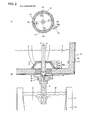
- Figs. 2(a) and (b) are schematic views of another continuous casting machine for carrying out the method of the present invention.
- (a) shows an A-A cross-section diagram in (b)
- (b) shows a longitudinal section of the continuous casting machine.
- the same reference signs are assigned to the parts substantially identical to those in the above-mentioned continuous casting machine shown in Figs. 1(a) and (b) .
- a third invention is the continuous casting method of molten metal according to the first invention or second invention, characterized in that an opening is provided in an upper end portion of the refractory-made structure 1 which is entirely submerged in molten metal, and a refractory-made stopper rod 14 is inserted through the opening from above the tundish, as shown in Figs. 2(a) and (b) .
- the refractory-made structure 1 provided with the opening in the upper end portion may have any of a cylindrical, conical or truncated cone shape.
- the level of an inner surface of upper end portion of the refractory-made structure 1 is preferably set to the same level of or at most 150 mm above the upper edge of outlet-side opening of the side holes 2 in order to make the refractory-made structure 1 compact.
- the diameter of the opening provided in the upper cover of the refractory-made structure 1 is preferably set to be larger by 1 to 20 mm than the diameter of the stopper rod 14.
- the stopper rod 14 generally performs the opening and closing of the molten metal passage extending from the inside of the tundish 5 to the submerged entry nozzle 4, the lower end of the stopper rod 14 is positioned at several mm to more than a dozen mm high above the bottom of the tundish 5 during casting, and the upper end portion thereof is connected to a lifting mechanism installed above an upper portion of the tundish 5.
- the stopper rod 14 is used for the purpose of preventing generation of the vortex associated with a swirling flow.
- the stopper rod 14 if it has a lifting function, may be used for molten metal level control in the mold 11. Otherwise, it may be used only to open and close the molten metal passage at the start of casting and at the end thereof.
- the molten metal level control in the mold 11 during casting is preferably performed using a sliding gate 9 provided between the submerged entry nozzle 4 and an upper nozzle 8.
- Figs. 3(a) and (b) are schematic views of the other continuous casting machine for carrying out the method of the present invention.
- (a) shows an A-A cross-sectional diagram in (b)
- (b) shows a longitudinal section of the continuous casting machine.
- the same reference signs are assigned to the parts substantially identical to those in the above-mentioned continuous casting machine shown in Figs. 1(a) and (b) .
- a fourth invention is the continuous casting method of molten metal according to the first invention or second invention, characterized in that no opening is provided in an upper end portion of the refractory-made structure 1 which is entirely submerged in molten metal in a tundish, as shown in Figs. 3(a) and (b) .
- molten steel is taken as the molten metal.
- Figs. 1 (a) and (b) are schematic views of a continuous casting machine for carrying out the method of the present invention as described above, wherein (a) shows an A-A cross-section diagram in (b), and (b) shows a longitudinal section of the continuous casting machine.
- the example shown in the same figures satisfies the conditions specified in the above-mentioned first invention and second invention.
- a hollow cylindrical type refractory-made structure 1 has an inner diameter of 400 mm, an outer diameter of 550 mm and an overall height of 1,200 mm, including a region having openings of side holes, and is made of alumina-silica type refractory.
- the mean inner radius R in the region having openings of side holes 2 is 200 mm.
- the molten metal level in the tundish 5 during steady state of casting is 200 mm below the upper end portion 7 of the refractory-made structure 1.
- molten steel 6 is given a circumferential velocity by passing through the side holes 2, increases the circumferential velocity according to the law of conservation of angular momentum when it passes through the upper nozzle 8 with a reduced inner diameter and the sliding gate 9, and generates an intensive swirling flow in the submerged entry nozzle 4.
- the swirling flow generated in the submerged entry nozzle 4 is uniformly and equally discharged through two outlet ports in the vicinity of the lower end of the submerged entry nozzle 4 by the effect of centrifugal force to generate a stable flow in the mold 11.
- the argon gas when argon gas is injected from the inner periphery of an upper fixed plate of the sliding gate 9 with dual plates, the argon gas forms an inverted cone shaped bubbles curtain by the centrifugal force acting on the molten steel 6. In that case, an effect such that non-metallic inclusions in the molten steel 6 flowing down across the bubbles curtain is effectively captured by bubbles, and floated and removed together with the bubbles in the mold 11 is also provided.
- the same effect can be obtained also when the argon gas is injected from the upper nozzle 8. Regardless of the injection site, the effect can be enhanced by injecting the gas from entire inner periphery, not from part thereof.
- the above-mentioned stabilization effect of flow in a mold facilitates the control of the flow velocity of molten steel in a mold to an appropriate range, a clean steel can be suitably obtained.
- the above-mentioned capturing and floating effect of inclusions by bubbles also promotes the cleaning of steel. Since the swirling flow stabilizes flow of molten metal in the vicinity of the inner wall of the submerged entry nozzle 4, the clogging of the submerged entry nozzle due to adherence of non-metallic inclusions is very unlikely.
- the refractory-made structure 1 shown in Figs. 1(a) and (b) is configured to prevent the slag in the tundish 5 from entering to the inside thereof by positioning the upper end portion 7 at a level higher than the molten metal level in the tundish 5. Therefore, even if the vortex is generated inside the refractory-made structure 1, the slag in the tundish 5 is never entrapped into the mold 11.
- Figs. 2 (a) and (b) are schematic views of another continuous casting machine for carrying out the method of the present invention as described above, wherein (a) shows an A-A cross-section diagram in (b), and (b) shows a longitudinal section of the continuous casting machine.
- the example shown in the same figures satisfies all conditions specified in the above-mentioned first to third inventions.
- the inner diameter in the region having openings of the side holes 2 is 550 mm at the lower edge of outlet-side opening of the side hole 2 and is 400 mm at the upper edge of outlet-side opening of the side hole 2.
- the outer diameter in the region having openings of the side holes 2 is 700 mm at the lower edge of inlet-side opening of the side hole 2 and is 550 mm at the upper edge of inlet-side opening of the side hole 2.
- the structure is 140 mm high to the inner surface of the upper cover and 180 mm high in all.
- the material of the refractory-made structure 1 is alumina-magnesia type refractory.
- the mean inner diameter 2R in the region having openings of the side holes 2 is 475 mm calculated by (550 [mm]+400 [mm])/2, and the mean inner radius R is 237.5 mm.
- the flow rate Q of molten steel during steady state of casting is 50 m 3 /hr.
- An opening with 110 mm in diameter is provided in an upper end portion 7 of the hollow truncated cone, and a stopper rod 14 with 100 mm in diameter is inserted to the vicinity of the upper nozzle 8 from above the tundish 5 through the opening.
- the molten metal level in the tundish 5 during steady state of casting is such that the refractory-made structure 1 is completely submerged.
- molten steel 6 passing through the side holes 2 is given a circumferential velocity, similarly to the case of the above-mentioned Inventive Example 1, increases the circumferential velocity according to the law of conservation of angular momentum when it passes through the upper nozzle 8 with a reduced inner diameter and the sliding gate 9, and generates an intensive swirling flow in the submerged entry nozzle 4.
- the swirling flow generated in the submerged entry nozzle 4 is uniformly and equally discharged through two outlet ports in the vicinity of the lower end of the submerged entry nozzle 4 by the effect of centrifugal force to generate a stable flow in mold.
- the above-mentioned stabilization effect of flow in a mold facilitates the control of the flow velocity of molten steel in a mold to an appropriate range, a clean steel can be suitably obtained.
- the above-mentioned capturing and floating effect of inclusions by bubbles also promotes the cleaning of steel. Further, since the swirling flow stabilizes the flow of molten metal in the vicinity of the inner wall of the submerged entry nozzle 4, the clogging of the submerged entry nozzle due to adherence of non-metallic inclusions is very unlikely.
- the existence of the stopper rod 14 prevents generation of the vortex resulting from swirling flow, and the possibility that the slag in the tundish 5 is carried into the mold 11 is extremely low.
- the flow rate of molten steel to the mold can be controlled by fully opening the sliding gate 9 so as to make the flow passage cross-section to a true circle shape, and adjusting the level of the stopper rod 14. In that case, a circumferentially equalized swirling flow can be generated in the submerged entry nozzle 4.
- Such a circumferentially equalized swirling flow leads to further uniformed and stabilized flow of molten steel in a mold, compared with Inventive Example 1.
- FIGs. 3(a) and (b) are schematic views of the other continuous casting machine for carrying out the method of the present invention as described above, wherein (a) is an A-A cross-section diagram in (b), and (b) is a longitudinal section of the continuous casting machine.
- the example shown in the same figures satisfies all conditions regulated in the above-mentioned first, second and fourth inventions.
- the inner diameter in the region having openings of the side holes 2 is 550 mm at the lower edge of outlet-side opening of the side hole 2 and is 400 mm at the upper edge thereof.
- the outer diameter in the region having openings of the side holes 2 is 700 mm at the lower edge of inlet-side opening of the side hole 2 and is 550 mm at the upper edge thereof.
- the structure is 140 mm high to the inner surface of the upper cover and 180 mm high in all.
- the material of the refractory-made structure 1 is alumina-magnesia type refractory.
- the mean inner diameter 2R in the region having openings of the side holes 2 is 475 mm calculated by (550 [mm]+400 [mm])/2, and the mean inner radius R is 237.5 mm.
- the flow rate Q of molten steel during steady state of casting is 60 m 3 /hr.
- molten steel 6 passing through the side holes 2 is given a circumferential velocity, similarly to the case of the above-mentioned Inventive Example 1, increases the circumferential velocity according to the law of conservation of angular momentum when it passes through the upper nozzle 8 with reduced inner diameter and the sliding gate 9, and generates an intensive swirling flow in the submerged entry nozzle 4.
- the swirling flow generated in the submerged entry nozzle 4 is uniformly and equally discharged through two outlet ports in the vicinity of the lower end of the submerged entry nozzle 4 by the effect of centrifugal force to generate a stable flow in mold.
- the argon gas When argon gas is injected from the inner periphery of the upper nozzle 8, the argon gas forms an inverted cone shaped bubbles curtain by the centrifugal force acting on the molten steel 6. Therefore, an effect such that the non-metallic inclusions in the molten steel 6 flowing down across the bubbles curtain is effectively captured by bubbles, and floated and removed together with the bubbles in the mold 11 is also produced.
- the same effect can be obtained when the argon gas is injected from the sliding gate 9. Regardless of the injection site, this effect can be enhanced by injecting the gas from entire inner periphery, not from part thereof.
- the above-mentioned stabilization effect of flow in a mold facilitates the control of the flow velocity of molten steel in a mold to an appropriate range, a clean steel can be suitably obtained.
- the above-mentioned capturing and floating effect of inclusions by bubbles also promotes the cleaning of steel. Further, since the swirling flow stabilizes the flow of molten metal in the vicinity of the inner wall of the submerged entry nozzle 4, the clogging of the submerged entry nozzle due to adherence of non-metallic inclusions is very unlikely.
- Inventive Example 3 since no opening is provided in the upper end portion 7 of the hollow truncated cone, generation of the vortex resulting from swirling flow is prevented, and the possibility that the slag in the tundish 5 is entrapped into the mold 11 is extremely low.
- Inventive Example 3 is low in cost since the refractory-made structure 1 is small, compared with Inventive Example 1. Further, Inventive Example 3 is also superior in cost to Inventive Example 2 since the stopper rod 14 is not used.
- the continuous casting method of molten metal of the present invention shown in the above-mentioned Inventive Examples 1 to 3 can stabilize the flow in the vicinity of the inner wall of the submerged entry nozzle 4 to suppress the adherence of non-metallic inclusions to the inner wall since the swirling flow can be generated in the submerged entry nozzle 4, compared with an ordinary continuous casting method without installation of the refractory-made structure 1. Consequently, the method of the present invention exerts a high effect on improvement in cast slab quality and productivity of continuous casting through the stabilization of the flow in a mold.
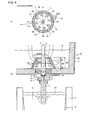
- Figs. 4(a) and (b) are schematic views of a continuous casting machine as a comparative example to the present invention, wherein (a) shows an A-A cross-section diagram in (b), and (b) shows a longitudinal section of the continuous casting machine.
- the same reference signs are assigned to the parts substantially identical to the above-mentioned continuous casting machine shown in Figs. 2(a) and (b) .
- the example shown in the same figures does not satisfy the conditions specified in the first invention.
- the inner diameter in the region having openings of the side holes 2 is 600 mm at the lower edge of outlet-side opening of the side hole 2 and is 400 mm at the upper edge thereof.
- the outer diameter in the region having openings of the side holes 2 is 700 mm at the lower edge of inlet-side opening of the side hole 2 and is 500 mm at the upper edge thereof.
- the structure is 350 mm high to the inner surface of the upper cover and 400 mm high in all, being formed of alumina-magnesia type refractory.
- the mean inner diameter 2R in the region having openings of the side holes 2 is 500 mm calculated by (600 [mm]+400 [mm])/2, and the mean inner radius R is 250 mm.
- the flow rate Q of molten steel during steady state of casting is 32 m 3 /hr.
- An opening with 110 mm in diameter is provided in an upper end portion 7 of the hollow truncated cone, and a stopper rod 14 with 100 mm in diameter is inserted to the vicinity of the upper nozzle 8 from above the tundish 5 through the opening.
- the molten metal level in the tundish 5 during steady state of operation is such that the refractory-made structure 1 is completely submerged.
- Figs. 5(a) and (b) are schematic views of another continuous casting machine as a comparative example to the present invention, wherein (a) shows an A-A cross-section diagram in (b), and (b) shows a longitudinal section of the continuous casting machine.
- the same reference signs are assigned to the parts substantially identical to the above-mentioned continuous casting machine shown in Figs. 1(a) and (b) .
- the example shown in the same figures does not satisfy the conditions specified in the above-mentioned first to third inventions.
- a hollow cylindrical type refractory-made structure 1 has an inner diameter of 400 mm, an outer diameter of 550 mm, and an overall height of 1250 mm, including a region having openings of side holes, and is formed of alumina-silica type refractory. Namely, the mean inner radius R in the region having openings of the side holes 2 is 200 mm.
- the molten metal level in the tundish 5 during steady state of continuous casting is 100 mm below an upper end portion 7 of the refractory-made structure 1.
- the flow rate Q of molten steel during steady state of casting is 65 m 3 /hr.
- the continuous casting method of molten metal of the present invention is a technique extensively applicable in the field of casting, where stabilization of continuous casting and achieving high-level cleanliness of cast slab are sought after, by an inexpensive device and a simple method.
Landscapes
- Engineering & Computer Science (AREA)
- Mechanical Engineering (AREA)
- Continuous Casting (AREA)
- Molds, Cores, And Manufacturing Methods Thereof (AREA)
Priority Applications (1)
| Application Number | Priority Date | Filing Date | Title |
|---|---|---|---|
| PL10828046T PL2497585T3 (pl) | 2009-11-06 | 2010-10-01 | Sposób ciągłego odlewania stopionego metalu |
Applications Claiming Priority (2)
| Application Number | Priority Date | Filing Date | Title |
|---|---|---|---|
| JP2009255222 | 2009-11-06 | ||
| PCT/JP2010/005916 WO2011055484A1 (ja) | 2009-11-06 | 2010-10-01 | 溶融金属の連続鋳造方法 |
Publications (3)
| Publication Number | Publication Date |
|---|---|
| EP2497585A1 true EP2497585A1 (de) | 2012-09-12 |
| EP2497585A4 EP2497585A4 (de) | 2016-12-21 |
| EP2497585B1 EP2497585B1 (de) | 2017-11-29 |
Family
ID=43969728
Family Applications (1)
| Application Number | Title | Priority Date | Filing Date |
|---|---|---|---|
| EP10828046.2A Not-in-force EP2497585B1 (de) | 2009-11-06 | 2010-10-01 | Stranggussverfahren für geschmolzenes metall |
Country Status (7)
| Country | Link |
|---|---|
| EP (1) | EP2497585B1 (de) |
| JP (1) | JP5440610B2 (de) |
| KR (1) | KR101384019B1 (de) |
| CN (1) | CN102781605B (de) |
| ES (1) | ES2658172T3 (de) |
| PL (1) | PL2497585T3 (de) |
| WO (1) | WO2011055484A1 (de) |
Cited By (1)
| Publication number | Priority date | Publication date | Assignee | Title |
|---|---|---|---|---|
| CN106312033A (zh) * | 2015-07-02 | 2017-01-11 | 维苏威坩埚公司 | 中间包出口稳流器 |
Families Citing this family (10)
| Publication number | Priority date | Publication date | Assignee | Title |
|---|---|---|---|---|
| JP5768751B2 (ja) * | 2012-03-29 | 2015-08-26 | 新日鐵住金株式会社 | 溶融金属の連続鋳造方法 |
| JP6354341B2 (ja) * | 2014-05-30 | 2018-07-11 | 新日鐵住金株式会社 | 溶融金属への旋回流付与方法 |
| JP6331810B2 (ja) * | 2014-07-18 | 2018-05-30 | 新日鐵住金株式会社 | 金属の連続鋳造方法 |
| CN105965003B (zh) * | 2016-07-05 | 2018-05-29 | 东北大学 | 一种水口旋流发生装置及水口旋流连铸方法 |
| CN108247033B (zh) * | 2018-01-17 | 2020-07-21 | 武汉科技大学 | 一种连铸中间包用旋流上水口 |
| CN109108240B (zh) * | 2018-10-31 | 2024-08-02 | 武汉科技大学 | 一种连铸中间包用气动旋流上水口座砖 |
| KR102184274B1 (ko) * | 2019-03-04 | 2020-11-30 | 경북대학교 산학협력단 | 연속 주조 공정 중 래들 및 턴디쉬의 자유 표면의 부유물 혼입 방지 장치 |
| CN110773731A (zh) * | 2019-11-08 | 2020-02-11 | 德龙钢铁有限公司 | 一种改善结晶器流场的连铸用浸入式侧喷水口 |
| CN118893187B (zh) * | 2024-08-26 | 2025-02-25 | 中铁北赛电工有限公司 | 一种铜铬锆合金连铸用电磁调控装置 |
| CN119702988B (zh) * | 2024-12-24 | 2026-05-05 | 东北大学 | 一种中间包电磁旋流与旋流塞棒联控连铸装置及方法 |
Family Cites Families (13)
| Publication number | Priority date | Publication date | Assignee | Title |
|---|---|---|---|---|
| JPS54125134A (en) * | 1978-03-24 | 1979-09-28 | Nippon Steel Corp | Prevention of nozzle clogging for casting |
| JPS62149914A (ja) | 1985-12-19 | 1987-07-03 | Teijin Ltd | 改質ポリエステル繊維 |
| JPS632540A (ja) * | 1986-06-23 | 1988-01-07 | Nippon Kokan Kk <Nkk> | 溶湯流口を備えた溶湯容器 |
| JPS6316856A (ja) * | 1986-07-09 | 1988-01-23 | Nippon Kokan Kk <Nkk> | 溶湯流出口を備えた溶湯容器 |
| JP3027645B2 (ja) * | 1991-12-18 | 2000-04-04 | 日新製鋼株式会社 | 連続鋳造用浸漬ノズル |
| WO1999015291A1 (en) | 1997-09-22 | 1999-04-01 | Katsukiyo Marukawa | Immersion nozzle |
| JP3207793B2 (ja) | 1997-10-21 | 2001-09-10 | 品川白煉瓦株式会社 | 連続鋳造用浸漬ノズル |
| JPH11239852A (ja) * | 1998-02-24 | 1999-09-07 | Sumitomo Metal Ind Ltd | 連続鋳造用浸漬ノズルおよび連続鋳造方法 |
| JP3515762B2 (ja) | 2001-02-21 | 2004-04-05 | 住友金属工業株式会社 | 連続鋳造用浸漬ノズル並びに連続鋳造方法 |
| WO2005070589A1 (ja) * | 2004-01-23 | 2005-08-04 | Sumitomo Metal Industries, Ltd | 連続鋳造用浸漬ノズル及びそれを用いた連続鋳造方法 |
| JP4419934B2 (ja) * | 2005-09-07 | 2010-02-24 | 住友金属工業株式会社 | 溶融金属の連続鋳造方法 |
| JP4670762B2 (ja) * | 2006-07-27 | 2011-04-13 | 住友金属工業株式会社 | 溶融金属の連続鋳造方法 |
| JP5141872B2 (ja) | 2007-05-29 | 2013-02-13 | 日産自動車株式会社 | 燃料電池システム及びその制御方法 |
-
2010
- 2010-10-01 ES ES10828046.2T patent/ES2658172T3/es active Active
- 2010-10-01 CN CN201080050324.6A patent/CN102781605B/zh active Active
- 2010-10-01 JP JP2011539256A patent/JP5440610B2/ja active Active
- 2010-10-01 KR KR1020127013193A patent/KR101384019B1/ko active Active
- 2010-10-01 PL PL10828046T patent/PL2497585T3/pl unknown
- 2010-10-01 EP EP10828046.2A patent/EP2497585B1/de not_active Not-in-force
- 2010-10-01 WO PCT/JP2010/005916 patent/WO2011055484A1/ja not_active Ceased
Non-Patent Citations (1)
| Title |
|---|
| See references of WO2011055484A1 * |
Cited By (2)
| Publication number | Priority date | Publication date | Assignee | Title |
|---|---|---|---|---|
| CN106312033A (zh) * | 2015-07-02 | 2017-01-11 | 维苏威坩埚公司 | 中间包出口稳流器 |
| US10456832B2 (en) | 2015-07-02 | 2019-10-29 | Vesuvius Usa Corporation | Tundish outlet modifier |
Also Published As
| Publication number | Publication date |
|---|---|
| PL2497585T3 (pl) | 2018-04-30 |
| KR101384019B1 (ko) | 2014-04-09 |
| CN102781605B (zh) | 2014-11-05 |
| KR20120079476A (ko) | 2012-07-12 |
| EP2497585A4 (de) | 2016-12-21 |
| ES2658172T3 (es) | 2018-03-08 |
| EP2497585B1 (de) | 2017-11-29 |
| CN102781605A (zh) | 2012-11-14 |
| JP5440610B2 (ja) | 2014-03-12 |
| WO2011055484A1 (ja) | 2011-05-12 |
| JPWO2011055484A1 (ja) | 2013-03-21 |
Similar Documents
| Publication | Publication Date | Title |
|---|---|---|
| EP2497585B1 (de) | Stranggussverfahren für geschmolzenes metall | |
| EP0662021B1 (de) | Feuerfester artikel zur verhinderung der wirbelung in metallurgischen gefässen | |
| US5882577A (en) | Tundish | |
| EP1541258B1 (de) | Giessdüse | |
| CN107073574A (zh) | 冲击垫、包括冲击垫的浇注盘和设备、及其使用方法 | |
| JP4419934B2 (ja) | 溶融金属の連続鋳造方法 | |
| JP6354341B2 (ja) | 溶融金属への旋回流付与方法 | |
| JP4670762B2 (ja) | 溶融金属の連続鋳造方法 | |
| US8591802B2 (en) | Vortex inhibitor | |
| EP1687110B1 (de) | Giessdüse mit mehreren auslässen | |
| US20060169728A1 (en) | Submerged entry nozzle with dynamic stabilization | |
| JP7230634B2 (ja) | 旋回流付与装置、タンディッシュ、鋼の連続鋳造システム及び鋼の連続鋳造方法 | |
| JP4556804B2 (ja) | 溶融金属の注入管および注入方法 | |
| JP4289182B2 (ja) | タンディッシュ用注入管 | |
| JP2005199325A (ja) | 金属の連続鋳造方法 | |
| JP4644168B2 (ja) | 下注ぎ方式の注湯管及び注湯方法 | |
| JP2006088219A (ja) | 溶融金属注湯ノズル及びその設置構造並びに溶融金属の注湯方法 | |
| KR102949056B1 (ko) | 와류를 저감시키는 레이들 | |
| CN105451912B (zh) | 铸桶底部及铸桶 | |
| CA2442857A1 (en) | Improved regulation of a stream of molten metal | |
| WO2025248870A1 (ja) | 浸漬ノズル | |
| JPH10263765A (ja) | 溶融金属流制御方法及びそのための鋳造用ノズル | |
| JP2021049546A (ja) | 溶融金属の注湯装置 |
Legal Events
| Date | Code | Title | Description |
|---|---|---|---|
| PUAI | Public reference made under article 153(3) epc to a published international application that has entered the european phase |
Free format text: ORIGINAL CODE: 0009012 |
|
| 17P | Request for examination filed |
Effective date: 20120410 |
|
| AK | Designated contracting states |
Kind code of ref document: A1 Designated state(s): AL AT BE BG CH CY CZ DE DK EE ES FI FR GB GR HR HU IE IS IT LI LT LU LV MC MK MT NL NO PL PT RO RS SE SI SK SM TR |
|
| RAP1 | Party data changed (applicant data changed or rights of an application transferred) |
Owner name: NIPPON STEEL & SUMITOMO METAL CORPORATION |
|
| DAX | Request for extension of the european patent (deleted) | ||
| RA4 | Supplementary search report drawn up and despatched (corrected) |
Effective date: 20161122 |
|
| RIC1 | Information provided on ipc code assigned before grant |
Ipc: B22D 11/10 20060101AFI20161116BHEP Ipc: B22D 41/50 20060101ALI20161116BHEP |
|
| GRAP | Despatch of communication of intention to grant a patent |
Free format text: ORIGINAL CODE: EPIDOSNIGR1 |
|
| STAA | Information on the status of an ep patent application or granted ep patent |
Free format text: STATUS: GRANT OF PATENT IS INTENDED |
|
| RIC1 | Information provided on ipc code assigned before grant |
Ipc: B22D 41/50 20060101ALI20170622BHEP Ipc: B22D 11/10 20060101AFI20170622BHEP Ipc: B22D 41/08 20060101ALI20170622BHEP Ipc: B22D 11/103 20060101ALI20170622BHEP |
|
| INTG | Intention to grant announced |
Effective date: 20170714 |
|
| GRAS | Grant fee paid |
Free format text: ORIGINAL CODE: EPIDOSNIGR3 |
|
| GRAA | (expected) grant |
Free format text: ORIGINAL CODE: 0009210 |
|
| STAA | Information on the status of an ep patent application or granted ep patent |
Free format text: STATUS: THE PATENT HAS BEEN GRANTED |
|
| AK | Designated contracting states |
Kind code of ref document: B1 Designated state(s): AL AT BE BG CH CY CZ DE DK EE ES FI FR GB GR HR HU IE IS IT LI LT LU LV MC MK MT NL NO PL PT RO RS SE SI SK SM TR |
|
| REG | Reference to a national code |
Ref country code: CH Ref legal event code: EP |
|
| REG | Reference to a national code |
Ref country code: AT Ref legal event code: REF Ref document number: 949923 Country of ref document: AT Kind code of ref document: T Effective date: 20171215 |
|
| REG | Reference to a national code |
Ref country code: IE Ref legal event code: FG4D |
|
| REG | Reference to a national code |
Ref country code: DE Ref legal event code: R096 Ref document number: 602010047085 Country of ref document: DE |
|
| REG | Reference to a national code |
Ref country code: NL Ref legal event code: FP |
|
| REG | Reference to a national code |
Ref country code: SE Ref legal event code: TRGR |
|
| REG | Reference to a national code |
Ref country code: ES Ref legal event code: FG2A Ref document number: 2658172 Country of ref document: ES Kind code of ref document: T3 Effective date: 20180308 |
|
| REG | Reference to a national code |
Ref country code: LT Ref legal event code: MG4D |
|
| PG25 | Lapsed in a contracting state [announced via postgrant information from national office to epo] |
Ref country code: NO Free format text: LAPSE BECAUSE OF FAILURE TO SUBMIT A TRANSLATION OF THE DESCRIPTION OR TO PAY THE FEE WITHIN THE PRESCRIBED TIME-LIMIT Effective date: 20180228 Ref country code: LT Free format text: LAPSE BECAUSE OF FAILURE TO SUBMIT A TRANSLATION OF THE DESCRIPTION OR TO PAY THE FEE WITHIN THE PRESCRIBED TIME-LIMIT Effective date: 20171129 Ref country code: FI Free format text: LAPSE BECAUSE OF FAILURE TO SUBMIT A TRANSLATION OF THE DESCRIPTION OR TO PAY THE FEE WITHIN THE PRESCRIBED TIME-LIMIT Effective date: 20171129 |
|
| PG25 | Lapsed in a contracting state [announced via postgrant information from national office to epo] |
Ref country code: RS Free format text: LAPSE BECAUSE OF FAILURE TO SUBMIT A TRANSLATION OF THE DESCRIPTION OR TO PAY THE FEE WITHIN THE PRESCRIBED TIME-LIMIT Effective date: 20171129 Ref country code: LV Free format text: LAPSE BECAUSE OF FAILURE TO SUBMIT A TRANSLATION OF THE DESCRIPTION OR TO PAY THE FEE WITHIN THE PRESCRIBED TIME-LIMIT Effective date: 20171129 Ref country code: BG Free format text: LAPSE BECAUSE OF FAILURE TO SUBMIT A TRANSLATION OF THE DESCRIPTION OR TO PAY THE FEE WITHIN THE PRESCRIBED TIME-LIMIT Effective date: 20180228 Ref country code: HR Free format text: LAPSE BECAUSE OF FAILURE TO SUBMIT A TRANSLATION OF THE DESCRIPTION OR TO PAY THE FEE WITHIN THE PRESCRIBED TIME-LIMIT Effective date: 20171129 Ref country code: GR Free format text: LAPSE BECAUSE OF FAILURE TO SUBMIT A TRANSLATION OF THE DESCRIPTION OR TO PAY THE FEE WITHIN THE PRESCRIBED TIME-LIMIT Effective date: 20180301 |
|
| PG25 | Lapsed in a contracting state [announced via postgrant information from national office to epo] |
Ref country code: CZ Free format text: LAPSE BECAUSE OF FAILURE TO SUBMIT A TRANSLATION OF THE DESCRIPTION OR TO PAY THE FEE WITHIN THE PRESCRIBED TIME-LIMIT Effective date: 20171129 Ref country code: DK Free format text: LAPSE BECAUSE OF FAILURE TO SUBMIT A TRANSLATION OF THE DESCRIPTION OR TO PAY THE FEE WITHIN THE PRESCRIBED TIME-LIMIT Effective date: 20171129 Ref country code: EE Free format text: LAPSE BECAUSE OF FAILURE TO SUBMIT A TRANSLATION OF THE DESCRIPTION OR TO PAY THE FEE WITHIN THE PRESCRIBED TIME-LIMIT Effective date: 20171129 Ref country code: CY Free format text: LAPSE BECAUSE OF FAILURE TO SUBMIT A TRANSLATION OF THE DESCRIPTION OR TO PAY THE FEE WITHIN THE PRESCRIBED TIME-LIMIT Effective date: 20171129 Ref country code: SK Free format text: LAPSE BECAUSE OF FAILURE TO SUBMIT A TRANSLATION OF THE DESCRIPTION OR TO PAY THE FEE WITHIN THE PRESCRIBED TIME-LIMIT Effective date: 20171129 |
|
| REG | Reference to a national code |
Ref country code: DE Ref legal event code: R097 Ref document number: 602010047085 Country of ref document: DE |
|
| PG25 | Lapsed in a contracting state [announced via postgrant information from national office to epo] |
Ref country code: RO Free format text: LAPSE BECAUSE OF FAILURE TO SUBMIT A TRANSLATION OF THE DESCRIPTION OR TO PAY THE FEE WITHIN THE PRESCRIBED TIME-LIMIT Effective date: 20171129 Ref country code: SM Free format text: LAPSE BECAUSE OF FAILURE TO SUBMIT A TRANSLATION OF THE DESCRIPTION OR TO PAY THE FEE WITHIN THE PRESCRIBED TIME-LIMIT Effective date: 20171129 |
|
| REG | Reference to a national code |
Ref country code: FR Ref legal event code: PLFP Year of fee payment: 9 |
|
| PLBE | No opposition filed within time limit |
Free format text: ORIGINAL CODE: 0009261 |
|
| STAA | Information on the status of an ep patent application or granted ep patent |
Free format text: STATUS: NO OPPOSITION FILED WITHIN TIME LIMIT |
|
| 26N | No opposition filed |
Effective date: 20180830 |
|
| PG25 | Lapsed in a contracting state [announced via postgrant information from national office to epo] |
Ref country code: SI Free format text: LAPSE BECAUSE OF FAILURE TO SUBMIT A TRANSLATION OF THE DESCRIPTION OR TO PAY THE FEE WITHIN THE PRESCRIBED TIME-LIMIT Effective date: 20171129 |
|
| REG | Reference to a national code |
Ref country code: CH Ref legal event code: PL |
|
| REG | Reference to a national code |
Ref country code: DE Ref legal event code: R082 Ref document number: 602010047085 Country of ref document: DE Representative=s name: PATENTANWALTSKANZLEI MEYER, DE Ref country code: DE Ref legal event code: R081 Ref document number: 602010047085 Country of ref document: DE Owner name: NIPPON STEEL CORP., JP Free format text: FORMER OWNER: NIPPON STEEL & SUMITOMO METAL CORPORATION, TOKYO, JP |
|
| PG25 | Lapsed in a contracting state [announced via postgrant information from national office to epo] |
Ref country code: LU Free format text: LAPSE BECAUSE OF NON-PAYMENT OF DUE FEES Effective date: 20181001 Ref country code: MC Free format text: LAPSE BECAUSE OF FAILURE TO SUBMIT A TRANSLATION OF THE DESCRIPTION OR TO PAY THE FEE WITHIN THE PRESCRIBED TIME-LIMIT Effective date: 20171129 |
|
| REG | Reference to a national code |
Ref country code: IE Ref legal event code: MM4A |
|
| PG25 | Lapsed in a contracting state [announced via postgrant information from national office to epo] |
Ref country code: LI Free format text: LAPSE BECAUSE OF NON-PAYMENT OF DUE FEES Effective date: 20181031 Ref country code: CH Free format text: LAPSE BECAUSE OF NON-PAYMENT OF DUE FEES Effective date: 20181031 |
|
| PG25 | Lapsed in a contracting state [announced via postgrant information from national office to epo] |
Ref country code: IE Free format text: LAPSE BECAUSE OF NON-PAYMENT OF DUE FEES Effective date: 20181001 |
|
| PGFP | Annual fee paid to national office [announced via postgrant information from national office to epo] |
Ref country code: NL Payment date: 20190912 Year of fee payment: 10 Ref country code: FR Payment date: 20190913 Year of fee payment: 10 |
|
| PGFP | Annual fee paid to national office [announced via postgrant information from national office to epo] |
Ref country code: BE Payment date: 20190917 Year of fee payment: 10 Ref country code: PL Payment date: 20190917 Year of fee payment: 10 |
|
| PGFP | Annual fee paid to national office [announced via postgrant information from national office to epo] |
Ref country code: GB Payment date: 20190926 Year of fee payment: 10 |
|
| PG25 | Lapsed in a contracting state [announced via postgrant information from national office to epo] |
Ref country code: MT Free format text: LAPSE BECAUSE OF NON-PAYMENT OF DUE FEES Effective date: 20181001 |
|
| PGFP | Annual fee paid to national office [announced via postgrant information from national office to epo] |
Ref country code: SE Payment date: 20191010 Year of fee payment: 10 Ref country code: DE Payment date: 20190917 Year of fee payment: 10 |
|
| PGFP | Annual fee paid to national office [announced via postgrant information from national office to epo] |
Ref country code: IT Payment date: 20191009 Year of fee payment: 10 Ref country code: ES Payment date: 20191104 Year of fee payment: 10 |
|
| PG25 | Lapsed in a contracting state [announced via postgrant information from national office to epo] |
Ref country code: TR Free format text: LAPSE BECAUSE OF FAILURE TO SUBMIT A TRANSLATION OF THE DESCRIPTION OR TO PAY THE FEE WITHIN THE PRESCRIBED TIME-LIMIT Effective date: 20171129 |
|
| PGFP | Annual fee paid to national office [announced via postgrant information from national office to epo] |
Ref country code: AT Payment date: 20190925 Year of fee payment: 10 |
|
| PG25 | Lapsed in a contracting state [announced via postgrant information from national office to epo] |
Ref country code: PT Free format text: LAPSE BECAUSE OF FAILURE TO SUBMIT A TRANSLATION OF THE DESCRIPTION OR TO PAY THE FEE WITHIN THE PRESCRIBED TIME-LIMIT Effective date: 20171129 |
|
| PG25 | Lapsed in a contracting state [announced via postgrant information from national office to epo] |
Ref country code: MK Free format text: LAPSE BECAUSE OF NON-PAYMENT OF DUE FEES Effective date: 20171129 Ref country code: HU Free format text: LAPSE BECAUSE OF FAILURE TO SUBMIT A TRANSLATION OF THE DESCRIPTION OR TO PAY THE FEE WITHIN THE PRESCRIBED TIME-LIMIT; INVALID AB INITIO Effective date: 20101001 |
|
| PG25 | Lapsed in a contracting state [announced via postgrant information from national office to epo] |
Ref country code: IS Free format text: LAPSE BECAUSE OF FAILURE TO SUBMIT A TRANSLATION OF THE DESCRIPTION OR TO PAY THE FEE WITHIN THE PRESCRIBED TIME-LIMIT Effective date: 20180329 Ref country code: AL Free format text: LAPSE BECAUSE OF FAILURE TO SUBMIT A TRANSLATION OF THE DESCRIPTION OR TO PAY THE FEE WITHIN THE PRESCRIBED TIME-LIMIT Effective date: 20171129 |
|
| REG | Reference to a national code |
Ref country code: AT Ref legal event code: UEP Ref document number: 949923 Country of ref document: AT Kind code of ref document: T Effective date: 20171129 |
|
| REG | Reference to a national code |
Ref country code: DE Ref legal event code: R119 Ref document number: 602010047085 Country of ref document: DE |
|
| REG | Reference to a national code |
Ref country code: SE Ref legal event code: EUG |
|
| REG | Reference to a national code |
Ref country code: NL Ref legal event code: MM Effective date: 20201101 |
|
| REG | Reference to a national code |
Ref country code: AT Ref legal event code: MM01 Ref document number: 949923 Country of ref document: AT Kind code of ref document: T Effective date: 20201001 |
|
| GBPC | Gb: european patent ceased through non-payment of renewal fee |
Effective date: 20201001 |
|
| REG | Reference to a national code |
Ref country code: BE Ref legal event code: MM Effective date: 20201031 |
|
| PG25 | Lapsed in a contracting state [announced via postgrant information from national office to epo] |
Ref country code: FR Free format text: LAPSE BECAUSE OF NON-PAYMENT OF DUE FEES Effective date: 20201031 Ref country code: DE Free format text: LAPSE BECAUSE OF NON-PAYMENT OF DUE FEES Effective date: 20210501 Ref country code: NL Free format text: LAPSE BECAUSE OF NON-PAYMENT OF DUE FEES Effective date: 20201101 |
|
| PG25 | Lapsed in a contracting state [announced via postgrant information from national office to epo] |
Ref country code: BE Free format text: LAPSE BECAUSE OF NON-PAYMENT OF DUE FEES Effective date: 20201031 Ref country code: AT Free format text: LAPSE BECAUSE OF NON-PAYMENT OF DUE FEES Effective date: 20201001 Ref country code: SE Free format text: LAPSE BECAUSE OF NON-PAYMENT OF DUE FEES Effective date: 20201002 Ref country code: GB Free format text: LAPSE BECAUSE OF NON-PAYMENT OF DUE FEES Effective date: 20201001 |
|
| PG25 | Lapsed in a contracting state [announced via postgrant information from national office to epo] |
Ref country code: IT Free format text: LAPSE BECAUSE OF NON-PAYMENT OF DUE FEES Effective date: 20201001 |
|
| REG | Reference to a national code |
Ref country code: ES Ref legal event code: FD2A Effective date: 20220120 |
|
| PG25 | Lapsed in a contracting state [announced via postgrant information from national office to epo] |
Ref country code: ES Free format text: LAPSE BECAUSE OF NON-PAYMENT OF DUE FEES Effective date: 20201002 |
|
| PG25 | Lapsed in a contracting state [announced via postgrant information from national office to epo] |
Ref country code: PL Free format text: LAPSE BECAUSE OF NON-PAYMENT OF DUE FEES Effective date: 20201001 |