EP2497603A2 - Outil de fixation d'un goujon sur une surface - Google Patents
Outil de fixation d'un goujon sur une surface Download PDFInfo
- Publication number
- EP2497603A2 EP2497603A2 EP12250036A EP12250036A EP2497603A2 EP 2497603 A2 EP2497603 A2 EP 2497603A2 EP 12250036 A EP12250036 A EP 12250036A EP 12250036 A EP12250036 A EP 12250036A EP 2497603 A2 EP2497603 A2 EP 2497603A2
- Authority
- EP
- European Patent Office
- Prior art keywords
- tool
- applicator
- fastener
- contact surface
- housing portion
- Prior art date
- Legal status (The legal status is an assumption and is not a legal conclusion. Google has not performed a legal analysis and makes no representation as to the accuracy of the status listed.)
- Granted
Links
Images




Classifications
-
- B—PERFORMING OPERATIONS; TRANSPORTING
- B25—HAND TOOLS; PORTABLE POWER-DRIVEN TOOLS; MANIPULATORS
- B25B—TOOLS OR BENCH DEVICES NOT OTHERWISE PROVIDED FOR, FOR FASTENING, CONNECTING, DISENGAGING, OR HOLDING
- B25B31/00—Hand tools for applying fasteners
-
- B—PERFORMING OPERATIONS; TRANSPORTING
- B25—HAND TOOLS; PORTABLE POWER-DRIVEN TOOLS; MANIPULATORS
- B25B—TOOLS OR BENCH DEVICES NOT OTHERWISE PROVIDED FOR, FOR FASTENING, CONNECTING, DISENGAGING, OR HOLDING
- B25B5/00—Clamps
- B25B5/06—Arrangements for positively actuating jaws
-
- Y—GENERAL TAGGING OF NEW TECHNOLOGICAL DEVELOPMENTS; GENERAL TAGGING OF CROSS-SECTIONAL TECHNOLOGIES SPANNING OVER SEVERAL SECTIONS OF THE IPC; TECHNICAL SUBJECTS COVERED BY FORMER USPC CROSS-REFERENCE ART COLLECTIONS [XRACs] AND DIGESTS
- Y10—TECHNICAL SUBJECTS COVERED BY FORMER USPC
- Y10T—TECHNICAL SUBJECTS COVERED BY FORMER US CLASSIFICATION
- Y10T29/00—Metal working
- Y10T29/49—Method of mechanical manufacture
- Y10T29/49826—Assembling or joining
- Y10T29/49908—Joining by deforming
- Y10T29/49915—Overedge assembling of seated part
-
- Y—GENERAL TAGGING OF NEW TECHNOLOGICAL DEVELOPMENTS; GENERAL TAGGING OF CROSS-SECTIONAL TECHNOLOGIES SPANNING OVER SEVERAL SECTIONS OF THE IPC; TECHNICAL SUBJECTS COVERED BY FORMER USPC CROSS-REFERENCE ART COLLECTIONS [XRACs] AND DIGESTS
- Y10—TECHNICAL SUBJECTS COVERED BY FORMER USPC
- Y10T—TECHNICAL SUBJECTS COVERED BY FORMER US CLASSIFICATION
- Y10T29/00—Metal working
- Y10T29/53—Means to assemble or disassemble
- Y10T29/53709—Overedge assembling means
- Y10T29/53783—Clip applier
Definitions
- the invention generally relates to systems and methods for attaching a stud to a surface.
- threaded studs can be bonded to the surface using an epoxy adhesive.
- the tool includes a housing portion configured to releasably receive the fastener and an applicator.
- the applicator has at least two legs.
- the tool further includes an actuating portion slidingly connected to the housing portion and comprising one or more projections. Movement of the actuating portion towards the contact surface presses the fastener against the contact surface and bends the at least two legs of the applicator towards the contact surface.
- the tool may further comprise one or more biasing elements, wherein movement of the actuating portion towards the contact surface biases each biasing element.
- the tool may further comprise one or more rods fixedly attached to the housing portion, at least a portion of the rods being disposed in the actuating portion.
- the tool may further comprise one or more stops respectively positioned at ends of the one of the one .or more rods and configured to prevent the actuating portion from disconnecting from the housing portion.
- the housing portion may comprise a lower surface defining a channel for receiving at least a portion of the applicator.
- the housing portion may comprise an inner surface defining a receptacle for receiving at least a portion of the fastener.
- the housing portion may comprise a gripper configurable to retain at least a portion of the fastener within the receptacle.
- the tool may further comprise means for attaching and detaching the fastener from the gripper. Movement of the actuating portion towards the contact surface may cause the housing portion to press the fastener against the contact surface.
- an automatic stud applying machine comprising a tool as claimed or described herein.
- the machine may further comprise at least one motor configured to position the tool with respect to the contact surface and to move the actuating portion towards the contact surface.
- the machine may further comprise at least one motor configured to position the fastener and applicator with respect to the housing.
- the machine may further comprise a processor configured to control the at least one motor.
- the fastener has a base and a shaft.
- the applicator has at least two legs and means to releasably receive the shaft of the fastener.
- the tool includes a housing portion having a bearing surface and a receptacle.
- the bearing surface is configured to contact at least a portion of the applicator.
- the receptacle is configured to releasably receive a portion of the fastener shaft.
- the tool further includes an actuating portion slidingly connected to the housing portion.
- the actuating portion has at least one projection configured to contact and bend the at least two legs of the applicator towards the contact surface.
- the housing portion is configured to press the base of the fastener against the contact surface.
- the tool may further comprise one or more springs configured to press the actuating portion towards the contact surface.
- the tool may further comprise one or more rods fixedly attached to the housing portion, at least a portion of the one or more rods disposed in the actuating portion.
- the housing portion may comprise a lower surface defining a channel for receiving at least a portion of the applicator.
- the housing portion may comprise a gripper configurable to retain at least a portion of the fastener within the receptacle.
- the method includes providing a tool, the tool having a housing portion and an actuating portion slidingly connected to the housing portion.
- the method further includes assembling an applicator and a fastener with the housing portion, the applicator having a body, a lower surface, a receptacle, and at least two legs extending from the body, at least a portion of the fastener being disposed within the receptacle.
- the method further includes contacting the fastener with a surface, the lower surface of the applicator being in contact the fastener.
- the method further includes sliding the actuating portion with respect to the housing portion, thereby bending the at least two legs of the applicator such that at least a portion of each leg contacts the surface.
- the apparatus includes a housing portion configured to releasably receive the fastener and an applicator.
- the applicator has at least two legs.
- the apparatus further includes an actuating portion slidingly connected to the housing portion.
- the actuating portion comprises comprising one or more projections constructed and arranged for engagement with the legs of the applicator, such that engagement of the projections with the legs bends the legs towards and into attaching contact with the contact surface and moves the fastener towards and into attaching contact with the contact surface.
- the apparatus may further comprise the applicator, wherein the housing portion comprises a lower channel, and wherein at least a portion of the applicator is disposed in the channel at least when the fastener is receive within the housing portion.
- Figure 1 is a perspective view of a tool according to a preferred embodiment of the present invention engaged with an applicator and a stud.
- Figure 2 is a perspective view of the applicator and stud from Figure 1 .
- Figure 3 is a partially exploded perspective view of the applicator and stud from Figure 2 .
- Figure 4 is a front view of the tool, applicator, and stud from Figure 1 in a starting position.
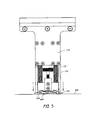
- Figure 5 is a front view of the tool, applicator, and stud from Figure 1 in an actuated position.
- Figure 6 is a front view of the tool from Figure 1 in a released position separated from the applicator and stud.
- Figure 7 is a cross-sectional front view of the tool, applicator, and stud from Figure 1 in the starting position.
- Figure 8 is a cross-sectional side view of the tool, applicator, and stud from Figure 1 in the starting position.
- Figure 9 is a flowchart illustrating a method of applying a stud to a contact surface using the tool from Figure 1 .
- Figure 10 is a functional block diagram of an automatic stud applying machine according to a preferred embodiment of the present invention.
- Figure 1 is a perspective view of a tool 100 for attaching a fastener, such as stud 200, to a contact surface.
- the tool 100 may be operated by a human operator or be incorporated into and controlled by an automatic stud applying machine or other such robotic type device.
- the tool 100 includes an actuating portion 110 and a housing portion 120.
- the actuating portion 110 is slidably connected to the housing portion 120.
- the housing portion 120 is fixedly attached to one or more rods 130 and the housing portion 120 moves vertically along the rods 130, as shown in Figures 4-6 .
- the tool 100 may include one or more springs 132 that are compressed when the tool is actuated to provide a restoring force that returns the tool to a released position.
- the springs 132 surround the rods 130.
- the actuating portion 110 includes means for applying pressure to the anchor feet 312.
- one or more projections 114 as is illustrated in Figure 1 , a pneumatic cylinder, or other means known to a person having ordinary skill in the art which can apply pressure to the anchor feet 312.
- the projections 114 are movable in the vertical direction. As described below with respect to Figures 4-6 , when the tool is actuated, the one or more projections 114 move downward with respect to the housing portion 120 and apply a downward force to the anchor feet 312 of the applicator 300, thereby bending the legs 310 of the applicator 300 towards and into contact with the contact surface 500.
- the projection 114 can be a single projection which contacts both anchor feet 312.
- the projection 114 may have a rectangular cross-sectional shape which circumscribes the outer perimeter of the tool.
- the rectangular shaped projection 114 would contact both anchor feet 312 when moved in the downward direction.
- Figure 1 illustrates an embodiment of the tool 100 that has two projections 114 disposed on opposite sides of the tool 100.
- the two projections 114 move independently of each other.
- the projections 114 may be spring-loaded or otherwise compliant. Such an arrangement provides adequate pressure to adhere the anchor feet 312 when applying the stud 200 and applicator 300 to irregular surfaces having complex curvatures.
- the ends of the anchor feet 312 can pivot to further accommodate irregular surfaces.
- the housing portion 120 is configured to house a stud 200 positioned within an applicator 300.
- Figure 2 is a perspective view of an exemplary applicator 300 and an exemplary stud 200.
- Figure 3 is a partially exploded perspective view of the applicator 300 and stud 200 of Figure 2 .
- the applicator and stud are described in addition detail in U.S. Patent App. No. 13/044,880 , incorporated by reference above and hereby incorporated by reference in its entirety.
- the applicator 300 includes a generally planar body having an inner surface 316 defining a receptacle or opening for receiving at least a portion of the stud 200.
- the applicator includes two or more flexible legs 310 extending away from the body 320.
- Each leg includes an anchor foot 312 at the end of leg 310.
- Each anchor foot is preferably angled relative to its respective leg.
- An adhesive 340 is disposed on each anchor foot 312. In particular, the adhesive 340 covers at least a portion of each anchor foot 312. The adhesive adheres to the contact surface when each anchor foot is in contact with the surface.
- the stud 200 includes a base 220 and a shaft 210 extending from the base 220. At least a portion of the shaft 210 may be threaded.
- the base 220 of the stud 200 may be a composite material.
- the tool 100 is configured to, when actuated, bend each of the legs 310 of the applicator 300 to bring the adhesive 340 disposed thereon in contact with the contact surface.
- the tool 100 is further configured to release the stud 200 and the applicator 300 when the legs 310 of the applicator 300 are thereby attached to the contact surface, as described below with respect to Figures 4-6 .
- the tool may include more or fewer rods.
- the springs 132 are not coaxially located around the rods 130, but positioned elsewhere.
- the tool 100 may include a single spring 132 located between the rods 130.
- the springs 132 are illustrated as compression coils, different biasing devices and other means for applying pressure can be used in other embodiments.
- the tool 100 may include tension/extension springs which are stretched when the tool is actuated to provide a restoring force that returns the tool to a released position.
- the springs 132 can include coil springs, as illustrated, or any mechanical device capable of storing energy.
- the springs 132 may include a pneumatic cylinder.
- Figure 4 is a front view of the tool 100, applicator 300, and stud 200 in a starting position.
- An adhesive 400 is present on a lower surface of the stud 200, having been applied either prior to, or subsequent to, the stud and applicator being inserted into the housing portion 120.
- the adhesive 400 covers a ring shaped portion of the base of the stud 200.
- the adhesive 400 covers the center region of the base of the stud 200.
- the adhesive 400 is an epoxy. After the stud 200 is pressed against the contact surface 500 and the adhesive cures, the adhesive 400 secures the stud 200 to the surface 500.
- the adhesive 400 beneath the stud may have a longer curing time but a greater bonding strength.
- the adhesive 340 disposed on each anchor foot 312 may be high-strength bonding tape or double-side tape and the adhesive 400 beneath the stud may be an epoxy adhesive.
- the tool 100 is positioned to attach the stud 200 to the contact surface 500.
- the projections 114 are vertically aligned over the anchor feet 312 of the applicator 300.
- a downward force is applied to the actuating portion 110 which slides the actuating portion 110 downward along the rods 130, compressing the springs 132.
- the projections 114 also move downward and apply a downward force to the anchor feet 312 of the applicator 300, thereby bending the legs 310 of the applicator 300 toward and into contact with the contact surface 500, as illustrated in Figure 5 .
- Figure 5 is a front view of the tool 100 in an actuated position.
- projections 114 of the actuating portion 110 apply a downward force bending the legs 310 of the applicator 300 such that the anchor feet 312 contact the contact surface 500.
- the adhesive 340 disposed on each anchor foot 312 adheres to the contact surface 500.
- the springs and adhesive(s) are selected such that when the tool is actuated, the projections 114 bend the legs 310 and thereby firmly press the anchor feet 312 and stud 200 into contact with the contact surface 500, but without expelling all of the adhesive 400 from between the feet 312, stud 200 and surface 500.
- the adhesive 340 on the anchor feet 312 may or may not be the same adhesive 400 as is disposed on the base 220 of the stud 200.
- the adhesive 300 on the feet 312 has sufficient tackiness such that shortly after it contacts with the surface 500, each foot 312 is rigidly adhered to the surface, at which time the projections are released and stud 200 and applicator 300 are released from the tool 100, as illustrated in Figure 6 .
- Figure 6 is a front view of the tool 100 in a released position.
- the stud 200 and applicator 300 are detached from the tool 100 and attached to the contact surface 500.
- the adhesive 400 beneath the stud cures, the adhesive 400 secures the stud 200 in place allowing the applicator 300 to be removed without disturbing the stud 200.
- the actuating portion 110 is forced upward by the springs 132 and returned to the same position as in the starting position of Figure 4 . From the released position, another stud 200 and applicator 300 can be inserted into the housing portion 120 and the process of attaching a stud can be performed again.
- the contact surface 500 illustrated in Figures 4-6 is substantially flat, in other embodiments, the contact surface may be concave or convex.
- the actuating portion 110 may slide further along the rods 130 when applying the stud 200 to a convex surface than when applying the stud 200 to a flat surface.
- the contact surface may be irregular such that the applicator 300, when in contact with the contact surface 500, is partially twisted about its horizontal axis. Accordingly, the applicator 300 may be formed of a material flexible enough to at least partially twist about the horizontal axis without breaking.
- Figure 7 is a front cross-sectional view of the tool 100, applicator 300, and stud 200 in the starting position.
- the housing portion 120 is connected to the rods 130.
- the actuating portion 110 includes inner surfaces 116 which define openings through which the rods 130 pass.
- Each rod 130 is fitted with a stop 134 which prevents the actuating portion 110 from separating from the rods 130.
- Figure 7 illustrates gaps between the inner surfaces 116 and the rods 130, it is to be appreciated that embodiments may not include such gaps, or that such gaps may be quite small.
- the stud 200 and applicator 300 are inserted into the housing portion 120 of the tool 100.
- the shaft 210 of the stud 200 is positioned within a receptacle 123 of the housing portion 120 such that a bearing surface 121 of the housing portion contacts the applicator 300.
- the housing portion 120 includes a gripper 122 which grips at least a portion of the stud 200.
- the gripper 122 includes a compressible ring 172 that surrounds the receptacle 123.
- An inner surface of the ring 172 contacts the stud 200.
- the inner surface may or may not be parallel to the gripped portion of the stud 200.
- the inner surface of the compressible ring 172 has a frustoconical shape.
- a screw 175 moves in the vertically downward direction, pushing a plate 176 and a ring 172 in the vertically downward direction until the ring 172 contacts and grips the shaft 210 of the stud 200 within a receptacle 123, thereby holding the stud 200 in place.
- the thumbscrew 174 is turned in the opposite direction, the screw 175, plate 176, and gripping ring 172 move in the vertically upward direction until the ring 172 is detached from the shaft 210 of the stud 200.
- the gripper is an inner surface which provides sufficient friction to grip the shaft 210 when the tool is in the released position, but insufficient friction to grip the shaft 210 when the applicator 300 is adhered to the contact surface 500.
- the gripper is an electromagnet that is controlled by an automatic stud applying machine.
- Figure 8 is a cross-sectional side view of the tool, applicator, and stud from Figure 1 in the starting position.
- the actuating portion 110 includes a front plate 191 and a back plate 192 supporting a handle 112. Supports 194 connect the front plate 191 to the back plate 192.
- the stud 200 and applicator 300 are inserted into the housing portion 120 of the tool 100.
- the shaft 210 of the stud 200 is positioned within a receptacle 123 of the housing portion 120 such that a bearing surface 121 of the housing portion contacts the applicator 300.
- the bearing surface 121 and vertical surfaces 127 define a channel which receives at least a portion of the applicator 300. The channel aligns the applicator 300 with the projections 114, such that, when the tool is actuated, the projections 114 apply a downward force to the anchor feet 312 of the applicator 300, as described above.
- Figure 9 is a flowchart illustrating a method of attaching a stud to a surface.
- the method can be performed by a human operator, or by an automatic stud applying machine or other such robotic type device.
- the method 900 begins, in block 910 with at least a portion of a stud being positioned within an applicator.
- the stud and applicator may be sold or otherwise packaged together such that the stud is prepositioned within the applicator.
- the applicator includes a generally planar body having an inner surface defining a receptacle or opening for receiving at least a portion of the stud.
- the applicator includes two or more flexible legs extending away from the body. Each leg includes an anchor foot at the end of leg.
- Each anchor foot is preferably angled relative to its respective leg.
- An adhesive is disposed on each anchor foot.
- the adhesive covers at least a portion of each anchor foot. The adhesive adheres to the contact surface when each anchor foot is in contact with the surface.
- the stud includes a base and a shaft extending from the base. At least a portion of the shaft may be threaded.
- the stud and applicator are positioned within a tool, such as the tool of Figure 1 .
- the tool may include a housing portion in which the stud and applicator are positioned and an actuating portion slidably connected to the housing portion.
- positioning the stud and applicator within the tool includes actuating a gripper of the tool to retain the stud and application within the tool.
- adhesive is applied to the stud.
- the adhesive is an epoxy and is applied in a ring on the base of the stud.
- the adhesive is applied prior to positioning the stud within the tool.
- the step described with respect to block 930 may be performed prior to the step described with respect to block 920.
- the adhesive may be sold or otherwise packaged with adhesive pre-applied to the stud.
- the steps described with respect to block 910 and/or 930 may not be performed.
- the tool is moved such that the stud is positioned against a surface.
- the surface is not flat.
- the surface may be concave or convex, or have a complex curvature.
- the tool is actuated by sliding the actuating portion with respect to the housing portion, thereby bending two or more legs of the applicator towards the surface until an adhesive layer on the legs contacts the surface.
- the stud and applicator are released from the tool.
- the stud and applicator may be released by deactuating a gripper of the tool.
- the stud and applicator may be released simply by removing the tool, leaving the stud and applicator attached to the surface.
- the method 900 pauses in block 970 until the applied adhesive is sufficiently cured.
- the applicator is removed, leaving the stud bonded to the surface by the cured adhesive.
- the method 900 can be repeated, by returning to block 910, for attaching additional studs to the surface.
- FIG. 10 is a functional block diagram of an automatic stud applying machine 1000.
- the automatic stud applying machine 1000 includes a processor 1010 in data communication with a memory 1020, and a tool 1030.
- the processor 1010 may control a positioning system 1032, an actuator 1034, and a gripper 1036.
- the processor 1010 can be a general purpose processor, a digital signal processor (DSP), an application specific integrated circuit (ASIC), a field programmable gate array (FPGA) or other programmable logic device, discrete gate or transistor logic, discrete hardware components, or any suitable combination thereof designed to perform the functions described herein.
- a processor may also be implemented as a combination of computing devices, e.g., a combination of a DSP and a microprocessor, a plurality of microprocessors, one or more microprocessors in conjunction with a DSP core, or any other such configuration.
- the processor 1010 can be coupled, via one or more buses, to read information from or write information to the memory 1020.
- the processor may additionally, or in the alternative, contain memory, such as processor registers.
- the memory 1020 can include processor cache, including a multi-level hierarchical cache in which different levels have different capacities and access speeds.
- the memory 1020 can also include random access memory (RAM), other volatile storage devices, or nonvolatile storage devices.
- the storage can include storage devices including hard drives, optical discs, such as compact discs (CDs) or digital video discs (DVDs), flash memory, floppy discs, magnetic tape, and Zip drives.
- the memory 1020 may store processor-executable instructions for operating the tool and for applying studs to a surface.
- the processor 1010 is coupled to the tool 1030 and is configured to control operation of the tool 1030. In controlling the tool 1030, the processor may receive information from one or more sensors regarding the state or position of the tool 1030 or portions thereof.
- the processor 1010 controls the positioning system 1032 to position a stud within the tool or to position the stud against a surface in a predetermined position.
- the positioning system 1032 may include one or more motors.
- the positioning system 1032 may include a robotic arm.
- the processor 1010 can control the actuator 1034 to move the tool from a starting position to an actuated position and to a released position as described above with respect to Figures 4-6 .
- the processor 1010 can control the actuator 1034 to move a slidably connected portion of the tool 1030 with respect to a fixed portion of the tool 1030.
- the actuator 1034 may include, for example, a motor or a piston.
- the processor 1010 can control the gripper 1036 to grip or release the stud from with the tool 1030.
- the gripper 1036 includes a compressible ring as described above with respect to Figure 7 .
- the gripper 1036 may include a motor.
- the gripper 1036 is an electromagnet or other such electronically controlled gripping device.
Landscapes
- Engineering & Computer Science (AREA)
- Mechanical Engineering (AREA)
- Insertion Pins And Rivets (AREA)
- Hand Tools For Fitting Together And Separating, Or Other Hand Tools (AREA)
- Snaps, Bayonet Connections, Set Pins, And Snap Rings (AREA)
- Coating Apparatus (AREA)
Applications Claiming Priority (1)
| Application Number | Priority Date | Filing Date | Title |
|---|---|---|---|
| US13/044,862 US8756779B2 (en) | 2011-03-10 | 2011-03-10 | Tool for attaching a stud to a surface |
Publications (3)
| Publication Number | Publication Date |
|---|---|
| EP2497603A2 true EP2497603A2 (fr) | 2012-09-12 |
| EP2497603A3 EP2497603A3 (fr) | 2016-04-27 |
| EP2497603B1 EP2497603B1 (fr) | 2018-05-30 |
Family
ID=45808365
Family Applications (1)
| Application Number | Title | Priority Date | Filing Date |
|---|---|---|---|
| EP12250036.6A Active EP2497603B1 (fr) | 2011-03-10 | 2012-02-21 | Outil de fixation d'un goujon sur une surface |
Country Status (3)
| Country | Link |
|---|---|
| US (1) | US8756779B2 (fr) |
| EP (1) | EP2497603B1 (fr) |
| CA (1) | CA2768276A1 (fr) |
Families Citing this family (1)
| Publication number | Priority date | Publication date | Assignee | Title |
|---|---|---|---|---|
| CN112720349B (zh) * | 2020-12-11 | 2023-04-11 | 山西江淮重工有限责任公司 | 双头螺柱的装卸装置及装卸双头螺柱的方法 |
Family Cites Families (7)
| Publication number | Priority date | Publication date | Assignee | Title |
|---|---|---|---|---|
| US4778702A (en) | 1985-09-04 | 1988-10-18 | Physical Systems, Inc. | Adhesive attachment and mounting fixture |
| US4842912A (en) | 1985-09-04 | 1989-06-27 | Physical Systems, Inc. | Adhesive attachment and mounting fixture |
| US4822656A (en) | 1985-09-04 | 1989-04-18 | Physical Systems, Inc. | Fixture for securing an adhesive attachment to a substrate |
| US4668546A (en) | 1985-09-04 | 1987-05-26 | Physical Systems, Inc. | Fixture for securing an adhesive attachment to a substrate |
| DE29917498U1 (de) * | 1999-10-05 | 2000-01-05 | Schüco International KG, 33609 Bielefeld | Montagehalter für eine durch einen Kleber festlegbare Leiste |
| WO2006007357A2 (fr) * | 2004-06-21 | 2006-01-19 | Physical Systems, Inc. | Fixation adhesive avec mise electrique a la terre |
| US7584582B1 (en) | 2006-02-14 | 2009-09-08 | Physical Systems, Inc. | Adhesive bonded attachment assembly for an insulation blanket |
-
2011
- 2011-03-10 US US13/044,862 patent/US8756779B2/en active Active
-
2012
- 2012-02-16 CA CA2768276A patent/CA2768276A1/fr not_active Abandoned
- 2012-02-21 EP EP12250036.6A patent/EP2497603B1/fr active Active
Also Published As
| Publication number | Publication date |
|---|---|
| US20120227244A1 (en) | 2012-09-13 |
| US8756779B2 (en) | 2014-06-24 |
| EP2497603A3 (fr) | 2016-04-27 |
| CA2768276A1 (fr) | 2012-09-10 |
| EP2497603B1 (fr) | 2018-05-30 |
Similar Documents
| Publication | Publication Date | Title |
|---|---|---|
| US7954794B2 (en) | Assembly method and apparatus | |
| EP1733888A3 (fr) | Dispositif pour le montage/démontage d'une cartouche à encre, dispositif d'enregistrement et appareil pour l'éjection de liquide | |
| US20120240690A1 (en) | Binding force testing device | |
| CN107498304A (zh) | 弹簧夹组装机及其工作方法 | |
| US9417718B2 (en) | Input apparatus with force feedback | |
| US8464991B2 (en) | Fixing device for planar display panel | |
| US20090250421A1 (en) | Fixing seat for rail of modem/servo carrying and stowing rack | |
| EP1881234A3 (fr) | Dispositif de forçage pour un levier mobile | |
| US8756779B2 (en) | Tool for attaching a stud to a surface | |
| CN102259312B (zh) | 定位装置 | |
| JP5860908B2 (ja) | ワーク把持装置 | |
| EP2497604B1 (fr) | Système et procédé de fixation d'un goujon sur une surface | |
| US10987913B2 (en) | Pad removal device and method | |
| EP1975105A3 (fr) | Dispositif d'application de tension | |
| JP2010521574A5 (fr) | ||
| CN108381455B (zh) | 一种安装方法 | |
| US20120103053A1 (en) | Apparatus for bending resilient tab | |
| CN113275871B (zh) | 一种弹簧卡箍装配装置 | |
| US11738443B2 (en) | Socket-locker | |
| US20110011680A1 (en) | Lubricant applicator for golden finger interface | |
| CN219139569U (zh) | 点胶组接用的保压装置及组装设备 | |
| JP2021020300A (ja) | 試験管把持装置、及び試験管把持方法 | |
| US10919253B2 (en) | Quilling device | |
| CN222538751U (zh) | 物品夹持机构 | |
| JP7839627B2 (ja) | 材料試験のための装置及び方法 |
Legal Events
| Date | Code | Title | Description |
|---|---|---|---|
| PUAI | Public reference made under article 153(3) epc to a published international application that has entered the european phase |
Free format text: ORIGINAL CODE: 0009012 |
|
| 17P | Request for examination filed |
Effective date: 20120306 |
|
| AK | Designated contracting states |
Kind code of ref document: A2 Designated state(s): AL AT BE BG CH CY CZ DE DK EE ES FI FR GB GR HR HU IE IS IT LI LT LU LV MC MK MT NL NO PL PT RO RS SE SI SK SM TR |
|
| AX | Request for extension of the european patent |
Extension state: BA ME |
|
| PUAL | Search report despatched |
Free format text: ORIGINAL CODE: 0009013 |
|
| AK | Designated contracting states |
Kind code of ref document: A3 Designated state(s): AL AT BE BG CH CY CZ DE DK EE ES FI FR GB GR HR HU IE IS IT LI LT LU LV MC MK MT NL NO PL PT RO RS SE SI SK SM TR |
|
| AX | Request for extension of the european patent |
Extension state: BA ME |
|
| RIC1 | Information provided on ipc code assigned before grant |
Ipc: B25B 31/00 20060101ALI20160322BHEP Ipc: B25B 5/06 20060101AFI20160322BHEP |
|
| GRAP | Despatch of communication of intention to grant a patent |
Free format text: ORIGINAL CODE: EPIDOSNIGR1 |
|
| STAA | Information on the status of an ep patent application or granted ep patent |
Free format text: STATUS: GRANT OF PATENT IS INTENDED |
|
| INTG | Intention to grant announced |
Effective date: 20171208 |
|
| GRAS | Grant fee paid |
Free format text: ORIGINAL CODE: EPIDOSNIGR3 |
|
| GRAA | (expected) grant |
Free format text: ORIGINAL CODE: 0009210 |
|
| STAA | Information on the status of an ep patent application or granted ep patent |
Free format text: STATUS: THE PATENT HAS BEEN GRANTED |
|
| AK | Designated contracting states |
Kind code of ref document: B1 Designated state(s): AL AT BE BG CH CY CZ DE DK EE ES FI FR GB GR HR HU IE IS IT LI LT LU LV MC MK MT NL NO PL PT RO RS SE SI SK SM TR |
|
| REG | Reference to a national code |
Ref country code: GB Ref legal event code: FG4D |
|
| REG | Reference to a national code |
Ref country code: CH Ref legal event code: EP |
|
| REG | Reference to a national code |
Ref country code: AT Ref legal event code: REF Ref document number: 1003130 Country of ref document: AT Kind code of ref document: T Effective date: 20180615 |
|
| REG | Reference to a national code |
Ref country code: IE Ref legal event code: FG4D |
|
| REG | Reference to a national code |
Ref country code: DE Ref legal event code: R096 Ref document number: 602012046838 Country of ref document: DE |
|
| REG | Reference to a national code |
Ref country code: NL Ref legal event code: MP Effective date: 20180530 |
|
| REG | Reference to a national code |
Ref country code: LT Ref legal event code: MG4D |
|
| PG25 | Lapsed in a contracting state [announced via postgrant information from national office to epo] |
Ref country code: BG Free format text: LAPSE BECAUSE OF FAILURE TO SUBMIT A TRANSLATION OF THE DESCRIPTION OR TO PAY THE FEE WITHIN THE PRESCRIBED TIME-LIMIT Effective date: 20180830 Ref country code: FI Free format text: LAPSE BECAUSE OF FAILURE TO SUBMIT A TRANSLATION OF THE DESCRIPTION OR TO PAY THE FEE WITHIN THE PRESCRIBED TIME-LIMIT Effective date: 20180530 Ref country code: NO Free format text: LAPSE BECAUSE OF FAILURE TO SUBMIT A TRANSLATION OF THE DESCRIPTION OR TO PAY THE FEE WITHIN THE PRESCRIBED TIME-LIMIT Effective date: 20180830 Ref country code: LT Free format text: LAPSE BECAUSE OF FAILURE TO SUBMIT A TRANSLATION OF THE DESCRIPTION OR TO PAY THE FEE WITHIN THE PRESCRIBED TIME-LIMIT Effective date: 20180530 Ref country code: ES Free format text: LAPSE BECAUSE OF FAILURE TO SUBMIT A TRANSLATION OF THE DESCRIPTION OR TO PAY THE FEE WITHIN THE PRESCRIBED TIME-LIMIT Effective date: 20180530 Ref country code: SE Free format text: LAPSE BECAUSE OF FAILURE TO SUBMIT A TRANSLATION OF THE DESCRIPTION OR TO PAY THE FEE WITHIN THE PRESCRIBED TIME-LIMIT Effective date: 20180530 Ref country code: CY Free format text: LAPSE BECAUSE OF FAILURE TO SUBMIT A TRANSLATION OF THE DESCRIPTION OR TO PAY THE FEE WITHIN THE PRESCRIBED TIME-LIMIT Effective date: 20180530 |
|
| PG25 | Lapsed in a contracting state [announced via postgrant information from national office to epo] |
Ref country code: LV Free format text: LAPSE BECAUSE OF FAILURE TO SUBMIT A TRANSLATION OF THE DESCRIPTION OR TO PAY THE FEE WITHIN THE PRESCRIBED TIME-LIMIT Effective date: 20180530 Ref country code: RS Free format text: LAPSE BECAUSE OF FAILURE TO SUBMIT A TRANSLATION OF THE DESCRIPTION OR TO PAY THE FEE WITHIN THE PRESCRIBED TIME-LIMIT Effective date: 20180530 Ref country code: GR Free format text: LAPSE BECAUSE OF FAILURE TO SUBMIT A TRANSLATION OF THE DESCRIPTION OR TO PAY THE FEE WITHIN THE PRESCRIBED TIME-LIMIT Effective date: 20180831 Ref country code: HR Free format text: LAPSE BECAUSE OF FAILURE TO SUBMIT A TRANSLATION OF THE DESCRIPTION OR TO PAY THE FEE WITHIN THE PRESCRIBED TIME-LIMIT Effective date: 20180530 |
|
| REG | Reference to a national code |
Ref country code: AT Ref legal event code: MK05 Ref document number: 1003130 Country of ref document: AT Kind code of ref document: T Effective date: 20180530 |
|
| PG25 | Lapsed in a contracting state [announced via postgrant information from national office to epo] |
Ref country code: NL Free format text: LAPSE BECAUSE OF FAILURE TO SUBMIT A TRANSLATION OF THE DESCRIPTION OR TO PAY THE FEE WITHIN THE PRESCRIBED TIME-LIMIT Effective date: 20180530 |
|
| PG25 | Lapsed in a contracting state [announced via postgrant information from national office to epo] |
Ref country code: EE Free format text: LAPSE BECAUSE OF FAILURE TO SUBMIT A TRANSLATION OF THE DESCRIPTION OR TO PAY THE FEE WITHIN THE PRESCRIBED TIME-LIMIT Effective date: 20180530 Ref country code: DK Free format text: LAPSE BECAUSE OF FAILURE TO SUBMIT A TRANSLATION OF THE DESCRIPTION OR TO PAY THE FEE WITHIN THE PRESCRIBED TIME-LIMIT Effective date: 20180530 Ref country code: AT Free format text: LAPSE BECAUSE OF FAILURE TO SUBMIT A TRANSLATION OF THE DESCRIPTION OR TO PAY THE FEE WITHIN THE PRESCRIBED TIME-LIMIT Effective date: 20180530 Ref country code: PL Free format text: LAPSE BECAUSE OF FAILURE TO SUBMIT A TRANSLATION OF THE DESCRIPTION OR TO PAY THE FEE WITHIN THE PRESCRIBED TIME-LIMIT Effective date: 20180530 Ref country code: SK Free format text: LAPSE BECAUSE OF FAILURE TO SUBMIT A TRANSLATION OF THE DESCRIPTION OR TO PAY THE FEE WITHIN THE PRESCRIBED TIME-LIMIT Effective date: 20180530 Ref country code: RO Free format text: LAPSE BECAUSE OF FAILURE TO SUBMIT A TRANSLATION OF THE DESCRIPTION OR TO PAY THE FEE WITHIN THE PRESCRIBED TIME-LIMIT Effective date: 20180530 Ref country code: CZ Free format text: LAPSE BECAUSE OF FAILURE TO SUBMIT A TRANSLATION OF THE DESCRIPTION OR TO PAY THE FEE WITHIN THE PRESCRIBED TIME-LIMIT Effective date: 20180530 |
|
| PG25 | Lapsed in a contracting state [announced via postgrant information from national office to epo] |
Ref country code: IT Free format text: LAPSE BECAUSE OF FAILURE TO SUBMIT A TRANSLATION OF THE DESCRIPTION OR TO PAY THE FEE WITHIN THE PRESCRIBED TIME-LIMIT Effective date: 20180530 Ref country code: SM Free format text: LAPSE BECAUSE OF FAILURE TO SUBMIT A TRANSLATION OF THE DESCRIPTION OR TO PAY THE FEE WITHIN THE PRESCRIBED TIME-LIMIT Effective date: 20180530 |
|
| REG | Reference to a national code |
Ref country code: DE Ref legal event code: R097 Ref document number: 602012046838 Country of ref document: DE |
|
| PLBE | No opposition filed within time limit |
Free format text: ORIGINAL CODE: 0009261 |
|
| STAA | Information on the status of an ep patent application or granted ep patent |
Free format text: STATUS: NO OPPOSITION FILED WITHIN TIME LIMIT |
|
| 26N | No opposition filed |
Effective date: 20190301 |
|
| PG25 | Lapsed in a contracting state [announced via postgrant information from national office to epo] |
Ref country code: SI Free format text: LAPSE BECAUSE OF FAILURE TO SUBMIT A TRANSLATION OF THE DESCRIPTION OR TO PAY THE FEE WITHIN THE PRESCRIBED TIME-LIMIT Effective date: 20180530 |
|
| REG | Reference to a national code |
Ref country code: CH Ref legal event code: PL |
|
| PG25 | Lapsed in a contracting state [announced via postgrant information from national office to epo] |
Ref country code: LU Free format text: LAPSE BECAUSE OF NON-PAYMENT OF DUE FEES Effective date: 20190221 Ref country code: MC Free format text: LAPSE BECAUSE OF FAILURE TO SUBMIT A TRANSLATION OF THE DESCRIPTION OR TO PAY THE FEE WITHIN THE PRESCRIBED TIME-LIMIT Effective date: 20180530 |
|
| REG | Reference to a national code |
Ref country code: BE Ref legal event code: MM Effective date: 20190228 |
|
| REG | Reference to a national code |
Ref country code: IE Ref legal event code: MM4A |
|
| PG25 | Lapsed in a contracting state [announced via postgrant information from national office to epo] |
Ref country code: AL Free format text: LAPSE BECAUSE OF FAILURE TO SUBMIT A TRANSLATION OF THE DESCRIPTION OR TO PAY THE FEE WITHIN THE PRESCRIBED TIME-LIMIT Effective date: 20180530 |
|
| PG25 | Lapsed in a contracting state [announced via postgrant information from national office to epo] |
Ref country code: CH Free format text: LAPSE BECAUSE OF NON-PAYMENT OF DUE FEES Effective date: 20190228 Ref country code: LI Free format text: LAPSE BECAUSE OF NON-PAYMENT OF DUE FEES Effective date: 20190228 |
|
| PG25 | Lapsed in a contracting state [announced via postgrant information from national office to epo] |
Ref country code: IE Free format text: LAPSE BECAUSE OF NON-PAYMENT OF DUE FEES Effective date: 20190221 |
|
| PG25 | Lapsed in a contracting state [announced via postgrant information from national office to epo] |
Ref country code: BE Free format text: LAPSE BECAUSE OF NON-PAYMENT OF DUE FEES Effective date: 20190228 |
|
| PG25 | Lapsed in a contracting state [announced via postgrant information from national office to epo] |
Ref country code: TR Free format text: LAPSE BECAUSE OF FAILURE TO SUBMIT A TRANSLATION OF THE DESCRIPTION OR TO PAY THE FEE WITHIN THE PRESCRIBED TIME-LIMIT Effective date: 20180530 |
|
| PG25 | Lapsed in a contracting state [announced via postgrant information from national office to epo] |
Ref country code: PT Free format text: LAPSE BECAUSE OF FAILURE TO SUBMIT A TRANSLATION OF THE DESCRIPTION OR TO PAY THE FEE WITHIN THE PRESCRIBED TIME-LIMIT Effective date: 20181001 Ref country code: MT Free format text: LAPSE BECAUSE OF NON-PAYMENT OF DUE FEES Effective date: 20190221 |
|
| PG25 | Lapsed in a contracting state [announced via postgrant information from national office to epo] |
Ref country code: IS Free format text: LAPSE BECAUSE OF FAILURE TO SUBMIT A TRANSLATION OF THE DESCRIPTION OR TO PAY THE FEE WITHIN THE PRESCRIBED TIME-LIMIT Effective date: 20180930 |
|
| PG25 | Lapsed in a contracting state [announced via postgrant information from national office to epo] |
Ref country code: HU Free format text: LAPSE BECAUSE OF FAILURE TO SUBMIT A TRANSLATION OF THE DESCRIPTION OR TO PAY THE FEE WITHIN THE PRESCRIBED TIME-LIMIT; INVALID AB INITIO Effective date: 20120221 |
|
| PG25 | Lapsed in a contracting state [announced via postgrant information from national office to epo] |
Ref country code: MK Free format text: LAPSE BECAUSE OF FAILURE TO SUBMIT A TRANSLATION OF THE DESCRIPTION OR TO PAY THE FEE WITHIN THE PRESCRIBED TIME-LIMIT Effective date: 20180530 |
|
| P01 | Opt-out of the competence of the unified patent court (upc) registered |
Free format text: CASE NUMBER: UPC_APP_0016490_2497603/2025 Effective date: 20251209 |
|
| PGFP | Annual fee paid to national office [announced via postgrant information from national office to epo] |
Ref country code: GB Payment date: 20260121 Year of fee payment: 15 |
|
| PGFP | Annual fee paid to national office [announced via postgrant information from national office to epo] |
Ref country code: DE Payment date: 20260121 Year of fee payment: 15 |
|
| PGFP | Annual fee paid to national office [announced via postgrant information from national office to epo] |
Ref country code: FR Payment date: 20260121 Year of fee payment: 15 |