EP2497623B1 - Gabarit pour la fabrication d'une structure en matériau composite - Google Patents
Gabarit pour la fabrication d'une structure en matériau composite Download PDFInfo
- Publication number
- EP2497623B1 EP2497623B1 EP10828085.0A EP10828085A EP2497623B1 EP 2497623 B1 EP2497623 B1 EP 2497623B1 EP 10828085 A EP10828085 A EP 10828085A EP 2497623 B1 EP2497623 B1 EP 2497623B1
- Authority
- EP
- European Patent Office
- Prior art keywords
- insertion portion
- bladder
- band
- metal member
- terminal metal
- Prior art date
- Legal status (The legal status is an assumption and is not a legal conclusion. Google has not performed a legal analysis and makes no representation as to the accuracy of the status listed.)
- Active
Links
Images





Classifications
-
- B—PERFORMING OPERATIONS; TRANSPORTING
- B29—WORKING OF PLASTICS; WORKING OF SUBSTANCES IN A PLASTIC STATE IN GENERAL
- B29C—SHAPING OR JOINING OF PLASTICS; SHAPING OF MATERIAL IN A PLASTIC STATE, NOT OTHERWISE PROVIDED FOR; AFTER-TREATMENT OF THE SHAPED PRODUCTS, e.g. REPAIRING
- B29C70/00—Shaping composites, i.e. plastics material comprising reinforcements, fillers or preformed parts, e.g. inserts
- B29C70/04—Shaping composites, i.e. plastics material comprising reinforcements, fillers or preformed parts, e.g. inserts comprising reinforcements only, e.g. self-reinforcing plastics
- B29C70/28—Shaping operations therefor
- B29C70/40—Shaping or impregnating by compression not applied
- B29C70/42—Shaping or impregnating by compression not applied for producing articles of definite length, i.e. discrete articles
- B29C70/44—Shaping or impregnating by compression not applied for producing articles of definite length, i.e. discrete articles using isostatic pressure, e.g. pressure difference-moulding, vacuum bag-moulding, autoclave-moulding or expanding rubber-moulding
- B29C70/446—Moulding structures having an axis of symmetry or at least one channel, e.g. tubular structures, frames
-
- B—PERFORMING OPERATIONS; TRANSPORTING
- B29—WORKING OF PLASTICS; WORKING OF SUBSTANCES IN A PLASTIC STATE IN GENERAL
- B29C—SHAPING OR JOINING OF PLASTICS; SHAPING OF MATERIAL IN A PLASTIC STATE, NOT OTHERWISE PROVIDED FOR; AFTER-TREATMENT OF THE SHAPED PRODUCTS, e.g. REPAIRING
- B29C33/00—Moulds or cores; Details thereof or accessories therefor
- B29C33/44—Moulds or cores; Details thereof or accessories therefor with means for, or specially constructed to facilitate, the removal of articles, e.g. of undercut articles
- B29C33/48—Moulds or cores; Details thereof or accessories therefor with means for, or specially constructed to facilitate, the removal of articles, e.g. of undercut articles with means for collapsing or disassembling
- B29C33/50—Moulds or cores; Details thereof or accessories therefor with means for, or specially constructed to facilitate, the removal of articles, e.g. of undercut articles with means for collapsing or disassembling elastic or flexible
- B29C33/505—Moulds or cores; Details thereof or accessories therefor with means for, or specially constructed to facilitate, the removal of articles, e.g. of undercut articles with means for collapsing or disassembling elastic or flexible cores or mandrels, e.g. inflatable
-
- B—PERFORMING OPERATIONS; TRANSPORTING
- B29—WORKING OF PLASTICS; WORKING OF SUBSTANCES IN A PLASTIC STATE IN GENERAL
- B29C—SHAPING OR JOINING OF PLASTICS; SHAPING OF MATERIAL IN A PLASTIC STATE, NOT OTHERWISE PROVIDED FOR; AFTER-TREATMENT OF THE SHAPED PRODUCTS, e.g. REPAIRING
- B29C43/00—Compression moulding, i.e. applying external pressure to flow the moulding material; Apparatus therefor
- B29C43/02—Compression moulding, i.e. applying external pressure to flow the moulding material; Apparatus therefor of articles of definite length, i.e. discrete articles
- B29C43/10—Isostatic pressing, i.e. using non-rigid pressure-exerting members against rigid parts or dies
- B29C43/12—Isostatic pressing, i.e. using non-rigid pressure-exerting members against rigid parts or dies using bags surrounding the moulding material or using membranes contacting the moulding material
-
- B—PERFORMING OPERATIONS; TRANSPORTING
- B29—WORKING OF PLASTICS; WORKING OF SUBSTANCES IN A PLASTIC STATE IN GENERAL
- B29C—SHAPING OR JOINING OF PLASTICS; SHAPING OF MATERIAL IN A PLASTIC STATE, NOT OTHERWISE PROVIDED FOR; AFTER-TREATMENT OF THE SHAPED PRODUCTS, e.g. REPAIRING
- B29C43/00—Compression moulding, i.e. applying external pressure to flow the moulding material; Apparatus therefor
- B29C43/32—Component parts, details or accessories; Auxiliary operations
- B29C43/36—Moulds for making articles of definite length, i.e. discrete articles
- B29C43/3642—Bags, bleeder sheets or cauls for isostatic pressing
-
- B—PERFORMING OPERATIONS; TRANSPORTING
- B29—WORKING OF PLASTICS; WORKING OF SUBSTANCES IN A PLASTIC STATE IN GENERAL
- B29D—PRODUCING PARTICULAR ARTICLES FROM PLASTICS OR FROM SUBSTANCES IN A PLASTIC STATE
- B29D99/00—Subject matter not provided for in other groups of this subclass
- B29D99/001—Producing wall or panel-like structures, e.g. for hulls, fuselages, or buildings
- B29D99/0014—Producing wall or panel-like structures, e.g. for hulls, fuselages, or buildings provided with ridges or ribs, e.g. joined ribs
-
- B—PERFORMING OPERATIONS; TRANSPORTING
- B29—WORKING OF PLASTICS; WORKING OF SUBSTANCES IN A PLASTIC STATE IN GENERAL
- B29C—SHAPING OR JOINING OF PLASTICS; SHAPING OF MATERIAL IN A PLASTIC STATE, NOT OTHERWISE PROVIDED FOR; AFTER-TREATMENT OF THE SHAPED PRODUCTS, e.g. REPAIRING
- B29C43/00—Compression moulding, i.e. applying external pressure to flow the moulding material; Apparatus therefor
- B29C43/32—Component parts, details or accessories; Auxiliary operations
- B29C43/36—Moulds for making articles of definite length, i.e. discrete articles
- B29C43/3642—Bags, bleeder sheets or cauls for isostatic pressing
- B29C2043/3649—Inflatable bladders using gas or fluid and related details
-
- B—PERFORMING OPERATIONS; TRANSPORTING
- B64—AIRCRAFT; AVIATION; COSMONAUTICS
- B64F—GROUND OR AIRCRAFT-CARRIER-DECK INSTALLATIONS SPECIALLY ADAPTED FOR USE IN CONNECTION WITH AIRCRAFT; DESIGNING, MANUFACTURING, ASSEMBLING, CLEANING, MAINTAINING OR REPAIRING AIRCRAFT, NOT OTHERWISE PROVIDED FOR; HANDLING, TRANSPORTING, TESTING OR INSPECTING AIRCRAFT COMPONENTS, NOT OTHERWISE PROVIDED FOR
- B64F5/00—Designing, manufacturing, assembling, cleaning, maintaining or repairing aircraft, not otherwise provided for; Handling, transporting, testing or inspecting aircraft components, not otherwise provided for
- B64F5/10—Manufacturing or assembling aircraft, e.g. jigs therefor
-
- Y—GENERAL TAGGING OF NEW TECHNOLOGICAL DEVELOPMENTS; GENERAL TAGGING OF CROSS-SECTIONAL TECHNOLOGIES SPANNING OVER SEVERAL SECTIONS OF THE IPC; TECHNICAL SUBJECTS COVERED BY FORMER USPC CROSS-REFERENCE ART COLLECTIONS [XRACs] AND DIGESTS
- Y02—TECHNOLOGIES OR APPLICATIONS FOR MITIGATION OR ADAPTATION AGAINST CLIMATE CHANGE
- Y02T—CLIMATE CHANGE MITIGATION TECHNOLOGIES RELATED TO TRANSPORTATION
- Y02T50/00—Aeronautics or air transport
- Y02T50/40—Weight reduction
Definitions
- the present invention relates to a jig for use in manufacturing a composite material structure using a fiber-reinforced resin composite material according to the preamble of claim 1, see for example disclosure of US6143236A .
- the present invention relates to an inflatable bag-shaped jig (bladder) for use as a jig of a hat (hat-shaped) stringer in manufacturing a structure using the hat stringer as a frame member.
- composite materials fiber-reinforced resin composite materials
- metal materials have been used so far.
- composite materials carbon-fiber-reinforced materials which are formed such that carbon fibers used as reinforced fibers, are impregnated with matrix resin such as epoxy resin, have a smaller weight and a higher strength than metal materials. Because of this, the carbon-fiber-reinforced materials are widely used in fields of sport activity articles, industrial machines, and aerospace.
- a stiffened panel in which a skin comprising a composite material is integrated with a stiffener which is a lightweight metal frame member has been used.
- a typical stiffener there are a stringer and a frame.
- the stringer is a member having a relatively small thickness and is placed to extend in a lengthwise direction of the structure.
- the frame is a member having a relatively great thickness and is placed to cross the stringer in a direction (direction perpendicular to the lengthwise direction) of the transverse cross-section of the structure.
- the stringers are supported by jigs and arranged to conform to the shape of the structure.
- Plural sheets of prepreg are stacked together with the stringers, and the resulting stack is pressurized and heated in an autoclave. As a result, the prepreg is cured into skin, and the stringers are adhesively attached to and integrated with the skin. Further, the frame is attached to the stringers, thereby forming a stiffened panel.
- the aircraft is required to minimize its weight, but is required to have a sufficient strength. Because of this, a thickness of the skin which is a body of the stiffened panel cannot be set constant, but is set greater in a region required to have a higher strength and smaller in a region which can provide a sufficient strength, thereby achieving a reduced weight.
- the jig supporting the stringer is an elongated member extending along the stringer, and defines a positional relationship between the prepreg and the stringer. The jig is drawn out along its lengthwise direction after the prepreg is cured. Because of this, if the skin has a uniform thickness, a surface of the skin which contacts the stringer is flat.
- the hat stringer has a pair of flat band-shaped portions extending in a lengthwise direction of the stringer, and a channel portion having a transverse cross-section recessed in a trapezoidal shape between the band-shaped portions.
- the band-shaped portions are surfaces (adhesion surfaces) adhesively attached to the inner surface of the skin.
- the hat stringers are placed along the lengthwise direction of the body with the adhesion surfaces being at an outer side, and the frame is placed in a circumferential direction of the body, thereby forming an assembly having a predetermined structure, for example, a cylindrical structure.
- the prepreg is wound around outside of the cylindrical structure and stacked thereon.
- a jig such as a mandrel is attached to the interior of the cylindrical structure.
- a jig such as a mandrel is attached to the interior of the cylindrical structure.
- an elongated jig called a bladder is inserted in a space formed between the skin and each of the hat stringers, i.e., inner side of the channel portion.
- the bladder is made of a material having flexibility and elasticity (stretchability).
- the bladder is inflatable (expandable) and contractible and has a structure of an elongated bag-shape.
- an internal pressure is increased to allow the bladder to be inflated (expanded).
- the bladder maintains a state where the prepreg is stretched under tension to prevent the prepreg from being deformed between the band-shaped portions.
- the internal pressure is lowered, and the bladder is contracted and drawn out of the channel portion.
- the band-shaped portions of the stringer are adhesively attached to and integrated with the inner surface of the skin.
- the bladder has changed its state from the inflated state to the contacted state to have a smaller cross-section and has a flexibility, and therefore, the bladder can be easily drawn out of the channel portion without being affected by the unevenness.
- the bladder has a function similar to that of an inflatable mandrel.
- An exemplary inflatable mandrel has a configuration in which the mandrel is composed of plural layers and has a cylindrical bag shape inflatable and contractible, as disclosed in Patent Literature 1.
- the mandrel is inflated and serves as an inner mold (core) with respect to an outer mold.
- the mandrel is easily inserted into a cavity of the outer mold, and is easily drawn out of a molded drum-shaped object.
- Patent Literature 2 discloses a manufacturing technique of a racket using the inflatable mandrel
- Patent Literature 3 discloses a technique for manufacturing a spar of a rotary wing aircraft using the inflatable mandrel.
- the general bladder has a configuration in which a terminal metal member which is a metal-made sealing member and has a pressurization hole for pressurizing the interior of a pipe-shaped body is attached to one end portion of the pipe-shaped body and a terminal plug which is a sealing member made of an elastic material is attached to the other end portion.
- the bladder having the terminal metal member has a problem which is not assumed in the general inflatable mandrel.
- the bladder serves as a "backing member" of the prepreg. Since the terminal metal member has the pressurization hole, the terminal metal member is not covered with the prepreg but is exposed in the channel portion in a state where the bladder is inserted into the channel portion of the hat stringer. This is because of the fact that when the hat stringer and the bladder are introduced into the autoclave and heated and pressurized therein, a pressurized atmosphere is transmitted to the interior of the body through the pressurization hole. Therefore, when the bladder is drawn out of the channel portion after treatment in the autoclave, the terminal metal member is dragged to outside.
- the present invention is directed to solving the above mentioned problem, and an object of the present invention is to provide a bladder-type jig which is suitably used to manufacture a stiffened panel structure using a hat stringer, among composite material structures, and can implement durability which enables repeated use.
- a jig used for manufacturing a composite material structure the jig being inserted into a channel portion of a hat stringer and used, when the composite material structure is manufactured by attaching prepreg to a frame structure including the hat stringer as a frame member, the channel portion extending in a lengthwise direction of the hat stringer;
- the jig comprising: a body having a pipe shape and made of an elastic material, the body having a transverse cross-section of a trapezoidal shape which is a cross-section perpendicular to a lengthwise direction of the body; and a terminal metal member attached to one end portion of the body and having a pressurization hole for pressurizing an interior of the body; wherein the terminal metal member has an insertion portion inserted into a hollow space of the body; the insertion portion has a columnar shape having a transverse cross-section conforming in shape to a contour shape of the hollow space of the body; the insertion portion is provided on an outer peripheral
- the band-shaped groove portion provided on the insertion portion forms a space in which an adhesive is filled, and allows the filled adhesive to be retained in an annular shape like a seal material (sealing component) around the insertion portion, in a state where the insertion portion is inserted into the body.
- This makes it possible to improve an adhesive state between the terminal metal member and the body and improve air tightness in the interior of the body. Because of this, when the jig used for manufacturing the composite material structure is drawn out of the region between the cured skin and the hat stringer, the adhesive state between the terminal metal member and the body is not reduced. As a result, a life of the jig used for manufacturing the composite material structure can be extended, and the inflated state of the jig used for manufacturing the composite material structure can be maintained stably.
- the band-shaped groove portion includes a plurality of band-shaped groove portions provided on the insertion portion.
- the plurality of band-shaped groove portions can improve the adhesive state and the air tightness more effectively.
- the elastic material which is a material of the body is not particularly limited, but a heat resistant rubber composition material is preferably used.
- a heat resistant rubber composition material there are a silicone rubber composition material, a fluorine rubber composition material, etc..
- the jig used for manufacturing the composite material structure is suitably used for manufacturing a stiffened panel structure using the hat stringer.
- the present invention has an advantage that durability of the jig for enabling repeated use of the jig is implemented.
- Figs. 1A and 1B are schematic perspective views showing an exemplary external appearance configuration of a bladder as a jig used for manufacturing a composite material structure, according to the present embodiment.
- Fig. 2A is a sectional view of the bladder of Fig. 1 , in a lengthwise direction.
- Fig. 2B is a partial perspective view showing a shape of a body of the bladder of Fig. 1 .
- Fig. 2C is a perspective view showing a shape of a terminal metal member 12 attached to one end portion of the bladder of Fig. 1 .
- the lengthwise direction of the bladder is referred to as “longitudinal direction,” and a direction perpendicular to the longitudinal direction is referred to as “transverse direction.”
- a cross-section of the bladder in the longitudinal direction is referred to as “longitudinal cross-section,” and a cross-section of the bladder in the transverse direction is referred to as “transverse cross-section.”
- a bladder 10A As shown in Figs. 1A and 1B , a bladder 10A according to the present embodiment has a columnar shape in its overall external appearance.
- the bladder 10A includes at least a body 11, the terminal metal member 12, and a terminal plug 13.
- the body 11 is a member which becomes a main body of the bladder 10A, and has a hollow pipe shape as shown in Figs. 2A and 2B .
- the body 11 has a transverse cross-section of a trapezoidal-shape.
- the bladder 10A is required to conform in shape to a channel portion formed on the hat stringer into which the bladder 10A is inserted.
- a wall portion of the body 11 which corresponds to the upper base of the trapezoidal-shaped transverse cross-section is referred to as "contact wall portion 11a" in the present embodiment, as shown in Fig. 1B and 2B , because the outer surface of the wall portion contacts the channel portion of the hat stringer.
- FIG. 1A is a perspective view showing a state where the exposed wall portion 11b is the upper side
- Fig. 1B is a perspective view showing a state where the contact wall portion 11a is the upper side.
- the contact wall portion 11a (wall portion corresponding to the upper base) and the exposed wall portion 11b (wall portion corresponding to the lower base) which face each other are parallel to each other.
- the transverse cross-section of the body 11 has a trapezoidal-shape, to be precise, an isosceles-trapezoidal shape, which is symmetric with respect to a line segment passing through a center point of the upper base and a center point of the lower base.
- the wall portions of the body 11, corresponding to oblique sides (lines) of the trapezoidal-shaped transverse cross-section are inclined wall portions 11c, respectively, the inclined wall portions 11c are inclined in opposite directions with an equal inclination angle.
- the outer surfaces of the inclined wall portions 11c are surfaces contacting the channel portion of the hat stringer, like the contact wall portion 11a.
- the body 11 is pipe-shaped and is sealed at both ends by the terminal metal member 12 and the terminal plug 13, respectively so that the body 11 has a sealed inner space.
- the body 11 is made of an elastic material. As described later, the body 11 is inflated by pressurization of the interior of the body 11.
- the thicknesses of the wall portions of the body 11 (contact wall portion 11a, exposed wall portion 11b and inclined wall portions 11c) of the body 11, are required to provide flexibility which allows the body 11 to be inflatable, although this depends on conditions such as a physical property of the elastic material and the degree to which the body 11 is pressurized during use.
- the elastic material constituting the body 11 a known silicone rubber composition material is preferably used, as described later.
- the thicknesses of the respective wall portions of the body 11 are preferably within a range of 4.0 ⁇ 6.0mm, more preferably, a range of 4.5 ⁇ 5.5mm. If the thicknesses of the respective wall portions of the body 11 are within this range, the body 11 can be inflated sufficiently under pressurizing conditions described below, although it depends on a monomer structure or average molecular weight of silicone elastomer which is a major component of the silicone rubber composition material, or the kinds or composition of the components of the silicone rubber composition material. The thicknesses of the respective wall portions may be equal to or differed from each other.
- the transverse-cross section of the body 11 may be the trapezoidal shape conforming in shape to the channel portion of the hat stringer, and its specific dimension is not particularly limited.
- the length of the upper base of the transverse cross-section i.e., the width of the contact wall portion 11a is within a range of 20 ⁇ 25mm
- the length of the lower base of the transverse cross-section i.e., the width of the exposed wall portion 11b is within a range of 70 ⁇ 73mm
- the height H of the transverse cross-section i.e., a distance between the contact wall portion 11a and the exposed wall portion 11b in the body 11 is within a range of 34 ⁇ 37mm.
- the dimensions of the transverse cross-section of the body 11 are not limited to these numeric value ranges, but are suitably set according to the shape of the channel portion of the hat stringer.
- the overall length of the body 11 is not particularly limited.
- the bladder 10A of the present embodiment is used as a jig used for manufacturing a composite material structure, and is inserted into each of channel portions of a plurality of hat stringers for use as a frame member of the composite material structure. Therefore, the body 11 is designed to have various lengths.
- the composite material structure is a body of aircraft formed as a one piece barrel (OPB)
- the length of the hat stringer may be set to fall within a range of 1 ⁇ 10m. Therefore, the length of the body 11 may be set to fall within a range of 1 ⁇ 10m, to conform to the length of the hat stringer.
- the terminal metal member 12 is a member for sealing one end portion of the body 11. As shown in Fig. 1A and 2A , the terminal metal member 12 has a pressurization hole 12a.
- the terminal metal member 12 includes at least an insertion portion 12b inserted into a hollow space of the body 11 and a head portion 12c connected to the insertion portion 12b.
- the insertion portion 12b is adhesively attached to the inner surface of the body 11 by an adhesive (agent) in a state where the terminal metal member 12 is inserted into the body 11.
- the head portion 12c is exposed to outside in a state where the terminal metal member 12 is inserted into the body 11.
- a plurality of band-shaped groove portions 12d are provided on the outer peripheral surface of the insertion portion 12b to extend in a direction perpendicular to the longitudinal direction (extending direction of the insertion portion 12b).
- the insertion portion 12b may conform in shape to the hollow space of the body 11.
- the wall portions of the body 11 have an equal thickness, and therefore, the transverse cross-section of the hollow space has a trapezoidal shape. Therefore, the insertion portion 12b has a short columnar shape in which its transverse cross-section has a trapezoidal shape.
- the length of the insertion portion 12b is not particularly limited. The length of the insertion portion 12b may ensure a sufficient contact area to maintain air tightness in the interior of the body 11 in a state where the insertion portion 12b is inserted into the hollow space of the body 11 and adhesively attached to the inner surface of the body 11 by the adhesive. In the present embodiment, the length of the insertion portion 12b is within a range of, for example, 50 ⁇ 70mm.
- the band-shaped groove portions 12d have a shape in which they are wound around the outer peripheral surface of the insertion portion 12b in the lateral direction of the insertion portion 12b, i.e., direction perpendicular to the direction (longitudinal direction, i.e., lengthwise direction of the bladder 10A) in which the insertion portion 12b is inserted into the hollow space of the body 11.
- the terminal metal member 12 is fastened to the body 11 in such a manner that an adhesive (adhesive agent) is applied to the insertion portion 12b and the insertion portion 12b is inserted into the hollow space of the body 11.
- the band-shaped groove portions 12d of the insertion portion 12b allow the insertion portion 12b and the body 11 to be adhesively attached together in a state where the adhesive is filled in the band-shaped groove portions 12d. This can improve an adhesive state between the terminal metal member 12 and the body 11, and enhance air tightness in the interior of the body 11.
- the head portion 12c may have a shape having a dimension sufficiently greater than a dimension of the hollow space of the body 11 so that the head portion 12c can be surely exposed to outside of the body 11.
- the transverse cross-section of the head portion 12c is preferably substantially equal to a dimension of the outer shape of the body 11 so that the bladder 10A is easily inserted into the channel portion of the hat stringer. In this way, if the transverse cross-section of the head portion 12c is substantially equal in size to the transverse cross-section of the body 11, then the outer surfaces of the respective wall portions of the bladder 10A are substantially the same flat surfaces, to allow the entire bladder 10A to be inserted into and drawn out of the channel portion more easily.
- the outer end of the head portion 12c of the terminal metal member 12 is not flat but is an inclined surface protruding.
- the surface of the terminal metal member 12, corresponding to the contact wall portion 11a is a contact surface
- the surface of the terminal metal member 12, corresponding to the exposed wall portion 11b is an exposed surface
- the contact surface of the terminal metal member 12 is flat and the exposed surface is inclined toward the contact surface as shown in Fig. 2C .
- the contact surface may have a width decreasing toward the outer end and its outer end may be pointed.
- the bladder 10A is easily drawn out of the channel portion of the hat stringer into which the body 11 is inserted.
- the shape of the head portion 12c is not limited to this shape.
- the shape of the terminal metal member 12 is not limited to the above configuration in which it includes the insertion portion 12b and the head portion 12c, but may be configured to include another constituent.
- the terminal metal member 12 has a structure in which one opening of the pressurization hole 12a is formed on the exposed surface of the head portion 12c, and the other opening of the pressurization hole 12a is formed on the end surface of the insertion portion 12b.
- the exposed surface of the terminal metal member 12 is at a lower side and therefore the pressurization hole 12a is not depicted.
- the pressurization hole 12a is configured to extend substantially vertically from one opening formed on the exposed surface of the head portion 12c toward an inside of the head portion 12c, then is bent in a substantially center of the head portion 12c toward the insertion portion 12b, and further extends to the opening formed on the end surface of the insertion portion 12b.
- the pressurization hole 12a is an air passage which provides communication between inside of the body 11 and outside of the body 11, and can pressurize the interior of the body 11 sealed tightly.
- the interior of the body 11 is placed in a high-pressure condition through the pressurization hole 12a, so that the interior of the body 11 sealed tightly is pressurized and hence of the body 11 is inflated.
- the terminal metal member 12 As a material of the terminal metal member 12, aluminum or alloy of aluminum is used. But, the material of the terminal metal member 12 is not limited this. Since the bladder 10A is used as the jig, the terminal metal member 12 is preferably made of a material having a smallest possible weight. In addition, the terminal metal member 12 is preferably made of a material which allows the pressurization hole 12a to be formed easily inside and its shape to be maintained easily. In view of this and to achieve cost saving, in the present embodiment, aluminum or alloy of aluminum is suitably used as the material of the terminal metal member 12. Depending on manufacturing conditions of a composite material structure, conditions other than "lightweight" may be sometimes considered as important. Therefore, for example, a known metal material other than aluminum, ceramic, or a heat-resistant resin composition material, may be selected, or a composite material of metals, ceramic, or heat-resistant resin composite materials may be used.
- the terminal plug 13 is a member for tightly sealing the other end portion (end portion on the opposite side of the end portion sealed by the terminal metal member 12) of the body 11.
- the terminal plug 13 includes an insertion portion 13a inserted into the hollow space of the body 11, and an outer lid portion 13b connected to the insertion portion 13a.
- the insertion portion 13a of the terminal plug 13 has a short-column shape with a transverse cross-section of a trapezoidal-shape to conform in shape to the transverse cross-section of the hollow space of the body 11, while the outer lid portion 13b has a plate shape in which its outer diameter is substantially equal to the outer diameter of the body 11.
- the length of the insertion portion 13a is not particularly limited, but may be a length for ensuring a sufficient contact area so that the interior of the body 11 is maintained in a sealed condition in a state where the insertion portion 13a is inserted into the hollow space of the body 11 and is adhesively attached to the inner surface of the body 11 by the adhesive.
- the length of the insertion portion 13a is within a range of, for example, 20 ⁇ 30mm.
- a specific shape of the terminal plug 13 and specific dimensions of the constituents of the terminal plug 13 are not limited to the above configuration.
- the terminal plug 13 may be configured to include constituents other than the insertion portion 13a and the outer lid portion 13b as necessary.
- the outer lid portion 13b may have a shape other than the plate shape so long as the terminal plug 13 can tightly seal the interior of the body 11.
- the body 11 is sealed by two kinds of sealing members which are the terminal metal member 12 and the terminal plug 13.
- the body 11 may be sealed by metal-made sealing members.
- the pipe-shaped body 11 may be secondarily molded to seal the opening at the other end portion of the body 11.
- the terminal metal member 12 is adhesively attached to the body 11 by the adhesive more firmly because of the band-shaped groove portions 12d provided on the outer peripheral surface of the insertion portion 12b. This will be described with reference to Figs. 3A and 3B and Figs. 4A and 4B , in conjunction with the manufacturing method of the bladder 10A.
- Figs. 3A and 3B are schematic partial cross-sectional views showing steps for attaching the terminal metal member 12 of Fig. 2C to the body 11.
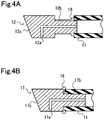
- Figs. 4A and 4B are schematic partial cross-sectional views showing the steps for attaching a standard terminal metal member 17 to the body 11.
- Figs. 5A to 5F are schematic views showing specific shapes of the band-shaped groove portions 12d formed on the insertion portion 12b.
- the body 11 is molded by a known molding method using a heat resistant rubber composition material, and the terminal metal member 12 and the terminal plug 13 are attached to the both ends of the body 11 as the sealing members, respectively.
- the terminal metal member 12 and the terminal plug 13 are attached to the both ends of the body 11 as the sealing members, respectively.
- a known heat resistant adhesive 18 for use as a heat resistant rubber composition material is applied to the insertion portion 12b of the terminal metal member 12 and the insertion portion 13a of the terminal plug 13 (not shown)
- the insertion portion 12b and the insertion portion 13a are inserted into the end portions of the body 11, respectively.
- the size of the transverse cross-section of the insertion portion 12b is set substantially equal to the size of the hollow space of the transverse cross-section of the body 11, to improve air tightness in the interior of the bladder 10A.
- the size of the transverse cross-section of the insertion portion 12b is smaller than the size of the hollow space of the transverse cross-section of the body 11, there is a clearance between the outer peripheral surface of the insertion portion 12b and the inner surface of the body 11, in a state where the terminal metal member 12 is inserted into and fastened to the body 11.
- This clearance is effective as the space for retaining the adhesive 18.
- the body 11 is inflated by pressurization of the interior of the body 11. If the clearance is too great, the interior of the body 11 cannot be maintained in an air-tight condition, although it depends on the degree of the adhesive state formed by the adhesive 18.
- the size of the transverse cross-section of the insertion portion 12b is preferably substantially equal to the size of the hollow space of the transverse cross-section of the body 11.
- the standard terminal member 17 is attached to the body 11 as shown in Fig. 4A and 4B .
- Fig. 4A when the entire outer peripheral surface of an insertion portion 17b of the terminal metal member 17 is applied with the adhesive 18 and the insertion portion 17b is inserted into the hollow space of the body 11, a most part of the adhesive 18 is scraped by the opening edge of the end portion of the body 11, and the scraped adhesive 18 gathers in a space between the opening of the end portion of the body 11 and a stepped portion formed between a head portion 17c and the insertion portion 17b in the terminal metal member 17 as shown in Fig. 4B .
- the plurality of (e.g., three) band-shaped groove portions 12d are provided on the outer peripheral surface of the insertion portion 12b to extend in the direction perpendicular to the longitudinal direction.
- a most part of the adhesive 18 is removed from the outer peripheral surface of the insertion portion 17b, when the insertion portion 17b is inserted into the hollow space of the body 11.
- the adhesive 18 is filled in the band-shaped groove portions 12d and is left between the insertion portion 12b and the body 11.
- the band-shaped groove portions 12d are provided on the outer peripheral surface of the insertion portion 12b to extend in the direction perpendicular to the longitudinal direction. Because of this, the adhesive 18 left between the insertion portion 12b and the body 11 is retained like an annular seal material between the outer peripheral surface of the insertion portion 12b and the inner surface of the body 11 and form a plurality of (e.g., three) adhesive layers 14. By curing the adhesive 18, the insertion portion 12b and the body 11 can be sufficiently adhesively attached together by the plurality of adhesive layers 14, and can be joined together in a sealed state. This makes it possible to provide a more firmly adhesive state (secured state) between the terminal metal member 12 and the body 11 and improve air tightness in the interior of the body 11.
- a more firmly adhesive state secured state
- the size of the transverse cross-section of the insertion portion 12b may be set substantially equal to the size of the transverse cross-section of the hollow space of the body 11. In accordance with this configuration, it is possible to prevent formation of a wasteful clearance between the outer peripheral surface of the insertion portion 12b and the inner surface of the body 11. However, in the case of the standard terminal metal member 17, the adhesive 18 cannot be retained between the insertion portion 12b and the body 11, if the size of the transverse cross-section of the insertion portion 12b is set substantially equal to the size of the transverse cross-section of the hollow space of the body 11.
- the body 11 can be kept in an air-tight condition, and the adhesive 18 can be retained appropriately.
- the adhesive 18 can be retained appropriately.
- the outer peripheral surface of the insertion portion 12b is flat, it is difficult to retain the adhesive 18 stably.
- the plurality of adhesive layers 14 can be formed by forming the plurality of band-shaped groove portions 12d on the outer peripheral surface of the insertion portion 12b, it is possible to adhesively attach the terminal metal member 12 to the body 11 more surely.
- band-shaped groove portions 12d are not particularly limited.
- band-shaped groove portions 12d-1 may have a band shape in which they are wound around the outer peripheral surface of the insertion portion 12b to extend along a direction (lateral direction) perpendicular to the longitudinal direction, but need not extend along the direction perpendicular to the longitudinal direction.
- a configuration in which band-shaped groove portions 12d-2 are inclined with respect to the lateral direction may be used.
- the band-shaped groove portions 12d not only serve as a space in which the adhesive 18 is filled (adhesive retaining function), but also serves to retain the filled adhesive 18 around the insertion portion 12b in an annular shape, like a seal material (have a sealing function).
- the band-shaped groove portions 12d may have any shape so long as they can implement such functions.
- band-shaped groove portions 12d-3 having a corrugated shape may be used.
- the band-shaped groove portion 12d-1 having a greater width and a band-shaped groove portion 12d-4 having a smaller width may coexist.
- a band-shaped groove portion 12d-5 may be added to connect three band-shaped groove portions 12d-1 in the longitudinal direction.
- standard band-shaped portions 12d-1 may be formed at a tip end side and a base end side of the insertion portion 12b, and a broken-line-shaped recess 12d-6 divided in a broken line shape may be formed between them.
- an area of the adhesive layers 14 can be advantageously increased.
- the band-shaped groove portion 12d-1 and the broken-line-shaped recess 12d-6 as shown in Fig. 5F , the band-shaped groove portions 12d-1 at the tip end side and at the base end side of the insertion portion 12b provide the sealing function, and the broken-line-shaped recess 12d-6 between them can form the adhesive layer 14 in the intermediate portion of the insertion portion 12b. This can reduce the amount of the adhesive 18.
- the dimension of the band-shaped groove portion 12d is not particularly limited.
- the width and depth of the band-shaped groove portion 12d may be suitably set based on the specific dimension of the insertion portion 12b and the specific dimension of the body 11, provided that the adhesive retaining function and the sealing function can be implemented.
- the width of the band-shaped groove portion 12d may be within a range of 2 ⁇ 5mm and the depth of the band-shaped groove portion 12d may be within a range of 1 ⁇ 3mm, if the length of the insertion portion 12b is 50mm.
- the number of the band-shaped groove portions 12d formed on the insertion portion 12b is not particularly limited. To implement the adhesive retaining function and the sealing function, at least one band-shaped groove portion 12d may be formed. To ensure a stably adhesive state over the entire outer peripheral surface of the insertion portion 12b, the band-shaped groove portions 12d are preferably formed at three locations which are the tip end side of the insertion portion 12b, the base end side of the head portion 12c, and a portion between them. That is, the band-shaped groove portions 12d are preferably formed at three locations.
- the band-shaped groove portions 12d may be formed at two locations which are the tip end side and the base end side, or at two or more locations between the tip end side and the base end side, in view of conditions such as the length of the insertion portion 12b, or a contact surface area of the band-shaped groove portion 12d with the inner surface of the body 11.
- the bladder 10A of the present embodiment is suitably used as a jig of a hat stringer included in a stiffener of a frame member, to manufacture various kinds of composite material structures using stiffened panels. This will be described with reference to Figs. 6A and 6B , Figs. 7A and 7B , and Figs. 8A and 8B .
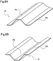
- Figs. 6A and 6B are partial perspective views showing an exemplary configuration of the hat stringer.
- Figs. 7A and 7B are schematic cross-sectional views showing a positional relationship among the bladder 10A, the prepreg, and a mandrel, in the step of curing the prepreg in the autoclave.
- Figs. 8A and 8B are schematic cross-sectional views showing a state where the bladder 10A is drawn out after the prepreg is cured.
- the hat stringer 20 has a rod shape or an elongated-plate shape extending in a particular direction.
- the hat stringer 20 includes a pair of flat band-shaped portions 20a which extend in parallel with each other in its lengthwise direction and a channel portion 20b which is located between the band-shaped portions 20a and is recessed from the surface of the flat portion.
- the upper surface of the channel portion 20b whose opening is directed downward as shown in Fig. 6A is referred to as an inner surface, while the upper surface of the channel portion 20b whose opening is directed upward is referred to as an outer surface.
- the bladder 10A is inserted into the channel portion 20b and used.
- the hat stringer 20 is assembled into a predetermined frame shape conforming to a shape of the structure (structural component). At this time, since the hat stringer 20 is assembled such that its outer surface is located at an outer side, the bladder 10A is inserted into the channel portion 20b. In this state, the prepreg 30 is bonded and attached to the outer surfaces of the band-shaped portions 20a of the hat stringer 20 and to the outer surface of the exposed wall portion 11b of the bladder 10A.
- a method of attaching the prepreg 30 to the outer surfaces is not particularly limited.
- the structure is a body of aircraft, its frame structure is assembled in a cylindrical shape.
- the prepreg 30 may be bonded and stacked while rotating the cylindrical frame structure.
- more layers are stacked together to increase the thickness of the skin in a portion which is required to have enhanced stiffness and strength.
- the skin is entirely thinned to achieve lightweight, while the skin is required to be thickened to enhance strength in a portion in the vicinity of a window, a door, or the like. Therefore, before curing, the thickness of the prepreg 30 is not constant.
- the mandrel 42 which is the jig for maintaining the cylindrical shape is attached to the interior of the cylindrical structure.
- the entire structure is covered with a bagging film 43 and is introduced into the autoclave. Inside the autoclave, this structure is heated under a predetermined temperature and pressurized under a predetermined pressure.
- a high-temperature and high-pressure atmosphere inside the autoclave is transmitted to the entire prepreg 30 via the bagging film 43, and to the interior of the bladder 10A through the pressurization hole 12a of the terminal metal member 12 of the bladder 10A (arrow HO in Fig. 7A ), so that the bladder 10A is inflated.
- the high-temperature and high-pressure atmosphere inside the autoclave is applied to the entire prepreg 30 (arrow H1 in Fig. 7A ).
- the plurality of (three in Fig. 7A ) adhesive layers 14 are formed between the outer peripheral surface of the insertion portion 12b and the inner surface of the body 11.
- the adhesive layers 14 are retained by the band-shaped groove portions 12d formed on the outer peripheral surface of the insertion portion 12b.
- a plurality of annular seal meterials formed by the adhesive layers 18 are provided on the outer peripheral surface of the insertion portion 12b. Because of this, the high-temperature and high-pressure atmosphere inside the bladder 10A does not leak through a clearance between the insertion portion 12b and the body 11, which enables the bladder 10A to be inflated sufficiently.
- the bladder 10A Since the bladder 10A is inflated, a state where the band-shaped portions 20a of the hat stringer 20 (not shown in Fig. 7A ) are pressed against the prepreg 30 by a strong external force is maintained, and curing of the prepreg 30 progresses. After the curing of the prepreg 30 is complete, a stiffened panel structure is attained, in which the frame constituted by the hat stringer 20 and the skin formed by curing the prepreg 30 are firmly adhesively attached to each other and integrated with each other.
- the bladder 10A is drawn out of the region between the cured skin 31 and the hat stringer 20.
- the bladder 10A is provided with the plurality of adhesive layers 14 between the outer peripheral surface of the insertion portion 12b of the terminal metal member 12 and the inner surface of the body 11, as surrounded by the dotted line in Fig. 8A . Since the adhesive layers 14 are formed at three locations which are the tip end side of the insertion portion 12b, the base end side of insertion portion 12b, and the portion between the tip end side and the base end side, the entire insertion portion 12b can be adhesively attached to the body 11.
- the skin 31 does not have a constant thickness, but has unevenness on its inner surface as indicated by a region D surrounded by the dotted line in Fig. 8A .
- the bladder 10A is inserted in between the hat stringer 20 and the skin 31 such that the upper portion of the bladder 10A is curved along the unevenness (region D).
- an external for pulling out the bladder 10A is applied to the head portion 12c of the terminal metal member 12, as indicated by an arrow P in Fig. 8A .
- the plurality of adhesive layers 14 surrounded by the dotted line in Fig. 8A allow the insertion portion 12b and the body 11 to be adhesively attached together stably. Therefore, even when the upper portion of the bladder 10A is curved along the unevenness of the inner surface of the skin 31, the bladder 10A can be drawn out by dragging the head portion 12c of the terminal metal member 12 to outside.
- the mandrel 42 is attached to the interior of the structure, and the entire structure is covered with the bagging film 43 and is introduced into the autoclave.
- the high-temperature and high-pressure atmosphere in the interior of the autoclave is applied to the entire prepreg 30 via the bagging film 43, and is transmitted to the interior of the bladder 10B through the pressurization hole 17a of the terminal metal member 17 of the bladder 10B (arrow HO in Fig. 7B ).
- the high-temperature and high-pressure atmosphere to be applied to the interior of the body 11 leaks from that portion where the body 11 is separated from the insertion portion 17b (arrow H2 in Fig. 7B ).
- the bladder 10B cannot be inflated sufficiently as described above, curing of the prepreg 30 might progress in a state where the band-shaped portions 20a of the hat stringer 20 which are not shown in Fig. 7B are not pressed against the prepreg 30 with a strong external force, and it becomes impossible to manufacture a structure having a proper shape. Therefore, if the adhesive state between the body 11 and the insertion portion 17b in the bladder 10B is insufficient, the bladder 10B cannot be used to manufacture a structure in a next occasion.
- the bladder 10A of the present invention is provided with the band-shaped groove portions 12d on the outer peripheral surface of the insertion portion 12b of the terminal metal member 12, the adhesive state between the terminal metal member 12 and the body 11 can be improved. Because of this, the bladder 10A is drawn out of the region between the cured skin 31 and the hat stringer 20 without lessening the adhesive state between the terminal metal member 12 and the body 11. As a result, the life of the bladder 10A can be extended.
- the adhesive layers 14 retained by the band-shaped groove portions 12d serve as the seal material on the outer peripheral surface of the insertion portion 12b, the air tightness in the interior of the body 11 can be improved more effectively, and the inflated state of the bladder 10A can be maintained stably.
- the present invention is suitably used in a field of manufacturing of composite material structures, in particular, in a field of manufacturing of a stiffened panel structure including a hat stringer.
Landscapes
- Engineering & Computer Science (AREA)
- Mechanical Engineering (AREA)
- Chemical & Material Sciences (AREA)
- Composite Materials (AREA)
- Architecture (AREA)
- Civil Engineering (AREA)
- Structural Engineering (AREA)
- Moulding By Coating Moulds (AREA)
Claims (3)
- Gabarit entrant dans la fabrication d'une structure en matériau composite, le gabarit étant introduit dans une partie de canal (20b) d'une lisse à profil oméga et utilisé lorsque la structure en matériau composite est fabriquée par fixation d'un préimprégné (30) sur une structure de support comportant la lisse à profil oméga (20) en tant qu'élément de support, la partie de canal s'étendant dans le sens longitudinal de la lisse à profil oméga, le gabarit comprenant :un corps (11) de forme tubulaire et composé d'un matériau élastique, etun élément métallique terminal (12) rattaché à une partie terminale du corps et présentant un trou de mise sous pression (12a) permettant de mettre sous pression l'intérieur du corps ;ledit élément métallique terminal présentant une partie une partie d'introduction (12b) introduite dans un espace creux du corps, etladite partie d'introduction ayant une forme de colonne dont la section transversale correspond à la forme d'un contour de l'espace creux du corps ;caractérisé en ce quele corps (11) a une section transversale de forme trapézoïdale, c'est-à-dire une section perpendiculaire au sens longitudinal du corps,la partie d'introduction (12b) est dotée, sur une surface périphérique extérieure, d'une partie à rainure en forme de ruban (12d) s'enroulant autour de la surface périphérique extérieure, etla partie d'introduction est introduite dans l'espace creux du corps lorsqu'un adhésif (18) est apporté dans la partie à rainure en forme de ruban.
- Gabarit entrant dans la fabrication d'une structure en matériau composite selon la revendication 1, dans lequel la partie à rainure en forme de ruban (12d) comporte une pluralité de parties à rainure en forme de ruban prévues sur la partie d'introduction.
- Gabarit entrant dans la fabrication d'une structure en matériau composite selon la revendication 1 ou 2, dans lequel le matériau élastique est un matériau à base de caoutchouc résistant à chaleur.
Applications Claiming Priority (2)
| Application Number | Priority Date | Filing Date | Title |
|---|---|---|---|
| JP2009255520A JP5416554B2 (ja) | 2009-11-06 | 2009-11-06 | 複合材料構造物製造用治具 |
| PCT/JP2010/006439 WO2011055524A1 (fr) | 2009-11-06 | 2010-11-01 | Gabarit pour la fabrication d'une structure en matériau composite |
Publications (3)
| Publication Number | Publication Date |
|---|---|
| EP2497623A1 EP2497623A1 (fr) | 2012-09-12 |
| EP2497623A4 EP2497623A4 (fr) | 2017-11-29 |
| EP2497623B1 true EP2497623B1 (fr) | 2020-12-30 |
Family
ID=43969767
Family Applications (1)
| Application Number | Title | Priority Date | Filing Date |
|---|---|---|---|
| EP10828085.0A Active EP2497623B1 (fr) | 2009-11-06 | 2010-11-01 | Gabarit pour la fabrication d'une structure en matériau composite |
Country Status (4)
| Country | Link |
|---|---|
| US (1) | US8602401B2 (fr) |
| EP (1) | EP2497623B1 (fr) |
| JP (1) | JP5416554B2 (fr) |
| WO (1) | WO2011055524A1 (fr) |
Families Citing this family (19)
| Publication number | Priority date | Publication date | Assignee | Title |
|---|---|---|---|---|
| DE102010024120B4 (de) * | 2010-06-17 | 2014-10-23 | Premium Aerotec Gmbh | Stützprofil |
| US8684343B2 (en) * | 2012-01-06 | 2014-04-01 | Rubbercraft Corporation Of California Ltd | Composite fabrication vent assembly and method |
| US9352514B2 (en) * | 2013-06-19 | 2016-05-31 | The Boeing Company | Fuselage mandrel insert and method |
| JP6184808B2 (ja) | 2013-09-05 | 2017-08-23 | 三菱重工業株式会社 | 中子型および中空構造体の製造方法 |
| US9623641B1 (en) * | 2013-09-24 | 2017-04-18 | The Boeing Company | Method and apparatus for reinforcing a bladder |
| US9914244B2 (en) * | 2014-08-04 | 2018-03-13 | The Boeing Company | Bladder system for curing composite parts |
| DE102014215965A1 (de) * | 2014-08-12 | 2016-02-18 | Bayerische Motoren Werke Aktiengesellschaft | Verfahren zur Herstellung eines faserverstärkten Kunststoffbauteils |
| US9862122B2 (en) | 2014-08-14 | 2018-01-09 | The Boeing Company | Reinforced bladder |
| US10086534B2 (en) * | 2014-10-17 | 2018-10-02 | The Boeing Company | Multifunctional mandrel end cap and method |
| US10507601B2 (en) | 2016-05-17 | 2019-12-17 | Rubbercraft Corporation Of California, Ltd. | Tri-layer bladder and related systems and methods for fabricating composite structures |
| CN109562578B (zh) * | 2016-09-29 | 2020-12-08 | 株式会社斯巴鲁 | 复合材料结构体和复合材料结构体的制造方法 |
| US20180194071A1 (en) * | 2017-01-06 | 2018-07-12 | Applied Composite Technology Aerospace, Inc. | Variable Volume Support Member for Cure of Composite Structure |
| ES2954328T3 (es) | 2017-07-25 | 2023-11-21 | Subaru Corp | Plantilla de moldeo de materiales compuestos y método de moldeo de materiales compuestos |
| JP6971690B2 (ja) * | 2017-08-03 | 2021-11-24 | 三菱重工業株式会社 | 可撓性マンドレル、複合材部品の製造方法 |
| AU2018345731B2 (en) | 2017-10-03 | 2023-11-09 | Rubbercraft Corporation Of California, Ltd. | Fluoroelastomer covered elastomeric for composite manufacturing |
| JP6715226B2 (ja) | 2017-10-25 | 2020-07-01 | 株式会社Subaru | 複合材成形治具及び複合材成形方法 |
| JP7116805B2 (ja) * | 2019-01-17 | 2022-08-10 | 川崎重工業株式会社 | 複合材料構造物製造用治具およびその製造方法、並びに複合材料構造物の製造方法 |
| DE102019005910A1 (de) * | 2019-08-22 | 2021-02-25 | Siempelkamp Maschinen- Und Anlagenbau Gmbh | Verfahren und Vorrichtung zum Erzeugen eines Bauelements |
| US12070915B2 (en) * | 2021-01-04 | 2024-08-27 | The Boeing Company | Autoclave system, bladder assembly, and associated method for forming a part |
Family Cites Families (16)
| Publication number | Priority date | Publication date | Assignee | Title |
|---|---|---|---|---|
| US2139745A (en) * | 1937-04-07 | 1938-12-13 | Howard W Goodall | Hose coupling |
| CH459549A (de) * | 1966-07-15 | 1968-07-15 | Ciba Geigy | Verfahren zur Herstellung fasergewickelter Kunststoff-Rohrbögen |
| US4632328A (en) | 1985-07-25 | 1986-12-30 | The B. F. Goodrich Company | Inflatable mandrel and method therefor |
| JP2935722B2 (ja) * | 1990-02-28 | 1999-08-16 | 富士重工業株式会社 | 航空機の胴体構造およびその成形方法 |
| US5223067A (en) | 1990-02-28 | 1993-06-29 | Fuji Jukogyo Kabushiki Kaisha | Method of fabricating aircraft fuselage structure |
| JPH05116162A (ja) * | 1991-04-30 | 1993-05-14 | Mitsubishi Heavy Ind Ltd | 複合材成形用治具 |
| US6143236A (en) * | 1994-02-09 | 2000-11-07 | Radius Engineering, Inc. | Method for manufacturing composite shafts with injection molded, rigidized bladder with varying wall thickness |
| JPH08770A (ja) | 1994-06-17 | 1996-01-09 | Yonetsukusu Kk | ラケットの成形方法 |
| US5939007A (en) | 1994-08-31 | 1999-08-17 | Sikorsky Aircraft Corporation | Method for manufacture of a fiber reinforced composite spar for rotary wing aircraft |
| JPH08281833A (ja) * | 1995-04-17 | 1996-10-29 | Nippon Oil Co Ltd | 繊維強化複合材料ロール |
| DE19932956B4 (de) * | 1998-07-15 | 2009-04-09 | Toyoda Gosei Co., Ltd. | Schlauchverbindung |
| JP3938762B2 (ja) * | 2003-05-30 | 2007-06-27 | 川崎重工業株式会社 | 板状構造体、補強材及び板状構造体の製造方法 |
| JP4928115B2 (ja) * | 2005-11-08 | 2012-05-09 | 富士重工業株式会社 | 成形方法及び成形治具 |
| FR2898539B1 (fr) * | 2006-03-20 | 2008-05-23 | Eads Ccr Groupement D Interet | Procede de realisation de panneaux raidis en materiau composite et panneaux ainsi realises |
| DE102006035619B3 (de) * | 2006-07-31 | 2007-11-29 | Airbus Deutschland Gmbh | Anschlussvorrichtung für einen Formkern zur Herstellung eines Faserverbundbauteils, insbesondere für die Luft- und Raumfahrt |
| JP2009178988A (ja) * | 2008-01-31 | 2009-08-13 | Kurashiki Kako Co Ltd | 成形用中空部材 |
-
2009
- 2009-11-06 JP JP2009255520A patent/JP5416554B2/ja active Active
-
2010
- 2010-11-01 WO PCT/JP2010/006439 patent/WO2011055524A1/fr not_active Ceased
- 2010-11-01 US US13/505,366 patent/US8602401B2/en active Active
- 2010-11-01 EP EP10828085.0A patent/EP2497623B1/fr active Active
Also Published As
| Publication number | Publication date |
|---|---|
| WO2011055524A1 (fr) | 2011-05-12 |
| US20120235336A1 (en) | 2012-09-20 |
| US8602401B2 (en) | 2013-12-10 |
| JP5416554B2 (ja) | 2014-02-12 |
| EP2497623A1 (fr) | 2012-09-12 |
| JP2011098527A (ja) | 2011-05-19 |
| EP2497623A4 (fr) | 2017-11-29 |
Similar Documents
| Publication | Publication Date | Title |
|---|---|---|
| EP2497623B1 (fr) | Gabarit pour la fabrication d'une structure en matériau composite | |
| US7897004B2 (en) | Method for fabricating stringers | |
| KR101882535B1 (ko) | 강성/가단성 smp 장치를 사용하여 복합물 부재를 함께-본딩 또는 함께-경화하기 위한 방법 및 시스템 | |
| EP3549751B1 (fr) | Procédé de production d'une structure en matériau composite | |
| US9278748B2 (en) | Processes to fabricate composite tubular-reinforced panels integrating skin and stringers and the panels thereby fabricated | |
| CN103180123B (zh) | 用于借助形状记忆聚合物设备来形成一体式复合部件的方法和系统 | |
| KR20090047445A (ko) | 항공기용 개선 복합재 수지 윈도 프레임 | |
| EP2949458B1 (fr) | Procédé de fabrication de panneaux de fibres de carbone renforcés par des longerons oméga | |
| US9724848B2 (en) | Collapsible, coiled mandrel | |
| US20090294040A1 (en) | Process and jig for manufacturing composite material structures | |
| US9120553B2 (en) | Process and a hollow body for producing a component having at least one hollow profile | |
| KR20090128421A (ko) | 복합 소재로부터 부품, 특히 항공기 동체 부분의 제조 방법 및 장치 | |
| JP3938762B2 (ja) | 板状構造体、補強材及び板状構造体の製造方法 | |
| CN109789650A (zh) | 用复合修复帽修复复合桁条的方法 | |
| CN111791517B (zh) | 中空囊状件修复方法 | |
| WO2022099707A1 (fr) | Moule à noyau destiné à la production d'un élément de renforcement en forme de chapeau | |
| CN114506095A (zh) | 一种用于制作帽型增强构件的芯模 | |
| JP7116805B2 (ja) | 複合材料構造物製造用治具およびその製造方法、並びに複合材料構造物の製造方法 | |
| US20130037215A1 (en) | Device for the master moulding technique production of an integral structural component made of a fibre composite material reinforced by stringers for an aircraft | |
| CN120840119A (zh) | 适于制造帽型长桁加筋壁板构件的气囊组件及模具组件 |
Legal Events
| Date | Code | Title | Description |
|---|---|---|---|
| PUAI | Public reference made under article 153(3) epc to a published international application that has entered the european phase |
Free format text: ORIGINAL CODE: 0009012 |
|
| 17P | Request for examination filed |
Effective date: 20120430 |
|
| AK | Designated contracting states |
Kind code of ref document: A1 Designated state(s): AL AT BE BG CH CY CZ DE DK EE ES FI FR GB GR HR HU IE IS IT LI LT LU LV MC MK MT NL NO PL PT RO RS SE SI SK SM TR |
|
| DAX | Request for extension of the european patent (deleted) | ||
| RA4 | Supplementary search report drawn up and despatched (corrected) |
Effective date: 20171030 |
|
| RIC1 | Information provided on ipc code assigned before grant |
Ipc: B29C 43/12 20060101ALI20171024BHEP Ipc: B29L 31/30 20060101ALI20171024BHEP Ipc: B64C 1/06 20060101ALI20171024BHEP Ipc: B29C 43/44 20060101ALI20171024BHEP Ipc: B29C 70/06 20060101AFI20171024BHEP |
|
| GRAP | Despatch of communication of intention to grant a patent |
Free format text: ORIGINAL CODE: EPIDOSNIGR1 |
|
| STAA | Information on the status of an ep patent application or granted ep patent |
Free format text: STATUS: GRANT OF PATENT IS INTENDED |
|
| INTG | Intention to grant announced |
Effective date: 20200730 |
|
| GRAS | Grant fee paid |
Free format text: ORIGINAL CODE: EPIDOSNIGR3 |
|
| RIN1 | Information on inventor provided before grant (corrected) |
Inventor name: TAKAHASHI, TOMOYA Inventor name: SANA, TOSHIKAZU Inventor name: HANAFUSA, YASUO |
|
| GRAA | (expected) grant |
Free format text: ORIGINAL CODE: 0009210 |
|
| STAA | Information on the status of an ep patent application or granted ep patent |
Free format text: STATUS: THE PATENT HAS BEEN GRANTED |
|
| AK | Designated contracting states |
Kind code of ref document: B1 Designated state(s): AL AT BE BG CH CY CZ DE DK EE ES FI FR GB GR HR HU IE IS IT LI LT LU LV MC MK MT NL NO PL PT RO RS SE SI SK SM TR |
|
| REG | Reference to a national code |
Ref country code: GB Ref legal event code: FG4D |
|
| REG | Reference to a national code |
Ref country code: DE Ref legal event code: R096 Ref document number: 602010066262 Country of ref document: DE |
|
| REG | Reference to a national code |
Ref country code: AT Ref legal event code: REF Ref document number: 1349503 Country of ref document: AT Kind code of ref document: T Effective date: 20210115 |
|
| REG | Reference to a national code |
Ref country code: IE Ref legal event code: FG4D |
|
| PG25 | Lapsed in a contracting state [announced via postgrant information from national office to epo] |
Ref country code: FI Free format text: LAPSE BECAUSE OF FAILURE TO SUBMIT A TRANSLATION OF THE DESCRIPTION OR TO PAY THE FEE WITHIN THE PRESCRIBED TIME-LIMIT Effective date: 20201230 Ref country code: RS Free format text: LAPSE BECAUSE OF FAILURE TO SUBMIT A TRANSLATION OF THE DESCRIPTION OR TO PAY THE FEE WITHIN THE PRESCRIBED TIME-LIMIT Effective date: 20201230 Ref country code: NO Free format text: LAPSE BECAUSE OF FAILURE TO SUBMIT A TRANSLATION OF THE DESCRIPTION OR TO PAY THE FEE WITHIN THE PRESCRIBED TIME-LIMIT Effective date: 20210330 Ref country code: GR Free format text: LAPSE BECAUSE OF FAILURE TO SUBMIT A TRANSLATION OF THE DESCRIPTION OR TO PAY THE FEE WITHIN THE PRESCRIBED TIME-LIMIT Effective date: 20210331 |
|
| REG | Reference to a national code |
Ref country code: AT Ref legal event code: MK05 Ref document number: 1349503 Country of ref document: AT Kind code of ref document: T Effective date: 20201230 |
|
| PG25 | Lapsed in a contracting state [announced via postgrant information from national office to epo] |
Ref country code: SE Free format text: LAPSE BECAUSE OF FAILURE TO SUBMIT A TRANSLATION OF THE DESCRIPTION OR TO PAY THE FEE WITHIN THE PRESCRIBED TIME-LIMIT Effective date: 20201230 Ref country code: LV Free format text: LAPSE BECAUSE OF FAILURE TO SUBMIT A TRANSLATION OF THE DESCRIPTION OR TO PAY THE FEE WITHIN THE PRESCRIBED TIME-LIMIT Effective date: 20201230 Ref country code: BG Free format text: LAPSE BECAUSE OF FAILURE TO SUBMIT A TRANSLATION OF THE DESCRIPTION OR TO PAY THE FEE WITHIN THE PRESCRIBED TIME-LIMIT Effective date: 20210330 |
|
| REG | Reference to a national code |
Ref country code: NL Ref legal event code: MP Effective date: 20201230 |
|
| PG25 | Lapsed in a contracting state [announced via postgrant information from national office to epo] |
Ref country code: HR Free format text: LAPSE BECAUSE OF FAILURE TO SUBMIT A TRANSLATION OF THE DESCRIPTION OR TO PAY THE FEE WITHIN THE PRESCRIBED TIME-LIMIT Effective date: 20201230 |
|
| REG | Reference to a national code |
Ref country code: LT Ref legal event code: MG9D |
|
| PG25 | Lapsed in a contracting state [announced via postgrant information from national office to epo] |
Ref country code: SK Free format text: LAPSE BECAUSE OF FAILURE TO SUBMIT A TRANSLATION OF THE DESCRIPTION OR TO PAY THE FEE WITHIN THE PRESCRIBED TIME-LIMIT Effective date: 20201230 Ref country code: PT Free format text: LAPSE BECAUSE OF FAILURE TO SUBMIT A TRANSLATION OF THE DESCRIPTION OR TO PAY THE FEE WITHIN THE PRESCRIBED TIME-LIMIT Effective date: 20210430 Ref country code: RO Free format text: LAPSE BECAUSE OF FAILURE TO SUBMIT A TRANSLATION OF THE DESCRIPTION OR TO PAY THE FEE WITHIN THE PRESCRIBED TIME-LIMIT Effective date: 20201230 Ref country code: CZ Free format text: LAPSE BECAUSE OF FAILURE TO SUBMIT A TRANSLATION OF THE DESCRIPTION OR TO PAY THE FEE WITHIN THE PRESCRIBED TIME-LIMIT Effective date: 20201230 Ref country code: EE Free format text: LAPSE BECAUSE OF FAILURE TO SUBMIT A TRANSLATION OF THE DESCRIPTION OR TO PAY THE FEE WITHIN THE PRESCRIBED TIME-LIMIT Effective date: 20201230 Ref country code: NL Free format text: LAPSE BECAUSE OF FAILURE TO SUBMIT A TRANSLATION OF THE DESCRIPTION OR TO PAY THE FEE WITHIN THE PRESCRIBED TIME-LIMIT Effective date: 20201230 Ref country code: LT Free format text: LAPSE BECAUSE OF FAILURE TO SUBMIT A TRANSLATION OF THE DESCRIPTION OR TO PAY THE FEE WITHIN THE PRESCRIBED TIME-LIMIT Effective date: 20201230 |
|
| PG25 | Lapsed in a contracting state [announced via postgrant information from national office to epo] |
Ref country code: PL Free format text: LAPSE BECAUSE OF FAILURE TO SUBMIT A TRANSLATION OF THE DESCRIPTION OR TO PAY THE FEE WITHIN THE PRESCRIBED TIME-LIMIT Effective date: 20201230 Ref country code: AT Free format text: LAPSE BECAUSE OF FAILURE TO SUBMIT A TRANSLATION OF THE DESCRIPTION OR TO PAY THE FEE WITHIN THE PRESCRIBED TIME-LIMIT Effective date: 20201230 |
|
| PG25 | Lapsed in a contracting state [announced via postgrant information from national office to epo] |
Ref country code: IS Free format text: LAPSE BECAUSE OF FAILURE TO SUBMIT A TRANSLATION OF THE DESCRIPTION OR TO PAY THE FEE WITHIN THE PRESCRIBED TIME-LIMIT Effective date: 20210430 |
|
| REG | Reference to a national code |
Ref country code: DE Ref legal event code: R097 Ref document number: 602010066262 Country of ref document: DE |
|
| PG25 | Lapsed in a contracting state [announced via postgrant information from national office to epo] |
Ref country code: AL Free format text: LAPSE BECAUSE OF FAILURE TO SUBMIT A TRANSLATION OF THE DESCRIPTION OR TO PAY THE FEE WITHIN THE PRESCRIBED TIME-LIMIT Effective date: 20201230 |
|
| PLBE | No opposition filed within time limit |
Free format text: ORIGINAL CODE: 0009261 |
|
| STAA | Information on the status of an ep patent application or granted ep patent |
Free format text: STATUS: NO OPPOSITION FILED WITHIN TIME LIMIT |
|
| PG25 | Lapsed in a contracting state [announced via postgrant information from national office to epo] |
Ref country code: DK Free format text: LAPSE BECAUSE OF FAILURE TO SUBMIT A TRANSLATION OF THE DESCRIPTION OR TO PAY THE FEE WITHIN THE PRESCRIBED TIME-LIMIT Effective date: 20201230 Ref country code: ES Free format text: LAPSE BECAUSE OF FAILURE TO SUBMIT A TRANSLATION OF THE DESCRIPTION OR TO PAY THE FEE WITHIN THE PRESCRIBED TIME-LIMIT Effective date: 20201230 |
|
| 26N | No opposition filed |
Effective date: 20211001 |
|
| PG25 | Lapsed in a contracting state [announced via postgrant information from national office to epo] |
Ref country code: SI Free format text: LAPSE BECAUSE OF FAILURE TO SUBMIT A TRANSLATION OF THE DESCRIPTION OR TO PAY THE FEE WITHIN THE PRESCRIBED TIME-LIMIT Effective date: 20201230 |
|
| PG25 | Lapsed in a contracting state [announced via postgrant information from national office to epo] |
Ref country code: IS Free format text: LAPSE BECAUSE OF FAILURE TO SUBMIT A TRANSLATION OF THE DESCRIPTION OR TO PAY THE FEE WITHIN THE PRESCRIBED TIME-LIMIT Effective date: 20210430 |
|
| PG25 | Lapsed in a contracting state [announced via postgrant information from national office to epo] |
Ref country code: MC Free format text: LAPSE BECAUSE OF FAILURE TO SUBMIT A TRANSLATION OF THE DESCRIPTION OR TO PAY THE FEE WITHIN THE PRESCRIBED TIME-LIMIT Effective date: 20201230 |
|
| REG | Reference to a national code |
Ref country code: CH Ref legal event code: PL |
|
| GBPC | Gb: european patent ceased through non-payment of renewal fee |
Effective date: 20211101 |
|
| PG25 | Lapsed in a contracting state [announced via postgrant information from national office to epo] |
Ref country code: LU Free format text: LAPSE BECAUSE OF NON-PAYMENT OF DUE FEES Effective date: 20211101 Ref country code: BE Free format text: LAPSE BECAUSE OF NON-PAYMENT OF DUE FEES Effective date: 20211130 |
|
| REG | Reference to a national code |
Ref country code: BE Ref legal event code: MM Effective date: 20211130 |
|
| PG25 | Lapsed in a contracting state [announced via postgrant information from national office to epo] |
Ref country code: IE Free format text: LAPSE BECAUSE OF NON-PAYMENT OF DUE FEES Effective date: 20211101 Ref country code: GB Free format text: LAPSE BECAUSE OF NON-PAYMENT OF DUE FEES Effective date: 20211101 |
|
| PG25 | Lapsed in a contracting state [announced via postgrant information from national office to epo] |
Ref country code: HU Free format text: LAPSE BECAUSE OF FAILURE TO SUBMIT A TRANSLATION OF THE DESCRIPTION OR TO PAY THE FEE WITHIN THE PRESCRIBED TIME-LIMIT; INVALID AB INITIO Effective date: 20101101 Ref country code: CY Free format text: LAPSE BECAUSE OF FAILURE TO SUBMIT A TRANSLATION OF THE DESCRIPTION OR TO PAY THE FEE WITHIN THE PRESCRIBED TIME-LIMIT Effective date: 20201230 |
|
| PG25 | Lapsed in a contracting state [announced via postgrant information from national office to epo] |
Ref country code: SM Free format text: LAPSE BECAUSE OF FAILURE TO SUBMIT A TRANSLATION OF THE DESCRIPTION OR TO PAY THE FEE WITHIN THE PRESCRIBED TIME-LIMIT Effective date: 20201230 Ref country code: LI Free format text: LAPSE BECAUSE OF NON-PAYMENT OF DUE FEES Effective date: 20220630 Ref country code: CH Free format text: LAPSE BECAUSE OF NON-PAYMENT OF DUE FEES Effective date: 20220630 |
|
| PG25 | Lapsed in a contracting state [announced via postgrant information from national office to epo] |
Ref country code: MK Free format text: LAPSE BECAUSE OF FAILURE TO SUBMIT A TRANSLATION OF THE DESCRIPTION OR TO PAY THE FEE WITHIN THE PRESCRIBED TIME-LIMIT Effective date: 20201230 |
|
| PG25 | Lapsed in a contracting state [announced via postgrant information from national office to epo] |
Ref country code: TR Free format text: LAPSE BECAUSE OF FAILURE TO SUBMIT A TRANSLATION OF THE DESCRIPTION OR TO PAY THE FEE WITHIN THE PRESCRIBED TIME-LIMIT Effective date: 20201230 |
|
| PG25 | Lapsed in a contracting state [announced via postgrant information from national office to epo] |
Ref country code: MT Free format text: LAPSE BECAUSE OF FAILURE TO SUBMIT A TRANSLATION OF THE DESCRIPTION OR TO PAY THE FEE WITHIN THE PRESCRIBED TIME-LIMIT Effective date: 20201230 |
|
| PGFP | Annual fee paid to national office [announced via postgrant information from national office to epo] |
Ref country code: FR Payment date: 20250930 Year of fee payment: 16 |
|
| PGFP | Annual fee paid to national office [announced via postgrant information from national office to epo] |
Ref country code: DE Payment date: 20250930 Year of fee payment: 16 |
|
| PGFP | Annual fee paid to national office [announced via postgrant information from national office to epo] |
Ref country code: IT Payment date: 20251022 Year of fee payment: 16 |