EP2497627B1 - Kit de réparation pour crevaison - Google Patents
Kit de réparation pour crevaison Download PDFInfo
- Publication number
- EP2497627B1 EP2497627B1 EP09851076.1A EP09851076A EP2497627B1 EP 2497627 B1 EP2497627 B1 EP 2497627B1 EP 09851076 A EP09851076 A EP 09851076A EP 2497627 B1 EP2497627 B1 EP 2497627B1
- Authority
- EP
- European Patent Office
- Prior art keywords
- compressed air
- bottle
- mounting
- opening portion
- compressor device
- Prior art date
- Legal status (The legal status is an assumption and is not a legal conclusion. Google has not performed a legal analysis and makes no representation as to the accuracy of the status listed.)
- Active
Links
Images





Classifications
-
- B—PERFORMING OPERATIONS; TRANSPORTING
- B60—VEHICLES IN GENERAL
- B60S—SERVICING, CLEANING, REPAIRING, SUPPORTING, LIFTING, OR MANOEUVRING OF VEHICLES, NOT OTHERWISE PROVIDED FOR
- B60S5/00—Servicing, maintaining, repairing, or refitting of vehicles
- B60S5/04—Supplying air for tyre inflation
- B60S5/043—Supplying air for tyre inflation characterised by the inflation control means or the drive of the air pressure system
- B60S5/046—Supplying air for tyre inflation characterised by the inflation control means or the drive of the air pressure system using electrical or electronical means
-
- B—PERFORMING OPERATIONS; TRANSPORTING
- B29—WORKING OF PLASTICS; WORKING OF SUBSTANCES IN A PLASTIC STATE IN GENERAL
- B29C—SHAPING OR JOINING OF PLASTICS; SHAPING OF MATERIAL IN A PLASTIC STATE, NOT OTHERWISE PROVIDED FOR; AFTER-TREATMENT OF THE SHAPED PRODUCTS, e.g. REPAIRING
- B29C73/00—Repairing of articles made from plastics or substances in a plastic state, e.g. of articles shaped or produced by using techniques covered by this subclass or subclass B29D
- B29C73/16—Auto-repairing or self-sealing arrangements or agents
- B29C73/166—Devices or methods for introducing sealing compositions into articles
-
- B—PERFORMING OPERATIONS; TRANSPORTING
- B29—WORKING OF PLASTICS; WORKING OF SUBSTANCES IN A PLASTIC STATE IN GENERAL
- B29L—INDEXING SCHEME ASSOCIATED WITH SUBCLASS B29C, RELATING TO PARTICULAR ARTICLES
- B29L2030/00—Pneumatic or solid tyres or parts thereof
Definitions
- the present invention relates to a puncture repair kit for making an emergency repair to a punctured tire by sequentially injecting a puncture sealant and compressed air into the tire.
- the features of the preamble of the independent claim are known from EP 1 291 158 A1 .
- Related technologies are known from EP 1 605 162 A2 and DE 198 46 451 A1 .
- Patent Document 1 suggests a puncture repair kit for making emergency repairs to a punctured tire by pumping up the tire through sequential injection of a puncture sealant and compressed air into the tire, and then running a vehicle with the ti re in this state, such that the puncture sealant covers the enti re inner cavity surface of the ti re to seal the puncture as an emergency repair.
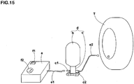
- This kind of a repair kit includes a compressor device a generating compressed air; and a bottle unit d including a bottle container b storing a puncture sealant and a cap c attached upon an opening portion of the bottle container b, as shown in Fig. 15 .
- the cap c is formed with an air intake opening portion c1 for feeding compressed air into the bottle container and a sealant/compressed air retrieval opening portion c2 for sequentially retrieving the puncture sealant and the compressed air from the bottle container b by the feeding of the compressed air.
- the air intake opening porti on c1 is connected to an air supply hose e1 from the compressor device a, and the sealant/compressed air retrieval opening portion c2 is coupled to one end of a feeding hose e2 for connection of an air valve of a tire T.
- the foregoing repair kit requi res the two hoses e1 and e2 which are likely to be laid in an incorrect manner.
- the bottle unit d is less stable and may turn over during operation, so that a required amount of puncture sealant cannot be injected.
- the inventor thus suggests that a compressed air discharge openi ng portion of the compressor devi ce a and the air intake opening portion c1 of the bottle unit d be fitted and connected directly together. Accordingly, the bottle unit d and the compressor device a can be integrated and lowered in position of a gravity center, thereby suppressing turnover of the bottle unit d with increased stability. Besides, this arrangement does not need the hose e1 on the air intake side, thereby eliminating a possibility of incorrect hose laying.
- the bottle unit d and the compressor device a are connected while the two are lifted. Therefore, there is a ri sk that the compressor devi ce a may fall down during operation and a power switch f1 or a pressure gauge f2 provided on the upper surface of the compressor device a is broken. since the compressor device a is formed in as small a size as possible, and is placed on the ground and used in a low position, the power switch f1 and the pressure gauge f2 are to be formed on the upper side of the compressor device a, from the viewpoint of operability.
- the inventor suggests that the power switch f1 and the pressure gauge f2 be attached to depressions on the upper surface of the compressor device a, so that, even if the compressor device a falls down, the power switch f1 and the pressure gauge f2 are protected from breakage due to collision against the ground. In this case, however, when the compressor device a is used in the rain, rainwater piles up in the depressions to cause another problem of occurrence of an electrical failure.
- an object of the present invention is to provide a puncture repair kit that allows direct connection between a bottle unit and a compressor device to suppress turnover of the bottle unit and eliminates one of two hoses to lose a possibility of incorrect hose laying; prevents breakage of a power switch and a pressure gauge at falling of the compressor device; and even if the kit is used in the rain, suppresses a failure resulting from rainwater.
- an invention of claim 1 of the present invention is a puncture repair kit, comprising:
- This allows di rect connecti on of the compressor device and the bottle unit. Accordingly, the two can be integrated and lowered in position of a gravity center, thereby to suppress turndown of the ki t wi th increased stability at installation.
- the present invention does not need a conventional hose on the air intake side, thereby eliminating a possibility of incorrect hose laying.
- the power switch and the pressure gauge are mounted upon the bottom portions of the mounting depressions on the upper surface of the storage case, at a distance of 3 to 15 mm downward from the upper surface. This makes it possible to prevent that, even if the compressor device falls down, the power switch and the pressure gauge collide directly against the ground and are broken.
- drainage channels are formed on the upper surface so as to extend at a downward incline from the mounting depressions toward the outer wall surfaces of the storage case. Therefore, even if the kit is used in the rain, rainwater does not pile up in the mounting depressions, thereby making it possible to prevent occurrence of an electric failure resulting from rainwater.
- a puncture repair kit 1 of this embodiment includes a compressor device 2 and a bottle unit 3, and the bottle unit 3 is formed by a bottle container 4 storing a puncture sealant and a cap 6 mounted upon an opening portion 5 (shown in Fig. 6 ) of the bottle container 4.
- a feeding hose 29 is joined in advance to a sealant/compressed air retrieval opening portion 7 of the bottle unit 3.
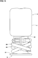
- the feeding hose 29 is wound around the cap 6 and stored in the joined state within a vehicle, as shown in Fig. 14 .
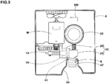
- the compressor device 2 is configured to store in a storage case 9, at least a power switch SW, a compressor main body 13 that is driven by the power switch sw and generates compressed ai r, and a pressure gauge 22 that measures a pressure of the compressed air from the compressor main body 13.
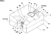
- the storage case 9 is formed in the shape of a rectangular box with a small height, in which a peripheral wall portion has four sides surrounded by side plate portions 14a, and has upper and lower ends closed by an upper plate portion 14U and a lower plate portion 14L.
- the storage case 9 is capable of being disassembled into upper and lower case portions 9u and 9L.
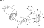
- the compressor main body 13 includes a motor M; a piston 10 coupled to the motor M via a crank mechanism 17; and a cylinder 12 that stores the piston 10 in a reciprocable manner and forms a pump chamber 11 for compressing air between the cylinder 12 and the piston 10.
- the motor M may use any of various commercialized DC motors operating with a 12-v direct current power source in an automobile.
- the motor M is connected to a power cord with a power plug 15 at an end connectable to a cigarette lighter socket in an automobile, via the power switch SW attached to the upper plate portion 14U of the storage case 9.
- the power plug 15 is stored removably in a depression (not shown) of the lower plate portion 14L.
- the piston 10 is formed with an air intake valve 19 using an air intake hole 19A that extends so as to penetrate the piston 10 in a direction of an axial core thereof, and a valve 19B such as an elastic body of rubber, synthetic resin, metal, or the like, for example, to close the air intake hole 19A, with a spring property from the pump chamber side.
- a valve 19B such as an elastic body of rubber, synthetic resin, metal, or the like, for example, to close the air intake hole 19A, with a spring property from the pump chamber side.
- the cyl i nder 12 includes integrally a circular cylinder main body 20 forming the pump chamber 11 and a cylinder subpart 21 at a back end side of the cylinder main body 20 to form a surge tank chamber 21A for reserving compressed air from the pump chamber 11 and reducing pressure pulsation of the piston 10.
- the surge tank chamber 21A communicates with the pump chamber 11 vi a a small hole 20A1 formed on a partition wall 20A closing a back end of the cylinder main body 20.
- a compressed air discharge opening portion 8 for discharging compressed air is formed so as to protrude from a peripheral wall of the cylinder subpart 21.
- a first coupl i ng porti on 24A for mounti ng the pressure gauge 22 and a second coupling portion 24B for mounting a relief valve 23, are provided so as to protrude in different directions from the peripheral wall of the cylinder subpart 21.
- the compressed air discharge opening portion 8 includes a cylindrical portion 25 protruding from the cylinder subpart 21, and the cylindrical portion 25 has a discharge flow path 26 therewithin so as to extend from the surge tank chamber 21A.
- the discharge flow path 26 forms at an opening end side thereof a nozzle receiver 28 connected to the air intake opening portion 27 provided on the bottle unit 3.
- the nozzle receiver 28 has a parallel hole portion 28A with a constant inner diameter, and front and back tapered hol e porti ons 28B and 28c formed i n the shape of a cone tapered toward the cyl i nder subpart 21 on front and back si des of the parallel hole portion 28A.
- the bottle unit 3 is formed by the bottle container 4 storing a puncture sealant and the cap 6 attached upon the opening portion 5 of the bottle container 4, and is directly connected to the compressor device 2, in an inverted state with the cap 6 faced downward.
- the bottle container 4 has the small-diameter cylindrical opening portion 5 protruding from a lower end of the bottle waist portion 30 through which a puncture sealant can be taken in and out.
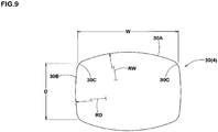
- the bottle waist portion 30 is formed in an approximately rectangular shape in which a horizontal cross section orthogonal to a direction of height is surrounded by a pair of longer side portions 30A and a pair of shorter side portions 30B.
- the longer side portions 30A and the shorter side portions 30B are curved in a convex arc shape toward the outside of the bottle.
- the bottle wai st porti on 30 of the bottle container 4 is preferably formed in an approximately rectangular shape since the compressor device 2 has an approximately rectangular shape.
- the bottle container 4 is placed under a high internal pressure of near 350 kPa, for example.
- the bottle waist portion 30 is circular in cross section, the bottle waist portion 30 expands evenly in a radial direction due to the internal pressure, and therefore the deformation of the bottle waist portion 30 filled with compressed air is less recognized, which provides a user with a smaller feeling of anxiety.
- the bottle waist portion 30 is rectangular in cross section, the bottle waist portion 30 does not expand uniformly but deforms so as to change from a rectangular shape to a circular shape in cross section, due to the internal pressure, and therefore the amount of the deformation may be felt larger than actual. Therefore, the deformation may generate a sense of anxiety about a burst or the like in a user, even though the deformation is within a pressure-resistant range.
- the longer side portions 30A and the shorter side portions 30B are formed in advance in a convex arc shape which is near a shape deformed on expansion. Accordingly, it is possible to make the deformation of the bottle waist portion 30 less recognizable at filling of compressed air, while improving the bottle waist portion 30 in storage property, thereby decreasing the user's anxiety.
- the inventor have conducted experiments and revealed that it is important to reduce the amount of expansion of the bottle waist portion 30 on the longer side to alleviate the user's anxiety, and, for this end, it is preferred to set the length W larger and set the curvature radius RW smaller on the longer side. If the ratio W/D is less than 1.3 or the ratio RW/W exceeds 3.0, the length W becomes relatively small or the curvature radius RW becomes large, which leads to increase in amount of expansion of the bottle waist portion 30 on the longer side. In contrast, if the ratio W/D exceeds 1.7 or the ratio RW/W is less than 0.5, there arises a disadvantage in storage property.
- the ratio RD/D exceeds 20.0, the amount of expansi on of the bottle wai st porti on 30 on the shorter si de increases and the deformation of the bottle waist portion 30 filled with compressed air becomes large, and in contrast, if the ratio RD/D becomes less than 0.5, there arises a disadvantage in storage property.
- each of corners of the bottle waist portion 30 at which the longer side portions 30A and the shorter side portions 30B intersect are preferably formed by an arc 30C with a curvature radius of 15 mm ⁇ 5 mm to lessen stress concentration and enhance pressure-resistant performance.
- the cap 6 has a cap main body 6A including integrally a disc-like bottom plate portion 31 constituting a bottom surface 6S; a bottle mounting portion 32 for mounting the opening portion 5 of the bottle container 4; and a constricted waist portion 33 disposed between the bottom plate portion 31 and the bottle mounting portion 32.
- Protruded from the wai st porti on 33 are the air intake openi ng porti on 27 wi th an intake opening 27a for feeding compressed air from the compressed air discharge opening portion 8 into the bottle container 4 and the sealant/compressed air retrieval opening portion 7 with a retrieval opening 7a for sequentially retrieving the puncture sealant and the compressed air from the bottle container 4 by the feeding of the compressed air.
- an air flow path 35 extendi ng from the intake opening 27a into the opening portion 5 of the bottle container 4; and a seal ant/compressed air retrieval flow path 36 extendi ng from the retri eval openi ng 7a into the openi ng portion 5 of the bottle container 4.
- the bottle mounting portion 32 has a mounting depression 32A for fixing the opening portion 5 and a boss portion 32B rising from a bottom surface of the mounting depression 32A.
- the mounting depression 32A is capable of screwing the opening portion 5 thereto by an inner screw provided on an inner wall surface thereof.
- Provided on an upper surface of the boss portion 32B are an air flow path upper opening 37 formed by an open upper end of the air flow path 35 and a seal ant/compressed air retrieval flow path upper opening 38 formed by an open upper end of the sealant/compressed air retrieval flow path 36.
- the air flow path 35 is formed by a vertical air flow path portion 35a extending downward from the air flow path upper opening 37; and a horizontal air flow path portion 35b intersecting at a right angle with the vertical air flow path portion 35a at an intersection point P and extending from the intersection point P to the intake opening 27a.
- a sealant storage portion 39 Formed at a lower end of the vertical air flow path portion 35a beyond downward the intersection point P is a sealant storage portion 39 for storing a puncture sealant flowing back from the air flow path upper opening 37.
- the sealant storage portion 39 is made larger in diameter than the vertical air flow path portion 35a.
- a user On puncture repair, a user first uses the puncture repair kit 1 to pump up the puncture ti re T by sequentially injecting a puncture sealant and compressed air. Then, the user removes the puncture repair kit 1 with the compressor device 2 and the bottle unit 3 connected together from the tire T, and loads the same into the vehicle, and then drives the vehicle for about ten mi nutes to seal the puncture. After that, the user connects the puncture repair kit 1 again to the tire T, and then checks the tire T for air pressure and refills the same with air, thereby completing the puncture repair.
- the bottle unit 3 charged with a sealant is inclined and vibrated in various directions.
- the puncture sealant left in the bottle uni t 3 may flow back from the air flow path upper openi ng 37 into the compressor device 2, thereby causing damage to the compressor device 2.
- the sealant storage portion 39 is formed to prevent the sealant flowing back into the compressor device 2. Therefore, the capacity of the sealant storage portion 39 may correspond to the amount of the sealant left in the bottle unit 3, and is set within a range of 5 to 15 cc in this example. If the capacity is less than 5 cc, there is a possibility that the backward flowing sealant cannot be stored. In contrast, the capacity exceeding 15 cc is wasteful and leads to an unnecessarily large si ze of the cap 6, thereby resulting in reduction of storage property.
- the vertical air flow path portion 35a on the upper end side with a constricted portion 35a1 having a decreased inner diameter, thereby to decrease an inner diameter Da1 of the air flow path upper openi ng 37 so as to fall within a range of 1.0 to 2.0 mm.
- an inner diameter Da of the verti cal ai r flow path porti on 35a is made larger than an inner diameter Db of the horizontal air flow path portion 35b at the intersection point P, it is possible to enhance the effect of suppressing outflow of the sealant from the vertical air flow path portion 35a to the horizontal air flow path portion 35b.
- the inner di ameter Db of the horizontal air flow path portion 35b is about 3.0 to 5.0 mm.
- the sealant storage portion 39 is opened on the bottom surface 6s of the cap 6, and the opening is closed by a storage portion lid 40 flush with the bottom surface 6S.
- the air intake opening portion 27 is formed as a connection nozzle 41 protruding from the waist portion 33 toward the compressed air discharge opening portion 8. when the connection nozzle 41 is inserted and fitted into the nozzle receiver 28, the compressor device 2 and the bottle unit 3 are directly connected together.
- the connecti on nozzle 41 includes a nozzle main body 41A wi th a constant outer diameter and a tapered surface portion 41B in the shape of a tapered cone at a leading end si de of the nozzle main body 41A.
- the tapered surface portion 41B has almost the same inclination as that of the tapered hole portion 28C on the back side of the nozzle receiver 28. Therefore, when the connection nozzle 41 is inserted into the nozzle receiver 28, the back tapered hole portion 28c forms a contact surface 42 that comes into contact with the tapered surface portion 41B and receives it. Accordingly, the connection nozzle 41 and the nozzle receiver 28 are directly connected at a concentric and correct position.
- a tapered hole portion 28B on the front side of the nozzle receiver 28 functions as a guide for insertion of the connection nozzle 41.
- connection nozzle 41 has o-rings 43 on an outer periphery of the nozzle main body 41A so as to seal between the connection nozzle 41 and an inner surface of the nozzle receiver 28 (in this example, an inner surface of the parallel hole portion 28A).
- two o-rings 43 are attached for reliable sealing. when the o-rings 43 as consumables are disposed on the bottle unit 3 side, the compressor device 2 can be repeatedly used without the need for maintenance.
- the cap 6 has a pair of lock pawls 45 projecting on both sides (in this example, vertically both sides) of the connection nozzle 41 as the air intake opening portion 27.
- the compressor device 2 has at positions opposed to the lock pawls 45 pawl engagement holes 46 that engage with the lock pawls 45 and fix the compressor devi ce 2 and the bottle uni t 3 in the directly connected state.
- the lock pawls 45 each have a main portion 45A extending from the cap main body 6A in parallel to the connection nozzle 41 and a right-triangular hook portion 45B projecting outward at a leading end of the main portion 45A.
- the pawl engagement holes 46 engage with the hook portions 45B.
- the lock pawls 45 and the cap main body 6A are formed as an integrated molded body made of plastic such as nylon, polypropylene, and pol yethyl ene, or rei nforced plastic formed by mi xi ng such pl asti c wi th short fibers such as gl ass fibers, for example.
- the pawl engagement holes 46 are each formed by a frame 47 supported by the cylindrical portion 25 constituting the nozzle receiver 28.
- the frame 47, the cylindrical portion 25, and the cylinder 12 are formed as an integrated molded body made of lightweight alloy such as zinc alloy or aluminum alloy, for example.
- the compressor device 2 has in the storage case 9 a guide groove 49 for guiding a bar-like jig 48 such as a screw dri ver to engagement portions J between the lock pawls 45 and the pawl engagement holes 46 to disengage the pawls and the holes.
- the guide groove 49 is inclined toward the engagement potions J with groove bottoms 49s as guide surfaces, and is capable of guiding the bar-like jig 48 to the engagement portions J between the groove bottoms 49S and groove wall surfaces on both sides of the groove bottoms 49S.
- the lock pawls 45 have the outwardly extending hook portions 45B, and therefore can easily release the engagement by pressing inward the hook portions 45B by the use of the bar-like jig 48.
- a press force for the foregoing pressing preferably falls within a range of 2 to 10 kgf, and if the press force exceeds 10 kgf, the compressor device 2 significantly deteriorates in operability. In contrast, if the press force is less than 2 kgf, the fixation of the components becomes weak, which may lead to disconnection due to an internal pressure on the filling.
- the puncture repair kit 1 allows the compressor device 2 and the bottle unit 3 to be directly connected without intervention of a hose or the like. Accordingly, it is possible to integrate the two components and lower the same in position of a gravity center, thereby suppressing turnover of the two components with increased stability in grounding.
- the bottom surface 6S of the cap 6 and the bottom surface 2S of the compressor device 2 are preferably made flush with each other. This increases a grounding area and enhances a force of friction with a road surface during operation of the compressor, whereby it is possible to improve not only stability in installation but also stability against vibrations of the compressor.
- the puncture repair kit 1 does not need a conventional hose on an air intake side, thereby eliminating a possibility of incorrect hose laying.
- the lock pawl s 45 and the pawl engagement holes 46 allows the bottle unit 3 to be securely fixed to the compressor device 2 only with one operation concurrently with the direct connection. This makes it possible to prevent disconnection during puncture repair.
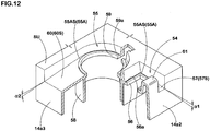
- the compressor device 2 has on one outsi de surface 14a1 an approximately semicircular recei vi ng depression 53 that follows the outer shape of the bottle unit 3 and allows the bottle unit 3 to be stably seated therein.
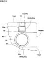
- the storage case 9 has on an upper surface SU (hereinafter, referred to as a case upper surface SU) thereof a switch mounting depression 54 for mounting the power switch SW and a pressure gauge mounting depression 55 for mounting the pressure gauge 22.
- the power switch SW is mounted at a bottom portion 54A of the switch mounting depression 54, at a distance H1 of 3 to 15 mm from the case upper surface SU toward the lower side.
- the pressure gauge 22 is mounted at a bottom portion 55A of the pressure gauge mounting depression 55, at a distance H2 of 3 to 15 mm from the upper surface SU toward the lower side.
- the power switch sw may have a well-known structure with an operation portion SWa for ON/OFF operations at an upper part thereof, such as a seesaw switch, for example.
- the switch mounti ng depressi on 54 has at a bottom portion 54A thereof a mounti ng hole 56 for mounting the power switch sw from above.
- a surroundi ng rib 56a protruding from the bottom porti on upper surface 54AS with a small height of about 0.5 to 1.0 mm, for example, thereby suppressing invasion of rainwater or the like into the hole 56.
- drainage channels 57 Formed on the case upper surface SU are drainage channels 57 extending from the mounting depression 54 at a downward incline toward an outer wall surface 14a2 of the storage case closest to the mounting depression 54.
- a plurality of, for example, two drainage channels 57 are disposed.
- a block-like rising portion 61 sandwiched between the drainage channels 57 and 57 and having the same height as that of the case upper surface SU is formed between the power switch SW and the outer wall surface 14a2.
- the drainage channels 57 each have a channel bottom surface 57S that is connected smoothly to the bottom portion upper surface 54AS and is inclined downward at an angle ⁇ 1 of 0.3 to 3.0° with respect to a horizontal surface.
- the bottom portion upper surface 54AS may be horizontal, but is preferably inclined in the same manner as the drainage channels 57.
- the pressure gauge 22 may have a well-known structure with a display portion 22a on an upper part thereof.
- the pressure gauge mounting depression 55 has an annular rib 58 projecting from a lower surface of a bottom portion 55A.
- the pressure gauge 22 is mounted from below between the lower surface and an inner peripheral surface of the annular rib 58.
- the bottom portion 55A has on an inside of the annular rib 58 a window hole 59 for exposure of the display portion 22a.
- a surrounding rib 59a protruding with a small height of about 0.5 to 1.0 mm, for example, from the bottom portion upper surface 55AS, thereby suppressing invasion of rainwater or the like into the hole 59.
- a drainage channel 60 Formed on the case upper surface SU is a drainage channel 60 extending at a downward incline from the mounting depression 55 toward an outer wall surface 14a3 of the storage case closest to the mounting depression 55.
- one wide drainage channel 60 with approximately the same width as that of the mounting depression 55, is disposed.
- the drainage channel 60 also has a channel bottom surface 60S that is connected smoothly to the bottom portion upper surface 55AS and is inclined downward at an angle ⁇ 2 of 0.3 to 3.0° with respect to the horizontal surface.
- the bottom portion upper surface 55AS may be horizontal, but is preferably inclined in the same manner as the drainage channel 60.
- the power switch sw and the pressure gauge 22 are mounted at the distances H1 and H2 of 3 to 15 mm from the case upper surface su toward the lower side. Therefore, even if the compressor device 2 is fallen down by mistake during a connection operation at a site of puncture repair, it is possible to prevent the power switch sw and the pressure gauge 22 from being broken due to direct collision against the ground.
- the rising portion 61 is disposed between the power switch sw and the outer wall surface 14a2, thereby making it possible to protect the power switch sw as an important component in a more reliable manner.
- the drainage channels 57 and 60 are formed on the case upper surface SU so as to extend at a downward incline from the mounting depressions 54 and 55 toward the outer wall surfaces 14a2 and 14a3, it is possible to prevent an electric failure resulting from rainwater because, even when being used in the rain, rainwater does not pile up in the mounting depressions 54 and 55.
- the lower limit for the distances H1 and H2 is preferably 5 mm or more, and the upper limit for the same is preferably 10 mm or less.
- the feeding hose 29 is connected to the sealant/compressed air retrieval opening portion 7. when being not in use, the feeding hose 29 is stored in a state of bei ng wound around the wai st porti on 33 as shown in Fig. 14 .
- the bottle unit 3 has at the boss portion 32B an inner stopper 52 for closing the air flow path upper opening 37 and the sealant/compressed air retrieval flow path upper opening 38, as shown by alternate long and short dash lines in Fig. 8 , so as to prevent outflow of the puncture sealant from the bottle container 4 when the bottle unit 3 is not in use.
- the inner stopper 52 can be removed from the boss portion 32B due to pressure rise by compressed air from the compressor device 2.
- the compressed air discharge opening portion 8 may be formed as the connection nozzle 41
- the air intake opening portion 27 may be formed as the nozzle receiver 28.
Landscapes
- Engineering & Computer Science (AREA)
- Mechanical Engineering (AREA)
- Vehicle Cleaning, Maintenance, Repair, Refitting, And Outriggers (AREA)
Claims (4)
- Kit de réparation pour crevaison (1), comprenant :un dispositif compresseur (2), incluant un commutateur de puissance (SW), et un corps principal de compresseur (13) qui est entraîné par le commutateur de puissance (SW) et génère de l'air comprimé, stocké dans un casier de stockage en forme de boîte rectangulaire ; etune unité en bouteille (3), incluant un conteneur en bouteille (4) contenant un produit d'étanchement de crevaison et un capuchon (6) attaché sur une portion d'ouverture du conteneur en bouteille (4), dans lequelle dispositif compresseur (2) inclut une portion d'ouverture de décharge d'air comprimé (8) pour décharger de l'air comprimé,
le capuchon (6) est pourvu d'une portion d'ouverture d'admission d'air (27) pour alimenter l'air comprimé provenant de la portion d'ouverture de décharge d'air comprimé (8) jusque dans le conteneur en bouteille (4), et une portion d'ouverture de récupération de produit d'étanchement de crevaison/d'air comprimé (7) pour récupérer en séquence le produit d'étanchement de crevaison et l'air comprimé hors du conteneur en bouteille (4) par l'alimentation d'air comprimé,
une portion parmi la portion d'ouverture de décharge d'air comprimé (8) et la portion d'ouverture d'admission d'air (27) inclut une buse de connexion (41) qui se projette vers l'autre dans une direction d'avance,
et l'autre inclut un récepteur de buse (28) dans lequel la buse de connexion (41) est insérée et engagée, ce qui permet une connexion directe du dispositif compresseur (2) et de l'unité à bouteille (3),
caractérisé en ce que
le dispositif compresseur (2) inclut une jauge de pression (22) qui mesure une pression de l'air comprimé venant du corps principal de compresseur (13), stocké dans un casier de stockage en forme de boîte rectangulaire (9),
le capuchon (6) inclut une portion en plaque de fond (31) constituant une surface de fond (6S), une portion de montage de bouteille (32) pour monter la portion d'ouverture (5) du conteneur en bouteille (4), et une portion de taille rétrécie (33) disposée entre la portion en plaque de fond (31) et la portion de montage de bouteille (32),
la portion de taille (33) est dotée de la portion d'ouverture d'admission d'air (27) et de la portion d'ouverture de récupération de produit d'étanchement de crevaison/d'air comprimé (7),
le casier de stockage (9) possède sur sa surface supérieure (SU) une dépression de montage de commutateur (54) pour monter le commutateur de puissance (SW) et une dépression de montage de jauge de pression (55) pour monter la jauge de pression (22), le commutateur de puissance (SW) et la jauge de pression (22) étant montés sur des portions de fond des dépressions de montage respectives (54, 55) à une distance de 3 à 15 mm vers le bas depuis la surface supérieure (SU), et
des canaux de drainage (57, 60) sont formés sur la surface supérieure (SU) de manière à s'étendre suivant une inclinaison descendante depuis les dépressions de montage (54, 55) vers les surfaces latérales extérieures du casier de stockage (9). - Kit de réparation pour crevaison selon la revendication 1, dans lequel le canal de drainage (57, 60) présente une surface de fond de canal (57S, 60S) inclinée vers le bas sous un angle (α1, α2) de 0,3 à 3,0° par rapport à une surface horizontale.
- Kit de réparation pour crevaison selon la revendication 1 ou 2, dans lequel
le corps principal de compresseur (13) inclut un moteur (M) ; un piston (10) connecté au moteur (M) via un mécanisme à manivelle (17) ; et un cylindre (12) qui abrite le piston (10) de manière à effectuer un va-et-vient et forme une chambre de pompe (11) pour comprimer l'air entre le cylindre (12) et le piston (10), et
le cylindre (12) inclut de façon intégrale la portion d'ouverture de décharge d'air comprimé (8), et la portion d'ouverture de décharge d'air comprimé (8) est formée par le récepteur de buse (28). - Kit de réparation pour crevaison selon l'une quelconque des revendications 1 à 3, dans lequel
dans l'état de connexion directe, une surface de fond (2S) du dispositif compresseur (2) et une surface de fond (6S) du capuchon (6) sont en affleurement l'une avec l'autre.
Applications Claiming Priority (1)
| Application Number | Priority Date | Filing Date | Title |
|---|---|---|---|
| PCT/JP2009/068813 WO2011055422A1 (fr) | 2009-11-04 | 2009-11-04 | Kit de réparation pour crevaison |
Publications (3)
| Publication Number | Publication Date |
|---|---|
| EP2497627A1 EP2497627A1 (fr) | 2012-09-12 |
| EP2497627A4 EP2497627A4 (fr) | 2014-04-30 |
| EP2497627B1 true EP2497627B1 (fr) | 2017-03-01 |
Family
ID=43969667
Family Applications (1)
| Application Number | Title | Priority Date | Filing Date |
|---|---|---|---|
| EP09851076.1A Active EP2497627B1 (fr) | 2009-11-04 | 2009-11-04 | Kit de réparation pour crevaison |
Country Status (4)
| Country | Link |
|---|---|
| EP (1) | EP2497627B1 (fr) |
| JP (1) | JP5364171B2 (fr) |
| CN (1) | CN102686384B (fr) |
| WO (1) | WO2011055422A1 (fr) |
Cited By (1)
| Publication number | Priority date | Publication date | Assignee | Title |
|---|---|---|---|---|
| US11135792B2 (en) | 2017-09-25 | 2021-10-05 | Active Tools International (Hk) Ltd. | Tire repairing system |
Families Citing this family (5)
| Publication number | Priority date | Publication date | Assignee | Title |
|---|---|---|---|---|
| TWM462676U (zh) * | 2013-05-03 | 2013-10-01 | 冠翔(香港)工業有限公司 | 輪胎修補機的快速連接分離裝置 |
| US20170173900A1 (en) * | 2014-02-06 | 2017-06-22 | Sumitomo Rubber Industries, Ltd. | Puncture repair kit |
| TWI647129B (zh) * | 2015-04-23 | 2019-01-11 | 周文三 | 空氣壓縮機裝置 |
| US10753351B2 (en) | 2015-09-02 | 2020-08-25 | Active Tools International (Hk) Ltd. | Air inflating device and tire repair machine comprising same |
| DE102024203322A1 (de) * | 2024-04-11 | 2025-10-16 | Continental Reifen Deutschland Gmbh | Pannenhilfesystem |
Citations (1)
| Publication number | Priority date | Publication date | Assignee | Title |
|---|---|---|---|---|
| DE19846451A1 (de) * | 1998-10-08 | 2000-04-13 | Sumitomo Rubber Ind | Abdichtvorrichtung |
Family Cites Families (7)
| Publication number | Priority date | Publication date | Assignee | Title |
|---|---|---|---|---|
| DE20115003U1 (de) * | 2001-09-11 | 2003-02-06 | Dunlop GmbH, 63450 Hanau | Abdichtsystem |
| JP4392292B2 (ja) * | 2004-06-01 | 2009-12-24 | 住友ゴム工業株式会社 | 小型簡易コンプレッサ装置 |
| DE102004060662A1 (de) * | 2004-12-15 | 2006-07-06 | Continental Aktiengesellschaft | Sytem zum Abdichten aufblasbarer Gegenstände, insbesondere Reifen |
| JP2008307861A (ja) * | 2007-06-18 | 2008-12-25 | Bridgestone Corp | シーリング・ポンプアップ装置 |
| DE202007016242U1 (de) * | 2007-11-21 | 2008-01-31 | Continental Aktiengesellschaft | Vorrichtung mit einer Schaltmarkierung zum Abdichten und Aufpumpen aufblasbarer Gegenstände |
| JP4705655B2 (ja) * | 2008-03-25 | 2011-06-22 | 住友ゴム工業株式会社 | タイヤの一体型パンク修理装置 |
| JP4914394B2 (ja) * | 2008-03-25 | 2012-04-11 | 住友ゴム工業株式会社 | タイヤのパンク修理装置 |
-
2009
- 2009-11-04 CN CN200980162256.XA patent/CN102686384B/zh active Active
- 2009-11-04 JP JP2011539212A patent/JP5364171B2/ja active Active
- 2009-11-04 WO PCT/JP2009/068813 patent/WO2011055422A1/fr not_active Ceased
- 2009-11-04 EP EP09851076.1A patent/EP2497627B1/fr active Active
Patent Citations (1)
| Publication number | Priority date | Publication date | Assignee | Title |
|---|---|---|---|---|
| DE19846451A1 (de) * | 1998-10-08 | 2000-04-13 | Sumitomo Rubber Ind | Abdichtvorrichtung |
Cited By (1)
| Publication number | Priority date | Publication date | Assignee | Title |
|---|---|---|---|---|
| US11135792B2 (en) | 2017-09-25 | 2021-10-05 | Active Tools International (Hk) Ltd. | Tire repairing system |
Also Published As
| Publication number | Publication date |
|---|---|
| JPWO2011055422A1 (ja) | 2013-03-21 |
| EP2497627A4 (fr) | 2014-04-30 |
| WO2011055422A1 (fr) | 2011-05-12 |
| CN102686384B (zh) | 2014-08-06 |
| JP5364171B2 (ja) | 2013-12-11 |
| EP2497627A1 (fr) | 2012-09-12 |
| CN102686384A (zh) | 2012-09-19 |
Similar Documents
| Publication | Publication Date | Title |
|---|---|---|
| EP2497627B1 (fr) | Kit de réparation pour crevaison | |
| EP2497628B1 (fr) | Kit de réparation pour crevaison | |
| KR101814217B1 (ko) | 펑크 수리 킷 | |
| EP2960502B1 (fr) | Compresseur d'air portable | |
| JP5054627B2 (ja) | シーリング剤容器の蓋ユニット | |
| JP5357703B2 (ja) | パンク修理キット | |
| JP5357704B2 (ja) | パンク修理キット | |
| JP5374319B2 (ja) | パンク修理キット | |
| CN107225779A (zh) | 漏气修理用的盖单元 | |
| JP5416550B2 (ja) | パンク修理キット | |
| JP2010234795A (ja) | シーリング・ポンプアップ装置 | |
| JP2012006346A (ja) | キャップユニット | |
| JP5421734B2 (ja) | パンク修理キット | |
| JP2011098458A (ja) | パンク修理キット | |
| JP2012006347A (ja) | パンク修理キットの接続方法 | |
| JP5357702B2 (ja) | パンク修理キット | |
| JP5227354B2 (ja) | キャップユニット | |
| CN118082657A (zh) | 箱体结构及具有其的车辆 | |
| JP2012051337A (ja) | シーリング・ポンプアップ装置 | |
| JP2008162060A (ja) | タイヤのシーリング・ポンプアップ装置 | |
| JP2007090575A (ja) | タイヤのパンク修理装置 |
Legal Events
| Date | Code | Title | Description |
|---|---|---|---|
| PUAI | Public reference made under article 153(3) epc to a published international application that has entered the european phase |
Free format text: ORIGINAL CODE: 0009012 |
|
| 17P | Request for examination filed |
Effective date: 20120426 |
|
| AK | Designated contracting states |
Kind code of ref document: A1 Designated state(s): AT BE BG CH CY CZ DE DK EE ES FI FR GB GR HR HU IE IS IT LI LT LU LV MC MK MT NL NO PL PT RO SE SI SK SM TR |
|
| DAX | Request for extension of the european patent (deleted) | ||
| A4 | Supplementary search report drawn up and despatched |
Effective date: 20140328 |
|
| RIC1 | Information provided on ipc code assigned before grant |
Ipc: B60S 5/04 20060101ALI20140324BHEP Ipc: B29C 73/16 20060101AFI20140324BHEP |
|
| 17Q | First examination report despatched |
Effective date: 20150612 |
|
| REG | Reference to a national code |
Ref country code: DE Ref legal event code: R079 Ref document number: 602009044572 Country of ref document: DE Free format text: PREVIOUS MAIN CLASS: B29C0073020000 Ipc: B29C0073160000 |
|
| GRAP | Despatch of communication of intention to grant a patent |
Free format text: ORIGINAL CODE: EPIDOSNIGR1 |
|
| RIC1 | Information provided on ipc code assigned before grant |
Ipc: B60S 5/04 20060101ALI20160818BHEP Ipc: B29L 30/00 20060101ALN20160818BHEP Ipc: B29C 73/16 20060101AFI20160818BHEP |
|
| RIC1 | Information provided on ipc code assigned before grant |
Ipc: B29C 73/16 20060101AFI20160824BHEP Ipc: B29L 30/00 20060101ALN20160824BHEP Ipc: B60S 5/04 20060101ALI20160824BHEP |
|
| INTG | Intention to grant announced |
Effective date: 20160905 |
|
| STAA | Information on the status of an ep patent application or granted ep patent |
Free format text: STATUS: GRANT OF PATENT IS INTENDED |
|
| GRAS | Grant fee paid |
Free format text: ORIGINAL CODE: EPIDOSNIGR3 |
|
| GRAA | (expected) grant |
Free format text: ORIGINAL CODE: 0009210 |
|
| STAA | Information on the status of an ep patent application or granted ep patent |
Free format text: STATUS: THE PATENT HAS BEEN GRANTED |
|
| AK | Designated contracting states |
Kind code of ref document: B1 Designated state(s): AT BE BG CH CY CZ DE DK EE ES FI FR GB GR HR HU IE IS IT LI LT LU LV MC MK MT NL NO PL PT RO SE SI SK SM TR |
|
| REG | Reference to a national code |
Ref country code: GB Ref legal event code: FG4D |
|
| REG | Reference to a national code |
Ref country code: CH Ref legal event code: EP Ref country code: AT Ref legal event code: REF Ref document number: 870772 Country of ref document: AT Kind code of ref document: T Effective date: 20170315 |
|
| REG | Reference to a national code |
Ref country code: IE Ref legal event code: FG4D |
|
| REG | Reference to a national code |
Ref country code: DE Ref legal event code: R096 Ref document number: 602009044572 Country of ref document: DE |
|
| REG | Reference to a national code |
Ref country code: NL Ref legal event code: MP Effective date: 20170301 |
|
| REG | Reference to a national code |
Ref country code: LT Ref legal event code: MG4D |
|
| REG | Reference to a national code |
Ref country code: AT Ref legal event code: MK05 Ref document number: 870772 Country of ref document: AT Kind code of ref document: T Effective date: 20170301 |
|
| PG25 | Lapsed in a contracting state [announced via postgrant information from national office to epo] |
Ref country code: LT Free format text: LAPSE BECAUSE OF FAILURE TO SUBMIT A TRANSLATION OF THE DESCRIPTION OR TO PAY THE FEE WITHIN THE PRESCRIBED TIME-LIMIT Effective date: 20170301 Ref country code: GR Free format text: LAPSE BECAUSE OF FAILURE TO SUBMIT A TRANSLATION OF THE DESCRIPTION OR TO PAY THE FEE WITHIN THE PRESCRIBED TIME-LIMIT Effective date: 20170602 Ref country code: HR Free format text: LAPSE BECAUSE OF FAILURE TO SUBMIT A TRANSLATION OF THE DESCRIPTION OR TO PAY THE FEE WITHIN THE PRESCRIBED TIME-LIMIT Effective date: 20170301 Ref country code: NO Free format text: LAPSE BECAUSE OF FAILURE TO SUBMIT A TRANSLATION OF THE DESCRIPTION OR TO PAY THE FEE WITHIN THE PRESCRIBED TIME-LIMIT Effective date: 20170601 Ref country code: FI Free format text: LAPSE BECAUSE OF FAILURE TO SUBMIT A TRANSLATION OF THE DESCRIPTION OR TO PAY THE FEE WITHIN THE PRESCRIBED TIME-LIMIT Effective date: 20170301 |
|
| PG25 | Lapsed in a contracting state [announced via postgrant information from national office to epo] |
Ref country code: LV Free format text: LAPSE BECAUSE OF FAILURE TO SUBMIT A TRANSLATION OF THE DESCRIPTION OR TO PAY THE FEE WITHIN THE PRESCRIBED TIME-LIMIT Effective date: 20170301 Ref country code: BG Free format text: LAPSE BECAUSE OF FAILURE TO SUBMIT A TRANSLATION OF THE DESCRIPTION OR TO PAY THE FEE WITHIN THE PRESCRIBED TIME-LIMIT Effective date: 20170601 Ref country code: ES Free format text: LAPSE BECAUSE OF FAILURE TO SUBMIT A TRANSLATION OF THE DESCRIPTION OR TO PAY THE FEE WITHIN THE PRESCRIBED TIME-LIMIT Effective date: 20170301 Ref country code: AT Free format text: LAPSE BECAUSE OF FAILURE TO SUBMIT A TRANSLATION OF THE DESCRIPTION OR TO PAY THE FEE WITHIN THE PRESCRIBED TIME-LIMIT Effective date: 20170301 Ref country code: SE Free format text: LAPSE BECAUSE OF FAILURE TO SUBMIT A TRANSLATION OF THE DESCRIPTION OR TO PAY THE FEE WITHIN THE PRESCRIBED TIME-LIMIT Effective date: 20170301 |
|
| PG25 | Lapsed in a contracting state [announced via postgrant information from national office to epo] |
Ref country code: NL Free format text: LAPSE BECAUSE OF FAILURE TO SUBMIT A TRANSLATION OF THE DESCRIPTION OR TO PAY THE FEE WITHIN THE PRESCRIBED TIME-LIMIT Effective date: 20170301 |
|
| PG25 | Lapsed in a contracting state [announced via postgrant information from national office to epo] |
Ref country code: RO Free format text: LAPSE BECAUSE OF FAILURE TO SUBMIT A TRANSLATION OF THE DESCRIPTION OR TO PAY THE FEE WITHIN THE PRESCRIBED TIME-LIMIT Effective date: 20170301 Ref country code: SK Free format text: LAPSE BECAUSE OF FAILURE TO SUBMIT A TRANSLATION OF THE DESCRIPTION OR TO PAY THE FEE WITHIN THE PRESCRIBED TIME-LIMIT Effective date: 20170301 Ref country code: IT Free format text: LAPSE BECAUSE OF FAILURE TO SUBMIT A TRANSLATION OF THE DESCRIPTION OR TO PAY THE FEE WITHIN THE PRESCRIBED TIME-LIMIT Effective date: 20170301 Ref country code: EE Free format text: LAPSE BECAUSE OF FAILURE TO SUBMIT A TRANSLATION OF THE DESCRIPTION OR TO PAY THE FEE WITHIN THE PRESCRIBED TIME-LIMIT Effective date: 20170301 Ref country code: CZ Free format text: LAPSE BECAUSE OF FAILURE TO SUBMIT A TRANSLATION OF THE DESCRIPTION OR TO PAY THE FEE WITHIN THE PRESCRIBED TIME-LIMIT Effective date: 20170301 |
|
| PG25 | Lapsed in a contracting state [announced via postgrant information from national office to epo] |
Ref country code: PL Free format text: LAPSE BECAUSE OF FAILURE TO SUBMIT A TRANSLATION OF THE DESCRIPTION OR TO PAY THE FEE WITHIN THE PRESCRIBED TIME-LIMIT Effective date: 20170301 Ref country code: IS Free format text: LAPSE BECAUSE OF FAILURE TO SUBMIT A TRANSLATION OF THE DESCRIPTION OR TO PAY THE FEE WITHIN THE PRESCRIBED TIME-LIMIT Effective date: 20170701 Ref country code: SM Free format text: LAPSE BECAUSE OF FAILURE TO SUBMIT A TRANSLATION OF THE DESCRIPTION OR TO PAY THE FEE WITHIN THE PRESCRIBED TIME-LIMIT Effective date: 20170301 Ref country code: PT Free format text: LAPSE BECAUSE OF FAILURE TO SUBMIT A TRANSLATION OF THE DESCRIPTION OR TO PAY THE FEE WITHIN THE PRESCRIBED TIME-LIMIT Effective date: 20170703 |
|
| REG | Reference to a national code |
Ref country code: DE Ref legal event code: R097 Ref document number: 602009044572 Country of ref document: DE |
|
| PLBE | No opposition filed within time limit |
Free format text: ORIGINAL CODE: 0009261 |
|
| STAA | Information on the status of an ep patent application or granted ep patent |
Free format text: STATUS: NO OPPOSITION FILED WITHIN TIME LIMIT |
|
| PG25 | Lapsed in a contracting state [announced via postgrant information from national office to epo] |
Ref country code: DK Free format text: LAPSE BECAUSE OF FAILURE TO SUBMIT A TRANSLATION OF THE DESCRIPTION OR TO PAY THE FEE WITHIN THE PRESCRIBED TIME-LIMIT Effective date: 20170301 |
|
| 26N | No opposition filed |
Effective date: 20171204 |
|
| PG25 | Lapsed in a contracting state [announced via postgrant information from national office to epo] |
Ref country code: SI Free format text: LAPSE BECAUSE OF FAILURE TO SUBMIT A TRANSLATION OF THE DESCRIPTION OR TO PAY THE FEE WITHIN THE PRESCRIBED TIME-LIMIT Effective date: 20170301 |
|
| PG25 | Lapsed in a contracting state [announced via postgrant information from national office to epo] |
Ref country code: MC Free format text: LAPSE BECAUSE OF FAILURE TO SUBMIT A TRANSLATION OF THE DESCRIPTION OR TO PAY THE FEE WITHIN THE PRESCRIBED TIME-LIMIT Effective date: 20170301 |
|
| GBPC | Gb: european patent ceased through non-payment of renewal fee |
Effective date: 20171104 |
|
| PG25 | Lapsed in a contracting state [announced via postgrant information from national office to epo] |
Ref country code: CH Free format text: LAPSE BECAUSE OF NON-PAYMENT OF DUE FEES Effective date: 20171130 Ref country code: LI Free format text: LAPSE BECAUSE OF NON-PAYMENT OF DUE FEES Effective date: 20171130 |
|
| PG25 | Lapsed in a contracting state [announced via postgrant information from national office to epo] |
Ref country code: LU Free format text: LAPSE BECAUSE OF NON-PAYMENT OF DUE FEES Effective date: 20171104 |
|
| REG | Reference to a national code |
Ref country code: FR Ref legal event code: ST Effective date: 20180731 Ref country code: BE Ref legal event code: MM Effective date: 20171130 |
|
| REG | Reference to a national code |
Ref country code: IE Ref legal event code: MM4A |
|
| PG25 | Lapsed in a contracting state [announced via postgrant information from national office to epo] |
Ref country code: MT Free format text: LAPSE BECAUSE OF NON-PAYMENT OF DUE FEES Effective date: 20171104 |
|
| PG25 | Lapsed in a contracting state [announced via postgrant information from national office to epo] |
Ref country code: IE Free format text: LAPSE BECAUSE OF NON-PAYMENT OF DUE FEES Effective date: 20171104 Ref country code: FR Free format text: LAPSE BECAUSE OF NON-PAYMENT OF DUE FEES Effective date: 20171130 |
|
| PG25 | Lapsed in a contracting state [announced via postgrant information from national office to epo] |
Ref country code: GB Free format text: LAPSE BECAUSE OF NON-PAYMENT OF DUE FEES Effective date: 20171104 Ref country code: BE Free format text: LAPSE BECAUSE OF NON-PAYMENT OF DUE FEES Effective date: 20171130 |
|
| PG25 | Lapsed in a contracting state [announced via postgrant information from national office to epo] |
Ref country code: HU Free format text: LAPSE BECAUSE OF FAILURE TO SUBMIT A TRANSLATION OF THE DESCRIPTION OR TO PAY THE FEE WITHIN THE PRESCRIBED TIME-LIMIT; INVALID AB INITIO Effective date: 20091104 |
|
| PG25 | Lapsed in a contracting state [announced via postgrant information from national office to epo] |
Ref country code: CY Free format text: LAPSE BECAUSE OF NON-PAYMENT OF DUE FEES Effective date: 20170301 |
|
| PG25 | Lapsed in a contracting state [announced via postgrant information from national office to epo] |
Ref country code: MK Free format text: LAPSE BECAUSE OF FAILURE TO SUBMIT A TRANSLATION OF THE DESCRIPTION OR TO PAY THE FEE WITHIN THE PRESCRIBED TIME-LIMIT Effective date: 20170301 |
|
| PG25 | Lapsed in a contracting state [announced via postgrant information from national office to epo] |
Ref country code: TR Free format text: LAPSE BECAUSE OF FAILURE TO SUBMIT A TRANSLATION OF THE DESCRIPTION OR TO PAY THE FEE WITHIN THE PRESCRIBED TIME-LIMIT Effective date: 20170301 |
|
| P01 | Opt-out of the competence of the unified patent court (upc) registered |
Free format text: CASE NUMBER: UPC_APP_117595/2023 Effective date: 20230510 |
|
| PGFP | Annual fee paid to national office [announced via postgrant information from national office to epo] |
Ref country code: DE Payment date: 20250930 Year of fee payment: 17 |