EP2497632A2 - Antriebseinheit für einen Stanzautomat oder eine Presse - Google Patents
Antriebseinheit für einen Stanzautomat oder eine Presse Download PDFInfo
- Publication number
- EP2497632A2 EP2497632A2 EP20120001444 EP12001444A EP2497632A2 EP 2497632 A2 EP2497632 A2 EP 2497632A2 EP 20120001444 EP20120001444 EP 20120001444 EP 12001444 A EP12001444 A EP 12001444A EP 2497632 A2 EP2497632 A2 EP 2497632A2
- Authority
- EP
- European Patent Office
- Prior art keywords
- rotor
- drive unit
- press
- output shaft
- stator
- Prior art date
- Legal status (The legal status is an assumption and is not a legal conclusion. Google has not performed a legal analysis and makes no representation as to the accuracy of the status listed.)
- Granted
Links
Images

Classifications
-
- B—PERFORMING OPERATIONS; TRANSPORTING
- B30—PRESSES
- B30B—PRESSES IN GENERAL
- B30B1/00—Presses, using a press ram, characterised by the features of the drive therefor, pressure being transmitted directly, or through simple thrust or tension members only, to the press ram or platen
- B30B1/26—Presses, using a press ram, characterised by the features of the drive therefor, pressure being transmitted directly, or through simple thrust or tension members only, to the press ram or platen by cams, eccentrics, or cranks
- B30B1/266—Drive systems for the cam, eccentric or crank axis
-
- B—PERFORMING OPERATIONS; TRANSPORTING
- B21—MECHANICAL METAL-WORKING WITHOUT ESSENTIALLY REMOVING MATERIAL; PUNCHING METAL
- B21J—FORGING; HAMMERING; PRESSING METAL; RIVETING; FORGE FURNACES
- B21J9/00—Forging presses
- B21J9/10—Drives for forging presses
- B21J9/18—Drives for forging presses operated by making use of gearing mechanisms, e.g. levers, spindles, crankshafts, eccentrics, toggle-levers, rack bars
-
- H—ELECTRICITY
- H02—GENERATION; CONVERSION OR DISTRIBUTION OF ELECTRIC POWER
- H02K—DYNAMO-ELECTRIC MACHINES
- H02K7/00—Arrangements for handling mechanical energy structurally associated with dynamo-electric machines, e.g. structural association with mechanical driving motors or auxiliary dynamo-electric machines
- H02K7/14—Structural association with mechanical loads, e.g. with hand-held machine tools or fans
Definitions
- the subject of this invention is a drive unit for a stamping press or a press for moving a plunger with at least one electric motor having a stator and a rotor, which are arranged concentrically with each other, wherein the stator is rotatably connected to the press frame and an output shaft for moving of the plunger is driven by the rotor.
- Actuators for the ram of stamping presses or presses are well known, these are usually spindle, eccentric or hydraulic drives. There are also embodiments with an eccentric - direct drive known. That's how it describes DE 10 2009 029 921 A1 a direct press drive with at least one electric motor, which includes a stator and a rotor, which are arranged concentrically with each other.
- this drive comprises an eccentric, which is designed as part of the rotor and is rotatably mounted together with the rotor.
- the press ram is driven by a connecting rod, which is mounted on the eccentric.
- a punching or forming tool is arranged, through which the workpiece processed, for example, punched or formed, is.
- the electric motor must apply a very large torque.
- the torque is influenced on the one hand by the width of the electric motor (viewed in the direction of the rotor axis) and on the other hand by the diameter of the rotor.
- the torque increases linearly with increasing width of the motor, whereas the torque rises quadratically with increasing radius of the rotor. Therefore, to obtain appropriate torques, the motor must be quite large in diameter.
- the aim of the invention is to reduce the diameter of the direct drive.
- This object is achieved by a novel drive unit for a stamping press or a press, in which between the rotor and the Output shaft is arranged a towing crank.
- the towing crank causes an additional translation.
- the electric motor can be made more compact, it is cheaper to manufacture and more energy efficient, since with the same maximum torque smaller electrical connection power than the direct drive in the DE 10 2009 029 921 A1 is necessary.
- the use of a towing crank also offers the advantage that different torques can be achieved with the same electric motor diameter by changing the towing crank geometry.
- a fixed movement curve is predetermined by the drag crank drive which can be changed by the electric motor, which is preferably designed as a segment motor or as a servomotor.
- the towing crank is disposed within the rotor. This results in a particularly compact design.
- the rotor consists of several rotor segments and if the rotor segments are permanent magnets.
- the axis of the output shaft is arranged eccentrically to the rotor axis.
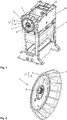
- FIG. 1 an embodiment of the drive unit according to the invention is shown. It shows a press frame 1 with the drive according to the invention 2.
- the drive unit 2 consists essentially of an electric motor 17, an output shaft 8 and a towing crank 5.
- the electric motor 17 consists of a stator 4 and a rotor 6, which are arranged concentrically to one another are.
- the stator 4 is rotatably connected via the stator housing 3 to the press head piece 16.
- the rotor 6 is rotatably mounted within the stator 4. The power transmission from the rotor 6 to the output shaft 8 via a towing crank. 5
- FIG. 2 a detail view of the press drive 2 is shown.
- Fig. 3 shows a sectional view through the drive unit 2 from Fig. 2 .
- the towing crank 5 consists of a connecting rod 9 and of the crankshaft 10.
- the connecting rod 9 is rotatably connected at one end via the connecting rod 11 with the rotor 6.
- the connecting rod 9 is rotatably connected to the crankshaft 10 via the bearing 12.
- the crankshaft 10 is non-rotatably mounted on the output shaft. 8
- the geometry of the towing crank is determined by the sizes A, B, C and D.
- the size A is the distance between the axes of rotation between the connecting rod bearing 11 and the bearing 12.
- the size B denotes the distance between the axes of rotation of the bearing 12 and the output shaft 8.
- the size C denotes the distance between the axes of rotation of the connecting rod bearing 11 and the rotor 6.
- the size D is a measure of the eccentricity of the towing crank and denotes the distance between the axes of rotation of the rotor 6 and the output shaft. 8 Due to the geometry of the towing crank 5, the course of the torque curve on the output shaft 8 is influenced. By changing the sizes A, B, C or D, the course of the torque curve can be influenced and optimized for the respective application while maintaining the same type of electric motor.
- the rotor is rotatably supported by the rotor bearing 7 in the stator housing 3 or in the press head piece 16.
- the rotor 6 and the stator 4 are constructed in the present example of rotor segments 14 and stator segments 15.
- the rotor 6 In operation, the rotor 6 is rotated by the electromagnetic forces between the stator 4 and the rotor 6.
- the rotor 6 transmits via the towing crank 5, ie via the connecting rod 9 and the crankshaft 10, a torque on the output shaft 8.
- the output shaft 8 itself is via an output shaft bearing 13 (see Fig. 1 ) stored in the press head piece 16.
- the power transmission from the output shaft 8 to the plunger in a conventional manner. So for example via an eccentric, which is arranged on the output shaft 8 and a connecting rod, which is mounted on the eccentric.
- the connecting rod then drives the plunger. But it is also conceivable that between the output shaft 8 and the plunger, a further transmission is arranged.
Landscapes
- Engineering & Computer Science (AREA)
- Mechanical Engineering (AREA)
- Power Engineering (AREA)
- Press Drives And Press Lines (AREA)
- Control Of Presses (AREA)
Abstract
Description
- Den Gegenstand dieser Erfindung bildet eine Antriebseinheit für einen Stanzautomat oder eine Presse zum Bewegen eines Stößels mit mindestens einem Elektromotor, der einen Stator und einen Rotor aufweist, die konzentrisch zueinander angeordnet sind, wobei der Stator drehfest mit dem Pressengestell verbunden ist und eine Abtriebswelle zum Bewegen des Stößels durch den Rotor antreibbar ist.
- Antriebe für den Stößel von Stanzautomaten oder Pressen sind hinlänglich bekannt, es handelt sich dabei meist um Spindel-, Exzenter- oder hydraulische Antriebe. Es sind auch Ausführungsformen mit einem Exzenterpressen - Direktantrieb bekannt. So beschreibt die
DE 10 2009 029 921 A1 einen Pressendirektantrieb mit zumindest einem Elektromotor, zu dem ein Stator und ein Rotor gehören, die konzentrisch zueinander angeordnet sind. Außerdem umfasst dieser Antrieb einen Exzenter, der als Bestandteil des Rotors ausgebildet ist und mit dem Rotor gemeinsam drehbar gelagert ist. Der Pressenstößel wird dabei über ein Pleuel, das auf dem Exzenter gelagert ist, angetrieben.
Am Stößel ist ein Stanz- oder Umformwerkzeug angeordnet, durch das das Werkstück bearbeitet, zum Beispiel gestanzt oder umgeformt, wird. Für diesen Bearbeitungsvorgang ist eine erhebliche Presskraft des Stößels erforderlich. Bei einer direkten Koppelung des Direktantriebes mit dem Exzenter, wie dies in derDE 10 2009 029 921 A1 beschrieben ist, muss der Elektromotor ein sehr großes Drehmoment aufbringen. Das Drehmoment wird einerseits durch die Breite des Elektromotors (in Richtung der Rotorachse betrachtet) und andererseits durch den Durchmesser des Rotors beeinflusst. Dabei steigt das Drehmoment mit zunehmender Breite des Motors linear an, wohingegen das Drehmoment mit steigendem Radius des Rotor quadratisch ansteigt. Um entsprechende Drehmomente zu erhalten, muss daher der Motor ziemlich groß im Durchmesser sein. - Ziel der Erfindung ist es, den Durchmesser des Direktantriebes zu verkleinern. Gelöst wird diese Aufgabe durch eine neuartige Antriebseinheit für einen Stanzautomaten oder eine Presse, bei der zwischen dem Rotor und der Abtriebswelle eine Schleppkurbel angeordnet ist. Durch die Schleppkurbel kommt es zu einer zusätzlichen Übersetzung. Somit kann der Elektromotor kompakter gebaut werden, er ist kostengünstiger in der Herstellung und energieeffizienter, da bei gleichem maximalen Drehmoment eine kleinere elektrische Anschlussleistung als beim Direktantrieb in der
DE 10 2009 029 921 A1 notwenig ist.
Die Verwendung einer Schleppkurbel bietet außerdem den Vorteilt, dass durch die Änderung der Schleppkurbelgeometrie unterschiedliche Drehmomente bei gleichbleibendem Elektromotordurchmesser realisiert werden können. Zusätzlich ist durch den Schleppkurbelantrieb eine fest Bewegungskurve vorgegeben die durch den Elektromotor, der vorzugsweise als Segmentmotor bzw. als Servomotor ausgebildet ist, verändert werden kann. - Vorzugsweise ist die Schleppkurbel innerhalb des Rotors angeordnet. Dadurch ergibt sich eine besonders kompakte Bauform.
- Es ist günstig, wenn der Rotor aus mehreren Rotorsegmenten besteht und wenn die Rotorsegmente Dauermagnete sind.
- Es ist sinnvoll, wenn auf der Abtriebswelle ein Exzenter angeordnet ist, wobei auf dem Exzenter ein Pleuel gelagert ist, das zum Antrieb des Stößels dient.
- Es ist vorteilhaft, wenn die Achse der Abtriebswelle exzentrisch zur Rotorachse angeordnet ist.
- Im Folgenden wird die Erfindung anhand von Zeichnungen beschrieben. Es zeigen:
-
Fig. 1 eine perspektivische Ansicht eines Pressengestells mit dem erfindungsgemäßen Pressenantrieb; -
Fig. 2 eine Detailansicht des Pressenantriebs; -
Fig. 3 eine Schnittansicht durch die erfindungsgemäße Antriebseinheit; - Gleiche Bezugszeichen in den einzelnen Figuren bezeichnen jeweils die gleichen Bauteile.
InFigur 1 ist ein Ausführungsbeispiel der erfindungsgemäßen Antriebseinheit dargestellt. Es zeigt ein Pressengestell 1 mit dem erfindungsgemäßen Antrieb 2. Die Antriebseinheit 2 besteht hierbei Wesentlichen aus einem Elektromotor 17, aus einer Abtriebswelle 8 und aus einer Schleppkurbel 5. Der Elektromotor 17 besteht aus einem Stator 4 und aus einem Rotor 6, die konzentrisch zueinander angeordnet sind. Der Stator 4 ist über das Statorgehäuse 3 drehfest mit dem Pressenkopfstück 16 verbunden. Der Rotor 6 ist innerhalb des Stators 4 drehbar gelagert. Die Kraftübertragung vom Rotor 6 zur Abtriebswelle 8 erfolgt über eine Schleppkurbel 5. - In
Fig. 2 ist eine Detailansicht des Pressenantriebs 2 dargestellt.
Fig. 3 zeigt eine Schnittansicht durch die Antriebseinheit 2 ausFig. 2 . Die Schleppkurbel 5 besteht aus einem Pleuel 9 und aus der Kurbelwelle 10. Das Pleuel 9 ist an einem Ende über das Pleuellager 11 drehbar mit dem Rotor 6 verbunden. Am anderen Ende ist das Pleuel 9 über das Lager 12 drehbar mit der Kurbelwelle 10 verbunden. Die Kurbelwelle 10 sitzt drehfest auf der Abtriebswelle 8. - Die Geometrie der Schleppkurbel wird durch die Größen A, B, C und D festgelegt. Dabei ist die Größe A der Abstand der Drehachsen zwischen dem Pleuellager 11 und dem Lager 12. Die Größe B bezeichnet den Abstand zwischen den Drehachsen des Lagers 12 und der Abtriebswelle 8. Die Größe C bezeichnet den Abstand zwischen den Drehachsen des Pleuellagers 11 und des Rotors 6. Die Größe D ist ein Maß für die Exzentrizität der Schleppkurbel und bezeichnet den Abstand zwischen den Drehachsen des Rotors 6 und der Abtriebswelle 8.
Durch die Geometrie der Schleppkurbel 5 wird der Verlauf der Drehmomentkurve an der Abtriebswelle 8 beeinflusst. Durch die Änderung der Größen A, B, C oder D kann der Verlauf der Drehmomentkurve beeinflusst und für die jeweilige Anwendung optimiert werden und das unter Beibehaltung des gleichen Elektromotortyps. - Der Rotor ist über die Rotorlagerung 7 drehbar im Statorgehäuse 3 oder im Pressenkopfstück 16 gelagert. Der Rotor 6 und der Stator 4 sind im vorliegenden Beispiel aus Rotorsegmenten 14 bzw. Statorsegmenten 15 aufgebaut.
- Im Betrieb wird durch die elektromagnetischen Kräfte zwischen Stator 4 und Rotor 6 der Rotor 6 in Drehung versetzt. Der Rotor 6 überträgt dabei über die Schleppkurbel 5, also über das Pleuel 9 und die Kurbelwelle 10, ein Drehmoment auf die Abtriebswelle 8. Durch die Schleppkurbel 5 kommt es auf einfache Weise zu einem stufenlos variierenden Übersetzungsverhältnis zwischen Rotor 4 und Abtriebswelle 8.
Die Abtriebswelle 8 selbst ist über eine Abtriebswellenlagerung 13 (sieheFig. 1 ) im Pressenkopfstück 16 gelagert. Die Kraftübertragung von der Abtriebswelle 8 zum Stößel erfolgt auf herkömmliche Art und Weise. Also beispielsweise über einen Exzenter, der auf der Abtriebswelle 8 angeordnet ist und über ein Pleuel, das auf dem Exzenter gelagert ist. Das Pleuel treibt dann den Stößels an.
Es ist aber auch denkbar, dass zwischen der Abtriebswelle 8 und dem Stößel ein weiteres Getriebe angeordnet ist. - Die in den Zeichnungen dargestellten Ausführungsformen stellen lediglich eine bevorzugte Ausführung der Erfindung dar. Die Erfindung umfasst auch andere Ausführungsformen, bei denen beispielsweise mehrere erfindungsgemäße Antriebseinheiten 2 zum Antrieb eines Stößel verwendet werden oder bei denen die Antriebseinheit 2 nicht im Pressenkopfstück 16 sondern im Pressenfuß angeordnet ist.
Claims (7)
- Antriebseinheit für einen Stanzautomat oder eine Presse zum Bewegen eines Stößels mit mindestens einem Elektromotor (17), der einen Stator (4) und einen Rotor (6) aufweist, die konzentrisch zueinander angeordnet sind, wobei der Stator (4) drehfest mit einem Pressengestell verbunden ist und eine Abtriebswelle (8) zum Bewegen des Stößels durch den Rotor (6) antreibbar ist, dadurch gekennzeichnet, dass zwischen dem Rotor (6) und der Abtriebswelle (8) eine Schleppkurbel (5) angeordnet ist.
- Antriebseinheit nach Anspruch 1, dadurch gekennzeichnet, dass die Schleppkurbel (5) an einem Ende (11) direkt mit dem Rotor (6) verbunden ist.
- Antriebseinheit nach Anspruch 2, dadurch gekennzeichnet, dass die Schleppkurbel (5) innerhalb des Rotors (6) angeordnet ist.
- Antriebseinheit nach einem der Ansprüche 1 bis 3, dadurch gekennzeichnet, dass der Rotor (6) aus mehreren Rotorsegmenten (14) besteht.
- Antriebseinheit nach Anspruch 4, dadurch gekennzeichnet, dass die Rotorsegmente (14) Dauermagnete sind.
- Antriebseinheit nach einem der Ansprüche 1 bis 5, dadurch gekennzeichnet, dass auf der Abtriebswelle (8) ein Exzenter angeordnet ist, wobei auf dem Exzenter ein Pleuel gelagert ist, das zum Antrieb des Stößels dient.
- Antriebseinheit nach einem der Ansprüche 1 bis 6, dadurch gekennzeichnet, dass die Achse der Abtriebswelle (8) exzentrisch zur Rotorachse angeordnet ist.
Priority Applications (1)
| Application Number | Priority Date | Filing Date | Title |
|---|---|---|---|
| SI201231475T SI2497632T1 (sl) | 2011-03-11 | 2012-03-02 | Pogonska enota za avtomatično štanco ali stiskalnico |
Applications Claiming Priority (1)
| Application Number | Priority Date | Filing Date | Title |
|---|---|---|---|
| ATA343/2011A AT511135B1 (de) | 2011-03-11 | 2011-03-11 | Antriebseinheit für einen stanzautomat oder eine presse |
Publications (3)
| Publication Number | Publication Date |
|---|---|
| EP2497632A2 true EP2497632A2 (de) | 2012-09-12 |
| EP2497632A3 EP2497632A3 (de) | 2015-05-20 |
| EP2497632B1 EP2497632B1 (de) | 2018-09-19 |
Family
ID=45872770
Family Applications (1)
| Application Number | Title | Priority Date | Filing Date |
|---|---|---|---|
| EP12001444.4A Active EP2497632B1 (de) | 2011-03-11 | 2012-03-02 | Antriebseinheit für einen Stanzautomat oder eine Presse |
Country Status (4)
| Country | Link |
|---|---|
| EP (1) | EP2497632B1 (de) |
| AT (1) | AT511135B1 (de) |
| SI (1) | SI2497632T1 (de) |
| TR (1) | TR201819103T4 (de) |
Citations (1)
| Publication number | Priority date | Publication date | Assignee | Title |
|---|---|---|---|---|
| DE102009029921A1 (de) | 2009-06-23 | 2011-01-20 | Schuler Pressen Gmbh & Co. Kg | Exzenterpressen-Direktantrieb |
Family Cites Families (3)
| Publication number | Priority date | Publication date | Assignee | Title |
|---|---|---|---|---|
| JP2006192494A (ja) * | 2005-01-17 | 2006-07-27 | Komatsu Ltd | プレス機械 |
| DE102008028652B3 (de) * | 2008-06-18 | 2010-01-14 | Schuler Pressen Gmbh & Co. Kg | Pressendirektantrieb |
| DE102009012111B4 (de) * | 2009-03-06 | 2014-10-02 | Andritz Technology And Asset Management Gmbh | Mechanische Umformpresse und Verfahren zur Betätigung dieser Umformpresse |
-
2011
- 2011-03-11 AT ATA343/2011A patent/AT511135B1/de active
-
2012
- 2012-03-02 EP EP12001444.4A patent/EP2497632B1/de active Active
- 2012-03-02 TR TR2018/19103T patent/TR201819103T4/tr unknown
- 2012-03-02 SI SI201231475T patent/SI2497632T1/sl unknown
Patent Citations (1)
| Publication number | Priority date | Publication date | Assignee | Title |
|---|---|---|---|---|
| DE102009029921A1 (de) | 2009-06-23 | 2011-01-20 | Schuler Pressen Gmbh & Co. Kg | Exzenterpressen-Direktantrieb |
Also Published As
| Publication number | Publication date |
|---|---|
| EP2497632B1 (de) | 2018-09-19 |
| TR201819103T4 (tr) | 2019-01-21 |
| SI2497632T1 (sl) | 2019-01-31 |
| AT511135A1 (de) | 2012-09-15 |
| EP2497632A3 (de) | 2015-05-20 |
| AT511135B1 (de) | 2015-09-15 |
Similar Documents
| Publication | Publication Date | Title |
|---|---|---|
| DE102008028652B3 (de) | Pressendirektantrieb | |
| DE69003281T2 (de) | Vorrichtung zum Stanzen oder Formen mit Kniehebeln für die hin- und hergehende Bewegung der Werkzeuge. | |
| DE102007004095B4 (de) | Bremse für eine linear und rotatorisch bewegliche Welle | |
| DE10007505B4 (de) | Elektrische Antriebsvorrichtung | |
| EP1600223A1 (de) | Stanzmaschine mit einem motorischen Dreh- / Hubantrieb | |
| DE102007000469A1 (de) | Motor | |
| EP2911871B1 (de) | Antriebsvorrichtung | |
| EP1627727B1 (de) | Rundläufertablettenpresse | |
| DE19536727A1 (de) | Stanzenantrieb für eine Stanzpresse | |
| EP2329944B1 (de) | Presse zum Erzeugen einer Druckkraft für die Bearbeitung eines Werkstückes | |
| AT524824B1 (de) | Elektromechanischer Spindelantrieb | |
| DE102007022715A1 (de) | Presse | |
| DE202007008897U1 (de) | Antriebseinrichtung für einen Press-, Stanz- oder Umformautomaten | |
| EP2008800A1 (de) | Antriebseinrichtung für einen Press-, Stanz- oder Umformautomaten | |
| DE102011102288B4 (de) | Vorrichtung und Verfahren zur Herstellung eines Stirnrads mit einer Schrägverzahnung | |
| EP2497632B1 (de) | Antriebseinheit für einen Stanzautomat oder eine Presse | |
| EP2555394B1 (de) | Elektrischer Antrieb für eine Presse | |
| DE10218716B4 (de) | Presse mit einer Vorschubeinrichtung | |
| DE102005032902A1 (de) | Teilapparat für Nutenstanzautomaten mit Direktantrieb | |
| DE3336182C2 (de) | ||
| EP3260722B1 (de) | Bremse und antriebssystem mit bremse | |
| DE488318C (de) | Elektrisch betriebene Spindelpresse fuer Schmiede- oder Praegezwecke | |
| EP1529578B1 (de) | Arbeitsmaschine, insbesondere Draht- oder/und Bandbiegemaschine | |
| EP0886364B1 (de) | Rotor für eine elektrische Machine | |
| EP2554363B1 (de) | Elektrischer Antrieb für eine Presse |
Legal Events
| Date | Code | Title | Description |
|---|---|---|---|
| PUAI | Public reference made under article 153(3) epc to a published international application that has entered the european phase |
Free format text: ORIGINAL CODE: 0009012 |
|
| AK | Designated contracting states |
Kind code of ref document: A2 Designated state(s): AL AT BE BG CH CY CZ DE DK EE ES FI FR GB GR HR HU IE IS IT LI LT LU LV MC MK MT NL NO PL PT RO RS SE SI SK SM TR |
|
| AX | Request for extension of the european patent |
Extension state: BA ME |
|
| PUAL | Search report despatched |
Free format text: ORIGINAL CODE: 0009013 |
|
| AK | Designated contracting states |
Kind code of ref document: A3 Designated state(s): AL AT BE BG CH CY CZ DE DK EE ES FI FR GB GR HR HU IE IS IT LI LT LU LV MC MK MT NL NO PL PT RO RS SE SI SK SM TR |
|
| AX | Request for extension of the european patent |
Extension state: BA ME |
|
| RIC1 | Information provided on ipc code assigned before grant |
Ipc: B30B 1/26 20060101AFI20150416BHEP Ipc: H02K 7/14 20060101ALI20150416BHEP |
|
| 17P | Request for examination filed |
Effective date: 20151119 |
|
| RBV | Designated contracting states (corrected) |
Designated state(s): AL AT BE BG CH CY CZ DE DK EE ES FI FR GB GR HR HU IE IS IT LI LT LU LV MC MK MT NL NO PL PT RO RS SE SI SK SM TR |
|
| GRAP | Despatch of communication of intention to grant a patent |
Free format text: ORIGINAL CODE: EPIDOSNIGR1 |
|
| STAA | Information on the status of an ep patent application or granted ep patent |
Free format text: STATUS: GRANT OF PATENT IS INTENDED |
|
| INTG | Intention to grant announced |
Effective date: 20180621 |
|
| GRAS | Grant fee paid |
Free format text: ORIGINAL CODE: EPIDOSNIGR3 |
|
| GRAA | (expected) grant |
Free format text: ORIGINAL CODE: 0009210 |
|
| STAA | Information on the status of an ep patent application or granted ep patent |
Free format text: STATUS: THE PATENT HAS BEEN GRANTED |
|
| AK | Designated contracting states |
Kind code of ref document: B1 Designated state(s): AL AT BE BG CH CY CZ DE DK EE ES FI FR GB GR HR HU IE IS IT LI LT LU LV MC MK MT NL NO PL PT RO RS SE SI SK SM TR |
|
| REG | Reference to a national code |
Ref country code: GB Ref legal event code: FG4D Free format text: NOT ENGLISH |
|
| REG | Reference to a national code |
Ref country code: CH Ref legal event code: EP |
|
| REG | Reference to a national code |
Ref country code: AT Ref legal event code: REF Ref document number: 1042763 Country of ref document: AT Kind code of ref document: T Effective date: 20181015 |
|
| REG | Reference to a national code |
Ref country code: IE Ref legal event code: FG4D Free format text: LANGUAGE OF EP DOCUMENT: GERMAN |
|
| REG | Reference to a national code |
Ref country code: DE Ref legal event code: R096 Ref document number: 502012013452 Country of ref document: DE |
|
| REG | Reference to a national code |
Ref country code: NL Ref legal event code: MP Effective date: 20180919 |
|
| PG25 | Lapsed in a contracting state [announced via postgrant information from national office to epo] |
Ref country code: FI Free format text: LAPSE BECAUSE OF FAILURE TO SUBMIT A TRANSLATION OF THE DESCRIPTION OR TO PAY THE FEE WITHIN THE PRESCRIBED TIME-LIMIT Effective date: 20180919 Ref country code: GR Free format text: LAPSE BECAUSE OF FAILURE TO SUBMIT A TRANSLATION OF THE DESCRIPTION OR TO PAY THE FEE WITHIN THE PRESCRIBED TIME-LIMIT Effective date: 20181220 Ref country code: LT Free format text: LAPSE BECAUSE OF FAILURE TO SUBMIT A TRANSLATION OF THE DESCRIPTION OR TO PAY THE FEE WITHIN THE PRESCRIBED TIME-LIMIT Effective date: 20180919 Ref country code: RS Free format text: LAPSE BECAUSE OF FAILURE TO SUBMIT A TRANSLATION OF THE DESCRIPTION OR TO PAY THE FEE WITHIN THE PRESCRIBED TIME-LIMIT Effective date: 20180919 Ref country code: SE Free format text: LAPSE BECAUSE OF FAILURE TO SUBMIT A TRANSLATION OF THE DESCRIPTION OR TO PAY THE FEE WITHIN THE PRESCRIBED TIME-LIMIT Effective date: 20180919 Ref country code: NO Free format text: LAPSE BECAUSE OF FAILURE TO SUBMIT A TRANSLATION OF THE DESCRIPTION OR TO PAY THE FEE WITHIN THE PRESCRIBED TIME-LIMIT Effective date: 20181219 Ref country code: BG Free format text: LAPSE BECAUSE OF FAILURE TO SUBMIT A TRANSLATION OF THE DESCRIPTION OR TO PAY THE FEE WITHIN THE PRESCRIBED TIME-LIMIT Effective date: 20181219 |
|
| REG | Reference to a national code |
Ref country code: LT Ref legal event code: MG4D |
|
| PG25 | Lapsed in a contracting state [announced via postgrant information from national office to epo] |
Ref country code: LV Free format text: LAPSE BECAUSE OF FAILURE TO SUBMIT A TRANSLATION OF THE DESCRIPTION OR TO PAY THE FEE WITHIN THE PRESCRIBED TIME-LIMIT Effective date: 20180919 Ref country code: HR Free format text: LAPSE BECAUSE OF FAILURE TO SUBMIT A TRANSLATION OF THE DESCRIPTION OR TO PAY THE FEE WITHIN THE PRESCRIBED TIME-LIMIT Effective date: 20180919 Ref country code: AL Free format text: LAPSE BECAUSE OF FAILURE TO SUBMIT A TRANSLATION OF THE DESCRIPTION OR TO PAY THE FEE WITHIN THE PRESCRIBED TIME-LIMIT Effective date: 20180919 |
|
| PG25 | Lapsed in a contracting state [announced via postgrant information from national office to epo] |
Ref country code: ES Free format text: LAPSE BECAUSE OF FAILURE TO SUBMIT A TRANSLATION OF THE DESCRIPTION OR TO PAY THE FEE WITHIN THE PRESCRIBED TIME-LIMIT Effective date: 20180919 Ref country code: RO Free format text: LAPSE BECAUSE OF FAILURE TO SUBMIT A TRANSLATION OF THE DESCRIPTION OR TO PAY THE FEE WITHIN THE PRESCRIBED TIME-LIMIT Effective date: 20180919 Ref country code: NL Free format text: LAPSE BECAUSE OF FAILURE TO SUBMIT A TRANSLATION OF THE DESCRIPTION OR TO PAY THE FEE WITHIN THE PRESCRIBED TIME-LIMIT Effective date: 20180919 Ref country code: CZ Free format text: LAPSE BECAUSE OF FAILURE TO SUBMIT A TRANSLATION OF THE DESCRIPTION OR TO PAY THE FEE WITHIN THE PRESCRIBED TIME-LIMIT Effective date: 20180919 Ref country code: EE Free format text: LAPSE BECAUSE OF FAILURE TO SUBMIT A TRANSLATION OF THE DESCRIPTION OR TO PAY THE FEE WITHIN THE PRESCRIBED TIME-LIMIT Effective date: 20180919 Ref country code: PL Free format text: LAPSE BECAUSE OF FAILURE TO SUBMIT A TRANSLATION OF THE DESCRIPTION OR TO PAY THE FEE WITHIN THE PRESCRIBED TIME-LIMIT Effective date: 20180919 Ref country code: IS Free format text: LAPSE BECAUSE OF FAILURE TO SUBMIT A TRANSLATION OF THE DESCRIPTION OR TO PAY THE FEE WITHIN THE PRESCRIBED TIME-LIMIT Effective date: 20190119 |
|
| PG25 | Lapsed in a contracting state [announced via postgrant information from national office to epo] |
Ref country code: SK Free format text: LAPSE BECAUSE OF FAILURE TO SUBMIT A TRANSLATION OF THE DESCRIPTION OR TO PAY THE FEE WITHIN THE PRESCRIBED TIME-LIMIT Effective date: 20180919 Ref country code: PT Free format text: LAPSE BECAUSE OF FAILURE TO SUBMIT A TRANSLATION OF THE DESCRIPTION OR TO PAY THE FEE WITHIN THE PRESCRIBED TIME-LIMIT Effective date: 20190119 Ref country code: SM Free format text: LAPSE BECAUSE OF FAILURE TO SUBMIT A TRANSLATION OF THE DESCRIPTION OR TO PAY THE FEE WITHIN THE PRESCRIBED TIME-LIMIT Effective date: 20180919 |
|
| REG | Reference to a national code |
Ref country code: DE Ref legal event code: R097 Ref document number: 502012013452 Country of ref document: DE |
|
| PLBE | No opposition filed within time limit |
Free format text: ORIGINAL CODE: 0009261 |
|
| STAA | Information on the status of an ep patent application or granted ep patent |
Free format text: STATUS: NO OPPOSITION FILED WITHIN TIME LIMIT |
|
| PG25 | Lapsed in a contracting state [announced via postgrant information from national office to epo] |
Ref country code: DK Free format text: LAPSE BECAUSE OF FAILURE TO SUBMIT A TRANSLATION OF THE DESCRIPTION OR TO PAY THE FEE WITHIN THE PRESCRIBED TIME-LIMIT Effective date: 20180919 |
|
| 26N | No opposition filed |
Effective date: 20190620 |
|
| PG25 | Lapsed in a contracting state [announced via postgrant information from national office to epo] |
Ref country code: MC Free format text: LAPSE BECAUSE OF FAILURE TO SUBMIT A TRANSLATION OF THE DESCRIPTION OR TO PAY THE FEE WITHIN THE PRESCRIBED TIME-LIMIT Effective date: 20180919 |
|
| GBPC | Gb: european patent ceased through non-payment of renewal fee |
Effective date: 20190302 |
|
| PG25 | Lapsed in a contracting state [announced via postgrant information from national office to epo] |
Ref country code: LU Free format text: LAPSE BECAUSE OF NON-PAYMENT OF DUE FEES Effective date: 20190302 |
|
| REG | Reference to a national code |
Ref country code: BE Ref legal event code: MM Effective date: 20190331 |
|
| PG25 | Lapsed in a contracting state [announced via postgrant information from national office to epo] |
Ref country code: IE Free format text: LAPSE BECAUSE OF NON-PAYMENT OF DUE FEES Effective date: 20190302 Ref country code: GB Free format text: LAPSE BECAUSE OF NON-PAYMENT OF DUE FEES Effective date: 20190302 |
|
| PG25 | Lapsed in a contracting state [announced via postgrant information from national office to epo] |
Ref country code: FR Free format text: LAPSE BECAUSE OF NON-PAYMENT OF DUE FEES Effective date: 20190331 Ref country code: BE Free format text: LAPSE BECAUSE OF NON-PAYMENT OF DUE FEES Effective date: 20190331 |
|
| PG25 | Lapsed in a contracting state [announced via postgrant information from national office to epo] |
Ref country code: MT Free format text: LAPSE BECAUSE OF FAILURE TO SUBMIT A TRANSLATION OF THE DESCRIPTION OR TO PAY THE FEE WITHIN THE PRESCRIBED TIME-LIMIT Effective date: 20180919 |
|
| REG | Reference to a national code |
Ref country code: AT Ref legal event code: MM01 Ref document number: 1042763 Country of ref document: AT Kind code of ref document: T Effective date: 20190302 |
|
| PG25 | Lapsed in a contracting state [announced via postgrant information from national office to epo] |
Ref country code: AT Free format text: LAPSE BECAUSE OF NON-PAYMENT OF DUE FEES Effective date: 20190302 |
|
| PG25 | Lapsed in a contracting state [announced via postgrant information from national office to epo] |
Ref country code: CY Free format text: LAPSE BECAUSE OF FAILURE TO SUBMIT A TRANSLATION OF THE DESCRIPTION OR TO PAY THE FEE WITHIN THE PRESCRIBED TIME-LIMIT Effective date: 20180919 |
|
| PG25 | Lapsed in a contracting state [announced via postgrant information from national office to epo] |
Ref country code: HU Free format text: LAPSE BECAUSE OF FAILURE TO SUBMIT A TRANSLATION OF THE DESCRIPTION OR TO PAY THE FEE WITHIN THE PRESCRIBED TIME-LIMIT; INVALID AB INITIO Effective date: 20120302 |
|
| PG25 | Lapsed in a contracting state [announced via postgrant information from national office to epo] |
Ref country code: MK Free format text: LAPSE BECAUSE OF FAILURE TO SUBMIT A TRANSLATION OF THE DESCRIPTION OR TO PAY THE FEE WITHIN THE PRESCRIBED TIME-LIMIT Effective date: 20180919 |
|
| PGFP | Annual fee paid to national office [announced via postgrant information from national office to epo] |
Ref country code: TR Payment date: 20240223 Year of fee payment: 13 |
|
| PGFP | Annual fee paid to national office [announced via postgrant information from national office to epo] |
Ref country code: CH Payment date: 20250401 Year of fee payment: 14 |
|
| REG | Reference to a national code |
Ref country code: CH Ref legal event code: U11 Free format text: ST27 STATUS EVENT CODE: U-0-0-U10-U11 (AS PROVIDED BY THE NATIONAL OFFICE) Effective date: 20260401 |
|
| PGFP | Annual fee paid to national office [announced via postgrant information from national office to epo] |
Ref country code: DE Payment date: 20260319 Year of fee payment: 15 |
|
| PGFP | Annual fee paid to national office [announced via postgrant information from national office to epo] |
Ref country code: IT Payment date: 20260324 Year of fee payment: 15 |
|
| PGFP | Annual fee paid to national office [announced via postgrant information from national office to epo] |
Ref country code: SI Payment date: 20260219 Year of fee payment: 15 |