EP2497632B1 - Unité d'entraînement pour une machine automatique de découpage ou une presse - Google Patents
Unité d'entraînement pour une machine automatique de découpage ou une presse Download PDFInfo
- Publication number
- EP2497632B1 EP2497632B1 EP12001444.4A EP12001444A EP2497632B1 EP 2497632 B1 EP2497632 B1 EP 2497632B1 EP 12001444 A EP12001444 A EP 12001444A EP 2497632 B1 EP2497632 B1 EP 2497632B1
- Authority
- EP
- European Patent Office
- Prior art keywords
- rotor
- drive unit
- press
- drive
- unit according
- Prior art date
- Legal status (The legal status is an assumption and is not a legal conclusion. Google has not performed a legal analysis and makes no representation as to the accuracy of the status listed.)
- Active
Links
Images

Classifications
-
- B—PERFORMING OPERATIONS; TRANSPORTING
- B21—MECHANICAL METAL-WORKING WITHOUT ESSENTIALLY REMOVING MATERIAL; PUNCHING METAL
- B21J—FORGING; HAMMERING; PRESSING METAL; RIVETING; FORGE FURNACES
- B21J9/00—Forging presses
- B21J9/10—Drives for forging presses
- B21J9/18—Drives for forging presses operated by making use of gearing mechanisms, e.g. levers, spindles, crankshafts, eccentrics, toggle-levers, rack bars
-
- B—PERFORMING OPERATIONS; TRANSPORTING
- B30—PRESSES
- B30B—PRESSES IN GENERAL
- B30B1/00—Presses, using a press ram, characterised by the features of the drive therefor, pressure being transmitted directly, or through simple thrust or tension members only, to the press ram or platen
- B30B1/26—Presses, using a press ram, characterised by the features of the drive therefor, pressure being transmitted directly, or through simple thrust or tension members only, to the press ram or platen by cams, eccentrics, or cranks
- B30B1/266—Drive systems for the cam, eccentric or crank axis
-
- H—ELECTRICITY
- H02—GENERATION; CONVERSION OR DISTRIBUTION OF ELECTRIC POWER
- H02K—DYNAMO-ELECTRIC MACHINES
- H02K7/00—Arrangements for handling mechanical energy structurally associated with dynamo-electric machines, e.g. structural association with mechanical driving motors or auxiliary dynamo-electric machines
- H02K7/14—Structural association with mechanical loads, e.g. with hand-held machine tools or fans
Definitions
- the subject of this invention is a drive unit for a stamping press or a press for moving a plunger with at least one electric motor having a stator and a rotor, which are arranged concentrically with each other, wherein the stator is rotatably connected to the press frame and an output shaft for moving of the plunger is driven by the rotor.
- Actuators for the ram of stamping presses or presses are well known, these are usually spindle, eccentric or hydraulic drives.
- eccentric or hydraulic drives There are also embodiments with an eccentric - direct drive known. That's how it describes DE 10 2009 029 921 A1 a direct press drive with at least one electric motor, which includes a stator and a rotor, which are arranged concentrically with each other.
- this drive comprises an eccentric, which is designed as part of the rotor and is rotatably mounted together with the rotor.
- the press ram is driven by a connecting rod, which is mounted on the eccentric.
- the electric motor must apply a very large torque.
- the torque is influenced on the one hand by the width of the electric motor (viewed in the direction of the rotor axis) and on the other hand by the diameter of the rotor.
- the torque increases linearly with increasing width of the motor, whereas the torque rises quadratically with increasing radius of the rotor. Therefore, to obtain appropriate torques, the motor must be quite large in diameter.
- the JP 2006 192494 A2 discloses a press in which a servo motor drives a ram via an intermediate gear, a towing crank and an eccentric mechanism. There is the servomotor and that Intermediate gear arranged outside of the press head, thereby maintenance can be carried out very easily.
- the document DE102009029921 A discloses a drive unit according to the preamble of claim 1.
- the DE 10 2009 029 921 A1 discloses a press drive with a direct electric drive, is omitted in the motion transmission means such as gears or transmission gear. This is achieved by the fact that in an eccentric drive, a direct drive is used, which acts directly on one or more connecting rods.
- the EP 2 228 203 A2 discloses a mechanical forming press, in which between the servo motor and eccentric a towing crank mechanism is provided.
- the aim of the invention is to reduce the diameter of the direct drive.
- This object is achieved by a novel drive unit for a stamping machine or a press, in which a drag crank is arranged between the rotor and the output shaft.
- the towing crank causes an additional translation.
- the electric motor can be made more compact, it is cheaper to manufacture and more energy efficient, since with the same maximum torque smaller electrical connection power than the direct drive in the DE 10 2009 029 921 A1 is necessary.
- towing crank also offers the advantage that different torques can be achieved with the same electric motor diameter by changing the towing crank geometry.
- a fixed movement curve is predetermined by the drag crank drive, which can be changed by the electric motor, which is preferably designed as a segment motor or as a servomotor.
- the towing crank is disposed within the rotor. This results in a particularly compact design.
- the rotor consists of several rotor segments and if the rotor segments are permanent magnets.
- the axis of the output shaft is arranged eccentrically to the rotor axis.
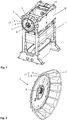
- FIG. 1 an embodiment of the drive unit according to the invention is shown. It shows a press frame 1 with the drive according to the invention 2.
- the drive unit 2 consists essentially of an electric motor 17, an output shaft 8 and a towing crank 5.
- the electric motor 17 consists of a stator 4 and a rotor 6, which are arranged concentrically to one another are.
- the stator 4 is rotatably connected via the stator housing 3 to the press head piece 16.
- the rotor 6 is rotatably mounted within the stator 4. The power transmission from the rotor 6 to the output shaft 8 via a towing crank. 5
- FIG. 2 a detail view of the press drive 2 is shown.
- Fig. 3 shows a sectional view through the drive unit 2 from Fig. 2 .
- the towing crank 5 consists of a connecting rod 9 and of the crankshaft 10.
- the connecting rod 9 is rotatably connected at one end via the connecting rod 11 with the rotor 6.
- the connecting rod 9 is rotatably connected to the crankshaft 10 via the bearing 12.
- the crankshaft 10 is non-rotatably mounted on the output shaft. 8
- the geometry of the towing crank is determined by the sizes A, B, C and D.
- the size A is the distance between the axes of rotation between the connecting rod bearing 11 and the bearing 12.
- the size B denotes the distance between the axes of rotation of the bearing 12 and the output shaft 8.
- the size C denotes the distance between the axes of rotation of the connecting rod bearing 11 and the rotor 6.
- the size D is a measure of the eccentricity of the towing crank and denotes the distance between the axes of rotation of the rotor 6 and the output shaft. 8 Due to the geometry of the towing crank 5, the course of the torque curve on the output shaft 8 is influenced. By changing the sizes A, B, C or D, the course of the torque curve can be influenced and optimized for the respective application while maintaining the same type of electric motor.
- the rotor is rotatably supported by the rotor bearing 7 in the stator housing 3 or in the press head piece 16.
- the rotor 6 and the stator 4 are constructed in the present example of rotor segments 14 and stator segments 15.
- the rotor 6 In operation, the rotor 6 is rotated by the electromagnetic forces between the stator 4 and the rotor 6.
- the rotor 6 transmits via the towing crank 5, ie via the connecting rod 9 and the crankshaft 10, a torque to the output shaft 8.
- the output shaft 8 itself is via an output shaft bearing 13 (see Fig. 1 ) stored in the press head piece 16.
- the power transmission from the output shaft 8 to the plunger in a conventional manner. So for example via an eccentric, which is arranged on the output shaft 8 and a connecting rod, which is mounted on the eccentric.
- the connecting rod then drives the plunger. But it is also conceivable that between the output shaft 8 and the plunger, a further transmission is arranged.
Landscapes
- Engineering & Computer Science (AREA)
- Mechanical Engineering (AREA)
- Power Engineering (AREA)
- Press Drives And Press Lines (AREA)
- Control Of Presses (AREA)
Claims (7)
- Unité d'entraînement pour une machine automatique de découpage ou une presse destinée à déplacer un poussoir ayant au moins un moteur électrique (17), qui présente un stator (4) et un rotor (6), qui sont disposés de manière concentrique l'un par rapport à l'autre, le stator (4) étant relié solidaire en rotation avec un châssis de presse et un arbre d'entraînement (8) destiné à déplacer le poussoir étant entraîné par le rotor (6), caractérisée en ce qu'entre le rotor (6) et l'arbre d'entraînement (8) est disposée une manivelle d'entraînement (5).
- Unité d'entraînement selon la revendication 1, caractérisée en ce que la manivelle d'entraînement (5) est reliée par une extrémité directement au rotor (6).
- Unité d'entraînement selon la revendication 2, caractérisée en ce que la manivelle d'entraînement (5) est disposée à l'intérieur du rotor (6).
- Unité d'entraînement selon l'une des revendications 1 à 3, caractérisée en ce que le rotor (6) est constitué de plusieurs segments (14) de rotor.
- Unité d'entraînement selon la revendication 4, caractérisée en ce que les segments (14) de rotor sont des aimants permanents.
- Unité d'entraînement selon l'une quelconque des revendications 1 à 5, caractérisée en ce que sur l'arbre d'entraînement (8) est disposé un excentrique, sur l'excentrique est montée une bielle qui sert à entraîner le poussoir.
- Unité d'entraînement selon l'une des revendications 1 à 6, caractérisée en ce que l'axe de l'arbre d'entraînement (8) est ménagé de manière excentrique par rapport à l'axe de rotor.
Priority Applications (1)
| Application Number | Priority Date | Filing Date | Title |
|---|---|---|---|
| SI201231475T SI2497632T1 (sl) | 2011-03-11 | 2012-03-02 | Pogonska enota za avtomatično štanco ali stiskalnico |
Applications Claiming Priority (1)
| Application Number | Priority Date | Filing Date | Title |
|---|---|---|---|
| ATA343/2011A AT511135B1 (de) | 2011-03-11 | 2011-03-11 | Antriebseinheit für einen stanzautomat oder eine presse |
Publications (3)
| Publication Number | Publication Date |
|---|---|
| EP2497632A2 EP2497632A2 (fr) | 2012-09-12 |
| EP2497632A3 EP2497632A3 (fr) | 2015-05-20 |
| EP2497632B1 true EP2497632B1 (fr) | 2018-09-19 |
Family
ID=45872770
Family Applications (1)
| Application Number | Title | Priority Date | Filing Date |
|---|---|---|---|
| EP12001444.4A Active EP2497632B1 (fr) | 2011-03-11 | 2012-03-02 | Unité d'entraînement pour une machine automatique de découpage ou une presse |
Country Status (4)
| Country | Link |
|---|---|
| EP (1) | EP2497632B1 (fr) |
| AT (1) | AT511135B1 (fr) |
| SI (1) | SI2497632T1 (fr) |
| TR (1) | TR201819103T4 (fr) |
Family Cites Families (4)
| Publication number | Priority date | Publication date | Assignee | Title |
|---|---|---|---|---|
| JP2006192494A (ja) * | 2005-01-17 | 2006-07-27 | Komatsu Ltd | プレス機械 |
| DE102008028652B3 (de) * | 2008-06-18 | 2010-01-14 | Schuler Pressen Gmbh & Co. Kg | Pressendirektantrieb |
| DE102009012111B4 (de) * | 2009-03-06 | 2014-10-02 | Andritz Technology And Asset Management Gmbh | Mechanische Umformpresse und Verfahren zur Betätigung dieser Umformpresse |
| DE102009029921B4 (de) | 2009-06-23 | 2012-06-06 | Schuler Pressen Gmbh & Co. Kg | Exzenterpressen-Direktantrieb |
-
2011
- 2011-03-11 AT ATA343/2011A patent/AT511135B1/de active
-
2012
- 2012-03-02 TR TR2018/19103T patent/TR201819103T4/tr unknown
- 2012-03-02 SI SI201231475T patent/SI2497632T1/sl unknown
- 2012-03-02 EP EP12001444.4A patent/EP2497632B1/fr active Active
Non-Patent Citations (1)
| Title |
|---|
| None * |
Also Published As
| Publication number | Publication date |
|---|---|
| AT511135B1 (de) | 2015-09-15 |
| SI2497632T1 (sl) | 2019-01-31 |
| TR201819103T4 (tr) | 2019-01-21 |
| AT511135A1 (de) | 2012-09-15 |
| EP2497632A3 (fr) | 2015-05-20 |
| EP2497632A2 (fr) | 2012-09-12 |
Similar Documents
| Publication | Publication Date | Title |
|---|---|---|
| DE102008028652B3 (de) | Pressendirektantrieb | |
| EP1748853B1 (fr) | Poinçonneuse equipee d'un mecanisme d'elevation/rotation motorise | |
| DE102009029921B4 (de) | Exzenterpressen-Direktantrieb | |
| DE10007505B4 (de) | Elektrische Antriebsvorrichtung | |
| DE102019112021A1 (de) | Hub-Dreh-Modul | |
| EP1627727B1 (fr) | Presse rotative pour comprimés | |
| EP2911871B1 (fr) | Dispositif d'entraînement | |
| DE19536727A1 (de) | Stanzenantrieb für eine Stanzpresse | |
| AT524824B1 (de) | Elektromechanischer Spindelantrieb | |
| EP2329944B1 (fr) | Presse destinée à produire une force de pression pour le traitement d'une pièce | |
| DE102011113624B4 (de) | Modulares Antriebssystem für eine Umformmaschine | |
| EP2008800A1 (fr) | Dispositif d'actionnement pour un automate de presse, de découpe ou de déformage | |
| EP2497632B1 (fr) | Unité d'entraînement pour une machine automatique de découpage ou une presse | |
| EP3697546B1 (fr) | Dispositif d'encochage et procédé d'entraînement d'un dispositif d'encochage | |
| DE102006042810A1 (de) | Hydrostatische Energieerzeugungseinheit | |
| WO2020043514A1 (fr) | Dispositif de mise en place d'un objet | |
| DE202013103426U1 (de) | Vorrichtung zur Erzeugung einer Bohrung in einem Werkstück oder eines Gewindes in einer Bohrung eines Werkstücks | |
| EP3260722B1 (fr) | Frein et système d'entraînement comprenant un frein | |
| EP2529922B1 (fr) | Dispositif d'actionnement pour un automate de presse, de découpe ou de déformage | |
| EP1529578B1 (fr) | Machine de travail, en particulier machine de cintrage de fil et/ou de bande | |
| DE202007009064U1 (de) | Antriebseinrichtung für einen Press-, Stanz- oder Umformautomaten | |
| EP2483065A1 (fr) | Procédé pour déplacer une unité de façonnage d'une machine | |
| DE4206329A1 (de) | Presseinrichtung fuer schneidemaschinen | |
| EP0886364B1 (fr) | Rotor pour une machine électrique | |
| DE202011101349U1 (de) | Antriebseinrichtung für einen Press-, Stanz- oder Umformautomaten |
Legal Events
| Date | Code | Title | Description |
|---|---|---|---|
| PUAI | Public reference made under article 153(3) epc to a published international application that has entered the european phase |
Free format text: ORIGINAL CODE: 0009012 |
|
| AK | Designated contracting states |
Kind code of ref document: A2 Designated state(s): AL AT BE BG CH CY CZ DE DK EE ES FI FR GB GR HR HU IE IS IT LI LT LU LV MC MK MT NL NO PL PT RO RS SE SI SK SM TR |
|
| AX | Request for extension of the european patent |
Extension state: BA ME |
|
| PUAL | Search report despatched |
Free format text: ORIGINAL CODE: 0009013 |
|
| AK | Designated contracting states |
Kind code of ref document: A3 Designated state(s): AL AT BE BG CH CY CZ DE DK EE ES FI FR GB GR HR HU IE IS IT LI LT LU LV MC MK MT NL NO PL PT RO RS SE SI SK SM TR |
|
| AX | Request for extension of the european patent |
Extension state: BA ME |
|
| RIC1 | Information provided on ipc code assigned before grant |
Ipc: B30B 1/26 20060101AFI20150416BHEP Ipc: H02K 7/14 20060101ALI20150416BHEP |
|
| 17P | Request for examination filed |
Effective date: 20151119 |
|
| RBV | Designated contracting states (corrected) |
Designated state(s): AL AT BE BG CH CY CZ DE DK EE ES FI FR GB GR HR HU IE IS IT LI LT LU LV MC MK MT NL NO PL PT RO RS SE SI SK SM TR |
|
| GRAP | Despatch of communication of intention to grant a patent |
Free format text: ORIGINAL CODE: EPIDOSNIGR1 |
|
| STAA | Information on the status of an ep patent application or granted ep patent |
Free format text: STATUS: GRANT OF PATENT IS INTENDED |
|
| INTG | Intention to grant announced |
Effective date: 20180621 |
|
| GRAS | Grant fee paid |
Free format text: ORIGINAL CODE: EPIDOSNIGR3 |
|
| GRAA | (expected) grant |
Free format text: ORIGINAL CODE: 0009210 |
|
| STAA | Information on the status of an ep patent application or granted ep patent |
Free format text: STATUS: THE PATENT HAS BEEN GRANTED |
|
| AK | Designated contracting states |
Kind code of ref document: B1 Designated state(s): AL AT BE BG CH CY CZ DE DK EE ES FI FR GB GR HR HU IE IS IT LI LT LU LV MC MK MT NL NO PL PT RO RS SE SI SK SM TR |
|
| REG | Reference to a national code |
Ref country code: GB Ref legal event code: FG4D Free format text: NOT ENGLISH |
|
| REG | Reference to a national code |
Ref country code: CH Ref legal event code: EP |
|
| REG | Reference to a national code |
Ref country code: AT Ref legal event code: REF Ref document number: 1042763 Country of ref document: AT Kind code of ref document: T Effective date: 20181015 |
|
| REG | Reference to a national code |
Ref country code: IE Ref legal event code: FG4D Free format text: LANGUAGE OF EP DOCUMENT: GERMAN |
|
| REG | Reference to a national code |
Ref country code: DE Ref legal event code: R096 Ref document number: 502012013452 Country of ref document: DE |
|
| REG | Reference to a national code |
Ref country code: NL Ref legal event code: MP Effective date: 20180919 |
|
| PG25 | Lapsed in a contracting state [announced via postgrant information from national office to epo] |
Ref country code: FI Free format text: LAPSE BECAUSE OF FAILURE TO SUBMIT A TRANSLATION OF THE DESCRIPTION OR TO PAY THE FEE WITHIN THE PRESCRIBED TIME-LIMIT Effective date: 20180919 Ref country code: GR Free format text: LAPSE BECAUSE OF FAILURE TO SUBMIT A TRANSLATION OF THE DESCRIPTION OR TO PAY THE FEE WITHIN THE PRESCRIBED TIME-LIMIT Effective date: 20181220 Ref country code: LT Free format text: LAPSE BECAUSE OF FAILURE TO SUBMIT A TRANSLATION OF THE DESCRIPTION OR TO PAY THE FEE WITHIN THE PRESCRIBED TIME-LIMIT Effective date: 20180919 Ref country code: RS Free format text: LAPSE BECAUSE OF FAILURE TO SUBMIT A TRANSLATION OF THE DESCRIPTION OR TO PAY THE FEE WITHIN THE PRESCRIBED TIME-LIMIT Effective date: 20180919 Ref country code: SE Free format text: LAPSE BECAUSE OF FAILURE TO SUBMIT A TRANSLATION OF THE DESCRIPTION OR TO PAY THE FEE WITHIN THE PRESCRIBED TIME-LIMIT Effective date: 20180919 Ref country code: NO Free format text: LAPSE BECAUSE OF FAILURE TO SUBMIT A TRANSLATION OF THE DESCRIPTION OR TO PAY THE FEE WITHIN THE PRESCRIBED TIME-LIMIT Effective date: 20181219 Ref country code: BG Free format text: LAPSE BECAUSE OF FAILURE TO SUBMIT A TRANSLATION OF THE DESCRIPTION OR TO PAY THE FEE WITHIN THE PRESCRIBED TIME-LIMIT Effective date: 20181219 |
|
| REG | Reference to a national code |
Ref country code: LT Ref legal event code: MG4D |
|
| PG25 | Lapsed in a contracting state [announced via postgrant information from national office to epo] |
Ref country code: LV Free format text: LAPSE BECAUSE OF FAILURE TO SUBMIT A TRANSLATION OF THE DESCRIPTION OR TO PAY THE FEE WITHIN THE PRESCRIBED TIME-LIMIT Effective date: 20180919 Ref country code: HR Free format text: LAPSE BECAUSE OF FAILURE TO SUBMIT A TRANSLATION OF THE DESCRIPTION OR TO PAY THE FEE WITHIN THE PRESCRIBED TIME-LIMIT Effective date: 20180919 Ref country code: AL Free format text: LAPSE BECAUSE OF FAILURE TO SUBMIT A TRANSLATION OF THE DESCRIPTION OR TO PAY THE FEE WITHIN THE PRESCRIBED TIME-LIMIT Effective date: 20180919 |
|
| PG25 | Lapsed in a contracting state [announced via postgrant information from national office to epo] |
Ref country code: ES Free format text: LAPSE BECAUSE OF FAILURE TO SUBMIT A TRANSLATION OF THE DESCRIPTION OR TO PAY THE FEE WITHIN THE PRESCRIBED TIME-LIMIT Effective date: 20180919 Ref country code: RO Free format text: LAPSE BECAUSE OF FAILURE TO SUBMIT A TRANSLATION OF THE DESCRIPTION OR TO PAY THE FEE WITHIN THE PRESCRIBED TIME-LIMIT Effective date: 20180919 Ref country code: NL Free format text: LAPSE BECAUSE OF FAILURE TO SUBMIT A TRANSLATION OF THE DESCRIPTION OR TO PAY THE FEE WITHIN THE PRESCRIBED TIME-LIMIT Effective date: 20180919 Ref country code: CZ Free format text: LAPSE BECAUSE OF FAILURE TO SUBMIT A TRANSLATION OF THE DESCRIPTION OR TO PAY THE FEE WITHIN THE PRESCRIBED TIME-LIMIT Effective date: 20180919 Ref country code: EE Free format text: LAPSE BECAUSE OF FAILURE TO SUBMIT A TRANSLATION OF THE DESCRIPTION OR TO PAY THE FEE WITHIN THE PRESCRIBED TIME-LIMIT Effective date: 20180919 Ref country code: PL Free format text: LAPSE BECAUSE OF FAILURE TO SUBMIT A TRANSLATION OF THE DESCRIPTION OR TO PAY THE FEE WITHIN THE PRESCRIBED TIME-LIMIT Effective date: 20180919 Ref country code: IS Free format text: LAPSE BECAUSE OF FAILURE TO SUBMIT A TRANSLATION OF THE DESCRIPTION OR TO PAY THE FEE WITHIN THE PRESCRIBED TIME-LIMIT Effective date: 20190119 |
|
| PG25 | Lapsed in a contracting state [announced via postgrant information from national office to epo] |
Ref country code: SK Free format text: LAPSE BECAUSE OF FAILURE TO SUBMIT A TRANSLATION OF THE DESCRIPTION OR TO PAY THE FEE WITHIN THE PRESCRIBED TIME-LIMIT Effective date: 20180919 Ref country code: PT Free format text: LAPSE BECAUSE OF FAILURE TO SUBMIT A TRANSLATION OF THE DESCRIPTION OR TO PAY THE FEE WITHIN THE PRESCRIBED TIME-LIMIT Effective date: 20190119 Ref country code: SM Free format text: LAPSE BECAUSE OF FAILURE TO SUBMIT A TRANSLATION OF THE DESCRIPTION OR TO PAY THE FEE WITHIN THE PRESCRIBED TIME-LIMIT Effective date: 20180919 |
|
| REG | Reference to a national code |
Ref country code: DE Ref legal event code: R097 Ref document number: 502012013452 Country of ref document: DE |
|
| PLBE | No opposition filed within time limit |
Free format text: ORIGINAL CODE: 0009261 |
|
| STAA | Information on the status of an ep patent application or granted ep patent |
Free format text: STATUS: NO OPPOSITION FILED WITHIN TIME LIMIT |
|
| PG25 | Lapsed in a contracting state [announced via postgrant information from national office to epo] |
Ref country code: DK Free format text: LAPSE BECAUSE OF FAILURE TO SUBMIT A TRANSLATION OF THE DESCRIPTION OR TO PAY THE FEE WITHIN THE PRESCRIBED TIME-LIMIT Effective date: 20180919 |
|
| 26N | No opposition filed |
Effective date: 20190620 |
|
| PG25 | Lapsed in a contracting state [announced via postgrant information from national office to epo] |
Ref country code: MC Free format text: LAPSE BECAUSE OF FAILURE TO SUBMIT A TRANSLATION OF THE DESCRIPTION OR TO PAY THE FEE WITHIN THE PRESCRIBED TIME-LIMIT Effective date: 20180919 |
|
| GBPC | Gb: european patent ceased through non-payment of renewal fee |
Effective date: 20190302 |
|
| PG25 | Lapsed in a contracting state [announced via postgrant information from national office to epo] |
Ref country code: LU Free format text: LAPSE BECAUSE OF NON-PAYMENT OF DUE FEES Effective date: 20190302 |
|
| REG | Reference to a national code |
Ref country code: BE Ref legal event code: MM Effective date: 20190331 |
|
| PG25 | Lapsed in a contracting state [announced via postgrant information from national office to epo] |
Ref country code: IE Free format text: LAPSE BECAUSE OF NON-PAYMENT OF DUE FEES Effective date: 20190302 Ref country code: GB Free format text: LAPSE BECAUSE OF NON-PAYMENT OF DUE FEES Effective date: 20190302 |
|
| PG25 | Lapsed in a contracting state [announced via postgrant information from national office to epo] |
Ref country code: FR Free format text: LAPSE BECAUSE OF NON-PAYMENT OF DUE FEES Effective date: 20190331 Ref country code: BE Free format text: LAPSE BECAUSE OF NON-PAYMENT OF DUE FEES Effective date: 20190331 |
|
| PG25 | Lapsed in a contracting state [announced via postgrant information from national office to epo] |
Ref country code: MT Free format text: LAPSE BECAUSE OF FAILURE TO SUBMIT A TRANSLATION OF THE DESCRIPTION OR TO PAY THE FEE WITHIN THE PRESCRIBED TIME-LIMIT Effective date: 20180919 |
|
| REG | Reference to a national code |
Ref country code: AT Ref legal event code: MM01 Ref document number: 1042763 Country of ref document: AT Kind code of ref document: T Effective date: 20190302 |
|
| PG25 | Lapsed in a contracting state [announced via postgrant information from national office to epo] |
Ref country code: AT Free format text: LAPSE BECAUSE OF NON-PAYMENT OF DUE FEES Effective date: 20190302 |
|
| PG25 | Lapsed in a contracting state [announced via postgrant information from national office to epo] |
Ref country code: CY Free format text: LAPSE BECAUSE OF FAILURE TO SUBMIT A TRANSLATION OF THE DESCRIPTION OR TO PAY THE FEE WITHIN THE PRESCRIBED TIME-LIMIT Effective date: 20180919 |
|
| PG25 | Lapsed in a contracting state [announced via postgrant information from national office to epo] |
Ref country code: HU Free format text: LAPSE BECAUSE OF FAILURE TO SUBMIT A TRANSLATION OF THE DESCRIPTION OR TO PAY THE FEE WITHIN THE PRESCRIBED TIME-LIMIT; INVALID AB INITIO Effective date: 20120302 |
|
| PG25 | Lapsed in a contracting state [announced via postgrant information from national office to epo] |
Ref country code: MK Free format text: LAPSE BECAUSE OF FAILURE TO SUBMIT A TRANSLATION OF THE DESCRIPTION OR TO PAY THE FEE WITHIN THE PRESCRIBED TIME-LIMIT Effective date: 20180919 |
|
| PGFP | Annual fee paid to national office [announced via postgrant information from national office to epo] |
Ref country code: TR Payment date: 20240223 Year of fee payment: 13 |
|
| PGFP | Annual fee paid to national office [announced via postgrant information from national office to epo] |
Ref country code: SI Payment date: 20250220 Year of fee payment: 14 |
|
| PGFP | Annual fee paid to national office [announced via postgrant information from national office to epo] |
Ref country code: CH Payment date: 20250401 Year of fee payment: 14 |
|
| REG | Reference to a national code |
Ref country code: CH Ref legal event code: U11 Free format text: ST27 STATUS EVENT CODE: U-0-0-U10-U11 (AS PROVIDED BY THE NATIONAL OFFICE) Effective date: 20260401 |
|
| PGFP | Annual fee paid to national office [announced via postgrant information from national office to epo] |
Ref country code: DE Payment date: 20260319 Year of fee payment: 15 |
|
| PGFP | Annual fee paid to national office [announced via postgrant information from national office to epo] |
Ref country code: IT Payment date: 20260324 Year of fee payment: 15 |