EP2497883A2 - Dispositif d'arrêt d'extraction - Google Patents
Dispositif d'arrêt d'extraction Download PDFInfo
- Publication number
- EP2497883A2 EP2497883A2 EP12001462A EP12001462A EP2497883A2 EP 2497883 A2 EP2497883 A2 EP 2497883A2 EP 12001462 A EP12001462 A EP 12001462A EP 12001462 A EP12001462 A EP 12001462A EP 2497883 A2 EP2497883 A2 EP 2497883A2
- Authority
- EP
- European Patent Office
- Prior art keywords
- support
- support surface
- pull
- guide
- elements
- Prior art date
- Legal status (The legal status is an assumption and is not a legal conclusion. Google has not performed a legal analysis and makes no representation as to the accuracy of the status listed.)
- Granted
Links
Images


Classifications
-
- E—FIXED CONSTRUCTIONS
- E05—LOCKS; KEYS; WINDOW OR DOOR FITTINGS; SAFES
- E05B—LOCKS; ACCESSORIES THEREFOR; HANDCUFFS
- E05B65/00—Locks or fastenings for special use
- E05B65/46—Locks or fastenings for special use for drawers
-
- A—HUMAN NECESSITIES
- A47—FURNITURE; DOMESTIC ARTICLES OR APPLIANCES; COFFEE MILLS; SPICE MILLS; SUCTION CLEANERS IN GENERAL
- A47B—TABLES; DESKS; OFFICE FURNITURE; CABINETS; DRAWERS; GENERAL DETAILS OF FURNITURE
- A47B88/00—Drawers for tables, cabinets or like furniture; Guides for drawers
- A47B88/40—Sliding drawers; Slides or guides therefor
- A47B88/473—Braking devices, e.g. linear or rotational dampers or friction brakes; Buffers; End stops
- A47B88/477—Buffers; End stops
-
- E—FIXED CONSTRUCTIONS
- E05—LOCKS; KEYS; WINDOW OR DOOR FITTINGS; SAFES
- E05B—LOCKS; ACCESSORIES THEREFOR; HANDCUFFS
- E05B65/00—Locks or fastenings for special use
- E05B65/46—Locks or fastenings for special use for drawers
- E05B65/462—Locks or fastenings for special use for drawers for two or more drawers
- E05B65/463—Drawer interlock or anti-tilt mechanisms, i.e. when one drawer is open, at least one of the remaining drawers is locked
- E05B65/464—Drawer interlock or anti-tilt mechanisms, i.e. when one drawer is open, at least one of the remaining drawers is locked comprising two or more lock elements aligned in end-to-end abutting relation
Definitions
- the present invention relates to a pull-out locking device for at least two furniture parts which can be pushed into and out of the furniture body, in particular drawers, wherein the pull-out locking device has at least one guide rail and a sequence of support elements displaceably mounted on an elongated guide element of the guide rail in its longitudinal direction, wherein each support element, seen in an operating position of the pull-out device, an upper support surface for abutment with a support member disposed adjacent thereto and a lower support surface for abutment with a support member arranged below below and at least one further support surface for abutment on above or below adjacent support element wherein each support element has a release position for abutment with its upper support surface on the adjacently disposed above support element and for contact with its lower support surface on the adjacently disposed below support member and wherein each support member has a locking position for engagement with its other support surface on above or below adjacent support member.
- Pull-out devices are known in a variety of forms in the art. They serve to prevent additional pull-out furniture parts such as drawers can be pulled out of a furniture body, if already other correspondingly extendable furniture parts or drawers are pulled out of this furniture body. The aim is to prevent the furniture body from being accidentally out of balance or falling over when too many pull-out furniture parts or drawers have been pulled out of it.
- Ausziehsperrvoriquesen already block the withdrawal of other extendable furniture parts, if only a single extendable Furniture part is pulled out of the furniture body.
- Such Ausziehsperrvorettien are eg from the DE 195 47 049 A1 known. There, the support elements are constructed in several parts.
- the support elements on rods which are slidably mounted in the guide element of the guide rail.
- the other tiltable lever On the rod-like parts of the support elements shown there are arranged on the other tiltable lever. These are also assigned to the support element.
- the lower support surface is located on an additional roller, which is arranged on the rod-shaped part of the support element and thus is also assigned to the respective support element.
- the upper support surface and the other support surface are located on the pivoting lever.
- each support element has a so-called monobloc element, which has the upper and the lower support surface.
- each support element additionally but also one, opposite the monobloc element pivotable hook, on which there is the further support surface for the blocking position.
- the object of the invention is to improve generic Ausziehsperrvortechnischen in the sense of the simplest possible structure.
- each support element as one, the upper support surface and the lower support surface and the further support surface in rigidly interconnecting body and that each support member is pivotally mounted about a pivot axis between the locking position and the release position on the guide member and all Support surfaces are arranged outside the guide element.
- a basic idea of the invention is thus to use, instead of the previous multi-part construction, supporting elements which, as a rigid body, have at least both the upper support surface and the lower support surface and also the further support surface. These three support surfaces are thus formed rigidly in the form of a body, said body so that the respective support member is pivotally mounted about a pivot axis between the locking position and the release position on the guide member.
- the support elements can also be referred to as pawls or blocking body accordingly.
- the support elements forming body can also have more than just support surfaces. The fact that all support surfaces are arranged outside the guide element, makes it possible to provide a relatively large stroke between locking position and release position by correspondingly large training of the support surfaces and correspondingly large distances between the support surfaces.
- the guide rail is that component which as such is usually fastened directly in the furniture carcass, and insofar carries the remaining parts of the pull-out device. It includes or contributes in addition to the guide element, for example, also upper and lower stops, as they are mentioned below.
- the guide rail usually in addition to the guide element and mounting tabs with which the guide rail can be attached to the furniture body.
- a lock may be provided for blocking the entire Ausziehsperrvorraum.
- the guide element is only the part of the guide rail on or in which the support elements are actually slidably mounted.
- the guide element can be designed, for example, as a corresponding undercut groove, that is to say channel-like.
- each support element has a, preferably T-shaped, guide pin for slidable mounting on, preferably by means of engagement in the guide element of the guide rail.
- the guide pin is conveniently also a part of the inherently rigid Body, which forms the respective support element.
- the support elements according to the invention can have, for example, corresponding guide rings or the like, which surround the guide element annularly.
- the guide element is advantageously in the operating position of the pull-out device in the vertical direction extends longitudinally. His longitudinal direction thus runs conveniently parallel to the vertical.
- the pivot axes about which the respective support elements are pivotable, preferably extend orthogonal to the longitudinal direction of the guide element.
- the guide element in the operating position of the pull-out device in the horizontal direction extends longitudinally or extends its longitudinal extent in said operating position at an angle between the vertical and the horizontal.
- each support element is designed as a, the lower support surface and the upper support surface and the other support surface, and preferably also the guide pin, in integrally interconnecting body.
- the support elements may also be designed as a rigid body, if individual parts of the support element consist of mutually different materials or parts, but these parts are just fixed and rigidly interconnected.
- each support element is designed as a one-piece, preferably injection-molded, plastic body or as a one-piece metal or ceramic body.
- the pull-out locking device has release elements with which the support elements can be actuated or pivoted.
- at least one such triggering element is provided per extendable furniture part.
- Preferred embodiments of the interaction between the support element and the triggering element provide that each support element has a pivot arm arranged eccentrically with respect to its pivot axis for pivoting the support element about its pivot axis by means of a pivotable on the extendable furniture part, preferably peg-shaped, triggering element.
- triggering elements do not necessarily have to be pin-shaped, but may also have other shapes.
- these triggering elements at least cooperate with the eccentrically arranged pivot arms to pivot the respective support element between the release position and the blocking position and / or forth.
- the pivot arms may have recesses for receiving a particular peg-shaped release element for this purpose. But it is just as possible, to name just another example, that a peg-shaped extension is arranged on the pivot arm, which cooperates with a corresponding recess in the trigger element.
- Preferred embodiments of a Ausziehsperrvoroplasty invention further provide that, preferably exactly, an a Popeen furniture part can be moved, preferably pin-shaped, trigger element between two adjacently arranged support elements, whereby the trigger element forcing one of the support elements forcibly from its release position into its blocking position or vice versa swings.
- an a Popeen furniture part can be moved, preferably pin-shaped, trigger element between two adjacently arranged support elements, whereby the trigger element forcing one of the support elements forcibly from its release position into its blocking position or vice versa swings.
- the upper support surface and the lower support surface in each case have a run-on slope for a, preferably pin-shaped, release element arranged on the extendable furniture part.
- the displaceability of the support elements along the guide element between two stops is limited, with all remaining or other support elements are fixed in position relative to the attacks when or after at least one of the support elements has been arranged in its blocking position , This is especially true when all other extendable furniture parts or drawers should already be blocked when a single pull-out furniture part or a single drawer has moved out of the furniture body. If you want to allow the withdrawal of more than one pull-out furniture part of the furniture body, the fixation of the remaining support elements between the stops only when a corresponding number of support elements are arranged in their locked position. This can be easily established by appropriate arrangements of the attacks in coordination with the dimensioning of the support elements.
- all supporting elements of the pull-out device have an identical shape.
- the support elements should give a certain grid.
- the corresponding extension of the associated drawers or extendable furniture parts in the longitudinal direction of the guide element should then be an integer multiple of the mentioned longitudinal extension of a support element arranged in its release position.
- Preferred embodiments provide true integer multiples, ie integral multiples greater than or equal to 2.
- the said integer multiple can also be 1.
- a first group of Ausziehsperrvoriquesen provides that only guide elements according to the invention, preferably with mutually identical shape, are arranged on the guide element.
- other embodiments of the invention provide that between the support elements according to the invention intermediate elements are arranged, which also along the guide element are displaceable. This is particularly useful if the dimensioning of the support elements, a relatively fine grid is given, but in some areas relatively large drawers are available.
- some support elements can then be replaced by appropriate intermediate elements. These intermediate elements can then be simpler in their construction. For example, they do not have to be mounted pivotably on the guide element like the support elements about a pivot axis.
- the intermediate element may be at the intermediate elements to simple rod-like structures or the like.
- the intermediate element should fit in the predetermined by the dimensioning of the support elements grid.
- preferred embodiments provide that between at least two support elements at least one guide element in the longitudinal direction slidably mounted intermediate member is arranged, wherein the longitudinal extension of the intermediate element, seen in the longitudinal direction of the guide element, a, preferably true, integer multiple of the longitudinal extent of one in his Release position arranged support element is.
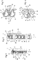
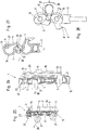
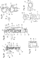
- FIG. 1 to 16 For the first embodiment in the Fig. 1 to 16 four different operating states are shown. There are four figures for each operating state. In the Fig. 1 to 4 an operating state is shown in which the not shown here extendable furniture parts or drawers are completely inserted into the furniture body, also not shown. There are thus all support elements 5 still in their release position in which one of the furniture parts, not shown here, can be pulled out of the furniture body.
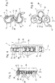
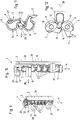
- the Fig. 5 to 8 and the Fig. 9 to 12 show two operating states occurring immediately after each other, when in the course of pulling out one of the movable furniture parts, here the upper, has been pivoted from the furniture body of one of the support elements 5 already in its locked position.
- the Fig. 5 to 8 and the Fig. 9 to 12 show two operating states occurring immediately after each other, when in the course of pulling out one of the movable furniture parts, here the upper, has been pivoted from the furniture body of one of the support elements 5 already in its locked position.
- the Fig. 1 to 4 an operating state is
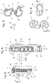
- FIG. 13 to 16 then still show the situation in which the trigger element 12 is completely pulled out of the array of support members 5 and in the blocking position located support member 5 prevents the withdrawal of the second furniture part.
- the direction in which the furniture parts, not shown, are pulled out of the furniture body is indicated by the arrow 28.
- the re-insertion of the furniture parts or drawers in the furniture carcass takes place in the opposite direction.
- the illustrated embodiment of a pull-out device 1 is equipped with two trigger element carriers 21 and corresponding trigger elements 12 in the variant shown. In the illustrated variant, the pull-out device thus serves for two pull-out furniture parts or drawers.
- the drawer heights must ultimately only fit the grid dimension of the support elements 5.
- the grid dimension is predetermined by the longitudinal extent 19 of the support elements 5 in their release position, in which, in the example shown, the lower support surface 7 of the respective upper support element 5 is arranged on the upper support surface 6 of the respective lower adjacent support element 5.
- the Fig. 1 . 5 . 9 and 13 each show a perspective view of the inventively designed Ausziehsperrvorraum 1.
- Die Fig. 2 . 6 . 10 and 14 each show a side view.
- Fig. 3 . 7 . 11 and 15 each of the two cooperating with the upper trigger element 12 supporting elements 5 are drawn out.
- the Fig. 4 . 8th . 12 and 16 With reference to FIGS Fig. 3 . 7 . 11 and 15 in each case the views from the opposite side, ie from the direction of the guide element. 3
- the illustrated pull-out locking device 1 has a guide rail 2. This in turn has a mounting plate 24, with which the Ausziehsperrvorraum 1 is attached to the furniture body, not shown here. Furthermore, the guide rail 2, the guide element 3, on which the support elements 5 are slidably mounted in the longitudinal direction 4 of the guide element 3. In the exemplary embodiment shown, the longitudinal direction 4 of the guide element 3 runs parallel to the vertical.
- the guide element 3 is executed in the embodiment shown as a groove-shaped channel with marginal undercuts.
- Each support element has a guide pin 10, with which the respective support element 5 is displaceably mounted in the guide element 3 or engages in the guide element 3.
- Fig. 33 shows a side view of the support member 5 in the well to recognize that the guide pin 10 of this embodiment is each T-head-shaped.
- the guided directly in the guide member 3 head plate 29 of the guide pin 10 is formed in the embodiment shown so that it limits the pivot angle of the respective support member 5 about its respective pivot axis 9 by corresponding stop in the groove-shaped guide member 3. But this does not necessarily have to be the case.
- the support elements 5 used in the first embodiment are all formed identically. In the exemplary embodiment shown, it is an integral body whose parts are rigidly interconnected. In this respect, you can also call the support elements 5 as integral pawls.
- the support elements 5 are displaceable along the guide element 3 or its longitudinal direction 4, wherein the displaceability is, however, limited by the upper stop 16 and the lower stop 15. It would in principle be conceivable to permanently fix the distance between the upper and lower stops 16 and 15 to a level which corresponds to the longitudinal extension 20 of one of the support elements 5 in the locked position plus the sum of the longitudinal extensions 19 of the remaining support elements 5 in the release position equivalent.
- the lower stop 15 is fixedly secured to the guide rail 2, while the upper stop 16 itself can be pushed up against a spring, not shown here, a piece far up until it abuts a not shown above lying further stop and thereby one, in This position no longer displaceable stop for the top support member 5 forms.
- This somewhat more complex variant of the design of the upper stop 16 was chosen here in order to make the shown pull-out locking device 1 lockable.
- the lock 22 is provided with its rotary latch 23. In the locking position of the lock 22 prevents the trained as an eccentric rotary latch 23 that the stop 16 of the in Fig. 2 shown position can be moved upwards.
- the rotary latch 23 is rotated by appropriate actuation of the lock 22 in such a way that it releases the upper stop 16, then this can be pushed up a little when one of the support elements 5 is pivoted out of the release position into the blocking position.
- the upper stop 16 then reaches its end or stop position when said support element 5 is fully pivoted into its blocking position. Then it is in the first embodiment shown no longer possible to pivot more support elements 5 from its release position to its blocking position, which prevents more than one drawer or more than one extendable furniture part can be pulled out of the body.
- the distance between the stops 15 and 16 must be matched to the size of the support elements 5 that only the desired maximum number of support elements 5 can be brought into the blocking position before the remaining support elements are blocked in their release position unverschwenkbar and not in the blocking position can be pivoted.
- the triggering element 12 which is connected via the trigger element carrier 21 to the extendable furniture part, not shown here, is designed as a journal in the embodiment shown and is located in the Fig. 1 to 4 in Ausziehraum 28 seen behind the two in the 3 and 4 drawn support elements 5. More precisely, the trigger element 12 is arranged in this position in a receiving recess 25 of the eccentric with respect to the pivot axis 9 on the support member 5 integrally formed pivot arm 11.
- the upper support member 5 is supported with its lower support surface 7 in this release position on the upper support surface 6 of the underlying support element 5 from.
- the further support surface 8, which is located in the embodiment shown at the end remote from the respective pivot axis 9 end of the pivot arm 11 is not active in the release position.
- each support element has exactly three support surfaces, namely an upper support surface 6, a lower support surface 7 and a further support surface 8. In the embodiment shown, this is realized consuming.
- the one of the two further support surfaces 8 is supported in the blocking position shown in the following figures on an additional support surface 27 of the other support member 5, while the second further support surface 8 'on the upper support surface 6 of the underlying Supporting element 5 is supported.
- this is of course only an example, which should show that not only exactly three but also more than three support surfaces per support element 5 are possible according to the invention.
- the trigger element 12 is movably mounted relative to the trigger element carrier 21 and thus to the extendable furniture part, not shown here. In the embodiment shown, this is realized by the guide pin 12 is pivotally mounted in the trigger element carrier 21. Other embodiments would be a displaceable mounting of the trigger element 12 in a corresponding guide groove or the like.
- the variants with a movable triggering element 12 can be used in order to enable as low a movement as possible movement of the overall system of the pull-out device 1. In simple variants, however, the corresponding triggering elements 12 can also be fastened fixedly to the triggering element carrier 21 or to the extendable furniture part.
- the Fig. 1 to 4 show, as I said, the position in which the two furniture parts not shown here are completely inserted into the furniture body, not shown here. In this situation, all support elements 5 are in their release position.
- the 3 and 4 show the position of the trigger element 12 in the withdrawal direction 28 behind the superimposed upper and lower support surfaces 6 and 7 of the superposed support elements 5. Now one of the two movable furniture parts, here the upper, pulled out in the direction 28 from the furniture body, so meets the trigger element By further pulling out the movable furniture part and thus the trigger element 12 in the direction 28, one of the support elements 5, here the top, from its release position about the pivot axis 9 in the, in the Fig. 5 to 8 illustrated blocking position pivoted. In the locked position, in particular according to the FIGS.
- the lower drawer, not shown here, together with the lower trigger element carrier 21 can be moved out of the fully inserted position.
- the trigger element 12 to be able to pull out of the receiving recess 25 of the support member 5 is pivoted at a further train on the movable furniture part in the withdrawal 28, the trigger element 12 in the trigger element carrier 21, whereby it is possible, the trigger element 12 on the drive lug 26 over in the pull-28th to move on.
- This situation is in the Fig. 9 to 12 shown.
- the trigger element 12 leaves the receiving recess 25 completely.
- the pull-out furniture part is then as far as desired, so pulled out a maximum to its open end position. Meanwhile, brought into the blocking position support member 5 blocks the displacement of the remaining support elements 5 in the longitudinal direction 4 of the guide element 3 between the stops 15 and 16 so that no further drawer can be pulled out in the pull-out 28 of the pull-out device 1. This is only possible again when the displaceable previously moved furniture part in the insertion direction, ie opposite direction 28 has been pushed back so far that the trigger element 12 by corresponding stop on the pivot arm 11, the support member 5 again in its release position according to Fig. 1 to 4 has panned.
- FIGS. 17 to 32 a second embodiment according to the invention is shown, in which not only support elements 5 are arranged exclusively on the guide element 3.
- a part of the support elements 5 is replaced by an intermediate element 17.
- the intermediate element 17 is displaceable in the longitudinal direction 4 on the guide element 3, but unlike the support elements 5 is not pivotable.
- Corresponding intermediate elements 17 can be used as a substitute for supporting elements 5 wherever no triggering elements 12 are extended and retracted. It is thus possible to bridge with the intermediate elements 17 corresponding spaces between extendable furniture parts or drawers.
- the intermediate element 17 has a support surface, which cooperates with the lower support surface 7 of the overlying support element 5 and corresponds in shape with this.
- the intermediate element 17 has a corresponding lower support surface, which cooperates with the upper support surface 6 of the underlying support element 5 and is formed correspondingly corresponding.
- the longitudinal extension 18 of the intermediate element 17 should fit into the predetermined by the support elements 5 pitch. It is preferably provided that the longitudinal extension 18 of the intermediate element 17 in the longitudinal direction 4 corresponds to the longitudinal extension 19 of a support element 5 in the same direction, or a true integer multiple, that is an integer multiple greater than or equal to 2.
Landscapes
- Drawers Of Furniture (AREA)
- Specific Sealing Or Ventilating Devices For Doors And Windows (AREA)
- Electrical Discharge Machining, Electrochemical Machining, And Combined Machining (AREA)
- Surgical Instruments (AREA)
Priority Applications (2)
| Application Number | Priority Date | Filing Date | Title |
|---|---|---|---|
| SI201231466T SI2497883T1 (sl) | 2011-03-10 | 2012-03-05 | Blokirna naprava izvleka |
| PL12001462T PL2497883T3 (pl) | 2011-03-10 | 2012-03-05 | Urządzenie blokujące wysuwanie |
Applications Claiming Priority (1)
| Application Number | Priority Date | Filing Date | Title |
|---|---|---|---|
| ATA324/2011A AT511116B1 (de) | 2011-03-10 | 2011-03-10 | Ausziehsperrvorrichtung |
Publications (3)
| Publication Number | Publication Date |
|---|---|
| EP2497883A2 true EP2497883A2 (fr) | 2012-09-12 |
| EP2497883A3 EP2497883A3 (fr) | 2017-02-15 |
| EP2497883B1 EP2497883B1 (fr) | 2018-08-22 |
Family
ID=45877945
Family Applications (1)
| Application Number | Title | Priority Date | Filing Date |
|---|---|---|---|
| EP12001462.6A Active EP2497883B1 (fr) | 2011-03-10 | 2012-03-05 | Dispositif d'arrêt d'extraction |
Country Status (8)
| Country | Link |
|---|---|
| US (2) | US8899699B2 (fr) |
| EP (1) | EP2497883B1 (fr) |
| AT (1) | AT511116B1 (fr) |
| DK (1) | DK2497883T3 (fr) |
| ES (1) | ES2694565T3 (fr) |
| PL (1) | PL2497883T3 (fr) |
| SI (1) | SI2497883T1 (fr) |
| TR (1) | TR201815843T4 (fr) |
Cited By (1)
| Publication number | Priority date | Publication date | Assignee | Title |
|---|---|---|---|---|
| EP2778325A2 (fr) | 2013-03-14 | 2014-09-17 | FULTERER Gesellschaft mbH | Dispositif de verrouillage |
Families Citing this family (8)
| Publication number | Priority date | Publication date | Assignee | Title |
|---|---|---|---|---|
| ITMO20130150A1 (it) * | 2013-05-28 | 2014-11-29 | Fami Srl | ¿dispositivo di chiusura antiribaltamento per armadi a cassetti¿ |
| ITMO20130151A1 (it) | 2013-05-28 | 2014-11-29 | Fami Srl | Sistema di chiusura per armadi a cassetti |
| AT516236B1 (de) | 2014-08-25 | 2016-11-15 | Fulterer Gmbh | Ausziehsperre |
| CN106907066B (zh) * | 2017-03-28 | 2018-09-11 | 江苏通润装备科技股份有限公司 | 一种相互制约式抽屉锁紧机构 |
| US10869550B2 (en) | 2019-05-10 | 2020-12-22 | AMQ Solutions, LLC | Mobile office storage assembly |
| DE102019006380A1 (de) * | 2019-09-10 | 2021-03-11 | SW-Stahl GmbH | Aufbewahrungseinheit für Werkzeuge |
| DE102020127403A1 (de) * | 2020-10-17 | 2022-04-21 | Paul Hettich Gmbh & Co. Kg | Sperrvorrichtung für bewegbare Möbelteile |
| CA3210448A1 (en) * | 2023-08-28 | 2025-06-18 | Wesko Locks Ltd. | Tamper resistant anti-tip system |
Citations (2)
| Publication number | Priority date | Publication date | Assignee | Title |
|---|---|---|---|---|
| DE19547049A1 (de) | 1994-12-20 | 1996-06-27 | Huwil Werke Gmbh | Auszugsperre für übereinander angeordnete Schubladen |
| EP2128364A1 (fr) | 2007-02-23 | 2009-12-02 | Ojmar S.A. | Système de blocage pour tiroirs de meubles |
Family Cites Families (33)
| Publication number | Priority date | Publication date | Assignee | Title |
|---|---|---|---|---|
| US4298236A (en) * | 1980-07-14 | 1981-11-03 | Artopex Inc. | Safety lock system for vertically stacked storage elements |
| DE3431386A1 (de) * | 1984-08-25 | 1986-03-06 | Fa. Anton Kessel, 7945 Andelfingen | Schubladenschrank mit auszugssperre |
| US4711505A (en) * | 1987-02-06 | 1987-12-08 | Lakso Matthew L | Locking system |
| DE3822678A1 (de) | 1988-07-05 | 1990-01-11 | Hettich Paul Gmbh & Co | Beschlag fuer ein mehrere uebereinander angeordnete schubkaesten aufweisendes moebel |
| US5074627A (en) * | 1990-07-13 | 1991-12-24 | Reff Incorporated | Anti-tilt and locking mechanism for multi-drawer cabinets |
| FR2699057B1 (fr) * | 1992-12-11 | 1995-01-13 | Ronis Sa | Dispositif réglable de condamnation des tiroirs d'un meuble et meuble équipé d'un tel dispositif. |
| US5427445A (en) * | 1994-10-05 | 1995-06-27 | Quest Engineering | Drawer interlock structure |
| EP0738813A1 (fr) | 1995-03-24 | 1996-10-23 | Merz-Meyer Ag | Meuble |
| GB2302906B (en) * | 1995-06-30 | 1999-07-07 | Maine Engineering Limited | Interlock meachanism for slidable units |
| DE19527898C1 (de) | 1995-07-29 | 1996-08-29 | Mauro Romagnoni | Schubladen-Verriegelungssystem |
| DE19527848C1 (de) | 1995-07-29 | 1997-02-20 | Mauro Romagnoni | Schubladen-Verriegelungssystem |
| US5599078A (en) | 1995-11-08 | 1997-02-04 | Alb Industries Ltd. | Anti-tip device for file cabinets |
| EP0818597B1 (fr) | 1996-07-12 | 2002-10-02 | ACCURIDE INTERNATIONAL, Inc. | Système de verrouillage avec fermeture à barre pour tiroirs |
| GB2318042A (en) | 1996-10-12 | 1998-04-15 | Andrew Clive Jackson | Drawer interlock for a cabinet |
| DE29620152U1 (de) | 1996-11-20 | 1997-04-03 | Hekna Hermann Knapp GmbH & Co. KG, 42551 Velbert | Zentralverriegelung für Möbel |
| US6254205B1 (en) | 1999-02-02 | 2001-07-03 | Thomas Regout Usa Inc. | Rail assembly with homing device and interlock |
| ES2188297B1 (es) | 1999-06-10 | 2004-05-01 | Ojmar, S.A. | Sistema de bloqueo para cajones de muebles. |
| DE20007034U1 (de) | 2000-04-17 | 2000-08-03 | Huwil-Werke GmbH Möbelschloß- und Beschlagfabriken, 53809 Ruppichteroth | Ausziehsperre für mehrere übereinander angeordnete Schubladen |
| DE20008266U1 (de) | 2000-05-08 | 2000-08-03 | Huwil-Werke GmbH Möbelschloß- und Beschlagfabriken, 53809 Ruppichteroth | Ausziehsperre für und Möbel mit einer solchen übereinander angeordnete Schubladen |
| TW439838U (en) * | 2000-10-26 | 2001-06-07 | Nan Juen Int Co Ltd | Driving and mutual-locking device among drawers |
| US6634726B1 (en) | 2001-05-30 | 2003-10-21 | Snap-On Technologies, Inc. | Multiple drawer cabinet allowing one drawer opened at a time |
| US6568771B2 (en) | 2001-06-01 | 2003-05-27 | Tk Canada Limited | Drawer interlock |
| US6722749B1 (en) | 2001-08-14 | 2004-04-20 | Snap-On Technologies, Inc. | Drawer open position controller |
| DE10206854C1 (de) | 2002-02-18 | 2003-08-21 | Huwil Werke Gmbh | Ausziehsperre für übereinander angeordnete Schubladen |
| AT7040U1 (de) | 2003-02-21 | 2004-09-27 | Fulterer Gmbh | Ausziehsperreinrichtung |
| WO2004104336A1 (fr) | 2003-05-23 | 2004-12-02 | Ojmar, S.A. | Systeme de blocage pour tiroirs de meubles |
| AT413630B (de) | 2003-07-24 | 2006-04-15 | Fulterer Gmbh | Ausziehsperreinrichtung |
| US20050040659A1 (en) | 2003-08-20 | 2005-02-24 | Titus International Plc | Furniture |
| TWM299510U (en) | 2006-02-08 | 2006-10-21 | Nan Juen Int Co Ltd | Linkage mutual-locking mechanism for slide rail of drawer |
| ES2304214B1 (es) | 2007-03-07 | 2009-08-03 | Ojmar, S.A. | Sistema de extraccion selectiva de cajones. |
| EP2053187A1 (fr) * | 2007-10-24 | 2009-04-29 | O.M.R. di Roberto Olivi & C. S.n.c. | Mécanisme anti-basculement pour meubles à tiroirs |
| AT508905B1 (de) | 2009-12-07 | 2011-05-15 | Fulterer Gmbh | Ausziehsperrvorrichtung |
| AT509331B1 (de) | 2010-05-28 | 2011-08-15 | Fulterer Gmbh | Ausziehsperrvorrichtung für mindestens zwei ausziehbare möbelteile |
-
2011
- 2011-03-10 AT ATA324/2011A patent/AT511116B1/de not_active IP Right Cessation
-
2012
- 2012-03-05 ES ES12001462.6T patent/ES2694565T3/es active Active
- 2012-03-05 SI SI201231466T patent/SI2497883T1/sl unknown
- 2012-03-05 EP EP12001462.6A patent/EP2497883B1/fr active Active
- 2012-03-05 PL PL12001462T patent/PL2497883T3/pl unknown
- 2012-03-05 TR TR2018/15843T patent/TR201815843T4/tr unknown
- 2012-03-05 DK DK12001462.6T patent/DK2497883T3/en active
- 2012-03-12 US US13/417,596 patent/US8899699B2/en active Active
-
2014
- 2014-08-22 US US14/466,344 patent/US8936326B2/en active Active
Patent Citations (2)
| Publication number | Priority date | Publication date | Assignee | Title |
|---|---|---|---|---|
| DE19547049A1 (de) | 1994-12-20 | 1996-06-27 | Huwil Werke Gmbh | Auszugsperre für übereinander angeordnete Schubladen |
| EP2128364A1 (fr) | 2007-02-23 | 2009-12-02 | Ojmar S.A. | Système de blocage pour tiroirs de meubles |
Cited By (2)
| Publication number | Priority date | Publication date | Assignee | Title |
|---|---|---|---|---|
| EP2778325A2 (fr) | 2013-03-14 | 2014-09-17 | FULTERER Gesellschaft mbH | Dispositif de verrouillage |
| EP2778325A3 (fr) * | 2013-03-14 | 2015-06-17 | FULTERER Gesellschaft mbH | Dispositif de verrouillage |
Also Published As
| Publication number | Publication date |
|---|---|
| TR201815843T4 (tr) | 2018-11-21 |
| US20140361668A1 (en) | 2014-12-11 |
| US8899699B2 (en) | 2014-12-02 |
| EP2497883B1 (fr) | 2018-08-22 |
| PL2497883T3 (pl) | 2019-05-31 |
| EP2497883A3 (fr) | 2017-02-15 |
| US20120242201A1 (en) | 2012-09-27 |
| DK2497883T3 (en) | 2018-12-10 |
| SI2497883T1 (sl) | 2019-01-31 |
| AT511116B1 (de) | 2013-01-15 |
| AT511116A1 (de) | 2012-09-15 |
| US8936326B2 (en) | 2015-01-20 |
| ES2694565T3 (es) | 2018-12-21 |
Similar Documents
| Publication | Publication Date | Title |
|---|---|---|
| EP2497883B1 (fr) | Dispositif d'arrêt d'extraction | |
| DE102005012896B4 (de) | Fahrzeugsitz mit Kopfstütze | |
| DE102014104854B4 (de) | Kippverhinderungsbaugruppe für eine Reihe von Schubladen in einem Werkzeugschrank | |
| AT512616A1 (de) | Federbelastete antriebsvorrichtung für ein bewegbares möbelteil | |
| DE202011052524U1 (de) | Interlock-Baugruppe für eine Auszugsschiene | |
| EP1820422B1 (fr) | Système de guidage de coulissement pour parties de meuble qui peuvent coulisser hors du corps d'un meuble | |
| AT509331B1 (de) | Ausziehsperrvorrichtung für mindestens zwei ausziehbare möbelteile | |
| DE202008015848U1 (de) | Synchronführung eines Schubelementes | |
| EP2806769B1 (fr) | Système de rétraction pour une pluralité d'éléments de meuble coulissants | |
| EP2526824B1 (fr) | Guide extractable pour façade | |
| DE102006042027A1 (de) | Fahrzeugsitz mit höhenverstellbarer Armlehne | |
| AT509413A1 (de) | Neigungsvorrichtung für behältnis | |
| DE102015000502B4 (de) | Vorrichtung zum Halten und Lösen eines Stellelements sowie Verfahren zum Betätigen einer solchen Vorrichtung | |
| DE102012111095A1 (de) | Schwenkhebelverschluss mit geringer Einbautiefe | |
| AT514167B1 (de) | Verriegelungseinrichtung | |
| EP2520197B1 (fr) | Guide extractable pour façade | |
| AT516748B1 (de) | Verriegelungseinrichtung für zumindest eine Auszugssperre | |
| DE1903282C3 (de) | Schubladenschrank | |
| DE102011088339B4 (de) | Auszugsicherung für Schubladen | |
| EP2134306A1 (fr) | Grille latérale | |
| DE202017004519U1 (de) | Lagervorrichtung mit beidseitig ausziehbarem Schubkasten | |
| DE102024115384A1 (de) | System und Bolzenzieheinrichtung zum manuellen Stecken / Ziehen von Bolzen | |
| AT516236B1 (de) | Ausziehsperre | |
| DE102005058112A1 (de) | Arretiervorrichtung | |
| EP3431330A1 (fr) | Dispositif de réglage de la profondeur d'assise |
Legal Events
| Date | Code | Title | Description |
|---|---|---|---|
| PUAI | Public reference made under article 153(3) epc to a published international application that has entered the european phase |
Free format text: ORIGINAL CODE: 0009012 |
|
| AK | Designated contracting states |
Kind code of ref document: A2 Designated state(s): AL AT BE BG CH CY CZ DE DK EE ES FI FR GB GR HR HU IE IS IT LI LT LU LV MC MK MT NL NO PL PT RO RS SE SI SK SM TR |
|
| AX | Request for extension of the european patent |
Extension state: BA ME |
|
| RAP1 | Party data changed (applicant data changed or rights of an application transferred) |
Owner name: FULTERER GESELLSCHAFT MBH |
|
| PUAL | Search report despatched |
Free format text: ORIGINAL CODE: 0009013 |
|
| AK | Designated contracting states |
Kind code of ref document: A3 Designated state(s): AL AT BE BG CH CY CZ DE DK EE ES FI FR GB GR HR HU IE IS IT LI LT LU LV MC MK MT NL NO PL PT RO RS SE SI SK SM TR |
|
| AX | Request for extension of the european patent |
Extension state: BA ME |
|
| RIC1 | Information provided on ipc code assigned before grant |
Ipc: E05B 65/46 20170101AFI20170106BHEP |
|
| RAP1 | Party data changed (applicant data changed or rights of an application transferred) |
Owner name: FULTERER AG & CO KG |
|
| STAA | Information on the status of an ep patent application or granted ep patent |
Free format text: STATUS: REQUEST FOR EXAMINATION WAS MADE |
|
| 17P | Request for examination filed |
Effective date: 20170809 |
|
| RBV | Designated contracting states (corrected) |
Designated state(s): AL AT BE BG CH CY CZ DE DK EE ES FI FR GB GR HR HU IE IS IT LI LT LU LV MC MK MT NL NO PL PT RO RS SE SI SK SM TR |
|
| GRAP | Despatch of communication of intention to grant a patent |
Free format text: ORIGINAL CODE: EPIDOSNIGR1 |
|
| STAA | Information on the status of an ep patent application or granted ep patent |
Free format text: STATUS: GRANT OF PATENT IS INTENDED |
|
| INTG | Intention to grant announced |
Effective date: 20180504 |
|
| GRAS | Grant fee paid |
Free format text: ORIGINAL CODE: EPIDOSNIGR3 |
|
| GRAA | (expected) grant |
Free format text: ORIGINAL CODE: 0009210 |
|
| STAA | Information on the status of an ep patent application or granted ep patent |
Free format text: STATUS: THE PATENT HAS BEEN GRANTED |
|
| AK | Designated contracting states |
Kind code of ref document: B1 Designated state(s): AL AT BE BG CH CY CZ DE DK EE ES FI FR GB GR HR HU IE IS IT LI LT LU LV MC MK MT NL NO PL PT RO RS SE SI SK SM TR |
|
| REG | Reference to a national code |
Ref country code: GB Ref legal event code: FG4D Free format text: NOT ENGLISH |
|
| REG | Reference to a national code |
Ref country code: CH Ref legal event code: EP |
|
| REG | Reference to a national code |
Ref country code: AT Ref legal event code: REF Ref document number: 1032717 Country of ref document: AT Kind code of ref document: T Effective date: 20180915 |
|
| REG | Reference to a national code |
Ref country code: IE Ref legal event code: FG4D Free format text: LANGUAGE OF EP DOCUMENT: GERMAN |
|
| REG | Reference to a national code |
Ref country code: DE Ref legal event code: R096 Ref document number: 502012013268 Country of ref document: DE |
|
| REG | Reference to a national code |
Ref country code: CH Ref legal event code: NV Representative=s name: LUCHS AND PARTNER AG PATENTANWAELTE, CH |
|
| REG | Reference to a national code |
Ref country code: NL Ref legal event code: FP |
|
| REG | Reference to a national code |
Ref country code: SE Ref legal event code: TRGR |
|
| REG | Reference to a national code |
Ref country code: DK Ref legal event code: T3 Effective date: 20181203 |
|
| REG | Reference to a national code |
Ref country code: ES Ref legal event code: FG2A Ref document number: 2694565 Country of ref document: ES Kind code of ref document: T3 Effective date: 20181221 |
|
| REG | Reference to a national code |
Ref country code: LT Ref legal event code: MG4D |
|
| REG | Reference to a national code |
Ref country code: NO Ref legal event code: T2 Effective date: 20180822 |
|
| PG25 | Lapsed in a contracting state [announced via postgrant information from national office to epo] |
Ref country code: BG Free format text: LAPSE BECAUSE OF FAILURE TO SUBMIT A TRANSLATION OF THE DESCRIPTION OR TO PAY THE FEE WITHIN THE PRESCRIBED TIME-LIMIT Effective date: 20181122 Ref country code: IS Free format text: LAPSE BECAUSE OF FAILURE TO SUBMIT A TRANSLATION OF THE DESCRIPTION OR TO PAY THE FEE WITHIN THE PRESCRIBED TIME-LIMIT Effective date: 20181222 Ref country code: LT Free format text: LAPSE BECAUSE OF FAILURE TO SUBMIT A TRANSLATION OF THE DESCRIPTION OR TO PAY THE FEE WITHIN THE PRESCRIBED TIME-LIMIT Effective date: 20180822 Ref country code: RS Free format text: LAPSE BECAUSE OF FAILURE TO SUBMIT A TRANSLATION OF THE DESCRIPTION OR TO PAY THE FEE WITHIN THE PRESCRIBED TIME-LIMIT Effective date: 20180822 Ref country code: FI Free format text: LAPSE BECAUSE OF FAILURE TO SUBMIT A TRANSLATION OF THE DESCRIPTION OR TO PAY THE FEE WITHIN THE PRESCRIBED TIME-LIMIT Effective date: 20180822 |
|
| PG25 | Lapsed in a contracting state [announced via postgrant information from national office to epo] |
Ref country code: LV Free format text: LAPSE BECAUSE OF FAILURE TO SUBMIT A TRANSLATION OF THE DESCRIPTION OR TO PAY THE FEE WITHIN THE PRESCRIBED TIME-LIMIT Effective date: 20180822 Ref country code: AL Free format text: LAPSE BECAUSE OF FAILURE TO SUBMIT A TRANSLATION OF THE DESCRIPTION OR TO PAY THE FEE WITHIN THE PRESCRIBED TIME-LIMIT Effective date: 20180822 Ref country code: HR Free format text: LAPSE BECAUSE OF FAILURE TO SUBMIT A TRANSLATION OF THE DESCRIPTION OR TO PAY THE FEE WITHIN THE PRESCRIBED TIME-LIMIT Effective date: 20180822 |
|
| REG | Reference to a national code |
Ref country code: SK Ref legal event code: T3 Ref document number: E 29212 Country of ref document: SK |
|
| REG | Reference to a national code |
Ref country code: GR Ref legal event code: EP Ref document number: 20180403353 Country of ref document: GR Effective date: 20190320 |
|
| PG25 | Lapsed in a contracting state [announced via postgrant information from national office to epo] |
Ref country code: EE Free format text: LAPSE BECAUSE OF FAILURE TO SUBMIT A TRANSLATION OF THE DESCRIPTION OR TO PAY THE FEE WITHIN THE PRESCRIBED TIME-LIMIT Effective date: 20180822 Ref country code: RO Free format text: LAPSE BECAUSE OF FAILURE TO SUBMIT A TRANSLATION OF THE DESCRIPTION OR TO PAY THE FEE WITHIN THE PRESCRIBED TIME-LIMIT Effective date: 20180822 |
|
| PGFP | Annual fee paid to national office [announced via postgrant information from national office to epo] |
Ref country code: NO Payment date: 20190322 Year of fee payment: 8 |
|
| REG | Reference to a national code |
Ref country code: DE Ref legal event code: R097 Ref document number: 502012013268 Country of ref document: DE |
|
| PG25 | Lapsed in a contracting state [announced via postgrant information from national office to epo] |
Ref country code: SM Free format text: LAPSE BECAUSE OF FAILURE TO SUBMIT A TRANSLATION OF THE DESCRIPTION OR TO PAY THE FEE WITHIN THE PRESCRIBED TIME-LIMIT Effective date: 20180822 |
|
| PGFP | Annual fee paid to national office [announced via postgrant information from national office to epo] |
Ref country code: SE Payment date: 20190311 Year of fee payment: 11 Ref country code: SI Payment date: 20190225 Year of fee payment: 8 |
|
| PLBE | No opposition filed within time limit |
Free format text: ORIGINAL CODE: 0009261 |
|
| STAA | Information on the status of an ep patent application or granted ep patent |
Free format text: STATUS: NO OPPOSITION FILED WITHIN TIME LIMIT |
|
| 26N | No opposition filed |
Effective date: 20190523 |
|
| PGFP | Annual fee paid to national office [announced via postgrant information from national office to epo] |
Ref country code: BE Payment date: 20190328 Year of fee payment: 8 |
|
| PG25 | Lapsed in a contracting state [announced via postgrant information from national office to epo] |
Ref country code: MC Free format text: LAPSE BECAUSE OF FAILURE TO SUBMIT A TRANSLATION OF THE DESCRIPTION OR TO PAY THE FEE WITHIN THE PRESCRIBED TIME-LIMIT Effective date: 20180822 |
|
| PG25 | Lapsed in a contracting state [announced via postgrant information from national office to epo] |
Ref country code: LU Free format text: LAPSE BECAUSE OF NON-PAYMENT OF DUE FEES Effective date: 20190305 |
|
| PG25 | Lapsed in a contracting state [announced via postgrant information from national office to epo] |
Ref country code: IE Free format text: LAPSE BECAUSE OF NON-PAYMENT OF DUE FEES Effective date: 20190305 |
|
| PGFP | Annual fee paid to national office [announced via postgrant information from national office to epo] |
Ref country code: GR Payment date: 20200326 Year of fee payment: 9 Ref country code: GB Payment date: 20200327 Year of fee payment: 9 |
|
| PGFP | Annual fee paid to national office [announced via postgrant information from national office to epo] |
Ref country code: SK Payment date: 20200226 Year of fee payment: 9 |
|
| PG25 | Lapsed in a contracting state [announced via postgrant information from national office to epo] |
Ref country code: PT Free format text: LAPSE BECAUSE OF FAILURE TO SUBMIT A TRANSLATION OF THE DESCRIPTION OR TO PAY THE FEE WITHIN THE PRESCRIBED TIME-LIMIT Effective date: 20181222 Ref country code: MT Free format text: LAPSE BECAUSE OF FAILURE TO SUBMIT A TRANSLATION OF THE DESCRIPTION OR TO PAY THE FEE WITHIN THE PRESCRIBED TIME-LIMIT Effective date: 20180822 |
|
| PGFP | Annual fee paid to national office [announced via postgrant information from national office to epo] |
Ref country code: TR Payment date: 20200304 Year of fee payment: 9 |
|
| REG | Reference to a national code |
Ref country code: NO Ref legal event code: MMEP |
|
| REG | Reference to a national code |
Ref country code: DK Ref legal event code: EBP Effective date: 20200331 |
|
| REG | Reference to a national code |
Ref country code: NL Ref legal event code: MM Effective date: 20200401 |
|
| REG | Reference to a national code |
Ref country code: BE Ref legal event code: MM Effective date: 20200331 |
|
| PG25 | Lapsed in a contracting state [announced via postgrant information from national office to epo] |
Ref country code: NL Free format text: LAPSE BECAUSE OF NON-PAYMENT OF DUE FEES Effective date: 20200401 |
|
| REG | Reference to a national code |
Ref country code: SI Ref legal event code: KO00 Effective date: 20201113 |
|
| PG25 | Lapsed in a contracting state [announced via postgrant information from national office to epo] |
Ref country code: NO Free format text: LAPSE BECAUSE OF NON-PAYMENT OF DUE FEES Effective date: 20200331 Ref country code: FR Free format text: LAPSE BECAUSE OF NON-PAYMENT OF DUE FEES Effective date: 20200331 Ref country code: SE Free format text: LAPSE BECAUSE OF NON-PAYMENT OF DUE FEES Effective date: 20200306 |
|
| PG25 | Lapsed in a contracting state [announced via postgrant information from national office to epo] |
Ref country code: BE Free format text: LAPSE BECAUSE OF NON-PAYMENT OF DUE FEES Effective date: 20200331 Ref country code: SI Free format text: LAPSE BECAUSE OF NON-PAYMENT OF DUE FEES Effective date: 20200306 |
|
| PG25 | Lapsed in a contracting state [announced via postgrant information from national office to epo] |
Ref country code: DK Free format text: LAPSE BECAUSE OF NON-PAYMENT OF DUE FEES Effective date: 20200331 |
|
| PG25 | Lapsed in a contracting state [announced via postgrant information from national office to epo] |
Ref country code: CY Free format text: LAPSE BECAUSE OF FAILURE TO SUBMIT A TRANSLATION OF THE DESCRIPTION OR TO PAY THE FEE WITHIN THE PRESCRIBED TIME-LIMIT Effective date: 20180822 |
|
| PG25 | Lapsed in a contracting state [announced via postgrant information from national office to epo] |
Ref country code: HU Free format text: LAPSE BECAUSE OF FAILURE TO SUBMIT A TRANSLATION OF THE DESCRIPTION OR TO PAY THE FEE WITHIN THE PRESCRIBED TIME-LIMIT; INVALID AB INITIO Effective date: 20120305 |
|
| GBPC | Gb: european patent ceased through non-payment of renewal fee |
Effective date: 20210305 |
|
| REG | Reference to a national code |
Ref country code: SK Ref legal event code: MM4A Ref document number: E 29212 Country of ref document: SK Effective date: 20210305 |
|
| PG25 | Lapsed in a contracting state [announced via postgrant information from national office to epo] |
Ref country code: GB Free format text: LAPSE BECAUSE OF NON-PAYMENT OF DUE FEES Effective date: 20210305 Ref country code: SK Free format text: LAPSE BECAUSE OF NON-PAYMENT OF DUE FEES Effective date: 20210305 |
|
| PG25 | Lapsed in a contracting state [announced via postgrant information from national office to epo] |
Ref country code: GR Free format text: LAPSE BECAUSE OF NON-PAYMENT OF DUE FEES Effective date: 20211008 |
|
| PG25 | Lapsed in a contracting state [announced via postgrant information from national office to epo] |
Ref country code: MK Free format text: LAPSE BECAUSE OF FAILURE TO SUBMIT A TRANSLATION OF THE DESCRIPTION OR TO PAY THE FEE WITHIN THE PRESCRIBED TIME-LIMIT Effective date: 20180822 |
|
| REG | Reference to a national code |
Ref country code: DE Ref legal event code: R082 Ref document number: 502012013268 Country of ref document: DE Representative=s name: VKK PATENTANWAELTE PARTG MBB, DE |
|
| P01 | Opt-out of the competence of the unified patent court (upc) registered |
Effective date: 20230514 |
|
| PG25 | Lapsed in a contracting state [announced via postgrant information from national office to epo] |
Ref country code: TR Free format text: LAPSE BECAUSE OF NON-PAYMENT OF DUE FEES Effective date: 20210305 |
|
| REG | Reference to a national code |
Ref country code: CH Ref legal event code: U11 Free format text: ST27 STATUS EVENT CODE: U-0-0-U10-U11 (AS PROVIDED BY THE NATIONAL OFFICE) Effective date: 20260401 |
|
| PGFP | Annual fee paid to national office [announced via postgrant information from national office to epo] |
Ref country code: DE Payment date: 20260320 Year of fee payment: 15 |
|
| PGFP | Annual fee paid to national office [announced via postgrant information from national office to epo] |
Ref country code: AT Payment date: 20260319 Year of fee payment: 15 |
|
| PGFP | Annual fee paid to national office [announced via postgrant information from national office to epo] |
Ref country code: CZ Payment date: 20260320 Year of fee payment: 15 |
|
| PGFP | Annual fee paid to national office [announced via postgrant information from national office to epo] |
Ref country code: PL Payment date: 20260324 Year of fee payment: 15 |
|
| PGFP | Annual fee paid to national office [announced via postgrant information from national office to epo] |
Ref country code: ES Payment date: 20260420 Year of fee payment: 15 |
|
| PGFP | Annual fee paid to national office [announced via postgrant information from national office to epo] |
Ref country code: IT Payment date: 20260331 Year of fee payment: 15 |
|
| PGFP | Annual fee paid to national office [announced via postgrant information from national office to epo] |
Ref country code: CH Payment date: 20260401 Year of fee payment: 15 |