EP2497903A2 - Composant pour turbomachines - Google Patents
Composant pour turbomachines Download PDFInfo
- Publication number
- EP2497903A2 EP2497903A2 EP12157650A EP12157650A EP2497903A2 EP 2497903 A2 EP2497903 A2 EP 2497903A2 EP 12157650 A EP12157650 A EP 12157650A EP 12157650 A EP12157650 A EP 12157650A EP 2497903 A2 EP2497903 A2 EP 2497903A2
- Authority
- EP
- European Patent Office
- Prior art keywords
- component according
- wall
- contour
- turbomachinery component
- turbomachinery
- Prior art date
- Legal status (The legal status is an assumption and is not a legal conclusion. Google has not performed a legal analysis and makes no representation as to the accuracy of the status listed.)
- Granted
Links
Images



Classifications
-
- F—MECHANICAL ENGINEERING; LIGHTING; HEATING; WEAPONS; BLASTING
- F01—MACHINES OR ENGINES IN GENERAL; ENGINE PLANTS IN GENERAL; STEAM ENGINES
- F01D—NON-POSITIVE DISPLACEMENT MACHINES OR ENGINES, e.g. STEAM TURBINES
- F01D5/00—Blades; Blade-carrying members; Heating, heat-insulating, cooling or antivibration means on the blades or the members
- F01D5/12—Blades
- F01D5/14—Form or construction
- F01D5/147—Construction, i.e. structural features, e.g. of weight-saving hollow blades
-
- B—PERFORMING OPERATIONS; TRANSPORTING
- B23—MACHINE TOOLS; METAL-WORKING NOT OTHERWISE PROVIDED FOR
- B23K—SOLDERING OR UNSOLDERING; WELDING; CLADDING OR PLATING BY SOLDERING OR WELDING; CUTTING BY APPLYING HEAT LOCALLY, e.g. FLAME CUTTING; WORKING BY LASER BEAM
- B23K31/00—Processes relevant to this subclass, specially adapted for particular articles or purposes, but not covered by any single one of main groups B23K1/00 - B23K28/00
- B23K31/003—Processes relevant to this subclass, specially adapted for particular articles or purposes, but not covered by any single one of main groups B23K1/00 - B23K28/00 relating to controlling of welding distortion
-
- B—PERFORMING OPERATIONS; TRANSPORTING
- B23—MACHINE TOOLS; METAL-WORKING NOT OTHERWISE PROVIDED FOR
- B23K—SOLDERING OR UNSOLDERING; WELDING; CLADDING OR PLATING BY SOLDERING OR WELDING; CUTTING BY APPLYING HEAT LOCALLY, e.g. FLAME CUTTING; WORKING BY LASER BEAM
- B23K33/00—Specially-profiled edge portions of workpieces for making soldering or welding connections; Filling the seams formed thereby
-
- B—PERFORMING OPERATIONS; TRANSPORTING
- B23—MACHINE TOOLS; METAL-WORKING NOT OTHERWISE PROVIDED FOR
- B23K—SOLDERING OR UNSOLDERING; WELDING; CLADDING OR PLATING BY SOLDERING OR WELDING; CUTTING BY APPLYING HEAT LOCALLY, e.g. FLAME CUTTING; WORKING BY LASER BEAM
- B23K2101/00—Articles made by soldering, welding or cutting
- B23K2101/001—Turbines
-
- B—PERFORMING OPERATIONS; TRANSPORTING
- B23—MACHINE TOOLS; METAL-WORKING NOT OTHERWISE PROVIDED FOR
- B23P—METAL-WORKING NOT OTHERWISE PROVIDED FOR; COMBINED OPERATIONS; UNIVERSAL MACHINE TOOLS
- B23P6/00—Restoring or reconditioning objects
- B23P6/002—Repairing turbine components, e.g. moving or stationary blades, rotors
- B23P6/005—Repairing turbine components, e.g. moving or stationary blades, rotors using only replacement pieces of a particular form
-
- F—MECHANICAL ENGINEERING; LIGHTING; HEATING; WEAPONS; BLASTING
- F01—MACHINES OR ENGINES IN GENERAL; ENGINE PLANTS IN GENERAL; STEAM ENGINES
- F01D—NON-POSITIVE DISPLACEMENT MACHINES OR ENGINES, e.g. STEAM TURBINES
- F01D5/00—Blades; Blade-carrying members; Heating, heat-insulating, cooling or antivibration means on the blades or the members
- F01D5/005—Repairing methods or devices
-
- F—MECHANICAL ENGINEERING; LIGHTING; HEATING; WEAPONS; BLASTING
- F05—INDEXING SCHEMES RELATING TO ENGINES OR PUMPS IN VARIOUS SUBCLASSES OF CLASSES F01-F04
- F05D—INDEXING SCHEME FOR ASPECTS RELATING TO NON-POSITIVE-DISPLACEMENT MACHINES OR ENGINES, GAS-TURBINES OR JET-PROPULSION PLANTS
- F05D2230/00—Manufacture
- F05D2230/20—Manufacture essentially without removing material
- F05D2230/23—Manufacture essentially without removing material by permanently joining parts together
-
- F—MECHANICAL ENGINEERING; LIGHTING; HEATING; WEAPONS; BLASTING
- F05—INDEXING SCHEMES RELATING TO ENGINES OR PUMPS IN VARIOUS SUBCLASSES OF CLASSES F01-F04
- F05D—INDEXING SCHEME FOR ASPECTS RELATING TO NON-POSITIVE-DISPLACEMENT MACHINES OR ENGINES, GAS-TURBINES OR JET-PROPULSION PLANTS
- F05D2230/00—Manufacture
- F05D2230/80—Repairing, retrofitting or upgrading methods
-
- F—MECHANICAL ENGINEERING; LIGHTING; HEATING; WEAPONS; BLASTING
- F05—INDEXING SCHEMES RELATING TO ENGINES OR PUMPS IN VARIOUS SUBCLASSES OF CLASSES F01-F04
- F05D—INDEXING SCHEME FOR ASPECTS RELATING TO NON-POSITIVE-DISPLACEMENT MACHINES OR ENGINES, GAS-TURBINES OR JET-PROPULSION PLANTS
- F05D2260/00—Function
- F05D2260/94—Functionality given by mechanical stress related aspects such as low cycle fatigue [LCF] of high cycle fatigue [HCF]
- F05D2260/941—Functionality given by mechanical stress related aspects such as low cycle fatigue [LCF] of high cycle fatigue [HCF] particularly aimed at mechanical or thermal stress reduction
Definitions
- the present invention relates to the field of turbomachinery. It relates to a turbomachine component according to the preamble of claim 1.
- Such an insert for a turbomachinery component may have the same or a different geometry as the component itself, and it may be made of the same or a different material as the component itself.
- the joining process depends on the material of the component and the Use from (see the US 6,908,288 or the US 5,269,057 ).
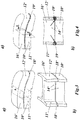
- FIG. 1-4 An example of such a configuration, which refers specifically to a turbine blade or its airfoil, is partially in the Fig. 1-4 played. That in the Fig. 1-4 illustrated basic component 10 '(in this case, an airfoil of a turbine blade) has a circumferential outer wall, which encloses an inner cavity 13'. The outer wall is subdivided into a pressure-side outer wall 11 'and a suction-side outer wall 12' (FIG. Fig. 1 a) , which merge at the edges of the airfoil.
- the base member 10 ' has on the upper side a connecting surface 15' ( Fig. 1 b) , which extends over the outer walls 11 'and 12' and the intermediate pieces 14 'and / or is formed by machine removal of blade material.
- a correspondingly shaped additional part 16' according to Fig. 2 as a replacement for the removed material or for the extension of the base member 10 'placed and connected to the base member 10' by a joining process.
- This is on the bottom of the attachment 16 'also a connecting surface 17' is formed, which corresponds to the connecting surface 15 'on the base member 10'.
- b is the additional part 16 'placed on the base member 10', wherein both parts with their connecting surfaces 15 'and 17' in a connection region 18 'abut each other and form a butt joint.
- Fig. 4a, b Both parts by a suitable joining process, in the present example by welding, with each other in the connection region 18 'materially connected, wherein as a connecting seam 19', a weld is formed.
- a medium flows transversely to the connection region between the intermediate pieces 14', in the region of portions in which the intermediate pieces 14 'are not materially connected, turbulences occur (see 21 in Fig. 10b ), which can locally reduce the cooling effect.
- the invention is based on a turbomachine component, comprising a base component and an additional part, each of which encloses an inner cavity with an outer wall, abut one another in the region of the outer wall with mutually coordinated connection surfaces in a connection region and are bonded to one another in the connection surfaces, wherein at least one wall-like intermediate piece is provided in the base component and / or in the additional part, which extends from the outer wall into the inner cavity. It is characterized in that at least one transition between the intermediate piece and the outer wall for the local degradation of mechanical and / or thermal stresses a section is arranged with a deviating from a straight line transition contour.
- the intermediate piece may be a rib, a connecting web, an intermediate wall or the like.
- the transition contour can take different forms.
- An embodiment of the invention is characterized in that in each case a wall-like intermediate piece is provided in the basic component and additional part is, wherein the wall-like intermediate pieces of both parts are aligned and abut each other in the connection area.
- a wall-like intermediate piece is provided only in the basic component or only in the additional part, so that in the connection area no opposite intermediate piece is present.
- basic component and additional part in the region of the intermediate pieces can be connected to each other at least partially cohesively. It is also conceivable that they are not connected to each other completely or cohesively.
- Another embodiment of the invention is advantageously characterized in that the wall-like intermediate piece (s) extends or extend through the inner cavity between two opposite sections of the outer wall, so that they support outer walls against each other and corresponding forces between transferred to the outer walls.
- the wall-like intermediate piece (s) it is likewise conceivable for the wall-like intermediate piece (s) to extend or extend from the outer wall into the inner cavity, without thereby reaching another section of the outer wall.
- the additional part is provided as a replacement for material removed from the basic component. This is the case in particular if the additional part is used to repair the basic component as a replacement for a recess made in the basic component.
- basic component and additional part may consist of different materials, if appropriate. Preferably, however, basic component and additional part of the same material.
- the basic component and the additional part are materially connected to one another by a suitable joining process.
- the joining process is arbitrary.
- welding and / or brazing and / or gluing can be used.
- the invention can be used when the component is a turbine blade.
- a further embodiment of the invention is characterized in that the voltage-reducing transition contour is designed to spring back relative to the connecting surfaces of the basic component or additional component. In this way, a mechanical decoupling between the outer walls and the intermediate piece is achieved in the connection area, can be significantly reduced by the mechanical and / or thermal stresses in this area.
- the stress-reducing transition contour is formed on the inside of the outer wall reset.
- the detailed course of the transition contour can be designed differently.
- the tension-reducing transition contour has returned at a predetermined distance to the level of the connecting surfaces.
- the stress-reducing transition contour in an arc in particular in the form of a quarter circle, can return to the level of the connecting surfaces.
- the stress-reducing transition contour can also return to the level of the bonding surfaces in a linear increase.
- the stress-relieving transition contour may remain at a level lowered from the bonding surfaces.
- the transition in the tension-reducing transition contour to the lowered level can also be done in a bow.
- transition of the voltage-reducing transition contour to the lowered level can be linear.
- such a transition contour can be provided at one or more transitions between the intermediate piece of the outer wall.
- the butt joint has a cross-sectional contour which deviates from a straight line oriented perpendicular to the intermediate piece in order to reduce flow turbulences occurring there.
- Such a deviation may consist in that the butt joint has a linear cross-sectional contour which is inclined to the intermediate piece.
- Such a cross-sectional contour is advantageous if the flow direction is opposite on both sides of the butt joint.
- the butt joint has a V-shaped cross-sectional contour, or that the butt joint has an arcuate cross-sectional contour.
- Such a cross-sectional contour is advantageous if the flow direction is the same on both sides of the butt joint.
- the crack-like mechanical and / or thermal voltage sources at the transition between the connecting region of the outer walls and the connecting portion of the intermediate pieces can be reduced or eliminated in their effectiveness by the geometry in this transition region by a section with a deviating from a straight transition contour is changed.
- Such a cutout is also advantageous if only a wall-like intermediate piece is provided either in the basic component or in the additional part.
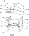
- a turbomachinery component is produced by positive connection between a base member 10 and an additional part 16.
- the two parts 10 and 16 each have a pressure-side outer wall 11 and a suction-side outer wall 12 and are joined to one another in a connection region 18 at associated connection surfaces 15 and 17.
- the connection is effected or by a connecting seam 19.
- the two parts 10 and 16 have in the inner cavity 13 in turn wall-like intermediate pieces 14 which abut each other with corresponding connecting surfaces.
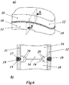
- transition contours 20 (FIG. Fig. 5b and 6b ) provided at the transitions between spacer 14 and outer wall 11 and 12, which are produced by recesses in the form of slot sections, that are composed of a straight section and a quarter circle.
- transition contours 20 can be used to reduce the stress, if the intermediate pieces 14 are completely or partially connected in the connecting region 18 cohesively with each other. But they can also be used if the intermediate pieces 14 are not interconnected, as in Fig. 6b is shown.
- transition contours 20 can be used as needed on the base member 10 and / or additional part 16 on one and / or the other outer wall.
- the transition contours can be curved, linear, polygonal or combined curved, linear and / or polygonal.
- transition contours of these embodiments with respect to the connecting surfaces 15, 17 of the base member 10 and the additional part 16 are designed to spring back.
- the transition contours can the inside of the outer wall 11, 12 may be formed reset (transition contours 20a, b, c and d in Fig. 7a-d ).
- transition contours at a predetermined distance from the outer wall 11, 12 to the level of the connecting surfaces 15, 17 return (transitional contours 20a-c in Fig. 7a-c ).
- This return can be curved in an arc, in particular in the form of a quarter circle (transition contour 20a in FIG Fig. 7a ).
- the transition contours can also return polygonal in a linear increase or abruptly to the level of the connecting surfaces 15, 17 (transition contour 20b, c in FIG Fig. 7b, c ).
- the stress-reducing transition contour remains on a plane lowered relative to the connecting surfaces 15, 17 (transition contour 20d-f in FIG Fig. 7d-f ), wherein the transition to the lowered level can take place in an abrupt (polygonal) manner (transition contour 20d in FIG Fig. 7d ) or curved in an arc (transition contour 20e in Fig. 7e ), or linear (transition contour 20 f in Fig. 7f ).
- one or more (in this example quadrant-like) transition contours 20a may be distributed in the turbomachinery component.
- crack-type voltage sources can each be formed by two opposite transition contours (20a in FIG Fig. 9b or f ) are completely eliminated, taking the example of Fig. 9f to the in Fig. 6 shown is equivalent and applies the invention to both the suction side and on the pressure side.
- transition contour 20a is optionally provided only on the base member 10 or additional part 16, a significant reduction of the mechanical and / or thermal stress can be achieved.
- transition contours improve the joining process of the parts 10 and 16 in total.
- a butt joint 23a is advantageous, which has an oblique to the intermediate piece 14 linear cross-sectional contour.
- the butt joint 23b has a V-shaped (polygonal) cross-sectional contour, or if the butt joint 23c has an arcuate (curved) cross-sectional contour.
- V-shaped (polygonal) cross-sectional contour or if the butt joint 23c has an arcuate (curved) cross-sectional contour.
- arcuate (curved) cross-sectional contour Of course, combined polygonal and curved cross-sectional contours are possible.
- the present invention is applicable to all turbomachinery components having internal hollow and wall-like spacers, such as e.g. Turbine blades, compressor blades, heat recovery segments, combustor components, carrier and housing parts.
Landscapes
- Engineering & Computer Science (AREA)
- Mechanical Engineering (AREA)
- General Engineering & Computer Science (AREA)
- Architecture (AREA)
- Structures Of Non-Positive Displacement Pumps (AREA)
- Turbine Rotor Nozzle Sealing (AREA)
- Pressure Welding/Diffusion-Bonding (AREA)
Applications Claiming Priority (1)
| Application Number | Priority Date | Filing Date | Title |
|---|---|---|---|
| CH00377/11A CH704616A1 (de) | 2011-03-07 | 2011-03-07 | Turbomaschinen-Bauteil. |
Publications (3)
| Publication Number | Publication Date |
|---|---|
| EP2497903A2 true EP2497903A2 (fr) | 2012-09-12 |
| EP2497903A3 EP2497903A3 (fr) | 2017-12-13 |
| EP2497903B1 EP2497903B1 (fr) | 2021-08-18 |
Family
ID=44123300
Family Applications (1)
| Application Number | Title | Priority Date | Filing Date |
|---|---|---|---|
| EP12157650.8A Active EP2497903B1 (fr) | 2011-03-07 | 2012-03-01 | Composant pour turbomachines |
Country Status (4)
| Country | Link |
|---|---|
| US (1) | US9074481B2 (fr) |
| EP (1) | EP2497903B1 (fr) |
| AU (1) | AU2012200535B2 (fr) |
| CH (1) | CH704616A1 (fr) |
Cited By (2)
| Publication number | Priority date | Publication date | Assignee | Title |
|---|---|---|---|---|
| EP2990598A1 (fr) * | 2014-08-27 | 2016-03-02 | Siemens Aktiengesellschaft | Aube de turbine et turbine |
| WO2018215519A1 (fr) * | 2017-05-23 | 2018-11-29 | Siemens Aktiengesellschaft | Procédé de fabrication d'une aube de turbine et aube de turbine |
Families Citing this family (3)
| Publication number | Priority date | Publication date | Assignee | Title |
|---|---|---|---|---|
| EP2948636B1 (fr) * | 2013-01-23 | 2019-03-06 | United Technologies Corporation | Composant de moteur à turbine à gaz ayant une extrémité de nervure profilée |
| US10519777B2 (en) | 2018-05-14 | 2019-12-31 | General Electric Company | Tip member for blade structure and related method to form turbomachine component |
| US11814979B1 (en) * | 2022-09-21 | 2023-11-14 | Rtx Corporation | Systems and methods of hybrid blade tip repair |
Citations (7)
| Publication number | Priority date | Publication date | Assignee | Title |
|---|---|---|---|---|
| US5060842A (en) | 1990-04-09 | 1991-10-29 | Westinghouse Electric Corp. | Method for refurbishing nozzle block vanes of a steam turbine |
| US5092942A (en) | 1989-03-28 | 1992-03-03 | Refurbished Turbine Components Limited | Method of repairing or modifying turbine blades |
| US5269057A (en) | 1991-12-24 | 1993-12-14 | Freedom Forge Corporation | Method of making replacement airfoil components |
| US5822852A (en) | 1997-07-14 | 1998-10-20 | General Electric Company | Method for replacing blade tips of directionally solidified and single crystal turbine blades |
| EP1143106A2 (fr) | 2000-04-03 | 2001-10-10 | United Technologies Corporation | Méthode et détail de réparation des aubes statoriques |
| US6508000B2 (en) | 2001-02-08 | 2003-01-21 | Siemens Westinghouse Power Corporation | Transient liquid phase bonding repair for advanced turbine blades and vanes |
| US6908288B2 (en) | 2001-10-31 | 2005-06-21 | General Electric Company | Repair of advanced gas turbine blades |
Family Cites Families (9)
| Publication number | Priority date | Publication date | Assignee | Title |
|---|---|---|---|---|
| DE908686C (de) * | 1942-04-09 | 1954-04-08 | Vorkauf Heinrich | Druckfeste Hohlschaufel fuer gekuehlte Gasturbinen |
| GB2254892A (en) * | 1991-04-16 | 1992-10-21 | Gen Electric | Hollow airfoil. |
| US7059834B2 (en) | 2003-01-24 | 2006-06-13 | United Technologies Corporation | Turbine blade |
| DE102006033799A1 (de) * | 2006-07-19 | 2008-01-24 | Mtu Aero Engines Gmbh | Verfahren zur Reparatur von Turbinenschaufeln |
| ATE457412T1 (de) * | 2006-10-20 | 2010-02-15 | Siemens Ag | Verfahren zur reparatur einer turbinenschaufel |
| US20080308610A1 (en) | 2007-06-15 | 2008-12-18 | United Technologies Corporation | Hollow structures formed with friction stir welding |
| US20100068550A1 (en) * | 2007-06-15 | 2010-03-18 | United Technologies Corporation | Hollow structures formed with friction stir welding |
| DE102008025848A1 (de) * | 2008-05-29 | 2009-12-03 | Mtu Aero Engines Gmbh | Verfahren zur Reparatur von einkristallinen Hochdruckturbinenschaufeln durch Diffusionslöten |
| CA2674905C (fr) * | 2008-06-11 | 2012-11-13 | Mitsubishi Heavy Industries, Ltd. | Joint a brides pour element structural |
-
2011
- 2011-03-07 CH CH00377/11A patent/CH704616A1/de not_active Application Discontinuation
-
2012
- 2012-01-31 AU AU2012200535A patent/AU2012200535B2/en not_active Ceased
- 2012-02-20 US US13/400,185 patent/US9074481B2/en not_active Expired - Fee Related
- 2012-03-01 EP EP12157650.8A patent/EP2497903B1/fr active Active
Patent Citations (7)
| Publication number | Priority date | Publication date | Assignee | Title |
|---|---|---|---|---|
| US5092942A (en) | 1989-03-28 | 1992-03-03 | Refurbished Turbine Components Limited | Method of repairing or modifying turbine blades |
| US5060842A (en) | 1990-04-09 | 1991-10-29 | Westinghouse Electric Corp. | Method for refurbishing nozzle block vanes of a steam turbine |
| US5269057A (en) | 1991-12-24 | 1993-12-14 | Freedom Forge Corporation | Method of making replacement airfoil components |
| US5822852A (en) | 1997-07-14 | 1998-10-20 | General Electric Company | Method for replacing blade tips of directionally solidified and single crystal turbine blades |
| EP1143106A2 (fr) | 2000-04-03 | 2001-10-10 | United Technologies Corporation | Méthode et détail de réparation des aubes statoriques |
| US6508000B2 (en) | 2001-02-08 | 2003-01-21 | Siemens Westinghouse Power Corporation | Transient liquid phase bonding repair for advanced turbine blades and vanes |
| US6908288B2 (en) | 2001-10-31 | 2005-06-21 | General Electric Company | Repair of advanced gas turbine blades |
Cited By (3)
| Publication number | Priority date | Publication date | Assignee | Title |
|---|---|---|---|---|
| EP2990598A1 (fr) * | 2014-08-27 | 2016-03-02 | Siemens Aktiengesellschaft | Aube de turbine et turbine |
| WO2016030449A1 (fr) * | 2014-08-27 | 2016-03-03 | Siemens Aktiengesellschaft | Aube de turbine et turbine |
| WO2018215519A1 (fr) * | 2017-05-23 | 2018-11-29 | Siemens Aktiengesellschaft | Procédé de fabrication d'une aube de turbine et aube de turbine |
Also Published As
| Publication number | Publication date |
|---|---|
| EP2497903B1 (fr) | 2021-08-18 |
| AU2012200535A1 (en) | 2012-09-27 |
| US9074481B2 (en) | 2015-07-07 |
| AU2012200535B2 (en) | 2016-01-28 |
| US20120230833A1 (en) | 2012-09-13 |
| EP2497903A3 (fr) | 2017-12-13 |
| CH704616A1 (de) | 2012-09-14 |
Similar Documents
| Publication | Publication Date | Title |
|---|---|---|
| EP2663414B1 (fr) | Procédé de fabrication générative d'un élément à système d'amortissement intégré pour turbomachine et élément à système d'amortissement intégré pour turbomachine fabriqué de façon générative | |
| EP3176370B1 (fr) | Ensemble d'aubes directrices pour turbomachine | |
| EP2497903B1 (fr) | Composant pour turbomachines | |
| EP2140114A2 (fr) | Palier axial notamment pour un turbocompresseur | |
| EP3067519B1 (fr) | Pale de soufflante pour une propulsion aéronautique | |
| EP2584146A1 (fr) | Procédé de fabrication d'une aube de rotor d'une turbomachine et aube de rotor correspondante | |
| EP2811118B1 (fr) | Segment d'aube directrice d'une turbomachine et turbine | |
| EP2410132A2 (fr) | Aube de compresseur d'une turbine à gaz équipée d'une structure du bord d'attaque autoaiguisante | |
| EP3483399A1 (fr) | Dispositif d'étanchéité pour une turbomachine, procédé de fabrication d'un dispositif d'étanchéité et turbomachine | |
| EP3056677B1 (fr) | Aube et turbomachine | |
| EP3581760B1 (fr) | Pale d'aube pour une turbomachine | |
| EP3704386B1 (fr) | Canal intermédiaire destiné à être placé entre un compresseur basse pression et un compresseur haute pression, produit par fabrication additive, ainsi que procédé de fabrication correspondant | |
| EP3647547A1 (fr) | Dispositif d'étanchéité pour une turbomachine et procédé de fabrication | |
| EP3039246B1 (fr) | Aube de turbine | |
| EP2496793B1 (fr) | Rotor soudé d'un compresseur de groupe motopropulseur de turbines à gaz | |
| EP2871418B1 (fr) | Chambre de combustion d'une turbine à gaz et son procédé de fabrication | |
| EP3514333B1 (fr) | Carénage d'extrémité d'aube de rotor pour une turbomachine, aube de rotor, procédé de fabrication d'un carénage d'extrémité d'aube de rotor et aube de rotor | |
| EP2454451B1 (fr) | Rotor avec éléments d'accouplement pour accoupler mécaniquement des aubes | |
| EP2860352A1 (fr) | Rotor, procédé de manufacture et aube associés | |
| EP2848770B1 (fr) | Pale de rotor d'une turbomachine axiale et élément d'amortissement | |
| DE102006016703A1 (de) | Verfahren zur Reparatur eines Leitschaufelsegments | |
| WO2018196957A1 (fr) | Aube de turbine dotée d'une partie céramique et procédé de fabrication ou de réparation d'une aube de turbine de ce type | |
| WO2010037659A1 (fr) | Aube pour une turbine à gaz | |
| DE102008047492A1 (de) | Geteilte Schaufel einer Turbinen- oder Verdichterstufe | |
| EP1914389A1 (fr) | Aube de turbine avec joint d'étanchéité séparé |
Legal Events
| Date | Code | Title | Description |
|---|---|---|---|
| PUAI | Public reference made under article 153(3) epc to a published international application that has entered the european phase |
Free format text: ORIGINAL CODE: 0009012 |
|
| AK | Designated contracting states |
Kind code of ref document: A2 Designated state(s): AL AT BE BG CH CY CZ DE DK EE ES FI FR GB GR HR HU IE IS IT LI LT LU LV MC MK MT NL NO PL PT RO RS SE SI SK SM TR |
|
| AX | Request for extension of the european patent |
Extension state: BA ME |
|
| RAP1 | Party data changed (applicant data changed or rights of an application transferred) |
Owner name: GENERAL ELECTRIC TECHNOLOGY GMBH |
|
| RAP1 | Party data changed (applicant data changed or rights of an application transferred) |
Owner name: ANSALDO ENERGIA IP UK LIMITED |
|
| PUAL | Search report despatched |
Free format text: ORIGINAL CODE: 0009013 |
|
| AK | Designated contracting states |
Kind code of ref document: A3 Designated state(s): AL AT BE BG CH CY CZ DE DK EE ES FI FR GB GR HR HU IE IS IT LI LT LU LV MC MK MT NL NO PL PT RO RS SE SI SK SM TR |
|
| AX | Request for extension of the european patent |
Extension state: BA ME |
|
| RIC1 | Information provided on ipc code assigned before grant |
Ipc: F01D 5/00 20060101AFI20171107BHEP |
|
| STAA | Information on the status of an ep patent application or granted ep patent |
Free format text: STATUS: REQUEST FOR EXAMINATION WAS MADE |
|
| 17P | Request for examination filed |
Effective date: 20180612 |
|
| RBV | Designated contracting states (corrected) |
Designated state(s): AL AT BE BG CH CY CZ DE DK EE ES FI FR GB GR HR HU IE IS IT LI LT LU LV MC MK MT NL NO PL PT RO RS SE SI SK SM TR |
|
| STAA | Information on the status of an ep patent application or granted ep patent |
Free format text: STATUS: EXAMINATION IS IN PROGRESS |
|
| 17Q | First examination report despatched |
Effective date: 20190731 |
|
| GRAP | Despatch of communication of intention to grant a patent |
Free format text: ORIGINAL CODE: EPIDOSNIGR1 |
|
| STAA | Information on the status of an ep patent application or granted ep patent |
Free format text: STATUS: GRANT OF PATENT IS INTENDED |
|
| INTG | Intention to grant announced |
Effective date: 20210310 |
|
| GRAS | Grant fee paid |
Free format text: ORIGINAL CODE: EPIDOSNIGR3 |
|
| GRAA | (expected) grant |
Free format text: ORIGINAL CODE: 0009210 |
|
| STAA | Information on the status of an ep patent application or granted ep patent |
Free format text: STATUS: THE PATENT HAS BEEN GRANTED |
|
| AK | Designated contracting states |
Kind code of ref document: B1 Designated state(s): AL AT BE BG CH CY CZ DE DK EE ES FI FR GB GR HR HU IE IS IT LI LT LU LV MC MK MT NL NO PL PT RO RS SE SI SK SM TR |
|
| REG | Reference to a national code |
Ref country code: GB Ref legal event code: FG4D Free format text: NOT ENGLISH |
|
| REG | Reference to a national code |
Ref country code: CH Ref legal event code: EP |
|
| REG | Reference to a national code |
Ref country code: DE Ref legal event code: R096 Ref document number: 502012016874 Country of ref document: DE |
|
| REG | Reference to a national code |
Ref country code: IE Ref legal event code: FG4D Free format text: LANGUAGE OF EP DOCUMENT: GERMAN Ref country code: AT Ref legal event code: REF Ref document number: 1421815 Country of ref document: AT Kind code of ref document: T Effective date: 20210915 |
|
| REG | Reference to a national code |
Ref country code: LT Ref legal event code: MG9D |
|
| REG | Reference to a national code |
Ref country code: NL Ref legal event code: MP Effective date: 20210818 |
|
| PG25 | Lapsed in a contracting state [announced via postgrant information from national office to epo] |
Ref country code: ES Free format text: LAPSE BECAUSE OF FAILURE TO SUBMIT A TRANSLATION OF THE DESCRIPTION OR TO PAY THE FEE WITHIN THE PRESCRIBED TIME-LIMIT Effective date: 20210818 Ref country code: FI Free format text: LAPSE BECAUSE OF FAILURE TO SUBMIT A TRANSLATION OF THE DESCRIPTION OR TO PAY THE FEE WITHIN THE PRESCRIBED TIME-LIMIT Effective date: 20210818 Ref country code: RS Free format text: LAPSE BECAUSE OF FAILURE TO SUBMIT A TRANSLATION OF THE DESCRIPTION OR TO PAY THE FEE WITHIN THE PRESCRIBED TIME-LIMIT Effective date: 20210818 Ref country code: NO Free format text: LAPSE BECAUSE OF FAILURE TO SUBMIT A TRANSLATION OF THE DESCRIPTION OR TO PAY THE FEE WITHIN THE PRESCRIBED TIME-LIMIT Effective date: 20211118 Ref country code: PT Free format text: LAPSE BECAUSE OF FAILURE TO SUBMIT A TRANSLATION OF THE DESCRIPTION OR TO PAY THE FEE WITHIN THE PRESCRIBED TIME-LIMIT Effective date: 20211220 Ref country code: LT Free format text: LAPSE BECAUSE OF FAILURE TO SUBMIT A TRANSLATION OF THE DESCRIPTION OR TO PAY THE FEE WITHIN THE PRESCRIBED TIME-LIMIT Effective date: 20210818 Ref country code: BG Free format text: LAPSE BECAUSE OF FAILURE TO SUBMIT A TRANSLATION OF THE DESCRIPTION OR TO PAY THE FEE WITHIN THE PRESCRIBED TIME-LIMIT Effective date: 20211118 Ref country code: SE Free format text: LAPSE BECAUSE OF FAILURE TO SUBMIT A TRANSLATION OF THE DESCRIPTION OR TO PAY THE FEE WITHIN THE PRESCRIBED TIME-LIMIT Effective date: 20210818 Ref country code: HR Free format text: LAPSE BECAUSE OF FAILURE TO SUBMIT A TRANSLATION OF THE DESCRIPTION OR TO PAY THE FEE WITHIN THE PRESCRIBED TIME-LIMIT Effective date: 20210818 |
|
| PG25 | Lapsed in a contracting state [announced via postgrant information from national office to epo] |
Ref country code: PL Free format text: LAPSE BECAUSE OF FAILURE TO SUBMIT A TRANSLATION OF THE DESCRIPTION OR TO PAY THE FEE WITHIN THE PRESCRIBED TIME-LIMIT Effective date: 20210818 Ref country code: LV Free format text: LAPSE BECAUSE OF FAILURE TO SUBMIT A TRANSLATION OF THE DESCRIPTION OR TO PAY THE FEE WITHIN THE PRESCRIBED TIME-LIMIT Effective date: 20210818 Ref country code: GR Free format text: LAPSE BECAUSE OF FAILURE TO SUBMIT A TRANSLATION OF THE DESCRIPTION OR TO PAY THE FEE WITHIN THE PRESCRIBED TIME-LIMIT Effective date: 20211119 |
|
| PG25 | Lapsed in a contracting state [announced via postgrant information from national office to epo] |
Ref country code: NL Free format text: LAPSE BECAUSE OF FAILURE TO SUBMIT A TRANSLATION OF THE DESCRIPTION OR TO PAY THE FEE WITHIN THE PRESCRIBED TIME-LIMIT Effective date: 20210818 |
|
| PG25 | Lapsed in a contracting state [announced via postgrant information from national office to epo] |
Ref country code: DK Free format text: LAPSE BECAUSE OF FAILURE TO SUBMIT A TRANSLATION OF THE DESCRIPTION OR TO PAY THE FEE WITHIN THE PRESCRIBED TIME-LIMIT Effective date: 20210818 |
|
| REG | Reference to a national code |
Ref country code: DE Ref legal event code: R097 Ref document number: 502012016874 Country of ref document: DE |
|
| PG25 | Lapsed in a contracting state [announced via postgrant information from national office to epo] |
Ref country code: SM Free format text: LAPSE BECAUSE OF FAILURE TO SUBMIT A TRANSLATION OF THE DESCRIPTION OR TO PAY THE FEE WITHIN THE PRESCRIBED TIME-LIMIT Effective date: 20210818 Ref country code: SK Free format text: LAPSE BECAUSE OF FAILURE TO SUBMIT A TRANSLATION OF THE DESCRIPTION OR TO PAY THE FEE WITHIN THE PRESCRIBED TIME-LIMIT Effective date: 20210818 Ref country code: RO Free format text: LAPSE BECAUSE OF FAILURE TO SUBMIT A TRANSLATION OF THE DESCRIPTION OR TO PAY THE FEE WITHIN THE PRESCRIBED TIME-LIMIT Effective date: 20210818 Ref country code: EE Free format text: LAPSE BECAUSE OF FAILURE TO SUBMIT A TRANSLATION OF THE DESCRIPTION OR TO PAY THE FEE WITHIN THE PRESCRIBED TIME-LIMIT Effective date: 20210818 Ref country code: CZ Free format text: LAPSE BECAUSE OF FAILURE TO SUBMIT A TRANSLATION OF THE DESCRIPTION OR TO PAY THE FEE WITHIN THE PRESCRIBED TIME-LIMIT Effective date: 20210818 Ref country code: AL Free format text: LAPSE BECAUSE OF FAILURE TO SUBMIT A TRANSLATION OF THE DESCRIPTION OR TO PAY THE FEE WITHIN THE PRESCRIBED TIME-LIMIT Effective date: 20210818 |
|
| PLBE | No opposition filed within time limit |
Free format text: ORIGINAL CODE: 0009261 |
|
| STAA | Information on the status of an ep patent application or granted ep patent |
Free format text: STATUS: NO OPPOSITION FILED WITHIN TIME LIMIT |
|
| 26N | No opposition filed |
Effective date: 20220519 |
|
| PG25 | Lapsed in a contracting state [announced via postgrant information from national office to epo] |
Ref country code: IT Free format text: LAPSE BECAUSE OF FAILURE TO SUBMIT A TRANSLATION OF THE DESCRIPTION OR TO PAY THE FEE WITHIN THE PRESCRIBED TIME-LIMIT Effective date: 20210818 |
|
| PG25 | Lapsed in a contracting state [announced via postgrant information from national office to epo] |
Ref country code: SI Free format text: LAPSE BECAUSE OF FAILURE TO SUBMIT A TRANSLATION OF THE DESCRIPTION OR TO PAY THE FEE WITHIN THE PRESCRIBED TIME-LIMIT Effective date: 20210818 |
|
| PG25 | Lapsed in a contracting state [announced via postgrant information from national office to epo] |
Ref country code: MC Free format text: LAPSE BECAUSE OF FAILURE TO SUBMIT A TRANSLATION OF THE DESCRIPTION OR TO PAY THE FEE WITHIN THE PRESCRIBED TIME-LIMIT Effective date: 20210818 |
|
| REG | Reference to a national code |
Ref country code: CH Ref legal event code: PL |
|
| GBPC | Gb: european patent ceased through non-payment of renewal fee |
Effective date: 20220301 |
|
| REG | Reference to a national code |
Ref country code: BE Ref legal event code: MM Effective date: 20220331 |
|
| PG25 | Lapsed in a contracting state [announced via postgrant information from national office to epo] |
Ref country code: LU Free format text: LAPSE BECAUSE OF NON-PAYMENT OF DUE FEES Effective date: 20220301 Ref country code: LI Free format text: LAPSE BECAUSE OF NON-PAYMENT OF DUE FEES Effective date: 20220331 Ref country code: IE Free format text: LAPSE BECAUSE OF NON-PAYMENT OF DUE FEES Effective date: 20220301 Ref country code: GB Free format text: LAPSE BECAUSE OF NON-PAYMENT OF DUE FEES Effective date: 20220301 Ref country code: FR Free format text: LAPSE BECAUSE OF NON-PAYMENT OF DUE FEES Effective date: 20220331 Ref country code: CH Free format text: LAPSE BECAUSE OF NON-PAYMENT OF DUE FEES Effective date: 20220331 |
|
| PG25 | Lapsed in a contracting state [announced via postgrant information from national office to epo] |
Ref country code: BE Free format text: LAPSE BECAUSE OF NON-PAYMENT OF DUE FEES Effective date: 20220331 |
|
| REG | Reference to a national code |
Ref country code: AT Ref legal event code: MM01 Ref document number: 1421815 Country of ref document: AT Kind code of ref document: T Effective date: 20220301 |
|
| PG25 | Lapsed in a contracting state [announced via postgrant information from national office to epo] |
Ref country code: AT Free format text: LAPSE BECAUSE OF NON-PAYMENT OF DUE FEES Effective date: 20220301 |
|
| PG25 | Lapsed in a contracting state [announced via postgrant information from national office to epo] |
Ref country code: HU Free format text: LAPSE BECAUSE OF FAILURE TO SUBMIT A TRANSLATION OF THE DESCRIPTION OR TO PAY THE FEE WITHIN THE PRESCRIBED TIME-LIMIT; INVALID AB INITIO Effective date: 20120301 |
|
| PG25 | Lapsed in a contracting state [announced via postgrant information from national office to epo] |
Ref country code: MK Free format text: LAPSE BECAUSE OF FAILURE TO SUBMIT A TRANSLATION OF THE DESCRIPTION OR TO PAY THE FEE WITHIN THE PRESCRIBED TIME-LIMIT Effective date: 20210818 Ref country code: CY Free format text: LAPSE BECAUSE OF FAILURE TO SUBMIT A TRANSLATION OF THE DESCRIPTION OR TO PAY THE FEE WITHIN THE PRESCRIBED TIME-LIMIT Effective date: 20210818 |
|
| P01 | Opt-out of the competence of the unified patent court (upc) registered |
Effective date: 20240430 |
|
| PG25 | Lapsed in a contracting state [announced via postgrant information from national office to epo] |
Ref country code: MT Free format text: LAPSE BECAUSE OF FAILURE TO SUBMIT A TRANSLATION OF THE DESCRIPTION OR TO PAY THE FEE WITHIN THE PRESCRIBED TIME-LIMIT Effective date: 20210818 |
|
| PG25 | Lapsed in a contracting state [announced via postgrant information from national office to epo] |
Ref country code: TR Free format text: LAPSE BECAUSE OF FAILURE TO SUBMIT A TRANSLATION OF THE DESCRIPTION OR TO PAY THE FEE WITHIN THE PRESCRIBED TIME-LIMIT Effective date: 20210818 |
|
| PGFP | Annual fee paid to national office [announced via postgrant information from national office to epo] |
Ref country code: DE Payment date: 20260320 Year of fee payment: 15 |