EP2497934B1 - Système d'évacuation de flux pour moteur d'avion - Google Patents
Système d'évacuation de flux pour moteur d'avion Download PDFInfo
- Publication number
- EP2497934B1 EP2497934B1 EP11382059.1A EP11382059A EP2497934B1 EP 2497934 B1 EP2497934 B1 EP 2497934B1 EP 11382059 A EP11382059 A EP 11382059A EP 2497934 B1 EP2497934 B1 EP 2497934B1
- Authority
- EP
- European Patent Office
- Prior art keywords
- flow
- engine
- fins
- evacuation system
- nozzle
- Prior art date
- Legal status (The legal status is an assumption and is not a legal conclusion. Google has not performed a legal analysis and makes no representation as to the accuracy of the status listed.)
- Active
Links
Images


Classifications
-
- F—MECHANICAL ENGINEERING; LIGHTING; HEATING; WEAPONS; BLASTING
- F02—COMBUSTION ENGINES; HOT-GAS OR COMBUSTION-PRODUCT ENGINE PLANTS
- F02K—JET-PROPULSION PLANTS
- F02K1/00—Plants characterised by the form or arrangement of the jet pipe or nozzle; Jet pipes or nozzles peculiar thereto
- F02K1/46—Nozzles having means for adding air to the jet or for augmenting the mixing region between the jet and the ambient air, e.g. for silencing
-
- F—MECHANICAL ENGINEERING; LIGHTING; HEATING; WEAPONS; BLASTING
- F02—COMBUSTION ENGINES; HOT-GAS OR COMBUSTION-PRODUCT ENGINE PLANTS
- F02K—JET-PROPULSION PLANTS
- F02K1/00—Plants characterised by the form or arrangement of the jet pipe or nozzle; Jet pipes or nozzles peculiar thereto
- F02K1/38—Introducing air inside the jet
- F02K1/386—Introducing air inside the jet mixing devices in the jet pipe, e.g. for mixing primary and secondary flow
-
- F—MECHANICAL ENGINEERING; LIGHTING; HEATING; WEAPONS; BLASTING
- F05—INDEXING SCHEMES RELATING TO ENGINES OR PUMPS IN VARIOUS SUBCLASSES OF CLASSES F01-F04
- F05D—INDEXING SCHEME FOR ASPECTS RELATING TO NON-POSITIVE-DISPLACEMENT MACHINES OR ENGINES, GAS-TURBINES OR JET-PROPULSION PLANTS
- F05D2260/00—Function
- F05D2260/20—Heat transfer, e.g. cooling
- F05D2260/221—Improvement of heat transfer
- F05D2260/2212—Improvement of heat transfer by creating turbulence
-
- Y—GENERAL TAGGING OF NEW TECHNOLOGICAL DEVELOPMENTS; GENERAL TAGGING OF CROSS-SECTIONAL TECHNOLOGIES SPANNING OVER SEVERAL SECTIONS OF THE IPC; TECHNICAL SUBJECTS COVERED BY FORMER USPC CROSS-REFERENCE ART COLLECTIONS [XRACs] AND DIGESTS
- Y02—TECHNOLOGIES OR APPLICATIONS FOR MITIGATION OR ADAPTATION AGAINST CLIMATE CHANGE
- Y02T—CLIMATE CHANGE MITIGATION TECHNOLOGIES RELATED TO TRANSPORTATION
- Y02T50/00—Aeronautics or air transport
- Y02T50/60—Efficient propulsion technologies, e.g. for aircraft
Definitions
- the present invention relates to the flow evacuation system of an aircraft gas turbine engine and, more in particular, of a turboprop or a turboshaft engine.
- a typical turboprop engine comprises a core engine that includes a compressor section, a combustor and a first turbine in serial flow relationship, and a power turbine located aft the first turbine. Pressurized air from the compressor section is mixed with fuel and burned in the combustor to produce a high energy gas stream. The power turbine extracts energy from the gas stream to power the propeller.
- the engine also includes a nozzle which drives this flow outwards the engine.
- US 2007/0089398 disclose a flow evacuation system with an eductor having a plurality of flow straighteners configured to reduce swirl motion of the gas that flows therethrough in order to avoid that a portion of exhaust gases may swirl within the eductor but may not flow out the eductor outlet.
- GB1045295 discloses a noise suppression device for reducing the noise generated by a high velocity gaseous jet issuing into the ambient atmosphere which comprises a nozzle having vanes to impart rotation to the gaseous jet issuing from the nozzle and an ejector shroud disposed about the nozzle.
- thermodynamically and aerodynamically dissimilar fluids in swirling flow relationship to accelerate mixing and hence combustion in the combustion zone.
- the present invention is intended to the solution of this problem.
- An object of the present invention is to provide an efficient flow evacuation system for an aircraft engine, particularly for a turboprop or a turboshaft engine, in a variety of operating conditions.
- Another object of the present invention is to provide a flow evacuation system for an aircraft engine, particularly for a turboprop or a turboshaft engine, with a high ventilation capacity.
- a flow evacuation system for an aircraft engine comprising an engine nozzle that conveys the engine exhaust flow and an eductor receiving said engine exhaust flow and the engine ventilation flow, the engine nozzle having a final section in contact by its outer surface with said ventilation flow, the engine exhaust flow having a low swirl when the engine operates under design conditions and a high swirl when the engine operates out of design conditions, the engine nozzle comprising a plurality of local flow conditioners placed in its inner surface in said final section for reducing the swirl of the engine exhaust flow at the exit of the engine nozzle, for producing further depression to improve the suction effects over the ventilation flow and for facilitating the mixture of the engine exhaust flow and the ventilation flow, enhancing its evacuation along the eductor.
- said local flow conditioners are fins oriented radially, fins oriented with predetermined angular deviation with respect to a radial orientation or fins oriented with a variable angular deviation with respect to a radial orientation. Therefore some fins orientation choices are provided for a better accommodation to the flow evacuation needs of each engine.
- said local flow conditioners are fins distributed along the full final section of the engine nozzle or fins distributed along a sector of the final section of the engine nozzle, preferably, in both cases, in an equally spaced distribution. Therefore some fin distribution choices are provided for a better accommodation to the flow evacuation needs of each engine.
- said fins are flat plates, curved plates or airfoil-shaped bodies. Therefore some fin configuration choices are provided for a better accommodation to the flow evacuation needs of each engine.
- said flat plates have a rectangular or a trapezoidal shape, being the inclined side its leading edge with respect to the engine exhaust flow.
- an aircraft engine comprising a flow evacuation system having the abovementioned features, being said engine a turboshaft engine or a turboprop engine.
- An aircraft engine housed in a nacelle, requires a cooling and ventilation system to reduce the high temperatures generated within the engine bay under acceptable limits.
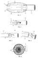
- this flow evacuation system is based on the fact that the higher energy or primary flow (the engine exhaust flow 11) suctions the lower energy or secondary flow (the ventilation flow 13) to help ventilation through the engine bay 19.
- the parameters which define the engine exhaust flow 11 must lie between certain limits.
- An ideal condition for the engine exhaust flow 11 along the engine nozzle 31 is, as shown in Figure 2 , zero swirl.
- the velocity of the engine exhaust flow 11 in the exit of the engine nozzle 31 has then only an axial component V axial .
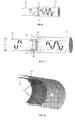
- the engine exhaust flow 11 has usually a certain swirl as shown in Figures 3 and 4 for straight and curved engine nozzles 31. Therefore the velocity of the engine exhaust flow 11 in the exit of the engine nozzle 31 has an axial component V axial and a tangential component V t , which involves, for a high swirl, the flow pressure distribution shown in Figure 5 with high total pressure areas 38 near the engine nozzle wall.
- an excessive swirl of the engine exhaust flow 11 at the engine nozzle exit can prevent the correct suction of the ventilation flow 13 by the engine exhaust flow 11, blocking the nacelle ventilation flow 13 and possibly causing the reingestion of exhaust engine gases 11 towards the ventilation bay of the aircraft engine as shown in Figure 6 .
- a design objective of an aircraft engine is the avoidance of said swirl in those engine operating conditions which imply greater fuel consumption.
- Typical aircraft engine configuration restrictions for example a propeller/power turbine group rotating at a constant speed
- the swirl of the engine exhaust flow 11 through the engine nozzle 31 increases, the performance of the engine decreases in terms of residual thrust, ventilation capacity and/or increase in fuel consumption.
- said mitigation is achieved as shown in Figure 7 by means of a plurality of local flow conditioners 41 installed in the wetted surface of the engine nozzle 31 in its final section 32 to condition the engine exhaust flow 11 leaving the engine nozzle 31 in the area 35 in which the ventilation flow 13 is discharged into the eductor 33.
- said local flow conditioners are, as shown in Figures 8-10 a plurality of small fins 41 fixed to the wetted surface of the exhaust nozzle 31, oriented according to the pattern of an engine exhaust flow 11 without swirl, i.e. a radial orientation.
- said small fins 41 do not interfere with the engine exhaust flow 11 so energy losses in said flow are minimized.
- the effect of said fins 41 is the local conditioning of the engine exhaust flow 11 leaving the engine nozzle 31 in the area 35 enhancing the ventilation flow 13 due to:
- said small fins 41 have an orientation deviated with respect to the radial orientation of Figure 10 , whether a predetermined angular deviation as shown in Figure 11 or a variable angular deviation as shown in Figure 12 , for a better accommodation to the operating conditions expected for each engine.
- Said fins 41 are normally distributed along the full final section of the nozzle 31 as shown in Figures 10-12 , preferably in an equally spaced distribution, but they can be distributed only in one sector of the nozzle 31, as shown in Figure 13 , if the ventilation needs in the area not covered by said fins 41 do not require a mitigation of the effects of an engine exhaust flow 11 with a high swirl.
- said fins 41 are configured as flat plates as shown in Figure 14 , as curved plates as shown in Figure 15 or as airfoil-shaped bodies as shown in Figure 16 .
- a suitable election of the fins shape for a particular engine may achieve an optimization of the evacuation of the engine exhaust flow 11 and/or of the ventilation of the engine nacelle.
- said fins 41 are flat plates of a rectangular or a trapezoidal shape (see Figures 17 and 18 ) with a height H comprised between D/20 and D/10, being D the diameter of the engine nozzle 31 in said final section 32, and a length L comprised between 2H and 4H, that are placed a distance S to the engine nozzle outlet comprised between H and 3H.
- An advantage of the present invention is that it provides passive means that enable a significant reduction in the swirl of the engine exhaust flow in operating conditions outside the design conditions, thus increasing the flow evacuation system capacity to boost the ventilation flow.
- Another advantage of the present invention is that said local flow conditioners also contribute to an efficient mixing of the engine exhaust flow and the ventilation flow due to the local vorticity and local suction effects produced in the engine exhaust flow by said local flow conditioners.
Landscapes
- Engineering & Computer Science (AREA)
- Chemical & Material Sciences (AREA)
- Combustion & Propulsion (AREA)
- Mechanical Engineering (AREA)
- General Engineering & Computer Science (AREA)
- Jet Pumps And Other Pumps (AREA)
- Exhaust Gas After Treatment (AREA)
Claims (12)
- Système d'évacuation d'écoulement pour un moteur d'aéronef, comprenant une buse de moteur (31) qui convoie l'écoulement d'échappement de moteur (11) et un éducteur (33) recevant ledit écoulement d'échappement de moteur (11) et un écoulement de ventilation de moteur (13), l'éducteur (33) étant un conduit dans lequel le mélange entre l'écoulement d'échappement de moteur et l'écoulement de ventilation s'effectue, et qui est configuré de telle sorte qu'une partie de l'énergie de l'écoulement d'échappement de moteur soit transmise à l'écoulement de ventilation pour une meilleure ventilation du moteur, la buse de moteur (31) comportant une section finale (32) en contact par sa surface radiale extérieure avec ledit écoulement de ventilation (13), l'écoulement d'échappement de moteur (11) ayant un faible tourbillonnement lorsque le moteur fonctionne dans des conditions nominales et un tourbillonnement élevé lorsque le moteur fonctionne en dehors des conditions nominales, caractérisé en ce que ladite buse de moteur (31) comprend une pluralité de dispositifs de conditionnement d'écoulement local (41), qui sont des ailettes orientées radialement ou des ailettes orientées avec une déviation angulaire prédéterminée ou variable par rapport à une orientation radiale, disposées dans sa surface radiale intérieure dans ladite section finale (32), configurées de telle sorte qu'elles réduisent le tourbillonnement de l'écoulement d'échappement de moteur (11) à la sortie de la buse de moteur (31), afin de produire une dépression supplémentaire de façon à améliorer les effets d'aspiration sur l'écoulement de ventilation (13), et afin de faciliter le mélange de l'écoulement d'échappement de moteur (11) et de l'écoulement de ventilation (13), améliorant son évacuation le long de l'éducteur (33).
- Système d'évacuation d'écoulement selon l'une quelconque de la revendication 1, dans lequel lesdits dispositifs de conditionnement d'écoulement local (41) sont des ailettes réparties le long de la totalité de la section finale (32) de la buse de moteur (31).
- Système d'évacuation d'écoulement selon l'une quelconque des revendications 1 à 2, dans lequel lesdits dispositifs de conditionnement d'écoulement local (41) sont des ailettes réparties le long d'un secteur de la section finale (32) de la buse de moteur (31).
- Système d'évacuation d'écoulement selon l'une quelconque des revendications 2 à 3, dans lequel la répartition desdits dispositifs de conditionnement d'écoulement local (41) est une répartition également espacée.
- Système d'évacuation d'écoulement selon l'une quelconque des revendications 1 à 4, dans lequel lesdites ailettes (41) sont des plaques plates.
- Système d'évacuation d'écoulement selon la revendication 5, dans lequel lesdites ailettes (41) ont une forme rectangulaire.
- Système d'évacuation d'écoulement selon la revendication 5, dans lequel lesdites ailettes (41) ont une forme trapézoïdale, le côté de leur bord avant étant incliné par rapport à l'écoulement d'échappement de moteur (11).
- Système d'évacuation d'écoulement selon l'une quelconque des revendications 6 à 7, dans lequel :- la hauteur H desdites ailettes (41) est comprise entre D/20 et D/10, D étant le diamètre de la buse de moteur (31) dans ladite section finale (32) ;- la longueur L desdites ailettes (41) est comprise entre 2H et 4H ;- la distance S desdites ailettes (41) à l'orifice de sortie de buse de moteur est comprise entre H et 3H.
- Système d'évacuation d'écoulement selon l'une quelconque des revendications 1 à 4, dans lequel lesdites ailettes (41) sont des plaques incurvées.
- Système d'évacuation d'écoulement selon l'une quelconque des revendications 1 à 4, dans lequel lesdites ailettes (41) sont des corps en forme de profil aérodynamique.
- Moteur d'aéronef comprenant un système d'évacuation d'écoulement selon l'une quelconque des revendications 1 à 10, dans lequel ledit moteur est un moteur à turbomoteur.
- Moteur d'aéronef comprenant un système d'évacuation d'écoulement selon l'une quelconque des revendications 1 à 10, dans lequel ledit moteur est un moteur à turbopropulseur.
Priority Applications (3)
| Application Number | Priority Date | Filing Date | Title |
|---|---|---|---|
| EP11382059.1A EP2497934B1 (fr) | 2011-03-07 | 2011-03-07 | Système d'évacuation de flux pour moteur d'avion |
| ES11382059.1T ES2488404T3 (es) | 2011-03-07 | 2011-03-07 | Sistema de evacuación de flujo para un motor de aeronave |
| US13/413,324 US20120279225A1 (en) | 2011-03-07 | 2012-03-06 | Flow evacuation system for an aircraft engine |
Applications Claiming Priority (1)
| Application Number | Priority Date | Filing Date | Title |
|---|---|---|---|
| EP11382059.1A EP2497934B1 (fr) | 2011-03-07 | 2011-03-07 | Système d'évacuation de flux pour moteur d'avion |
Publications (2)
| Publication Number | Publication Date |
|---|---|
| EP2497934A1 EP2497934A1 (fr) | 2012-09-12 |
| EP2497934B1 true EP2497934B1 (fr) | 2014-04-30 |
Family
ID=44343143
Family Applications (1)
| Application Number | Title | Priority Date | Filing Date |
|---|---|---|---|
| EP11382059.1A Active EP2497934B1 (fr) | 2011-03-07 | 2011-03-07 | Système d'évacuation de flux pour moteur d'avion |
Country Status (3)
| Country | Link |
|---|---|
| US (1) | US20120279225A1 (fr) |
| EP (1) | EP2497934B1 (fr) |
| ES (1) | ES2488404T3 (fr) |
Families Citing this family (3)
| Publication number | Priority date | Publication date | Assignee | Title |
|---|---|---|---|---|
| US20130087632A1 (en) * | 2011-10-11 | 2013-04-11 | Patrick Germain | Gas turbine engine exhaust ejector nozzle with de-swirl cascade |
| US11268390B2 (en) * | 2018-07-19 | 2022-03-08 | Sikorsky Aircraft Corporation | Vortex generators for turbine engine exhaust |
| US20250382066A1 (en) * | 2024-06-18 | 2025-12-18 | Pratt & Whitney Canada Corp. | Gas turbine engine exhaust nozzle |
Family Cites Families (14)
| Publication number | Priority date | Publication date | Assignee | Title |
|---|---|---|---|---|
| US2648192A (en) * | 1949-09-27 | 1953-08-11 | United Aircraft Corp | Variable capacity jet exhaust augmenter |
| US3161257A (en) * | 1959-05-01 | 1964-12-15 | Young Alec David | Jet pipe nozzle silencers |
| GB1045295A (en) * | 1964-03-25 | 1966-10-12 | Peter Bradshaw | Improvements in or relating to a jet noise suppression device |
| US3788065A (en) * | 1970-10-26 | 1974-01-29 | United Aircraft Corp | Annular combustion chamber for dissimilar fluids in swirling flow relationship |
| US4298089A (en) * | 1976-12-23 | 1981-11-03 | The Boeing Company | Vortex generators for internal mixing in a turbofan engine |
| US4215536A (en) * | 1978-12-26 | 1980-08-05 | The Boeing Company | Gas turbine mixer apparatus |
| AU2443884A (en) * | 1983-02-15 | 1984-08-23 | Commonwealth Of Australia, The | Thrust augmentor |
| US6314721B1 (en) * | 1998-09-04 | 2001-11-13 | United Technologies Corporation | Tabbed nozzle for jet noise suppression |
| US6487848B2 (en) * | 1998-11-06 | 2002-12-03 | United Technologies Corporation | Gas turbine engine jet noise suppressor |
| JP4743465B2 (ja) * | 2001-04-19 | 2011-08-10 | 株式会社Ihi | ジェットエンジン用ローブミキサー |
| JP4061574B2 (ja) * | 2002-04-25 | 2008-03-19 | 株式会社Ihi | ガスタービン用のローブミキサ |
| JP4513714B2 (ja) | 2005-10-21 | 2010-07-28 | トヨタ自動車株式会社 | 触媒劣化検出方法 |
| US7500353B2 (en) * | 2005-10-25 | 2009-03-10 | Honeywell International Inc. | Eductor swirl buster |
| US7966825B2 (en) * | 2006-10-31 | 2011-06-28 | Honeywell International Inc. | Exhaust eductor system with a recirculation baffle |
-
2011
- 2011-03-07 ES ES11382059.1T patent/ES2488404T3/es active Active
- 2011-03-07 EP EP11382059.1A patent/EP2497934B1/fr active Active
-
2012
- 2012-03-06 US US13/413,324 patent/US20120279225A1/en not_active Abandoned
Also Published As
| Publication number | Publication date |
|---|---|
| EP2497934A1 (fr) | 2012-09-12 |
| ES2488404T3 (es) | 2014-08-27 |
| US20120279225A1 (en) | 2012-11-08 |
Similar Documents
| Publication | Publication Date | Title |
|---|---|---|
| US7402026B2 (en) | Turbine exhaust strut airfoil profile | |
| US7559747B2 (en) | Turbine exhaust strut airfoil profile | |
| CN109668174B (zh) | 燃气涡轮发动机的驻涡燃烧器及其操作方法 | |
| EP2196634B1 (fr) | Ventilation d'une cavité | |
| EP2660424B1 (fr) | Conduits inter-turbine avec rapports de surfaces variables | |
| IT202000002272A1 (it) | Scatola ingranaggi per un motore | |
| EP3171009B1 (fr) | Capot de compression pour échappement de moteur à réaction | |
| EP2568119B1 (fr) | Aube de turbine avec agencement de refroidissement du bord de fuite amélioré | |
| EP2239428A2 (fr) | Plénum d'échappement pour moteur à turbine | |
| US20160273363A1 (en) | Engine component | |
| US11131205B2 (en) | Inter-turbine ducts with flow control mechanisms | |
| US12492642B2 (en) | Outlet guide vane assembly for a turbofan engine | |
| EP2554793A2 (fr) | Conduits inter-turbines dotés d'aubes directrices d'un moteur à turbine à gaz | |
| US12286901B2 (en) | Turbine engine component with deflector | |
| EP2497934B1 (fr) | Système d'évacuation de flux pour moteur d'avion | |
| US12276199B2 (en) | Outlet guide vane assembly for a turbofan engine | |
| EP3354848B1 (fr) | Conduits inter-turbine avec de multiples pales séparatrices | |
| EP4400707A1 (fr) | Mélangeur d'échappement doté de saillies | |
| US12442315B2 (en) | Gas turbine engine | |
| GB2595482A (en) | Aircraft propulsor |
Legal Events
| Date | Code | Title | Description |
|---|---|---|---|
| PUAI | Public reference made under article 153(3) epc to a published international application that has entered the european phase |
Free format text: ORIGINAL CODE: 0009012 |
|
| AK | Designated contracting states |
Kind code of ref document: A1 Designated state(s): AL AT BE BG CH CY CZ DE DK EE ES FI FR GB GR HR HU IE IS IT LI LT LU LV MC MK MT NL NO PL PT RO RS SE SI SK SM TR |
|
| AX | Request for extension of the european patent |
Extension state: BA ME |
|
| 17P | Request for examination filed |
Effective date: 20130312 |
|
| RIC1 | Information provided on ipc code assigned before grant |
Ipc: F02K 1/46 20060101ALI20130930BHEP Ipc: F02K 1/38 20060101AFI20130930BHEP |
|
| GRAP | Despatch of communication of intention to grant a patent |
Free format text: ORIGINAL CODE: EPIDOSNIGR1 |
|
| INTG | Intention to grant announced |
Effective date: 20131125 |
|
| RIN1 | Information on inventor provided before grant (corrected) |
Inventor name: MARISCAL SANCHEZ, FRANCISCO JAVIER Inventor name: IBANEZ COLAS, VICENTE Inventor name: ANGEL BLASCO, EMILIO JAVIER Inventor name: PERDONES DIAZ, DAVID Inventor name: GONZALEZ BIEDMA, CARLOS |
|
| GRAS | Grant fee paid |
Free format text: ORIGINAL CODE: EPIDOSNIGR3 |
|
| GRAA | (expected) grant |
Free format text: ORIGINAL CODE: 0009210 |
|
| AK | Designated contracting states |
Kind code of ref document: B1 Designated state(s): AL AT BE BG CH CY CZ DE DK EE ES FI FR GB GR HR HU IE IS IT LI LT LU LV MC MK MT NL NO PL PT RO RS SE SI SK SM TR |
|
| REG | Reference to a national code |
Ref country code: GB Ref legal event code: FG4D Ref country code: CH Ref legal event code: EP |
|
| REG | Reference to a national code |
Ref country code: AT Ref legal event code: REF Ref document number: 665321 Country of ref document: AT Kind code of ref document: T Effective date: 20140515 |
|
| REG | Reference to a national code |
Ref country code: IE Ref legal event code: FG4D |
|
| REG | Reference to a national code |
Ref country code: DE Ref legal event code: R096 Ref document number: 602011006532 Country of ref document: DE Effective date: 20140612 |
|
| REG | Reference to a national code |
Ref country code: ES Ref legal event code: FG2A Ref document number: 2488404 Country of ref document: ES Kind code of ref document: T3 Effective date: 20140827 |
|
| REG | Reference to a national code |
Ref country code: AT Ref legal event code: MK05 Ref document number: 665321 Country of ref document: AT Kind code of ref document: T Effective date: 20140430 |
|
| REG | Reference to a national code |
Ref country code: LT Ref legal event code: MG4D |
|
| REG | Reference to a national code |
Ref country code: NL Ref legal event code: VDEP Effective date: 20140430 |
|
| PG25 | Lapsed in a contracting state [announced via postgrant information from national office to epo] |
Ref country code: BG Free format text: LAPSE BECAUSE OF FAILURE TO SUBMIT A TRANSLATION OF THE DESCRIPTION OR TO PAY THE FEE WITHIN THE PRESCRIBED TIME-LIMIT Effective date: 20140730 Ref country code: IS Free format text: LAPSE BECAUSE OF FAILURE TO SUBMIT A TRANSLATION OF THE DESCRIPTION OR TO PAY THE FEE WITHIN THE PRESCRIBED TIME-LIMIT Effective date: 20140830 Ref country code: GR Free format text: LAPSE BECAUSE OF FAILURE TO SUBMIT A TRANSLATION OF THE DESCRIPTION OR TO PAY THE FEE WITHIN THE PRESCRIBED TIME-LIMIT Effective date: 20140731 Ref country code: NO Free format text: LAPSE BECAUSE OF FAILURE TO SUBMIT A TRANSLATION OF THE DESCRIPTION OR TO PAY THE FEE WITHIN THE PRESCRIBED TIME-LIMIT Effective date: 20140730 Ref country code: LT Free format text: LAPSE BECAUSE OF FAILURE TO SUBMIT A TRANSLATION OF THE DESCRIPTION OR TO PAY THE FEE WITHIN THE PRESCRIBED TIME-LIMIT Effective date: 20140430 Ref country code: CY Free format text: LAPSE BECAUSE OF FAILURE TO SUBMIT A TRANSLATION OF THE DESCRIPTION OR TO PAY THE FEE WITHIN THE PRESCRIBED TIME-LIMIT Effective date: 20140430 Ref country code: FI Free format text: LAPSE BECAUSE OF FAILURE TO SUBMIT A TRANSLATION OF THE DESCRIPTION OR TO PAY THE FEE WITHIN THE PRESCRIBED TIME-LIMIT Effective date: 20140430 Ref country code: NL Free format text: LAPSE BECAUSE OF FAILURE TO SUBMIT A TRANSLATION OF THE DESCRIPTION OR TO PAY THE FEE WITHIN THE PRESCRIBED TIME-LIMIT Effective date: 20140430 |
|
| PG25 | Lapsed in a contracting state [announced via postgrant information from national office to epo] |
Ref country code: SE Free format text: LAPSE BECAUSE OF FAILURE TO SUBMIT A TRANSLATION OF THE DESCRIPTION OR TO PAY THE FEE WITHIN THE PRESCRIBED TIME-LIMIT Effective date: 20140430 Ref country code: HR Free format text: LAPSE BECAUSE OF FAILURE TO SUBMIT A TRANSLATION OF THE DESCRIPTION OR TO PAY THE FEE WITHIN THE PRESCRIBED TIME-LIMIT Effective date: 20140430 Ref country code: LV Free format text: LAPSE BECAUSE OF FAILURE TO SUBMIT A TRANSLATION OF THE DESCRIPTION OR TO PAY THE FEE WITHIN THE PRESCRIBED TIME-LIMIT Effective date: 20140430 Ref country code: PL Free format text: LAPSE BECAUSE OF FAILURE TO SUBMIT A TRANSLATION OF THE DESCRIPTION OR TO PAY THE FEE WITHIN THE PRESCRIBED TIME-LIMIT Effective date: 20140430 Ref country code: AT Free format text: LAPSE BECAUSE OF FAILURE TO SUBMIT A TRANSLATION OF THE DESCRIPTION OR TO PAY THE FEE WITHIN THE PRESCRIBED TIME-LIMIT Effective date: 20140430 Ref country code: RS Free format text: LAPSE BECAUSE OF FAILURE TO SUBMIT A TRANSLATION OF THE DESCRIPTION OR TO PAY THE FEE WITHIN THE PRESCRIBED TIME-LIMIT Effective date: 20140430 |
|
| PG25 | Lapsed in a contracting state [announced via postgrant information from national office to epo] |
Ref country code: PT Free format text: LAPSE BECAUSE OF FAILURE TO SUBMIT A TRANSLATION OF THE DESCRIPTION OR TO PAY THE FEE WITHIN THE PRESCRIBED TIME-LIMIT Effective date: 20140901 |
|
| PG25 | Lapsed in a contracting state [announced via postgrant information from national office to epo] |
Ref country code: BE Free format text: LAPSE BECAUSE OF FAILURE TO SUBMIT A TRANSLATION OF THE DESCRIPTION OR TO PAY THE FEE WITHIN THE PRESCRIBED TIME-LIMIT Effective date: 20140430 Ref country code: DK Free format text: LAPSE BECAUSE OF FAILURE TO SUBMIT A TRANSLATION OF THE DESCRIPTION OR TO PAY THE FEE WITHIN THE PRESCRIBED TIME-LIMIT Effective date: 20140430 Ref country code: EE Free format text: LAPSE BECAUSE OF FAILURE TO SUBMIT A TRANSLATION OF THE DESCRIPTION OR TO PAY THE FEE WITHIN THE PRESCRIBED TIME-LIMIT Effective date: 20140430 Ref country code: CZ Free format text: LAPSE BECAUSE OF FAILURE TO SUBMIT A TRANSLATION OF THE DESCRIPTION OR TO PAY THE FEE WITHIN THE PRESCRIBED TIME-LIMIT Effective date: 20140430 Ref country code: RO Free format text: LAPSE BECAUSE OF FAILURE TO SUBMIT A TRANSLATION OF THE DESCRIPTION OR TO PAY THE FEE WITHIN THE PRESCRIBED TIME-LIMIT Effective date: 20140430 Ref country code: SK Free format text: LAPSE BECAUSE OF FAILURE TO SUBMIT A TRANSLATION OF THE DESCRIPTION OR TO PAY THE FEE WITHIN THE PRESCRIBED TIME-LIMIT Effective date: 20140430 |
|
| REG | Reference to a national code |
Ref country code: DE Ref legal event code: R097 Ref document number: 602011006532 Country of ref document: DE |
|
| PLBE | No opposition filed within time limit |
Free format text: ORIGINAL CODE: 0009261 |
|
| STAA | Information on the status of an ep patent application or granted ep patent |
Free format text: STATUS: NO OPPOSITION FILED WITHIN TIME LIMIT |
|
| REG | Reference to a national code |
Ref country code: FR Ref legal event code: PLFP Year of fee payment: 5 |
|
| 26N | No opposition filed |
Effective date: 20150202 |
|
| REG | Reference to a national code |
Ref country code: DE Ref legal event code: R097 Ref document number: 602011006532 Country of ref document: DE Effective date: 20150202 |
|
| PG25 | Lapsed in a contracting state [announced via postgrant information from national office to epo] |
Ref country code: SI Free format text: LAPSE BECAUSE OF FAILURE TO SUBMIT A TRANSLATION OF THE DESCRIPTION OR TO PAY THE FEE WITHIN THE PRESCRIBED TIME-LIMIT Effective date: 20140430 |
|
| REG | Reference to a national code |
Ref country code: DE Ref legal event code: R081 Ref document number: 602011006532 Country of ref document: DE Owner name: AIRBUS DEFENCE AND SPACE SA, GETAFE, ES Free format text: FORMER OWNER: EADS CONSTRUCCIONES AERONAUTICAS, S.A., MADRID, ES |
|
| PG25 | Lapsed in a contracting state [announced via postgrant information from national office to epo] |
Ref country code: MC Free format text: LAPSE BECAUSE OF FAILURE TO SUBMIT A TRANSLATION OF THE DESCRIPTION OR TO PAY THE FEE WITHIN THE PRESCRIBED TIME-LIMIT Effective date: 20140430 Ref country code: LU Free format text: LAPSE BECAUSE OF FAILURE TO SUBMIT A TRANSLATION OF THE DESCRIPTION OR TO PAY THE FEE WITHIN THE PRESCRIBED TIME-LIMIT Effective date: 20150307 |
|
| REG | Reference to a national code |
Ref country code: CH Ref legal event code: PL |
|
| REG | Reference to a national code |
Ref country code: FR Ref legal event code: CA Effective date: 20151118 Ref country code: FR Ref legal event code: CD Owner name: AIRBUS DEFENCE AND SPACE SA, ES Effective date: 20151118 |
|
| REG | Reference to a national code |
Ref country code: IE Ref legal event code: MM4A |
|
| REG | Reference to a national code |
Ref country code: ES Ref legal event code: PC2A Owner name: AIRBUS DEFENCE AND SPACE S.A. Effective date: 20160113 |
|
| PG25 | Lapsed in a contracting state [announced via postgrant information from national office to epo] |
Ref country code: CH Free format text: LAPSE BECAUSE OF NON-PAYMENT OF DUE FEES Effective date: 20150331 Ref country code: IE Free format text: LAPSE BECAUSE OF NON-PAYMENT OF DUE FEES Effective date: 20150307 Ref country code: LI Free format text: LAPSE BECAUSE OF NON-PAYMENT OF DUE FEES Effective date: 20150331 |
|
| REG | Reference to a national code |
Ref country code: FR Ref legal event code: PLFP Year of fee payment: 6 |
|
| PG25 | Lapsed in a contracting state [announced via postgrant information from national office to epo] |
Ref country code: MT Free format text: LAPSE BECAUSE OF FAILURE TO SUBMIT A TRANSLATION OF THE DESCRIPTION OR TO PAY THE FEE WITHIN THE PRESCRIBED TIME-LIMIT Effective date: 20140430 |
|
| REG | Reference to a national code |
Ref country code: FR Ref legal event code: PLFP Year of fee payment: 7 |
|
| PG25 | Lapsed in a contracting state [announced via postgrant information from national office to epo] |
Ref country code: HU Free format text: LAPSE BECAUSE OF FAILURE TO SUBMIT A TRANSLATION OF THE DESCRIPTION OR TO PAY THE FEE WITHIN THE PRESCRIBED TIME-LIMIT; INVALID AB INITIO Effective date: 20110307 Ref country code: SM Free format text: LAPSE BECAUSE OF FAILURE TO SUBMIT A TRANSLATION OF THE DESCRIPTION OR TO PAY THE FEE WITHIN THE PRESCRIBED TIME-LIMIT Effective date: 20140430 |
|
| PG25 | Lapsed in a contracting state [announced via postgrant information from national office to epo] |
Ref country code: TR Free format text: LAPSE BECAUSE OF FAILURE TO SUBMIT A TRANSLATION OF THE DESCRIPTION OR TO PAY THE FEE WITHIN THE PRESCRIBED TIME-LIMIT Effective date: 20140430 |
|
| REG | Reference to a national code |
Ref country code: FR Ref legal event code: PLFP Year of fee payment: 8 |
|
| PG25 | Lapsed in a contracting state [announced via postgrant information from national office to epo] |
Ref country code: MK Free format text: LAPSE BECAUSE OF FAILURE TO SUBMIT A TRANSLATION OF THE DESCRIPTION OR TO PAY THE FEE WITHIN THE PRESCRIBED TIME-LIMIT Effective date: 20140430 |
|
| PGFP | Annual fee paid to national office [announced via postgrant information from national office to epo] |
Ref country code: IT Payment date: 20180327 Year of fee payment: 8 |
|
| PG25 | Lapsed in a contracting state [announced via postgrant information from national office to epo] |
Ref country code: AL Free format text: LAPSE BECAUSE OF FAILURE TO SUBMIT A TRANSLATION OF THE DESCRIPTION OR TO PAY THE FEE WITHIN THE PRESCRIBED TIME-LIMIT Effective date: 20140430 |
|
| PG25 | Lapsed in a contracting state [announced via postgrant information from national office to epo] |
Ref country code: IT Free format text: LAPSE BECAUSE OF NON-PAYMENT OF DUE FEES Effective date: 20190307 |
|
| REG | Reference to a national code |
Ref country code: DE Ref legal event code: R082 Ref document number: 602011006532 Country of ref document: DE Representative=s name: DENNEMEYER & ASSOCIATES RECHTSANWALTSGESELLSCH, DE |
|
| PGFP | Annual fee paid to national office [announced via postgrant information from national office to epo] |
Ref country code: ES Payment date: 20250425 Year of fee payment: 15 |
|
| PGFP | Annual fee paid to national office [announced via postgrant information from national office to epo] |
Ref country code: GB Payment date: 20260324 Year of fee payment: 16 |
|
| PGFP | Annual fee paid to national office [announced via postgrant information from national office to epo] |
Ref country code: DE Payment date: 20260319 Year of fee payment: 16 |
|
| PGFP | Annual fee paid to national office [announced via postgrant information from national office to epo] |
Ref country code: FR Payment date: 20260320 Year of fee payment: 16 |