EP2497977A1 - Dispositif de joint pour arbre - Google Patents
Dispositif de joint pour arbre Download PDFInfo
- Publication number
- EP2497977A1 EP2497977A1 EP12158900A EP12158900A EP2497977A1 EP 2497977 A1 EP2497977 A1 EP 2497977A1 EP 12158900 A EP12158900 A EP 12158900A EP 12158900 A EP12158900 A EP 12158900A EP 2497977 A1 EP2497977 A1 EP 2497977A1
- Authority
- EP
- European Patent Office
- Prior art keywords
- shaft
- mass body
- additional mass
- sealing
- sealing lip
- Prior art date
- Legal status (The legal status is an assumption and is not a legal conclusion. Google has not performed a legal analysis and makes no representation as to the accuracy of the status listed.)
- Granted
Links
Images


Classifications
-
- F—MECHANICAL ENGINEERING; LIGHTING; HEATING; WEAPONS; BLASTING
- F16—ENGINEERING ELEMENTS AND UNITS; GENERAL MEASURES FOR PRODUCING AND MAINTAINING EFFECTIVE FUNCTIONING OF MACHINES OR INSTALLATIONS; THERMAL INSULATION IN GENERAL
- F16J—PISTONS; CYLINDERS; SEALINGS
- F16J15/00—Sealings
- F16J15/002—Sealings comprising at least two sealings in succession
- F16J15/008—Sealings comprising at least two sealings in succession with provision to put out of action at least one sealing; One sealing sealing only on standstill; Emergency or servicing sealings
-
- F—MECHANICAL ENGINEERING; LIGHTING; HEATING; WEAPONS; BLASTING
- F16—ENGINEERING ELEMENTS AND UNITS; GENERAL MEASURES FOR PRODUCING AND MAINTAINING EFFECTIVE FUNCTIONING OF MACHINES OR INSTALLATIONS; THERMAL INSULATION IN GENERAL
- F16J—PISTONS; CYLINDERS; SEALINGS
- F16J15/00—Sealings
- F16J15/16—Sealings between relatively-moving surfaces
- F16J15/164—Sealings between relatively-moving surfaces the sealing action depending on movements; pressure difference, temperature or presence of leaking fluid
-
- F—MECHANICAL ENGINEERING; LIGHTING; HEATING; WEAPONS; BLASTING
- F16—ENGINEERING ELEMENTS AND UNITS; GENERAL MEASURES FOR PRODUCING AND MAINTAINING EFFECTIVE FUNCTIONING OF MACHINES OR INSTALLATIONS; THERMAL INSULATION IN GENERAL
- F16J—PISTONS; CYLINDERS; SEALINGS
- F16J15/00—Sealings
- F16J15/16—Sealings between relatively-moving surfaces
- F16J15/32—Sealings between relatively-moving surfaces with elastic sealings, e.g. O-rings
- F16J15/3296—Arrangements for monitoring the condition or operation of elastic sealings; Arrangements for control of elastic sealings, e.g. of their geometry or stiffness
Definitions
- the invention relates to a shaft sealing system for the arrangement between a shaft rotatable about a shaft shaft and a fixed housing surrounding the shaft, comprising a housing fixed to the stator, at least rotatably to the shaft rotor portion and a circumferential elastic sealing ring with an elastic sealing lip which in a gap between the stator section and the rotor section is arranged and fixed to one of the sections, wherein the sealing lip abuts the opposite section at standstill of the shaft and is spaced on rotation of the shaft to achieve a freedom from contact with this opposite counter section.
- Shaft sealing systems serve the purpose of isolating against each other in the axial direction adjacent environmental regions of the shaft. As a result, for example, the escape of oil or an oil / air mixture from one area to an adjacent area, which should remain free of oil, can be prevented.
- Well-known shaft sealing systems are available both as non-contact and contact-based sealing systems. at contact-loaded sealing systems, which include, for example, shaft seals, the sealing lip is permanently on the opposite the sealing lip rotating counter section, ie the rotor section or the stator section on. Even with very good surface finish, this leads to high wear, especially at high speeds.
- Non-contact shaft sealing systems which are known for example in the form of labyrinth seals, leave a narrow gap between the mutually rotating surfaces, so that the wear can be significantly reduced or avoided.
- a complete seal can not be achieved.
- the system-related gap allows a certain leakage, which can exceed the acceptable level in individual cases.
- Generic shaft sealing systems are designed to operate in contact with the shaft at standstill or low rotational speeds and thus to ensure complete sealing. At higher speeds, however, eliminates the touch contact, so that at these higher speeds of wear is prevented. By a suitable arrangement can be prevented by the centrifugal force effect nevertheless in such systems that during operation fluid can escape through the seal.
- Such a generic shaft seal system is for example from the EP 1 122 472 B1 known.
- the detachment of the sealing lip from the counter section in the case of EP 1 122 472 B1 the stator section, realized in that the sealing lip is designed such that it is separated as a result of the centrifugal force effect to be achieved at high speeds of the counter surface, so the stator. This system has proven itself in the past.
- the object of the invention is to develop a generic shaft seal system to the effect that this ensures a reliable separation of the sealing lip of the opposite section at low shaft diameters and / or even at low rotational speeds, without this being accompanied by the acceptance of a poor seal at a standstill.
- the sealing ring is fixed to the rotor and arranged such that the sealing lip is lifted by a centrifugally induced radial expansion of the stator, wherein at least one radially movable additional mass body is provided, which is arranged and connected to the sealing lip that it exerts a radially outwardly acting force on the sealing lip in a centrifugally force-induced displacement of the additional mass body radially outward, wherein the center of gravity of the additional mass body is spaced radially outwardly from an outwardly facing surface of the sealing lip.
- At least one additional additional mass body is thus provided from a material deviating from the sealing lip material, which is able to enhance the desired centrifugal force effect.
- the additional mass body is used in the singular.
- a plurality of additional mass bodies is provided which, preferably uniformly distributed, are arranged over the circumference.
- it is at least four, in particular preferably at least six inherently rigid additional mass body, which are distributed over the circumference.
- These additional mass body can lead by their design and / or by their arrangement to a significant increase in the centrifugal force effect. With regard to their design, this can be achieved in particular by a relation to the elastomeric material of the sealing ring increased density.
- the centrifugal force which acts thereon can also be doubled. It is therefore advantageous if the additional mass body consists at least predominantly of a material having a density of at least 3 g / cm 3 . In particular, offers itself, the additional mass body to provide a metal or other inorganic material, in particular a mineral or ceramic material.
- the additional mass body according to the invention provided externally, that is arranged radially outside the rotationally symmetrical at standstill sealing lip. Since the centrifugal force increases proportionally with the distance from the axis of rotation, it is preferred if the center of mass of the additional mass body is spaced from the axis of rotation by at least 5%, in particular by at least 10%, more than the contact area of the sealing lip in its state abutting the stator section. In the case of a plurality of additional mass bodies, the mean spacing of the respective center of gravity from the axis of rotation is preferably at least 5% or 10% greater than the distance of the sealing lip from the axis of rotation. Preferred are larger distances.
- the center of gravity of the additional mass body is spaced radially outward from the outer surface of the sealing lip.
- the additional mass body is accordingly designed as at least for the most part external additional mass body, which extends radially outward beyond the outside surface opposite the contact region of the sealing lip.
- the center of gravity is preferably offset by at least 1 mm, in particular preferably by at least 2 mm, furthermore preferably by at least 5 mm outwards.
- the center of gravity is preferably at least 2%, in particular preferably at least 4%, further from the axis of rotation than the surface opposite the contact region of the sealing lip, over which the additional mass body extends.
- the additional mass body is sufficiently secured to the sealing ring itself, can on a separate guide for the additional mass body be waived.
- an external additional mass body according to the invention which is arranged outside of the sealing ring, it may be advantageous if the additional mass body is not only at least indirectly connected to the sealing ring to produce the desired force radially outward, but additionally provided by a rotor portion Guide system is performed, said guide system is preferably adapted to allow a movement of the additional mass body relative to the rotor portion only in one degree of freedom. This makes it possible to design the connection between the additional mass body and the sealing ring particularly simple and yet ensures a secure guidance of the additional mass body.
- such an additional mass body guided separately from the sealing ring can dispense with any completely firm connection with the sealing ring and instead be arranged, for example, such that it lifts off the sealing ring and thus the sealing lip from the stator section merely by virtue of an undercut arrangement by a movement radially outwards.
- the guide system is preferably designed such that it allows the movement of the rotor section only with respect to one degree of freedom.
- the additional mass body is arranged by a link guide linearly movable on the rotor section, wherein it is preferably linearly movable in the radial direction.
- a slotted guide can be realized, for example, by radially aligned bores or grooves which at least partially guide or receive the additional mass body. It is particularly advantageous if the mobility of the additional mass body is limited radially inward, so that the risk is avoided that the additional mass body itself gets into permanent contact with the stator. This can be done, for example, positive fit, for example by means of a stop.
- An alternative regarding the degree of freedom sees in that the additional mass body is articulated pivotably on the rotor, preferably about a tangentially oriented pivot axis. This pivoting mobility can be realized both by a defined joint and by an elastic joint portion.
- a force transmission member is provided between the sealing ring and the additional mass body, which is articulated pivotably on the sealing ring and / or on the additional mass body. This pivoting mobility is realized via a defined joint or due to its elasticity pivotable portion on the power transmission member.
- a plurality of active actuators is provided, which are designed and arranged such that the sealing lip can be displaced from the counterpart section by applying current or a control fluid to the actuators. Furthermore, a control device for controlling the actuation of the actuators with power or the control fluid is provided.
- the position of the sealing lip can be deliberately influenced by means of the active actuators.
- the multiple actuators are arranged in the region of the sealing lip. Preferably, they are distributed on the outside of the sealing lip over its circumference in order to effect a uniform force on the sealing lip radially inward or radially outward.
- the actuators and the sealing lip can be matched to one another in various ways.
- the actuators can act bidirectionally on the sealing lip in such a way that it can either press it against the shaft or detach it from it. However, it can also be designed so that it can act on the sealing lip only in one direction, ie radially inwards or radially outwards. In these cases, the sealing lip must be designed so that it assumes the opposite position without the action of the actuators.
- the sealing lip is to be designed in such a way that it is spaced apart from the shaft, at least when the shaft is rotating.
- the sealing lip is to be designed in such a way that it bears against the sealing lip, at least when the shaft is stationary.
- the actuator may be designed so that it is moved radially outwardly during energization or radially inwardly, being caused by a spring or the like in the absence of energization, a shift in the opposite direction.
- the actuators are preferably components with two mutually movable parts, namely a base for preferably stationary attachment to a housing surrounding the shaft and an actuator member, which in contrast can be displaced by energizing or fluid loading.
- the actuator members such as pressure pins can be pressed against the sealing lip, so that the sealing lip dodges inward.
- an electromagnetically acting actuators are possible, which displaces an active section when energized, which acts on the sealing ring, or is integrated in the sealing ring.
- related designs provide electrostatically acting actuators, piezoelectrically acting actuators or electrostatically acting actuators.
- a fundamentally alternative system for this purpose has actuators with a fluid chamber for receiving the control fluid. With such a configuration, the control device consequently effects a supply of a gaseous or liquid control fluid into the fluid chamber for the targeted achievement of a separation or production of a contact contact between the sealing lip and the counterpart section. Depending on the configuration of this fluid chamber This can be achieved in the desired direction a movement of the sealing lip.
- the control device is preferably adapted to detect the rotational speed of the shaft or this to be supplied by other electronic systems to make the control of the actuator in response to this speed can.
- At least three actuators are provided, in particular six or eight actuators, wherein these are preferably distributed uniformly over the circumference. The more actuators are provided, the less severe is the failure of a single actuator.
- a generic shaft seal system is further developed in that the sealing ring is fixed to the stator and the counterpart is formed by a rotatably fixed to the shaft rotor portion, wherein the counter portion is arranged and formed such that it centrifugally force due to a rotational movement of the shaft the shaft is displaced and thus spaced from the sealing lip.
- the sealing lip is not primarily caused by a displacement in the radial or axial direction, a separation from the counter portion and a surface provided thereon. Instead, it is the mating portion or a portion of it that is displaced to disengage from the sealing lip at a sufficient rotational speed.
- the counterpart section is therefore not completely immovable to the shaft. Although he is rotatable with the shaft or a to Shaft stationary radial flange formed opposite the shaft, however, at least axially or radially movable.
- the rotor portion is axially displaceable relative to the shaft.
- the rotor portion which is formed for abutment with the sealing lip when the shaft is stopped, axially spaced from the sealing lip to effect the contactless.
- at least one radially movable additional mass body is provided, which is operatively connected to the shaft and the rotor portion such that it causes an axial movement of the rotor portion relative to the shaft by a radial movement.
- This additional mass body is at least radially movable, so that it is subjected to centrifugal force depending on the rotational speed of the shaft radially outwardly. By a correspondingly formed active coupling this movement is preferably implemented radially outward in an axial movement of the rotor section.
- This active coupling is preferably achieved in that the additional mass body, preferably about a tangentially oriented axis, is pivotally movable relative to the shaft, wherein on the additional mass body, an effective portion is provided which is in engagement with the rotor portion and axially displaced axially when pivoting the additional mass body becomes.
- the active portion thus operates as a lever whose pivot axis is preferably provided stationary to the shaft. This lever converts the acting on the additional mass body and acting radially outward force in an axial force.
- This embodiment as a lever represents a particularly simple form for producing a radial / axial active coupling.
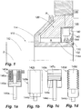
- FIG. 1 shows a first embodiment of a sealing system according to the invention. This is between a shaft 112, which forms the rotor 110 of the system together with a radial flange 114 shown in section, and a fixed housing portion 120, which forms the stator 120 in the context of the invention, application.
- the sealing ring 130 provided for this purpose is fastened to a plate 122 of the stator 120 and is therefore rotationally immovable with respect to a rotation axis 2 of the shaft 112 with respect to this plate 122.
- the sealing ring 130 extends substantially axially, with its radially inward direction side facing a sealing lip 132 is provided, which in the stationary state of FIG. 1 on an outer surface 114a of the radial flange 114 of the rotor.
- an actuator 140 Radially outside of the sealing ring 130, an actuator 140 is shown, which is representative of a plurality of identically arranged circumferentially identical actuators and has a fixedly provided on the stator actuator base 142 and a radially displaceable relative to this actuator base 142 Aktorit 144 has. This actuator pin 144 extends to an outer side of the sealing ring 130.
- the sealing ring 130 has a shape and material condition which is suitable for pressing the sealing lip 132 against a mating surface 114a on the radial flange 114 in the absence of an external application of force by the actuator pin 144.
- the sealing lip prevents in the stationary state by abutment against the mating surface 114a, that oil or an oil / air mixture from a region A, in the intended use of oil, enters a region B, which is intended to remain free of oil.
- Actuator 140 may be configured in various ways to effect a radially outward displacement of actuator pin 144 in response to this energization, or radially inward in alternative configurations.
- the Fig. 1a to 1d show possible embodiments 140a to 140d, wherein the mobility of the Aktorloches is illustrated by dashed lines.
- FIG. 1a shows an exemplary embodiment in which the actuator 140a has a solenoid comprising a coil 146a, which when energized, the actuator pin 144a surrounded by the electromagnet displaced by means of a magnetizable collar 145a, which is provided on the Aktor busy 144a.
- Fig. 1b shows an actuator 140b based on a piezoelectric effect or electrostriction whose actuator base 142b is deformable by the application of current.
- Fig. 1c shows a capacitive actuator having a capacitor plate 147c that can be electrically charged by the controller 148, thereby causing movement of an opposing backplate 145c on the actuator pin 144c.
- the actuator pin 144d can be radially displaced.
- actuators are capable of effecting a movement of the axial pin in the radial direction on the shaft to or from the shaft by current application or fluid loading.
- an additional spring may be provided to support, which causes a movement of the Aktorstattes inward or outward when eliminating the energization or pressurization.
- a plurality of actuators are provided, so that the failure of a single actuator does not affect the functioning or seriously.
- Fig. 1e illustrates an exemplary division of a total of eight actuators 140, which are distributed over the circumference.
- the displacement of the respective actuator pin 144 can press the sealing lip 132 against the shaft or pull it off the shaft 112.
- FIG. 2 show alternative, purely mechanical embodiments of a shaft sealing system according to the invention. It comprises a rotor 210 with a shaft 212 and a circumferential radial flange 214 stationary relative to the shaft 212.
- the rotor 210 is rotatably mounted about a rotation axis 2 relative to a housing and a stator 220 provided thereon.
- the shaft sealing system has a sealing ring 230, which in the case of the embodiments of FIG. 2
- instead of fixed to the rotor 220 rotatably on the rotor 210 and thus rotates together with the rotor relative to the stator 220.
- a sealing lip 232 is provided, which rests in the rest state of the shaft 210 due to the shape of the sealing ring 230 at a right angle or parallel to the rotation axis 2 aligned counter surface 220a of the stator 220.
- 230 additional mass body 250 are disposed near the sealing lip 232 in the sealing ring.
- the additional mass bodies are arranged offset radially outward relative to an outwardly facing surface opposite the sealing lip 230. They are attached to this purpose on webs 252 or integrally formed with these, which in turn are attached to an outer surface on the sealing ring 230 or embedded in these. Since the additional mass bodies 250 of the embodiments of Fig. 2 Metallic, they have a much higher density than the elastomeric material of the sealing ring. The centrifugal force effect is therefore significantly greater than it would be if the additional mass body 250 were omitted. Therefore, a significantly lower rotational speed of the shaft 210 is sufficient to separate the sealing lip 232 from the opposing surface 220a. Thus, a reduction in wear is achieved even at low speeds.
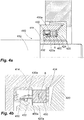
- FIGS. 3a to 3c show a further embodiment of a shaft sealing system according to the invention.
- the shaft sealing system of FIGS. 3a to 3c is provided on a shaft 312 with a radially outwardly facing and fixed to the shaft radial flange 314, which together form the rotor 310 of the system and are rotatable relative to a housing fixedly provided on the stator 320 about the rotation axis 2.
- the sealing ring 330 rotatably provided on the rotor 310 and has a sealing lip 332, which rests at standstill of the shaft 310 on a counter surface 320a of the stator.
- FIGS. 3a to 3c has a plurality of additional mass bodies 350 for improving the centrifugal force effect on the sealing ring 330.
- these additional mass bodies 350 are not in the FIG. 2a shown manner provided directly on or in the sealing ring 330, but arranged as a clearly isolated components in a defined by the radial flange 314 and the sealing ring 330 annular space. It is a much smaller number of additional mass bodies. In the present example, a total of six additional mass bodies 350 are arranged distributed over the circumference. Each of these additional mass bodies 350 combines the vast majority of its mass in a spherical body 352, from which a support rod 354 extends to a pivot joint 356.
- a force transmission member 358 is arranged between the additional mass body 350 and the sealing ring 330, which is located both on the additional mass body 350 and on the distal end of the Sealing ring 330 is hinged pivotally.
- This design results in that a pivotal displacement of the additional mass body 350 to the outside, which occurs at sufficient rotational speeds of the shaft 312 and the in Fig. 3b indicated by dashed lines, indirectly via the force transmission member 358 initiates a radially outwardly acting tensile force in the distal end of the sealing ring 330, through which the sealing lip 332 is lifted radially from the counter surface 320a.
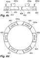
- FIGS. 4a to 4d has a high degree of relationship to the design of the FIGS. 3a to 3c on.
- a radial flange 414 co-rotating with a shaft 412 is provided, on which a sealing ring 430 is fixed with a sealing lip 432.
- the design according to the FIGS. 4a to 4d separate additional mass body 450, which are not integrated into the sealing ring 430.
- These additional mass bodies 450 are in the in Fig. 4c and 4d illustrated manner guided by link guide radially linearly movable.
- a variation, not shown, to said plug connection between the additional mass bodies 450 and the sealing ring 430 does not provide a direct or permanent connection between the additional mass body 450 and the sealing ring 430. Instead, the lifting portion 450a are arranged inside the sealing ring 430, so that a rear engagement is achieved, which ensures a radial deflection of the sealing ring 430 to the outside, as soon as the additional mass bodies are moved radially outwards due to centrifugal force.
- Fig. 5a and 5b is another principle realized to realize a non-contact seal in the rotational state and a touch-acting seal in a state of standstill.
- the arrangement of these figures comprises a shaft 512 and a radial flange 514, which together form part of a rotor 510.
- This rotor 510 is rotationally movable about the rotation axis 2 a stator 520 to which a sealing ring 530 is attached with a sealing lip 532.
- the rotor 510 has a non-elastic, preferably metallic, annular sealing body 516, which has an opposing surface 516a oriented orthogonally to the axis of rotation for the sealing ring 530.
- This sealing body 516 is pushed onto the radial flange 514 and due to a suitable clearance against this axially movable during operation.
- a rotational mobility between the sealing body 516 on the one hand and the radial flange 514 and the shaft 512 on the other hand is not given.
- the sealing body 516 has an outwardly facing groove 516b. In this groove 516b extending around a radial flange 514 fixed tangential axis 8 pivotable lever 518, at the opposite end of an additional mass body 550 is arranged.
- the sealing body 516 is displaced back to the left under the action of the O-ring 517 acting as a spring and thus comes into contact again with the sealing lip 532.
Landscapes
- Engineering & Computer Science (AREA)
- General Engineering & Computer Science (AREA)
- Mechanical Engineering (AREA)
- Sealing With Elastic Sealing Lips (AREA)
- Sealing Of Bearings (AREA)
Applications Claiming Priority (1)
| Application Number | Priority Date | Filing Date | Title |
|---|---|---|---|
| DE102011005308A DE102011005308A1 (de) | 2011-03-09 | 2011-03-09 | Wellendichtungssystem |
Publications (2)
| Publication Number | Publication Date |
|---|---|
| EP2497977A1 true EP2497977A1 (fr) | 2012-09-12 |
| EP2497977B1 EP2497977B1 (fr) | 2015-05-06 |
Family
ID=45833217
Family Applications (1)
| Application Number | Title | Priority Date | Filing Date |
|---|---|---|---|
| EP20120158900 Active EP2497977B1 (fr) | 2011-03-09 | 2012-03-09 | Dispositif de joint pour arbre |
Country Status (2)
| Country | Link |
|---|---|
| EP (1) | EP2497977B1 (fr) |
| DE (1) | DE102011005308A1 (fr) |
Cited By (7)
| Publication number | Priority date | Publication date | Assignee | Title |
|---|---|---|---|---|
| WO2015124150A1 (fr) * | 2014-02-24 | 2015-08-27 | Schaeffler Technologies AG & Co. KG | Lèvre d'étanchéité pour un élément d'étanchéité destiné à rendre étanche le joint entre deux pièces déplaçables l'une par rapport à l'autre |
| WO2017102081A1 (fr) * | 2015-12-17 | 2017-06-22 | Kaco Gmbh + Co. Kg | Joint d'étanchéité d'arbre radial et procédé permettant de rendre étanche une pièce tournante de machine au moyen d'un joint d'étanchéité d'arbre radial |
| CN110410503A (zh) * | 2018-07-13 | 2019-11-05 | 河南蒲瑞精密机械有限公司 | 一种自调弹簧压紧力的减压油封 |
| US20210116035A1 (en) * | 2018-06-28 | 2021-04-22 | Abb Schweiz Ag | Sealing arrangement for an electric machine, manufacturing method of sealing and sealing method |
| EP3862598A1 (fr) * | 2020-02-07 | 2021-08-11 | Dresser-Rand SAS | Dispositif d'étanchéité d'arbre |
| DE102021203468A1 (de) | 2021-04-08 | 2022-10-13 | Lenze Se | Wellendichtsystem |
| US11572952B2 (en) | 2021-05-29 | 2023-02-07 | Dresser-Rand SAS | Shaft sealing arrangement |
Families Citing this family (2)
| Publication number | Priority date | Publication date | Assignee | Title |
|---|---|---|---|---|
| DE102014214684B4 (de) | 2014-07-25 | 2023-03-23 | Robert Bosch Gmbh | Dichtsystem |
| DE102017216248A1 (de) * | 2017-09-14 | 2019-03-14 | Siemens Aktiengesellschaft | Adaptive kontaktlose Gasdichtung an Maschinenwellen |
Citations (8)
| Publication number | Priority date | Publication date | Assignee | Title |
|---|---|---|---|---|
| FR1003653A (fr) * | 1947-02-06 | 1952-03-20 | Dispositif d'étanchéité, en particulier pour embrayages ou accouplements hydrauliques | |
| DE7024197U (de) | 1970-06-27 | 1972-02-03 | Trw Inc | Statische Dichtung zur Verwendung in Verbindung mit einer drehbaren Welle |
| EP0246665A2 (fr) * | 1986-05-23 | 1987-11-25 | Mtu Motoren- Und Turbinen-Union MàNchen Gmbh | Joint d'étanchéité sans contact |
| DE3815655A1 (de) | 1988-05-07 | 1989-11-16 | Blohm Voss Ag | Abdichtung fuer rotierende wellen, insbesondere stevenrohrabdichtung |
| DE9201556U1 (de) * | 1992-02-08 | 1992-04-02 | FAG Kugelfischer Georg Schäfer KGaA, 8720 Schweinfurt | Lippendichtung |
| EP1122472B1 (fr) | 2000-02-01 | 2006-04-26 | Lenze Drive Systems GmbH | Etanchéité entre un arbre tournant et un logement fixe |
| DE102007007036A1 (de) | 2007-02-08 | 2008-08-21 | Carl Freudenberg Kg | Dichtungen |
| DE102007028561A1 (de) | 2007-06-19 | 2009-01-02 | Carl Freudenberg Kg | Dichtung |
Family Cites Families (1)
| Publication number | Priority date | Publication date | Assignee | Title |
|---|---|---|---|---|
| US3561770A (en) * | 1968-10-07 | 1971-02-09 | Federal Mogul Corp | Shaft seal |
-
2011
- 2011-03-09 DE DE102011005308A patent/DE102011005308A1/de not_active Withdrawn
-
2012
- 2012-03-09 EP EP20120158900 patent/EP2497977B1/fr active Active
Patent Citations (8)
| Publication number | Priority date | Publication date | Assignee | Title |
|---|---|---|---|---|
| FR1003653A (fr) * | 1947-02-06 | 1952-03-20 | Dispositif d'étanchéité, en particulier pour embrayages ou accouplements hydrauliques | |
| DE7024197U (de) | 1970-06-27 | 1972-02-03 | Trw Inc | Statische Dichtung zur Verwendung in Verbindung mit einer drehbaren Welle |
| EP0246665A2 (fr) * | 1986-05-23 | 1987-11-25 | Mtu Motoren- Und Turbinen-Union MàNchen Gmbh | Joint d'étanchéité sans contact |
| DE3815655A1 (de) | 1988-05-07 | 1989-11-16 | Blohm Voss Ag | Abdichtung fuer rotierende wellen, insbesondere stevenrohrabdichtung |
| DE9201556U1 (de) * | 1992-02-08 | 1992-04-02 | FAG Kugelfischer Georg Schäfer KGaA, 8720 Schweinfurt | Lippendichtung |
| EP1122472B1 (fr) | 2000-02-01 | 2006-04-26 | Lenze Drive Systems GmbH | Etanchéité entre un arbre tournant et un logement fixe |
| DE102007007036A1 (de) | 2007-02-08 | 2008-08-21 | Carl Freudenberg Kg | Dichtungen |
| DE102007028561A1 (de) | 2007-06-19 | 2009-01-02 | Carl Freudenberg Kg | Dichtung |
Cited By (9)
| Publication number | Priority date | Publication date | Assignee | Title |
|---|---|---|---|---|
| WO2015124150A1 (fr) * | 2014-02-24 | 2015-08-27 | Schaeffler Technologies AG & Co. KG | Lèvre d'étanchéité pour un élément d'étanchéité destiné à rendre étanche le joint entre deux pièces déplaçables l'une par rapport à l'autre |
| WO2017102081A1 (fr) * | 2015-12-17 | 2017-06-22 | Kaco Gmbh + Co. Kg | Joint d'étanchéité d'arbre radial et procédé permettant de rendre étanche une pièce tournante de machine au moyen d'un joint d'étanchéité d'arbre radial |
| US20210116035A1 (en) * | 2018-06-28 | 2021-04-22 | Abb Schweiz Ag | Sealing arrangement for an electric machine, manufacturing method of sealing and sealing method |
| US11692632B2 (en) * | 2018-06-28 | 2023-07-04 | Abb Schweiz Ag | Sealing arrangement for an electric machine, manufacturing method of sealing and sealing method |
| CN110410503A (zh) * | 2018-07-13 | 2019-11-05 | 河南蒲瑞精密机械有限公司 | 一种自调弹簧压紧力的减压油封 |
| CN110410503B (zh) * | 2018-07-13 | 2024-05-17 | 河南蒲瑞精密机械有限公司 | 一种自调弹簧压紧力的减压油封 |
| EP3862598A1 (fr) * | 2020-02-07 | 2021-08-11 | Dresser-Rand SAS | Dispositif d'étanchéité d'arbre |
| DE102021203468A1 (de) | 2021-04-08 | 2022-10-13 | Lenze Se | Wellendichtsystem |
| US11572952B2 (en) | 2021-05-29 | 2023-02-07 | Dresser-Rand SAS | Shaft sealing arrangement |
Also Published As
| Publication number | Publication date |
|---|---|
| EP2497977B1 (fr) | 2015-05-06 |
| DE102011005308A1 (de) | 2012-09-13 |
Similar Documents
| Publication | Publication Date | Title |
|---|---|---|
| EP2497977A1 (fr) | Dispositif de joint pour arbre | |
| DE3918565C2 (fr) | ||
| DE102017004436A1 (de) | Elektromechanischer Bremsenaktuator | |
| EP1170518B1 (fr) | Unité de palier verrouillable | |
| WO2018149616A1 (fr) | Actionneur pneumatique d'embrayage à réglage automatique | |
| DE2608706C2 (fr) | ||
| DE102009034401B4 (de) | Kupplungsausrücksystem | |
| DE102017008196A1 (de) | Trommelbremse mit einem elektromechanisch-hydraulischen Bremsaktuator | |
| DE19613763C1 (de) | Schaltbare, bremswirksame oder kupplungswirksame Vorrichtung, wie eine Reibungsbremse oder eine Reibungskupplung | |
| EP4034777B1 (fr) | Actionneur d'embrayage pneumatique à auto-ajustement | |
| DE4215200C2 (de) | Betätigungsvorrichtung für eine Gleitsattel-Scheibenbremse | |
| EP3814649A2 (fr) | Actionneur d'embrayage à réglage automatique | |
| DE10218112B4 (de) | Fahrzeugbremse | |
| DE2836741A1 (de) | Druckmittelbetaetigte kolbenanordnung | |
| DE102008027056A1 (de) | Reibungskupplung | |
| DE2415552A1 (de) | Federbremsbetaetigungsvorrichtung | |
| EP2093451B1 (fr) | Agencement de transmission de force de freinage | |
| EP2474754B1 (fr) | Frein à disque à auto-amplification doté d'un actionnement pneumatique ou électromécanique | |
| WO2010034501A1 (fr) | Système de joint de cardan pour un arbre de transmission | |
| EP1019642A1 (fr) | Articulation pour joints articules appropries a la transmission de couple | |
| DE10324771A1 (de) | Anordnung einer Bremsscheibe an einer Radnabe | |
| DE102006057442A1 (de) | Scheibenbremse mit elektromotorischem Aktuator in selbstverstärkender Bauart | |
| WO2021089218A1 (fr) | Embrayage à friction conique doté d'un actionneur et d'un levier pour débrayer l'embrayage | |
| DE10208641B4 (de) | Scheibenbremse mit automatischer Nachstellvorrichtung | |
| DE3311225C2 (fr) |
Legal Events
| Date | Code | Title | Description |
|---|---|---|---|
| PUAI | Public reference made under article 153(3) epc to a published international application that has entered the european phase |
Free format text: ORIGINAL CODE: 0009012 |
|
| AK | Designated contracting states |
Kind code of ref document: A1 Designated state(s): AL AT BE BG CH CY CZ DE DK EE ES FI FR GB GR HR HU IE IS IT LI LT LU LV MC MK MT NL NO PL PT RO RS SE SI SK SM TR |
|
| AX | Request for extension of the european patent |
Extension state: BA ME |
|
| 17P | Request for examination filed |
Effective date: 20130312 |
|
| 17Q | First examination report despatched |
Effective date: 20130522 |
|
| REG | Reference to a national code |
Ref country code: DE Ref legal event code: R079 Ref document number: 502012003033 Country of ref document: DE Free format text: PREVIOUS MAIN CLASS: F16J0015160000 Ipc: F16J0015000000 |
|
| GRAP | Despatch of communication of intention to grant a patent |
Free format text: ORIGINAL CODE: EPIDOSNIGR1 |
|
| RIC1 | Information provided on ipc code assigned before grant |
Ipc: F16J 15/32 20060101ALI20140924BHEP Ipc: F16J 15/16 20060101ALI20140924BHEP Ipc: F16J 15/00 20060101AFI20140924BHEP |
|
| INTG | Intention to grant announced |
Effective date: 20141027 |
|
| GRAS | Grant fee paid |
Free format text: ORIGINAL CODE: EPIDOSNIGR3 |
|
| GRAA | (expected) grant |
Free format text: ORIGINAL CODE: 0009210 |
|
| AK | Designated contracting states |
Kind code of ref document: B1 Designated state(s): AL AT BE BG CH CY CZ DE DK EE ES FI FR GB GR HR HU IE IS IT LI LT LU LV MC MK MT NL NO PL PT RO RS SE SI SK SM TR |
|
| REG | Reference to a national code |
Ref country code: GB Ref legal event code: FG4D Free format text: NOT ENGLISH |
|
| REG | Reference to a national code |
Ref country code: CH Ref legal event code: EP |
|
| REG | Reference to a national code |
Ref country code: IE Ref legal event code: FG4D Free format text: LANGUAGE OF EP DOCUMENT: GERMAN |
|
| REG | Reference to a national code |
Ref country code: AT Ref legal event code: REF Ref document number: 725942 Country of ref document: AT Kind code of ref document: T Effective date: 20150615 |
|
| REG | Reference to a national code |
Ref country code: DE Ref legal event code: R096 Ref document number: 502012003033 Country of ref document: DE Effective date: 20150618 |
|
| REG | Reference to a national code |
Ref country code: NL Ref legal event code: MP Effective date: 20150506 |
|
| REG | Reference to a national code |
Ref country code: LT Ref legal event code: MG4D |
|
| PG25 | Lapsed in a contracting state [announced via postgrant information from national office to epo] |
Ref country code: HR Free format text: LAPSE BECAUSE OF FAILURE TO SUBMIT A TRANSLATION OF THE DESCRIPTION OR TO PAY THE FEE WITHIN THE PRESCRIBED TIME-LIMIT Effective date: 20150506 Ref country code: FI Free format text: LAPSE BECAUSE OF FAILURE TO SUBMIT A TRANSLATION OF THE DESCRIPTION OR TO PAY THE FEE WITHIN THE PRESCRIBED TIME-LIMIT Effective date: 20150506 Ref country code: NO Free format text: LAPSE BECAUSE OF FAILURE TO SUBMIT A TRANSLATION OF THE DESCRIPTION OR TO PAY THE FEE WITHIN THE PRESCRIBED TIME-LIMIT Effective date: 20150806 Ref country code: PT Free format text: LAPSE BECAUSE OF FAILURE TO SUBMIT A TRANSLATION OF THE DESCRIPTION OR TO PAY THE FEE WITHIN THE PRESCRIBED TIME-LIMIT Effective date: 20150907 Ref country code: ES Free format text: LAPSE BECAUSE OF FAILURE TO SUBMIT A TRANSLATION OF THE DESCRIPTION OR TO PAY THE FEE WITHIN THE PRESCRIBED TIME-LIMIT Effective date: 20150506 Ref country code: LT Free format text: LAPSE BECAUSE OF FAILURE TO SUBMIT A TRANSLATION OF THE DESCRIPTION OR TO PAY THE FEE WITHIN THE PRESCRIBED TIME-LIMIT Effective date: 20150506 |
|
| PG25 | Lapsed in a contracting state [announced via postgrant information from national office to epo] |
Ref country code: IS Free format text: LAPSE BECAUSE OF FAILURE TO SUBMIT A TRANSLATION OF THE DESCRIPTION OR TO PAY THE FEE WITHIN THE PRESCRIBED TIME-LIMIT Effective date: 20150906 Ref country code: RS Free format text: LAPSE BECAUSE OF FAILURE TO SUBMIT A TRANSLATION OF THE DESCRIPTION OR TO PAY THE FEE WITHIN THE PRESCRIBED TIME-LIMIT Effective date: 20150506 Ref country code: GR Free format text: LAPSE BECAUSE OF FAILURE TO SUBMIT A TRANSLATION OF THE DESCRIPTION OR TO PAY THE FEE WITHIN THE PRESCRIBED TIME-LIMIT Effective date: 20150807 Ref country code: BG Free format text: LAPSE BECAUSE OF FAILURE TO SUBMIT A TRANSLATION OF THE DESCRIPTION OR TO PAY THE FEE WITHIN THE PRESCRIBED TIME-LIMIT Effective date: 20150806 Ref country code: LV Free format text: LAPSE BECAUSE OF FAILURE TO SUBMIT A TRANSLATION OF THE DESCRIPTION OR TO PAY THE FEE WITHIN THE PRESCRIBED TIME-LIMIT Effective date: 20150506 |
|
| PG25 | Lapsed in a contracting state [announced via postgrant information from national office to epo] |
Ref country code: DK Free format text: LAPSE BECAUSE OF FAILURE TO SUBMIT A TRANSLATION OF THE DESCRIPTION OR TO PAY THE FEE WITHIN THE PRESCRIBED TIME-LIMIT Effective date: 20150506 Ref country code: EE Free format text: LAPSE BECAUSE OF FAILURE TO SUBMIT A TRANSLATION OF THE DESCRIPTION OR TO PAY THE FEE WITHIN THE PRESCRIBED TIME-LIMIT Effective date: 20150506 |
|
| REG | Reference to a national code |
Ref country code: DE Ref legal event code: R097 Ref document number: 502012003033 Country of ref document: DE |
|
| PG25 | Lapsed in a contracting state [announced via postgrant information from national office to epo] |
Ref country code: PL Free format text: LAPSE BECAUSE OF FAILURE TO SUBMIT A TRANSLATION OF THE DESCRIPTION OR TO PAY THE FEE WITHIN THE PRESCRIBED TIME-LIMIT Effective date: 20150506 Ref country code: CZ Free format text: LAPSE BECAUSE OF FAILURE TO SUBMIT A TRANSLATION OF THE DESCRIPTION OR TO PAY THE FEE WITHIN THE PRESCRIBED TIME-LIMIT Effective date: 20150506 Ref country code: SK Free format text: LAPSE BECAUSE OF FAILURE TO SUBMIT A TRANSLATION OF THE DESCRIPTION OR TO PAY THE FEE WITHIN THE PRESCRIBED TIME-LIMIT Effective date: 20150506 Ref country code: RO Free format text: LAPSE BECAUSE OF NON-PAYMENT OF DUE FEES Effective date: 20150506 |
|
| PLBE | No opposition filed within time limit |
Free format text: ORIGINAL CODE: 0009261 |
|
| STAA | Information on the status of an ep patent application or granted ep patent |
Free format text: STATUS: NO OPPOSITION FILED WITHIN TIME LIMIT |
|
| 26N | No opposition filed |
Effective date: 20160209 |
|
| PG25 | Lapsed in a contracting state [announced via postgrant information from national office to epo] |
Ref country code: IT Free format text: LAPSE BECAUSE OF FAILURE TO SUBMIT A TRANSLATION OF THE DESCRIPTION OR TO PAY THE FEE WITHIN THE PRESCRIBED TIME-LIMIT Effective date: 20150506 |
|
| PG25 | Lapsed in a contracting state [announced via postgrant information from national office to epo] |
Ref country code: SI Free format text: LAPSE BECAUSE OF FAILURE TO SUBMIT A TRANSLATION OF THE DESCRIPTION OR TO PAY THE FEE WITHIN THE PRESCRIBED TIME-LIMIT Effective date: 20150506 |
|
| PG25 | Lapsed in a contracting state [announced via postgrant information from national office to epo] |
Ref country code: BE Free format text: LAPSE BECAUSE OF NON-PAYMENT OF DUE FEES Effective date: 20160331 |
|
| PG25 | Lapsed in a contracting state [announced via postgrant information from national office to epo] |
Ref country code: MC Free format text: LAPSE BECAUSE OF FAILURE TO SUBMIT A TRANSLATION OF THE DESCRIPTION OR TO PAY THE FEE WITHIN THE PRESCRIBED TIME-LIMIT Effective date: 20150506 Ref country code: LU Free format text: LAPSE BECAUSE OF FAILURE TO SUBMIT A TRANSLATION OF THE DESCRIPTION OR TO PAY THE FEE WITHIN THE PRESCRIBED TIME-LIMIT Effective date: 20160309 |
|
| REG | Reference to a national code |
Ref country code: CH Ref legal event code: PL |
|
| GBPC | Gb: european patent ceased through non-payment of renewal fee |
Effective date: 20160309 |
|
| REG | Reference to a national code |
Ref country code: IE Ref legal event code: MM4A |
|
| REG | Reference to a national code |
Ref country code: FR Ref legal event code: ST Effective date: 20161130 |
|
| PG25 | Lapsed in a contracting state [announced via postgrant information from national office to epo] |
Ref country code: GB Free format text: LAPSE BECAUSE OF NON-PAYMENT OF DUE FEES Effective date: 20160309 Ref country code: FR Free format text: LAPSE BECAUSE OF NON-PAYMENT OF DUE FEES Effective date: 20160331 Ref country code: LI Free format text: LAPSE BECAUSE OF NON-PAYMENT OF DUE FEES Effective date: 20160331 Ref country code: IE Free format text: LAPSE BECAUSE OF NON-PAYMENT OF DUE FEES Effective date: 20160309 Ref country code: CH Free format text: LAPSE BECAUSE OF NON-PAYMENT OF DUE FEES Effective date: 20160331 |
|
| PG25 | Lapsed in a contracting state [announced via postgrant information from national office to epo] |
Ref country code: SE Free format text: LAPSE BECAUSE OF FAILURE TO SUBMIT A TRANSLATION OF THE DESCRIPTION OR TO PAY THE FEE WITHIN THE PRESCRIBED TIME-LIMIT Effective date: 20150506 Ref country code: NL Free format text: LAPSE BECAUSE OF FAILURE TO SUBMIT A TRANSLATION OF THE DESCRIPTION OR TO PAY THE FEE WITHIN THE PRESCRIBED TIME-LIMIT Effective date: 20150506 |
|
| PG25 | Lapsed in a contracting state [announced via postgrant information from national office to epo] |
Ref country code: MT Free format text: LAPSE BECAUSE OF FAILURE TO SUBMIT A TRANSLATION OF THE DESCRIPTION OR TO PAY THE FEE WITHIN THE PRESCRIBED TIME-LIMIT Effective date: 20150506 |
|
| REG | Reference to a national code |
Ref country code: AT Ref legal event code: MM01 Ref document number: 725942 Country of ref document: AT Kind code of ref document: T Effective date: 20170309 |
|
| PG25 | Lapsed in a contracting state [announced via postgrant information from national office to epo] |
Ref country code: HU Free format text: LAPSE BECAUSE OF FAILURE TO SUBMIT A TRANSLATION OF THE DESCRIPTION OR TO PAY THE FEE WITHIN THE PRESCRIBED TIME-LIMIT; INVALID AB INITIO Effective date: 20120309 Ref country code: SM Free format text: LAPSE BECAUSE OF FAILURE TO SUBMIT A TRANSLATION OF THE DESCRIPTION OR TO PAY THE FEE WITHIN THE PRESCRIBED TIME-LIMIT Effective date: 20150506 Ref country code: CY Free format text: LAPSE BECAUSE OF FAILURE TO SUBMIT A TRANSLATION OF THE DESCRIPTION OR TO PAY THE FEE WITHIN THE PRESCRIBED TIME-LIMIT Effective date: 20150506 |
|
| PG25 | Lapsed in a contracting state [announced via postgrant information from national office to epo] |
Ref country code: TR Free format text: LAPSE BECAUSE OF FAILURE TO SUBMIT A TRANSLATION OF THE DESCRIPTION OR TO PAY THE FEE WITHIN THE PRESCRIBED TIME-LIMIT Effective date: 20150506 Ref country code: MK Free format text: LAPSE BECAUSE OF FAILURE TO SUBMIT A TRANSLATION OF THE DESCRIPTION OR TO PAY THE FEE WITHIN THE PRESCRIBED TIME-LIMIT Effective date: 20150506 |
|
| PG25 | Lapsed in a contracting state [announced via postgrant information from national office to epo] |
Ref country code: AT Free format text: LAPSE BECAUSE OF NON-PAYMENT OF DUE FEES Effective date: 20170309 |
|
| PG25 | Lapsed in a contracting state [announced via postgrant information from national office to epo] |
Ref country code: AL Free format text: LAPSE BECAUSE OF FAILURE TO SUBMIT A TRANSLATION OF THE DESCRIPTION OR TO PAY THE FEE WITHIN THE PRESCRIBED TIME-LIMIT Effective date: 20150506 |
|
| REG | Reference to a national code |
Ref country code: DE Ref legal event code: R081 Ref document number: 502012003033 Country of ref document: DE Owner name: UNIVERSITAET PADERBORN, DE Free format text: FORMER OWNERS: LENZE DRIVES GMBH, 32699 EXTERTAL, DE; UNIVERSITAET PADERBORN, 33098 PADERBORN, DE Ref country code: DE Ref legal event code: R081 Ref document number: 502012003033 Country of ref document: DE Owner name: LENZE SE, DE Free format text: FORMER OWNERS: LENZE DRIVES GMBH, 32699 EXTERTAL, DE; UNIVERSITAET PADERBORN, 33098 PADERBORN, DE |
|
| PGFP | Annual fee paid to national office [announced via postgrant information from national office to epo] |
Ref country code: DE Payment date: 20260320 Year of fee payment: 15 |