EP2497982A1 - Séparateur de système - Google Patents
Séparateur de système Download PDFInfo
- Publication number
- EP2497982A1 EP2497982A1 EP12157627A EP12157627A EP2497982A1 EP 2497982 A1 EP2497982 A1 EP 2497982A1 EP 12157627 A EP12157627 A EP 12157627A EP 12157627 A EP12157627 A EP 12157627A EP 2497982 A1 EP2497982 A1 EP 2497982A1
- Authority
- EP
- European Patent Office
- Prior art keywords
- securing element
- system separator
- groove
- housing
- annular
- Prior art date
- Legal status (The legal status is an assumption and is not a legal conclusion. Google has not performed a legal analysis and makes no representation as to the accuracy of the status listed.)
- Granted
Links
Images


Classifications
-
- F—MECHANICAL ENGINEERING; LIGHTING; HEATING; WEAPONS; BLASTING
- F16—ENGINEERING ELEMENTS AND UNITS; GENERAL MEASURES FOR PRODUCING AND MAINTAINING EFFECTIVE FUNCTIONING OF MACHINES OR INSTALLATIONS; THERMAL INSULATION IN GENERAL
- F16K—VALVES; TAPS; COCKS; ACTUATING-FLOATS; DEVICES FOR VENTING OR AERATING
- F16K15/00—Check valves
- F16K15/02—Check valves with guided rigid valve members
- F16K15/06—Check valves with guided rigid valve members with guided stems
- F16K15/063—Check valves with guided rigid valve members with guided stems the valve being loaded by a spring
- F16K15/066—Check valves with guided rigid valve members with guided stems the valve being loaded by a spring with a plurality of valve members
-
- F—MECHANICAL ENGINEERING; LIGHTING; HEATING; WEAPONS; BLASTING
- F16—ENGINEERING ELEMENTS AND UNITS; GENERAL MEASURES FOR PRODUCING AND MAINTAINING EFFECTIVE FUNCTIONING OF MACHINES OR INSTALLATIONS; THERMAL INSULATION IN GENERAL
- F16K—VALVES; TAPS; COCKS; ACTUATING-FLOATS; DEVICES FOR VENTING OR AERATING
- F16K27/00—Construction of housing; Use of materials therefor
- F16K27/02—Construction of housing; Use of materials therefor of lift valves
- F16K27/0209—Check valves or pivoted valves
Definitions
- the invention relates to a system separator according to the preamble of claim 1.
- a system separator is known with a housing, the housing of which defines an inlet chamber, an intermediate chamber and an outlet chamber, wherein the system separator further comprises two positioned in the housing, in the direction of flow of a medium in series, a backflow preventer, namely a first, inlet-side backflow preventer, which between the inlet chamber and the intermediate chamber is connected, and a second outlet-side non-return valve, which is connected between the intermediate chamber and the outlet chamber.
- the system separator disclosed therein comprises a bleed valve with which the intermediate chamber between the two non-return valves can be vented or discharged, wherein the bleed valve is controlled depending on a differential pressure between the pressure in the inlet chamber and the pressure in the intermediate chamber. Then, when this differential pressure drops below a defined limit, the drain valve opens to vent the intermediate chamber into the atmosphere.
- the backflow preventer known system separator each comprise a nozzle body with a valve seat, a valve plate with seal and a spring element, wherein the spring force provided by the spring element presses the valve plate of the respective backflow preventer against a valve seat provided by the respective nozzle body.
- the respective valve disk can be lifted off the valve seat of the respective nozzle body.
- the nozzle bodies of the backflow preventer installed in the housing of the system separator are secured in the housing of the system separator by screwing the nozzle bodies over a thread in the housing of the system separator.
- This screwing the nozzle body of the backflow preventer in the housing of the system separator has the disadvantage that it is cumbersome and requires large forces.
- the invention is based on the object to provide a novel system separator.
- the present invention provides a simple backup of the nozzle bodies of the backflow preventer in the housing of the system separator without the need of screwing the nozzle body to the housing ready. Therefore, lower forces are required to secure the nozzle body in the housing of the system separator.
- the inventive design of the annular, divided at a circumferential position and cross-sectional plate-like security elements not only a simple backup and installation of the nozzle body in the housing of the system separator is possible, furthermore, a sufficiently large contact area between the respective fuse element and the respective nozzle body is provided to the each nozzle body in the housing of the system separator safe to keep.
- each annular and cross-sectional plate-like securing element at each circumferential position on a greater radial extent than axial extent, each annular and cross-sectional plate-like securing element radially inside the projection of the respective nozzle body and radially outside the respective groove of the housing to the intermediate chamber towards limiting wall at least partially covered.
- This embodiment of the annular and cross-sectional plate-like securing elements allows a particularly preferred mounting of the nozzle body of the backflow preventer in the housing of the system separator.
- a further securing element designed as a retaining clip is provided in addition to the annular cross-sectional plate-like securing element.
- the additional retaining clips can be used to support the installation of the nozzle bodies of the non-return valves in the housing of the system separator.
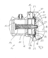
- Fig. 1 1 shows a partial cross section through individual assemblies of a system separator 10 according to the invention, namely a cross section through a housing 11 of the system separator 10 and a cross section through an inlet side non-return valve 12 accommodated in the housing 11 of the system separator 10.
- outlet-side backflow preventer recorded in the housing 11 a not shown.
- the housing 11 of the system separator 10 provides an inlet chamber 13, an intermediate chamber 14 and an outlet chamber (not shown), the backflow preventers being received in the housing 11 such that the inlet side non-return valve 12 is positioned between the inlet chamber 13 and the intermediate chamber 14, and the outlet side non-return valve, not shown, is positioned between the intermediate chamber 14 and the outlet chamber of the system separator 10, not shown.
- the inlet side non-return valve 12 is thus connected between the inlet chamber 13 and the intermediate chamber 14 of the system separator 10, whereas the outlet side non-return valve is connected between the intermediate chamber 14 and the outlet chamber of the system separator 10.
- the housing 10 is associated with a lid which can be screwed to a portion 15 of the housing 11 of the system separator 10 to close the intermediate chamber 14 of the system separator 10 on one side of the housing 11.
- a system separator 10 has an in Fig. 1 not shown drain valve, which is inserted in the assembled state in an opening 16 in the housing 11 of the system separator 10 and communicates with the intermediate chamber 14 such that when viewed in the flow direction of a medium between the two backflow preventer positioned intermediate chamber 14 can be vented via the drain valve, not shown ,
- the backflow preventer of the system separator 10 each have a nozzle body 17 through which a medium flows, a valve disk 18, a spring element 19 and a support element 20, wherein the respective nozzle body 17, the respective valve disk 18 and the respective spring element on the respective support element 20 of the respective backflow preventer Attack 19.
- Each nozzle body 17 provides a valve seat 21.
- the respective valve seat 21 cooperates with the valve disk 20 of the respective non-return valve, namely with a seal 22 received by the respective valve disk 20.
- Each nozzle body 17 of each backflow preventer comprises a projection 23 radially outward. Then, when the respective backflow preventer is mounted in the housing 11 of the system door 10, the respective radially outer protrusions 23 of the respective nozzle body 17 project into a respective groove 24 in the housing 11.
- the respective groove 24 is (see in particular Fig. 2 ) interrupted at a circumferential position or executed radially open and ring-like.
- each backflow preventer is secured in a corresponding groove 24 of the housing 11 of the system separator via at least one securing element.
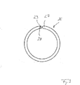
- FIG. 1 and 2 a variant of the invention in which in the region of each backflow preventer between the respective annular circumferential projection 23 of the respective nozzle body 17 and the respective groove 24 of the housing 11 of the system separator 10 to the intermediate chamber 14 towards limiting wall 25 an annular, divided at a circumferential position and in the Cross-section plate-like securing element 26 is positioned, which in Fig. 3 is shown in solo representation.
- the securing element 26 As a result of the separation or division of the securing element 26 at a circumferential position, it forms two adjoining or mutually adjacent ends 27 and 28 which can be pressed apart elastically in the axial direction and thus bent open. In the circumferential direction and thus also radial direction, the respective securing element 26 is virtually non-bendable due to its plate-like contouring, namely neither bendable nor compressible. The bending of the securing element 26 takes place in the axial direction thereof.
- the respective securing element 26 is axially alsbiegbar, namely by axially pushing apart the already mentioned, opposite ends 27 and 28th of the securing element 26, wherein after the axial disengagement of one of the ends 27 and 28 in the groove 24 can be threaded, and wherein by subsequent rotation or rotation of the securing element 26 about an axis extending in the same axial direction, the securing element 26 is fully threaded into the groove 24 can be.
- a recess 29 is formed, which serves as Einfädel Anlagen for threading the securing element 26 into the groove 24.
- a tool can be inserted to rotate the securing element 26 about the axial direction and thus threading the same completely into the groove 24.
- Each annular and in cross-section plate-like securing element 26 has at each circumferential position thereof a greater radial extent than axial extent. This provides relative to the axial direction in the circumferential direction, a relatively high rigidity of the plate-like securing element 26, so that although it is not elastically bendable in the axial direction in the circumferential direction.
- Each annular and in cross-section plate-like securing element 26 radially overlies the projection 23 of the respective nozzle body 17 and radially outside the respective groove 24 of the housing 11 to the intermediate chamber 14 towards limiting wall 25 at least in sections.
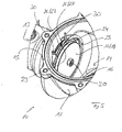
- Fig. 4 and 5 show a development of the invention, in which in addition to the already mentioned, annular and cross-sectional plate-like securing element 26 another, formed as a retaining clip securing element 30 is provided in the region of each backflow preventer, which between the respective annular and cross-sectional plate-like securing element 26 and the respective Groove 24 of the housing 11 to the intermediate chamber 14 towards limiting wall 25 is positioned.
- This formed as a retaining clip 30 further securing element is also annular and divided at a circumferential position, but designed to be circular in cross-section, so that the same axial extent of the radial extension corresponds.
- the circular cross-section securing elements 30 and retaining clips are therefore elastically bendable in the circumferential direction. To position the retaining clips in the respective groove 24 of the housing 11, they are circumferentially compressed at the opposite ends of the retaining clips 30, inserted into the groove 24 and then released.
- the invention allows a simple and safe installation of the backflow preventer, namely the nozzle body 17 of the same, in the housing 11 of the system separator 10 without the need for large assembly forces, as would be required when screwing the nozzle body in the housing according to the prior art.
Landscapes
- Engineering & Computer Science (AREA)
- General Engineering & Computer Science (AREA)
- Mechanical Engineering (AREA)
- Check Valves (AREA)
Applications Claiming Priority (1)
| Application Number | Priority Date | Filing Date | Title |
|---|---|---|---|
| DE102011013718A DE102011013718A1 (de) | 2011-03-11 | 2011-03-11 | Systemtrenner |
Publications (2)
| Publication Number | Publication Date |
|---|---|
| EP2497982A1 true EP2497982A1 (fr) | 2012-09-12 |
| EP2497982B1 EP2497982B1 (fr) | 2018-09-12 |
Family
ID=45841195
Family Applications (1)
| Application Number | Title | Priority Date | Filing Date |
|---|---|---|---|
| EP12157627.6A Active EP2497982B1 (fr) | 2011-03-11 | 2012-03-01 | Séparateur de système |
Country Status (2)
| Country | Link |
|---|---|
| EP (1) | EP2497982B1 (fr) |
| DE (1) | DE102011013718A1 (fr) |
Citations (5)
| Publication number | Priority date | Publication date | Assignee | Title |
|---|---|---|---|---|
| US3401436A (en) * | 1966-08-23 | 1968-09-17 | Int Harvester Co | Internal spring ring clip |
| US4284097A (en) * | 1978-03-28 | 1981-08-18 | Amtrol Inc. | In line back flow preventer |
| US5181535A (en) * | 1988-12-20 | 1993-01-26 | Scaramucci John P | Compact swing check valve |
| DE4204386C2 (de) | 1992-02-14 | 1994-01-20 | Honeywell Braukmann Gmbh | Systemtrenner |
| EP1350896A2 (fr) * | 2002-04-03 | 2003-10-08 | Hans Sasserath & Co Kg | Arrangement de soupapes pour un disjoncteur hydraulique |
-
2011
- 2011-03-11 DE DE102011013718A patent/DE102011013718A1/de not_active Ceased
-
2012
- 2012-03-01 EP EP12157627.6A patent/EP2497982B1/fr active Active
Patent Citations (5)
| Publication number | Priority date | Publication date | Assignee | Title |
|---|---|---|---|---|
| US3401436A (en) * | 1966-08-23 | 1968-09-17 | Int Harvester Co | Internal spring ring clip |
| US4284097A (en) * | 1978-03-28 | 1981-08-18 | Amtrol Inc. | In line back flow preventer |
| US5181535A (en) * | 1988-12-20 | 1993-01-26 | Scaramucci John P | Compact swing check valve |
| DE4204386C2 (de) | 1992-02-14 | 1994-01-20 | Honeywell Braukmann Gmbh | Systemtrenner |
| EP1350896A2 (fr) * | 2002-04-03 | 2003-10-08 | Hans Sasserath & Co Kg | Arrangement de soupapes pour un disjoncteur hydraulique |
Also Published As
| Publication number | Publication date |
|---|---|
| EP2497982B1 (fr) | 2018-09-12 |
| DE102011013718A1 (de) | 2012-09-13 |
Similar Documents
| Publication | Publication Date | Title |
|---|---|---|
| EP3268106B1 (fr) | Filtre comprenant une soupape de contournement de filtre et cartouche filtrante associée | |
| DE69513478T2 (de) | Filter und Verfahren zu dessen Herstellung | |
| EP3750612B1 (fr) | Dispositif de traitement de fluides, en particulier liquides, et élément de traitement d'un dispositif de traitement | |
| EP2252820B1 (fr) | Assemblage d'une soupape intégrée et d'un filtre tamis | |
| EP2720771B1 (fr) | Filtre à liquide comportant un conduit d'évacuation de liquide excentré | |
| EP3213803B1 (fr) | Système de filtre | |
| DE3100037C2 (fr) | ||
| EP3750611B1 (fr) | Dispositif de traitement de fluides, en particulier liquides, et élément de traitement d'un dispositif de traitement | |
| EP3431841B1 (fr) | Dispositif composant de soupape et soupape de commande doté d'un composant de soupape | |
| DE102014011786A1 (de) | Filtersystem und Filterelement mit Dichtungsvorrichtung | |
| EP1866051B1 (fr) | Systeme de filtration d'huile | |
| EP2864016B1 (fr) | Filtre à liquide pourvu d'une soupape de contournement de filtre et d'un canal d'évacuation central, et élément filtrant pour un filtre à liquide | |
| WO2008009324A1 (fr) | Ensemble filtre à huile et élément filtrant associé | |
| EP2337618B1 (fr) | Dispositif filtrant | |
| EP3458175A1 (fr) | Dispositif de filtration | |
| DE20119058U1 (de) | Rohrbruchventil | |
| EP0463289A1 (fr) | Vanne, notamment pour filtre d'huile de graissage d'un moteur à combustion | |
| DE202019101825U1 (de) | Hochdruckfilter mit Mitnehmerstrukturen | |
| EP1951398A1 (fr) | Systeme de filtration d'huile et element filtrant pour systeme de filtration d'huile | |
| EP2497982B1 (fr) | Séparateur de système | |
| EP3535039B1 (fr) | Dispositif de filtration | |
| DE102014001722B4 (de) | Filtergehäuse und Fluidfilter | |
| EP2801672B1 (fr) | Séparateur de système | |
| DE102011056758B4 (de) | Sicherheitsventil | |
| EP3544714B1 (fr) | Élément filtrant et filtre pour fluides muni d'une bague baïonnette rotative |
Legal Events
| Date | Code | Title | Description |
|---|---|---|---|
| PUAI | Public reference made under article 153(3) epc to a published international application that has entered the european phase |
Free format text: ORIGINAL CODE: 0009012 |
|
| AK | Designated contracting states |
Kind code of ref document: A1 Designated state(s): AL AT BE BG CH CY CZ DE DK EE ES FI FR GB GR HR HU IE IS IT LI LT LU LV MC MK MT NL NO PL PT RO RS SE SI SK SM TR |
|
| AX | Request for extension of the european patent |
Extension state: BA ME |
|
| 17P | Request for examination filed |
Effective date: 20130305 |
|
| STAA | Information on the status of an ep patent application or granted ep patent |
Free format text: STATUS: EXAMINATION IS IN PROGRESS |
|
| 17Q | First examination report despatched |
Effective date: 20170720 |
|
| GRAP | Despatch of communication of intention to grant a patent |
Free format text: ORIGINAL CODE: EPIDOSNIGR1 |
|
| STAA | Information on the status of an ep patent application or granted ep patent |
Free format text: STATUS: GRANT OF PATENT IS INTENDED |
|
| INTG | Intention to grant announced |
Effective date: 20180216 |
|
| GRAJ | Information related to disapproval of communication of intention to grant by the applicant or resumption of examination proceedings by the epo deleted |
Free format text: ORIGINAL CODE: EPIDOSDIGR1 |
|
| STAA | Information on the status of an ep patent application or granted ep patent |
Free format text: STATUS: EXAMINATION IS IN PROGRESS |
|
| GRAS | Grant fee paid |
Free format text: ORIGINAL CODE: EPIDOSNIGR3 |
|
| STAA | Information on the status of an ep patent application or granted ep patent |
Free format text: STATUS: GRANT OF PATENT IS INTENDED |
|
| INTC | Intention to grant announced (deleted) | ||
| GRAP | Despatch of communication of intention to grant a patent |
Free format text: ORIGINAL CODE: EPIDOSNIGR1 |
|
| GRAA | (expected) grant |
Free format text: ORIGINAL CODE: 0009210 |
|
| STAA | Information on the status of an ep patent application or granted ep patent |
Free format text: STATUS: THE PATENT HAS BEEN GRANTED |
|
| INTG | Intention to grant announced |
Effective date: 20180730 |
|
| AK | Designated contracting states |
Kind code of ref document: B1 Designated state(s): AL AT BE BG CH CY CZ DE DK EE ES FI FR GB GR HR HU IE IS IT LI LT LU LV MC MK MT NL NO PL PT RO RS SE SI SK SM TR |
|
| REG | Reference to a national code |
Ref country code: GB Ref legal event code: FG4D Free format text: NOT ENGLISH |
|
| REG | Reference to a national code |
Ref country code: CH Ref legal event code: EP |
|
| REG | Reference to a national code |
Ref country code: IE Ref legal event code: FG4D Free format text: LANGUAGE OF EP DOCUMENT: GERMAN |
|
| REG | Reference to a national code |
Ref country code: DE Ref legal event code: R096 Ref document number: 502012013406 Country of ref document: DE |
|
| REG | Reference to a national code |
Ref country code: AT Ref legal event code: REF Ref document number: 1040995 Country of ref document: AT Kind code of ref document: T Effective date: 20181015 |
|
| REG | Reference to a national code |
Ref country code: NL Ref legal event code: MP Effective date: 20180912 |
|
| REG | Reference to a national code |
Ref country code: LT Ref legal event code: MG4D |
|
| PG25 | Lapsed in a contracting state [announced via postgrant information from national office to epo] |
Ref country code: NO Free format text: LAPSE BECAUSE OF FAILURE TO SUBMIT A TRANSLATION OF THE DESCRIPTION OR TO PAY THE FEE WITHIN THE PRESCRIBED TIME-LIMIT Effective date: 20181212 Ref country code: BG Free format text: LAPSE BECAUSE OF FAILURE TO SUBMIT A TRANSLATION OF THE DESCRIPTION OR TO PAY THE FEE WITHIN THE PRESCRIBED TIME-LIMIT Effective date: 20181212 Ref country code: SE Free format text: LAPSE BECAUSE OF FAILURE TO SUBMIT A TRANSLATION OF THE DESCRIPTION OR TO PAY THE FEE WITHIN THE PRESCRIBED TIME-LIMIT Effective date: 20180912 Ref country code: GR Free format text: LAPSE BECAUSE OF FAILURE TO SUBMIT A TRANSLATION OF THE DESCRIPTION OR TO PAY THE FEE WITHIN THE PRESCRIBED TIME-LIMIT Effective date: 20181213 Ref country code: LT Free format text: LAPSE BECAUSE OF FAILURE TO SUBMIT A TRANSLATION OF THE DESCRIPTION OR TO PAY THE FEE WITHIN THE PRESCRIBED TIME-LIMIT Effective date: 20180912 Ref country code: FI Free format text: LAPSE BECAUSE OF FAILURE TO SUBMIT A TRANSLATION OF THE DESCRIPTION OR TO PAY THE FEE WITHIN THE PRESCRIBED TIME-LIMIT Effective date: 20180912 Ref country code: RS Free format text: LAPSE BECAUSE OF FAILURE TO SUBMIT A TRANSLATION OF THE DESCRIPTION OR TO PAY THE FEE WITHIN THE PRESCRIBED TIME-LIMIT Effective date: 20180912 |
|
| PG25 | Lapsed in a contracting state [announced via postgrant information from national office to epo] |
Ref country code: AL Free format text: LAPSE BECAUSE OF FAILURE TO SUBMIT A TRANSLATION OF THE DESCRIPTION OR TO PAY THE FEE WITHIN THE PRESCRIBED TIME-LIMIT Effective date: 20180912 Ref country code: LV Free format text: LAPSE BECAUSE OF FAILURE TO SUBMIT A TRANSLATION OF THE DESCRIPTION OR TO PAY THE FEE WITHIN THE PRESCRIBED TIME-LIMIT Effective date: 20180912 Ref country code: HR Free format text: LAPSE BECAUSE OF FAILURE TO SUBMIT A TRANSLATION OF THE DESCRIPTION OR TO PAY THE FEE WITHIN THE PRESCRIBED TIME-LIMIT Effective date: 20180912 |
|
| PG25 | Lapsed in a contracting state [announced via postgrant information from national office to epo] |
Ref country code: CZ Free format text: LAPSE BECAUSE OF FAILURE TO SUBMIT A TRANSLATION OF THE DESCRIPTION OR TO PAY THE FEE WITHIN THE PRESCRIBED TIME-LIMIT Effective date: 20180912 Ref country code: NL Free format text: LAPSE BECAUSE OF FAILURE TO SUBMIT A TRANSLATION OF THE DESCRIPTION OR TO PAY THE FEE WITHIN THE PRESCRIBED TIME-LIMIT Effective date: 20180912 Ref country code: IT Free format text: LAPSE BECAUSE OF FAILURE TO SUBMIT A TRANSLATION OF THE DESCRIPTION OR TO PAY THE FEE WITHIN THE PRESCRIBED TIME-LIMIT Effective date: 20180912 Ref country code: RO Free format text: LAPSE BECAUSE OF FAILURE TO SUBMIT A TRANSLATION OF THE DESCRIPTION OR TO PAY THE FEE WITHIN THE PRESCRIBED TIME-LIMIT Effective date: 20180912 Ref country code: EE Free format text: LAPSE BECAUSE OF FAILURE TO SUBMIT A TRANSLATION OF THE DESCRIPTION OR TO PAY THE FEE WITHIN THE PRESCRIBED TIME-LIMIT Effective date: 20180912 Ref country code: ES Free format text: LAPSE BECAUSE OF FAILURE TO SUBMIT A TRANSLATION OF THE DESCRIPTION OR TO PAY THE FEE WITHIN THE PRESCRIBED TIME-LIMIT Effective date: 20180912 Ref country code: PL Free format text: LAPSE BECAUSE OF FAILURE TO SUBMIT A TRANSLATION OF THE DESCRIPTION OR TO PAY THE FEE WITHIN THE PRESCRIBED TIME-LIMIT Effective date: 20180912 Ref country code: IS Free format text: LAPSE BECAUSE OF FAILURE TO SUBMIT A TRANSLATION OF THE DESCRIPTION OR TO PAY THE FEE WITHIN THE PRESCRIBED TIME-LIMIT Effective date: 20190112 |
|
| PG25 | Lapsed in a contracting state [announced via postgrant information from national office to epo] |
Ref country code: PT Free format text: LAPSE BECAUSE OF FAILURE TO SUBMIT A TRANSLATION OF THE DESCRIPTION OR TO PAY THE FEE WITHIN THE PRESCRIBED TIME-LIMIT Effective date: 20190112 Ref country code: SK Free format text: LAPSE BECAUSE OF FAILURE TO SUBMIT A TRANSLATION OF THE DESCRIPTION OR TO PAY THE FEE WITHIN THE PRESCRIBED TIME-LIMIT Effective date: 20180912 Ref country code: SM Free format text: LAPSE BECAUSE OF FAILURE TO SUBMIT A TRANSLATION OF THE DESCRIPTION OR TO PAY THE FEE WITHIN THE PRESCRIBED TIME-LIMIT Effective date: 20180912 |
|
| REG | Reference to a national code |
Ref country code: DE Ref legal event code: R097 Ref document number: 502012013406 Country of ref document: DE |
|
| PLBE | No opposition filed within time limit |
Free format text: ORIGINAL CODE: 0009261 |
|
| STAA | Information on the status of an ep patent application or granted ep patent |
Free format text: STATUS: NO OPPOSITION FILED WITHIN TIME LIMIT |
|
| PG25 | Lapsed in a contracting state [announced via postgrant information from national office to epo] |
Ref country code: DK Free format text: LAPSE BECAUSE OF FAILURE TO SUBMIT A TRANSLATION OF THE DESCRIPTION OR TO PAY THE FEE WITHIN THE PRESCRIBED TIME-LIMIT Effective date: 20180912 |
|
| 26N | No opposition filed |
Effective date: 20190613 |
|
| PG25 | Lapsed in a contracting state [announced via postgrant information from national office to epo] |
Ref country code: SI Free format text: LAPSE BECAUSE OF FAILURE TO SUBMIT A TRANSLATION OF THE DESCRIPTION OR TO PAY THE FEE WITHIN THE PRESCRIBED TIME-LIMIT Effective date: 20180912 |
|
| PG25 | Lapsed in a contracting state [announced via postgrant information from national office to epo] |
Ref country code: MC Free format text: LAPSE BECAUSE OF FAILURE TO SUBMIT A TRANSLATION OF THE DESCRIPTION OR TO PAY THE FEE WITHIN THE PRESCRIBED TIME-LIMIT Effective date: 20180912 |
|
| REG | Reference to a national code |
Ref country code: CH Ref legal event code: PL |
|
| PG25 | Lapsed in a contracting state [announced via postgrant information from national office to epo] |
Ref country code: LU Free format text: LAPSE BECAUSE OF NON-PAYMENT OF DUE FEES Effective date: 20190301 |
|
| REG | Reference to a national code |
Ref country code: BE Ref legal event code: MM Effective date: 20190331 |
|
| PG25 | Lapsed in a contracting state [announced via postgrant information from national office to epo] |
Ref country code: CH Free format text: LAPSE BECAUSE OF NON-PAYMENT OF DUE FEES Effective date: 20190331 Ref country code: LI Free format text: LAPSE BECAUSE OF NON-PAYMENT OF DUE FEES Effective date: 20190331 Ref country code: IE Free format text: LAPSE BECAUSE OF NON-PAYMENT OF DUE FEES Effective date: 20190301 |
|
| PG25 | Lapsed in a contracting state [announced via postgrant information from national office to epo] |
Ref country code: BE Free format text: LAPSE BECAUSE OF NON-PAYMENT OF DUE FEES Effective date: 20190331 |
|
| PG25 | Lapsed in a contracting state [announced via postgrant information from national office to epo] |
Ref country code: TR Free format text: LAPSE BECAUSE OF FAILURE TO SUBMIT A TRANSLATION OF THE DESCRIPTION OR TO PAY THE FEE WITHIN THE PRESCRIBED TIME-LIMIT Effective date: 20180912 |
|
| PG25 | Lapsed in a contracting state [announced via postgrant information from national office to epo] |
Ref country code: MT Free format text: LAPSE BECAUSE OF FAILURE TO SUBMIT A TRANSLATION OF THE DESCRIPTION OR TO PAY THE FEE WITHIN THE PRESCRIBED TIME-LIMIT Effective date: 20180912 |
|
| REG | Reference to a national code |
Ref country code: AT Ref legal event code: MM01 Ref document number: 1040995 Country of ref document: AT Kind code of ref document: T Effective date: 20190301 |
|
| PG25 | Lapsed in a contracting state [announced via postgrant information from national office to epo] |
Ref country code: AT Free format text: LAPSE BECAUSE OF NON-PAYMENT OF DUE FEES Effective date: 20190301 |
|
| PG25 | Lapsed in a contracting state [announced via postgrant information from national office to epo] |
Ref country code: CY Free format text: LAPSE BECAUSE OF FAILURE TO SUBMIT A TRANSLATION OF THE DESCRIPTION OR TO PAY THE FEE WITHIN THE PRESCRIBED TIME-LIMIT Effective date: 20180912 |
|
| PG25 | Lapsed in a contracting state [announced via postgrant information from national office to epo] |
Ref country code: HU Free format text: LAPSE BECAUSE OF FAILURE TO SUBMIT A TRANSLATION OF THE DESCRIPTION OR TO PAY THE FEE WITHIN THE PRESCRIBED TIME-LIMIT; INVALID AB INITIO Effective date: 20120301 |
|
| REG | Reference to a national code |
Ref country code: DE Ref legal event code: R081 Ref document number: 502012013406 Country of ref document: DE Owner name: PITTWAY SARL, CH Free format text: FORMER OWNER: HONEYWELL TECHNOLOGIES SARL, ROLLE, CH |
|
| REG | Reference to a national code |
Ref country code: GB Ref legal event code: 732E Free format text: REGISTERED BETWEEN 20220505 AND 20220512 |
|
| PG25 | Lapsed in a contracting state [announced via postgrant information from national office to epo] |
Ref country code: MK Free format text: LAPSE BECAUSE OF FAILURE TO SUBMIT A TRANSLATION OF THE DESCRIPTION OR TO PAY THE FEE WITHIN THE PRESCRIBED TIME-LIMIT Effective date: 20180912 |
|
| P01 | Opt-out of the competence of the unified patent court (upc) registered |
Effective date: 20230827 |
|
| PGFP | Annual fee paid to national office [announced via postgrant information from national office to epo] |
Ref country code: DE Payment date: 20250428 Year of fee payment: 14 |
|
| PGFP | Annual fee paid to national office [announced via postgrant information from national office to epo] |
Ref country code: GB Payment date: 20260323 Year of fee payment: 15 |
|
| PGFP | Annual fee paid to national office [announced via postgrant information from national office to epo] |
Ref country code: FR Payment date: 20260323 Year of fee payment: 15 |