EP2498007B1 - Wärmedämmvorrichtung für eine hydraulische Regelgruppe - Google Patents
Wärmedämmvorrichtung für eine hydraulische Regelgruppe Download PDFInfo
- Publication number
- EP2498007B1 EP2498007B1 EP12001333.9A EP12001333A EP2498007B1 EP 2498007 B1 EP2498007 B1 EP 2498007B1 EP 12001333 A EP12001333 A EP 12001333A EP 2498007 B1 EP2498007 B1 EP 2498007B1
- Authority
- EP
- European Patent Office
- Prior art keywords
- cover shell
- thermal insulation
- insulation device
- cover
- shell element
- Prior art date
- Legal status (The legal status is an assumption and is not a legal conclusion. Google has not performed a legal analysis and makes no representation as to the accuracy of the status listed.)
- Active
Links
Images








Classifications
-
- F—MECHANICAL ENGINEERING; LIGHTING; HEATING; WEAPONS; BLASTING
- F16—ENGINEERING ELEMENTS AND UNITS; GENERAL MEASURES FOR PRODUCING AND MAINTAINING EFFECTIVE FUNCTIONING OF MACHINES OR INSTALLATIONS; THERMAL INSULATION IN GENERAL
- F16L—PIPES; JOINTS OR FITTINGS FOR PIPES; SUPPORTS FOR PIPES, CABLES OR PROTECTIVE TUBING; MEANS FOR THERMAL INSULATION IN GENERAL
- F16L59/00—Thermal insulation in general
- F16L59/14—Arrangements for the insulation of pipes or pipe systems
- F16L59/16—Arrangements specially adapted to local requirements at flanges, junctions, valves or the like
- F16L59/161—Housings for valves, tee pieces, or the like
-
- F—MECHANICAL ENGINEERING; LIGHTING; HEATING; WEAPONS; BLASTING
- F24—HEATING; RANGES; VENTILATING
- F24D—DOMESTIC- OR SPACE-HEATING SYSTEMS, e.g. CENTRAL HEATING SYSTEMS; DOMESTIC HOT-WATER SUPPLY SYSTEMS; ELEMENTS OR COMPONENTS THEREFOR
- F24D19/00—Details
- F24D19/0097—Casings or frame structures for hydraulic components
-
- F—MECHANICAL ENGINEERING; LIGHTING; HEATING; WEAPONS; BLASTING
- F24—HEATING; RANGES; VENTILATING
- F24D—DOMESTIC- OR SPACE-HEATING SYSTEMS, e.g. CENTRAL HEATING SYSTEMS; DOMESTIC HOT-WATER SUPPLY SYSTEMS; ELEMENTS OR COMPONENTS THEREFOR
- F24D3/00—Hot-water central heating systems
- F24D3/10—Feed-line arrangements, e.g. providing for heat-accumulator tanks, expansion tanks ; Hydraulic components of a central heating system
Definitions
- the present invention relates to a thermal insulation device for a hydraulic control group with control or regulating unit and / or pump unit according to the preamble of claim 1 such as from DE 94 11864 U1 known.
- Hydraulic control groups usually comprise a pipe section of a supply line and a pipe section of a return line of a fluid-carrying piping system, fittings and in some cases a control unit and / or a pump unit.
- control groups which consist of a pipe section of a flow, a pipe section of a return and a control or regulating unit and / or a pump unit
- this is for example previously achieved by providing the complete control group with an insulating hood.
- An insulating hood has the advantage that it is easy to assemble and disassemble when, for example, a control element must be replaced. In addition, it offers protection against contact with the rule group.
- EP 0561 037 A1 describes a device for supplying a circuit of a heat or cooling system, in which openings are provided in an upper shell, to pass through the essential for the function of an assembly parts of the units and controls.
- a thermal insulation device for a hydraulic control group comprising a back shell made of a thermally insulating material, at least one cover shell element made of a heat-insulating material for insulating fluid-carrying pipe sections of the control group and a cover for covering the control group, wherein the cover has ventilation openings, wherein the Cover shell element has a recess for the control unit and / or the pump unit and wherein the control or regulating unit and / or the pump unit protrudes from the cover shell element.
- the fluid-carrying pipe sections can be specifically damped against heat losses, so that the requirements of a given energy saving regulation are met. Since the control unit and / or the pump unit, in particular the pump head, the hydraulic control group are not covered with a heat-insulating material, their overheating is avoided.
- the cover which is provided with ventilation openings, thus avoids overheating of the control or regulating unit and / or the pump unit of the hydraulic control group, provides protection against contact of the control group and can be visually appealing.
- the cover on the back shell or on the at least one cover shell element can be fastened.
- the cover can for example consist of a plastic, in particular of a thermoformable plastic or foamed polypropylene (EPP).
- the cover shell element and / or the rear shell are formed profiled for receiving components of the control group, in particular for receiving fluid-carrying pipe sections.
- the cover shell For example, depressions, elevations or recesses, which are adapted to the geometry of the components, in particular the fluid-carrying pipe sections, the control group.
- the at least one cover shell element is reversible.
- the same cover shell elements can be used in different designs of a rule group.
- the back shell has a device for fastening a regulator. This has the advantage that the cable guide of the controller is carried out via the rear shell and the cover shell element can be removed without cables are entrained with the cover shell element.
- the at least one cover shell element is integrally formed. This is advantageous for the assembly, since only one cover shell element is needed to protect fluid-carrying pipe sections against heat loss.
- the cover shell element may be C-shaped and / or have a recess for a control or regulating unit and / or the pump unit.
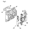
- FIG. 1 shows a control group 10 for a solar station.
- the control group 10 includes a flow 12, a return 14 and a high-pressure pump 16 arranged in the return 14. Further shows FIG. 1 a back shell 18 of a thermal insulation device and a fastener 20 for securing the back shell 18 to a wall.
- the rear shell 18 is formed profiled for a substantially accurate fit of the pipe sections of the flow 12 and the return line 14.
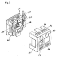
- the rear shell 18 is arranged at the rear of the control group 10 and the front of the fluid-carrying pipe sections of the flow 12 and the return 14 is covered with a cover shell element 22 of the thermal insulation device.
- the pump head of the pump 16 and temperature indicators 23 of the flow 12 and the return 14 protrude from the cover shell element 22.
- a cover 24 can be fastened to the rear shell 18 by clamping the cover shell element 22 onto the rear shell 18. She instructs their top and front ventilation slots 26 on.
- openings 27 are provided for measuring displays of the control group 10.
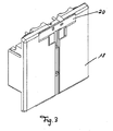
- FIG. 3 the rear side of the rear shell 18 and the fastening element 20 arranged thereon can be seen.
- the fastener 20 is attachable to a wall and has forks 28 (see FIG. 1 ), which engage in the back shell 20 to hold the back shell 20.
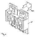
- FIG. 4 shows an alternative embodiment of a fork 128.
- the cover shell element 22 is shown.
- the cover shell member 22 is formed integrally with a substantially C-shaped basic shape and has an upper portion 22a, a middle portion 22b, and a lower portion 22c.
- the opening of the C-shaped basic shape corresponds to a recess for the pump 18.
- the cover shell element 22 is formed profiled with undercuts, depressions and projections for receiving individual elements of the control group 10.
- predetermined breaking points S1, S2, S3 are provided on the integrally formed cover shell element to disassemble the one-piece cover shell element into individual cover shell parts.
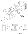
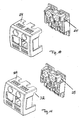
- cover shell parts separated at the predetermined breaking points S2 and S3, namely upper cover shell part 23a, middle cover shell part 23b and lower cover shell part 23b are in the FIGS. 7a, 7b . 8a, 8b and 9a, 9b shown.
- cover shell parts 23a, 23b and 23c are designed so that they can be combined individually to form a cover shell, so that they cover the fluid-carrying pipe section substantially completely.
- a set of cover shell parts 23a, 23b and 23c is sufficient to cover substantially completely the fluid-carrying pipe sections of the flow 12 or return 14 in various geometric arrangements of a control group.
- the upper deck shell portion 23a is also designed to be reversible about its transverse axis. Furthermore, the cover shell part 23a has a side surface 25 with an opening on. The side surface 25 opposite surface 29 is closed (see FIGS. 10 and 11 ).
- rule groups 10 for solar system often have a security group 31, which require an opening of the cover shell portion 23a and consequently also an opening 32 of the cover 24.
- FIG. 10 shows the use of the cover shell part for solar system control groups.
- control groups of a heating system no safety group and thus no opening of the cover shell part is necessary.
- the cover shell part 23 c can be turned so that the opening 32 in the cover 32 is covered by the cover shell part 23 c.
- the use of the cover shell part in a control group of a heating group is in Fig. 11 shown.
- the Figures 12a and 12b show the cover shell element 22 in the installed state.
- the cover shell element 22 covers the fluid-carrying pipe sections 12 and 14 of the control group 10 and the pump head of the pump 16 protrudes from the cover shell element 22.
- FIGS. 13a . 13b and 13c different uses of the cover shell parts 23a, 23b, 23c are shown, wherein for the use of the cover shell part 23c this along the in Fig. 6 shown predetermined breaking point S1 is separated.
- FIG. 14 shows the assembly of an additional regulator 34 on the rear shell 18, wherein the controller 34 is fixed to the rear shell 18.
- FIGS. 15a, 15b represent the rear shell 18, cover shell element 22 and cover 24 existing thermal insulation device in the assembled state.
- the covers 24 °.124 cover the control group and the cover shell element 22nd
- Foamed polystyrene or foamed polypropylene are suitable as materials for the cover shell element 22 and the rear shell 18.
- the cover 24, 124 may be made of a thermoformable plastic or of foamed polystyrene or foamed polypropylene.
- any rule group can be used such as a regulated or unregulated heating circuit group, a boiler loader for boilers or the like.
- an integrally formed cover shell element 122 is designed reversible.
- the FIGS. 16a and 16b each show the front side 140 and the back 142 of the cover shell element 122.
- This one-piece cover shell element 122 is suitable both for right-hand or left-hand pumping arranged in a control group.
- FIGS. 16a . 16b embodiment shown can be dismantled, and the middle and the lower deck shell part are thus reversibly gestaltbar.
Landscapes
- Engineering & Computer Science (AREA)
- General Engineering & Computer Science (AREA)
- Mechanical Engineering (AREA)
- Physics & Mathematics (AREA)
- Thermal Sciences (AREA)
- Chemical & Material Sciences (AREA)
- Combustion & Propulsion (AREA)
- Details Of Reciprocating Pumps (AREA)
- Thermal Insulation (AREA)
Description
- Die vorliegende Erfindung betrifft eine Wärmedämmvorrichtung für eine hydraulische Regelgruppe mit Steuer- oder Regeleinheit und/oder Pumpeneinheit gemäß dem Oberbegriff des Anspruchs 1 wie beispielsweise aus der
DE 94 11864 U1 bekannt. - Hydraulische Regelgruppen umfassen üblicherweise einen Rohrabschnitt eines Vorlaufs und einen Rohrabschnitt eines Rücklaufs eines fluidführenden Rohrleitungssystems, Armaturen sowie teilweise eine Steuer- oder Regeleinheit und/oder eine Pumpeneinheit.
- Aufgrund von Energieeinsparvorgaben ist es erforderlich, den Vor- und Rücklauf einer hydraulischen Regelgruppe gegen Wärmeverlust zu isolieren. Bei Regelgruppen, die aus einem Rohrabschnitt eines Vorlaufs, einen Rohrabschnitt eines Rücklaufs und einer Steuer - oder Regeleinheit und/oder einer Pumpeneinheit bestehen, wird dies beispielsweise bisher dadurch erzielt, dass die komplette Regelgruppe mit einer Isolierhaube versehen wird. Eine Isolierhaube hat den Vorteil, dass sie einfach zu montieren und demontieren ist, wenn beispielsweise ein Regelelement getauscht werden muss. Darüber hinaus bietet sie Berührungsschutz vor der Regelgruppe.
- In der
EP 0561 037 A1 wird eine Vorrichtung zur Versorgung eines Kreislaufes einer Wärme- oder Kälteversorgungsanlage beschreiben, bei der in einer Oberschale Durchbrechungen vorgesehen sind, um die für die Funktion einer Baugruppe wesentlichen Teile der Aggregate und Bedienelemente hindurchtreten zu lassen. - Bei der Verwendung von Regelelementen wie beispielsweise elektronische Regler oder Hocheffizienzpumpen besteht jedoch das Problem, dass diese im Betrieb warm oder von dem in den Rohrleitungen fließenden Fluid erwärmt werden. Aufgrund der die hydraulische Regelgruppe umgebenden Isolierhaube kann die Wärme, die in den elektronischen Geräten entsteht, nicht abgeführt werden. Dies führt dazu, dass ein elektronischer Regler bzw. eine Hocheffizienzpumpe überhitzen, fehlerhaft regeln und die Lebensdauer der Regler bzw. Hocheffizienzpumpe drastisch verkürzt ist.
- Es ist Aufgabe der vorliegenden Erfindung eine Wärmedämmvorrichtung für hydraulische Regelgruppen bereitzustellen, die eine gute Wärmedämmung der fluidführenden Rohrleitungsabschnitte einer Regelgruppe bewirkt und die Überhitzung von elektronischen Regelelementen oder einer Pumpe in der hydraulischen Regelgruppe vermeidet, wobei die Wärmedämmvorrichtung einen Schutz der Regelgruppe bietet.
- Erfindungsgemäß wird dies mit Hilfe einer Wärmedämmvorrichtung für eine hydraulische Regelgruppe gelöst umfassend eine Rückschale aus einem wärmeisolierenden Material, wenigstens ein Deckschalenelement aus einem wärmeisolierenden Material zur Isolierung von fluidführenden Rohrleitungsabschnitten der Regelgruppe und eine Abdeckhaube zum Bedecken der Regelgruppe, wobei die Abdeckhaube Belüftungsöffnungen aufweist,wobei das Deckschalenelement eine Aussparung für die Steuer- oder Regeleinheit und/oder die Pumpeneinheit aufweist und wobei die Steuer- oder Regeleinheit und/oder die Pumpeneinheit aus dem Deckschalenelement hervorragt.
- Mit Hilfe der erfindungsgemäßen Wärmedämmvorrichtung lassen sich die fluidführenden Rohrleitungsabschnitte gezielt gegen Wärmeverluste dämmen, so dass die Erfordernisse einer gegebenen Energieeinsparverordnung erfüllt werden. Da die Steuer - oder Regeleinheit und/oder die Pumpeneinheit, insbesondere der Pumpenkopf, der hydraulischen Regelgruppe nicht mit einem wärmeisolierenden Material bedeckt sind, wird deren Überhitzen vermieden.
- Die Abdeckhaube, die mit Belüftungsöffnungen versehen ist, vermeidet somit ein Überhitzen der Steuer - oder Regeleinheit und/oder der Pumpeneinheit der hydraulischen Regelgruppe, bietet einen Berührungsschutz der Regelgruppe und lässt sich optisch ansprechend gestalten.
- Für eine einfache Montage oder Demontage zu Wartungszwecken ist es von Vorteil, dass die Abdeckhaube an der Rückschale oder an dem wenigstens einen Deckschalenelement befestigbar ist. Die Abdeckhaube kann beispielsweise aus einem Kunststoff, insbesondere aus einem tiefziehbaren Kunststoff oder geschäumtem Polypropylen (EPP), bestehen.
- Für eine besonders gute Wärmedämmung ist es vorteilhaft, dass das Deckschalenelement und/oder die Rückschale für die Aufnahme von Bauteilen der Regelgruppe, insbesondere für die Aufnahme von fluidführenden Rohrleitungsabschnitten, profiliert ausgebildet sind. Hierbei kann die Deckschale beispielsweise Vertiefungen, Erhöhungen oder Aussparungen aufweisen, die an die Geometrie der Bauteile, insbesondere der fluidführenden Rohrleitungsabschnitte, der Regelgruppe angepasst sind.
- Da bei den verschiedenen Einsatzbereichen einer hydraulischen Regelgruppe Vor- und Rücklauf unterschiedlich angeordnet sein können, ebenso wie die Pumpe oder ein Regler sowohl am Vorlauf oder am Rücklauf angeordnet sein können, ist es von Vorteil, dass das wenigstens eine Deckschalenelement wendbar ist. Somit können bei verschiedenen Bauformen einer Regelgruppe die gleichen Deckschalenelemente verwendet werden.
- Bei einer bevorzugten Ausführungsform weist die Rückschale eine Vorrichtung zur Befestigung eines Reglers auf. Dies hat den Vorteil, dass die Kabelführung des Reglers über die Rückschale erfolgt und das Deckschalenelement abgenommen werden kann, ohne dass Kabel mit dem Deckschalenelement mitgeführt werden.
- Weiterhin ist bevorzugt, dass das wenigstens eine Deckschalenelement einstückig ausgebildet ist. Dies ist für die Montage von Vorteil, da nur ein Deckschalenelement benötigt wird, um fluidführende Rohrleitungsabschnitte gegen Wärmeverlust zu schützen. Beispielsweise kann das Deckschalenelement C-förmig gestaltet sein und/oder eine Aussparung für ein Steuer- oder Regeleinheit und/oder die Pumpeneinheit aufweisen.
- Vorteilhafte Ausführungsformen der Erfindung werden anhand der beigefügten Zeichnungen näher erläutert, in denen zeigen:
- Figur 1:
- eine Regelgruppe mit einer Rückschale in zerlegter Darstellung;
- Figur 2:
- eine teilweise eingebaute Wärmedämmvorrichtung mit abgenommener Abdeckhaube;
- Figur 3:
- eine Rückseite der Rückschale;
- Figur 4:
- die Rückschale mit einer alternativen Befestigungsvorrichtung;
- Figur 5:
- ein Deckschalenelement und eine Rückschale in zerlegter Darstellung;
- Figur 6:
- das Deckschalenelement der
Figur 5 in Vorderansicht; - Figur 7a, 7b:
- ein oberes Deckschalenteil;
- Figur 8a, 8b:
- ein mittleres Deckschalenteil;
- Figur 9a, 9b:
- ein unteres Deckschalenteil;
- Figur. 10:
- die Verwendung des oberen Deckschalenteils in einer Regelgruppe einer Solaranlage;
- Figur. 11:
- die Verwendung des oberen Deckschalenteils in einer Regelgruppe einer Heizanlage;
- Figur 12a, 12b:
- das in den
Figuren 5 und6 dargestellte Deckschalenelement in eingebautem Zustand mit abgenommener Abdeckhaube; - Figur 13a, 13b, 13c:
- Deckschalenteile in eingebautem Zustand;
- Figur 14:
- eine Rückschale mit einem Regler;
- Figur 15a, 15b:
- zwei Ausführungsformen einer Abdeckhaube im montiertem Zustand; und
- Figur 16a, 16b:
- ein wendbares Deckschalenelement.
-
Figur 1 zeigt eine Regelgruppe 10 für eine Solarstation. Die Regelgruppe 10 umfasst einen Vorlauf 12, einen Rücklauf 14 und eine im Rücklauf 14 angeordnete Hochleistungspumpe 16. Weiterhin zeigtFigur 1 eine Rückschale 18 einer Wärmedämmvorrichtung und ein Befestigungsmittel 20 zum Befestigen der Rückschale 18 an einer Wand. - Die Rückschale 18 ist für eine im Wesentlichen passgenaue Aufnahme der Rohrleitungsabschnitte des Vorlaufs 12 und des Rücklauf 14 profiliert ausgebildet.
- In
Figur 2 ist die Rückschale 18 an der Rückseite der Regelgruppe 10 angeordnet und die Vorderseite der fluidführenden Rohrleitungsabschnitte des Vorlaufs 12 und des Rücklaufs 14 ist mit einem Deckschalenelement 22 der Wärmedämmvorrichtung bedeckt. Der Pumpenkopf der Pumpe 16 sowie Temperaturanzeigen 23 des Vorlaufs 12 und des Rücklaufs 14 ragen aus dem Deckschalenelement 22 hervor. Weiterhin ist inFigur 2 eine Abdeckhaube 24 zu erkennen. Die Abdeckhaube 24 ist an der Rückschale 18 befestigbar, indem das Deckschalenelement 22 auf die Rückschale 18 geklemmt wird. Sie weist an ihrer Oberseite und an der Vorderseite Belüftungsschlitze 26 auf. Weiterhin sind Öffnungen 27 für Messanzeigen der Regelgruppe 10 vorgesehen. - In
Figur 3 ist die Rückseite der Rückschale 18 und das daran angeordnete Befestigungselement 20 erkennbar. Das Befestigungselement 20 ist an einer Wand befestigbar und weist Gabeln 28 (sieheFigur 1 ) auf, die in die Rückschale 20 eingreifen, um die Rückschale 20 zu halten.Figur 4 zeigt eine alternative Ausführungsform einer Gabel 128. - In den
Fig. 5 und6 ist das Deckschalenelement 22 dargestellt. Das Deckschalenelement 22 ist einstückig mit im Wesentlichen C-förmiger Grundform ausgebildet und weist einen oberen Abschnitt 22a, einen mittleren Abschnitt 22b und einen unteren Abschnitt 22c auf. Die Öffnung der C-fömigen Grundform entspricht einer Aussparung für die Pumpe 18. Weiterhin ist das Deckschalenelement 22 profiliert mit Hinterschneidungen, Vertiefungen und Vorsprüngen zur Aufnahme von Einzelelementen der Regelgruppe 10 ausgebildet. - Wie insbesondere in
Fig. 6 zu erkennen ist, sind an dem einstückig ausgebildeten Deckschalenelement 22 Sollbruchstellen S1, S2, S3 vorgesehen, um das einstückige Deckschalenelement in einzelne Deckschalenteile zu zerlegen. - Die an den Sollbruchstellen S2 und S3 getrennten Deckschalenteile, nämlich oberes Deckschalenteil 23a, mittleres Deckschalenteil 23b und unteres Deckschalenteil 23b sind in den
Figuren 7a, 7b ,8a, 8b und9a, 9b dargestellt. - Da bei verschiedenen Regelgruppen der Vor- und Rücklauf vertauscht und eine Regel- oder Steuereinheit oder eine Pumpe 16 am Vorlauf oder Rücklauf angeordnet sein kann, sind die Deckschalenteile 23a, 23b und 23c so gestaltet, dass sie einzeln zu einer Deckschale kombinierbar sind, so dass sie die fluidführenden Rohrleitungsabschnitt im Wesentlichen vollständig bedecken. Somit reicht ein Satz an Deckschalenteilen 23a, 23b und 23c aus, um bei verschiedenen geometrischen Anordnungen einer Regelgruppe die fluidführenden Rohrleitungsabschnitte des Vorlaufs 12 oder Rücklaufs 14 im Wesentlichen vollständig abzudecken.
- Das obere Deckschalenteil 23a ist darüber hinaus um seine Querachse wendbar gestaltet. Weiterhin weist das Deckschalenteil 23a eine Seitenfläche 25 mit einer Öffnung auf. Die der Seitenfläche 25 gegenüberliegende Fläche 29 ist geschlossen ausgebildet (siehe
Figuren 10 und 11 ). - Wie in
Figur 1 zu erkennen ist, weisen Regelgruppen 10 für Solaranlage häufig eine Sicherheitsgruppe 31 auf, die eine Öffnung des Deckschalenteils 23a und folglich auch eine Öffnung 32 der Abdeckhaube 24 benötigen.Figur 10 zeigt die Verwendung des Deckschalenteils für Regelgruppen von Solaranlagen. Bei Regelgruppen einer Heizanlage ist keine Sicherheitsgruppe und somit auch keine Öffnung des Deckschalenteils notwendig. Um auch für Regelgruppen einer Heizgruppe eine gute Wärmeisolierung zu erhalten, kann das Deckschalenteil 23c gewendet werden, so dass die Öffnung 32 in der Abdeckhaube 32 durch das Deckschalenteil 23c bedeckt ist. Die Verwendung des Deckschalenteils in einer Regelgruppe einer Heizgruppe ist inFig. 11 gezeigt. - Die
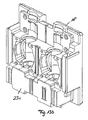
Figuren 12a und 12b zeigen das Deckschalenelement 22 im eingebauten Zustand. Das Deckschalenelement 22 bedeckt die fluidführenden Rohrleitungsabschnitte 12 und 14 der Regelgruppe 10 und der Pumpenkopf der Pumpe 16 ragt aus dem Deckschalenelement 22 hervor. - In den
Figuren 13a ,13b und13c sind verschiedene Einsatzmöglichkeiten der Deckschalenteile 23a, 23b, 23c gezeigt, wobei für den Einsatz des Deckschalenteils 23c dieses entlang der inFig. 6 dargestellten Sollbruchstelle S1 getrennt ist. -
Figur 14 zeigt die Montage eines zusätzlichen Reglers 34 auf der Rückschale 18, wobei der Regler 34 an der Rückschale 18 befestigt ist. -
Figur 15a, 15b stellen die aus Rückschale 18, Deckschalenelement 22 und Abdeckhaube 24 bestehende Wärmedämmvorrichtung im montierten Zustand dar. Die Abdeckhauben 24 bzw.124 bedecken die Regelgruppe und das Deckschalenelement 22. - Für das Deckschalenelement 22 und die Rückschale 18 eignen sich als Materialen beispielsweise geschäumtes Polystyrol oder geschäumtes Polypropylen. Die Abdeckhaube 24, 124 kann aus einem tiefziehbaren Kunststoff oder auch aus geschäumtes Polystyrol oder geschäumtes Polypropylen hergestellt werden.
- Wenn die Wärmedämmvorrichtung im Zusammenhang mit einer Regelgruppe für Solaranlagen beschrieben wurden, so kann jede beliebige Regelgruppe verwendet werden wie beispielsweise eine geregelte oder ungeregelte Heizkreisgruppe, eine Kesselladegruppe für Festwertkessel oder dergleichen.
- Bei einer in den
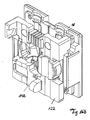
Figuren 16a und16b dargestellten Ausführungsform ist ein einstückig ausgebildetes Deckschalenelement 122 wendbar gestaltet. DieFiguren 16a und16b zeigen jeweils die Vorderseite 140 bzw. die Rückseite 142 des Deckschalenelements 122. Dieses einstückige Deckschalenelement 122 ist sowohl für rechtsseitig oder linksseitig angeordnete Pumpen in einer Regelgruppe geeignet. - Da die in den
Figuren 16a ,16b dargestellte Ausführungsform zerlegbar ist, sind auch das mittlere und das untere Deckschalenteil somit wendbar gestaltbar.
Claims (10)
- Wärmedämmvorrichtung für eine hydraulische Regelgruppe mit einer Steuer- oder Regeleinheit und/oder einer Pumpeneinheit umfassend eine Rückschale (18) aus einem wärmeisolierenden Material, und wenigstens ein Deckschalenelement (22; 23a, 23b, 23c; 122) aus einem wärmeisolierenden Material zur Isolierung von fluidführenden Rohrleitungsabschnitten (12, 14) der Regelgruppe (10) dadurch gekennzeichnet, dass die Wärmedämmvorrichtung eine Abdeckhaube (24; 124) zum Bedecken der Regelgruppe (10) aufweist, wobei die Abdeckhaube (24; 124) Belüftungsöffnungen (26) aufweist, und das Deckschalenelement (22; 122) eine Aussparung für die Steuer- oder Regeleinheit und/oder die Pumpeneinheit aufweist und dass die Steuer- oder Regeleinheit und/oder die Pumpeneinheit aus dem Deckschalenelement (22; 122) hervorragbar ist.
- Wärmedämmvorrichtung nach Anspruch 1, dadurch gekennzeichnet, dass die Abdeckhaube (24; 124) an der Rückschale (18) oder an dem wenigstens einen Deckschalenelement (22; 23a, 23b, 23c; 122) befestigbar ist.
- Wärmedämmvorrichtung nach einem der vorhergehenden Ansprüche, dadurch gekennzeichnet, dass die Abdeckhaube (24; 124) aus einem Kunststoff ist.
- Wärmedämmvorrichtung nach einem der vorhergehenden Ansprüche, dadurch gekennzeichnet, dass das wenigstens eine Deckschalenelement (22; 23a, 23b, 23c; 122) für die Aufnahme von Bauteilen der Regelgruppe, insbesondere für die Aufnahme von fluidführenden Rohrleitungsabschnitten (12, 14), profiliert ausgebildet ist.
- Wärmedämmvorrichtung nach einem der vorhergehenden Ansprüche, dadurch gekennzeichnet, dass die Rückschale (18) für die Aufnahme von Bauteilen der Regelgruppe, insbesondere für die Aufnahme von fluidführenden Rohrleitungsabschnitten (12, 14), profiliert ausgebildet ist.
- Wärmedämmvorrichtung nach einem der vorhergehenden Ansprüche, dadurch gekennzeichnet, dass das wenigstens eine Deckenschalenelement (23a; 122) wendbar ist.
- Wärmedämmvorrichtung nach einem der vorhergehenden Ansprüche, dadurch gekennzeichnet, dass die Rückschale (18) eine Vorrichtung zur Befestigung eines Reglers (30) aufweist.
- Wärmedämmvorrichtung nach einem der vorhergehenden Ansprüche, dadurch gekennzeichnet, dass das Deckschalenelement (22; 122) einstückig ausgebildet ist.
- Wärmedämmvorrichtung nach Anspruch 8, dadurch gekennzeichnet, dass das Deckschalenelement (22; 122) im Wesentlichen eine C-förmige Grundform aufweist.
- Wärmedämmvorrichtung nach Anspruch 8 oder 9, dadurch gekennzeichnet, dass das Deckschalenelement (22; 122) eine Aussparung für ein Regelelement, insbesondere für eine Pumpe (16), aufweist.
Applications Claiming Priority (1)
| Application Number | Priority Date | Filing Date | Title |
|---|---|---|---|
| DE202011003874U DE202011003874U1 (de) | 2011-03-11 | 2011-03-11 | Wärmedämmvorrichtung für eine hydraulische Regelgruppe |
Publications (2)
| Publication Number | Publication Date |
|---|---|
| EP2498007A1 EP2498007A1 (de) | 2012-09-12 |
| EP2498007B1 true EP2498007B1 (de) | 2016-11-16 |
Family
ID=44650385
Family Applications (1)
| Application Number | Title | Priority Date | Filing Date |
|---|---|---|---|
| EP12001333.9A Active EP2498007B1 (de) | 2011-03-11 | 2012-02-29 | Wärmedämmvorrichtung für eine hydraulische Regelgruppe |
Country Status (3)
| Country | Link |
|---|---|
| EP (1) | EP2498007B1 (de) |
| DE (1) | DE202011003874U1 (de) |
| ES (1) | ES2616209T3 (de) |
Families Citing this family (6)
| Publication number | Priority date | Publication date | Assignee | Title |
|---|---|---|---|---|
| DE202013002350U1 (de) * | 2013-03-11 | 2014-06-12 | Gebr. Tuxhorn Gmbh & Co. Kg | Isolierung für eine Armaturengruppe |
| DE202014002655U1 (de) * | 2014-03-27 | 2015-06-30 | Stiebel Eltron Gmbh & Co. Kg | Wärmeenergiesystem mit einem Wärmeerzeuger und einem Behälter |
| DE202014002654U1 (de) * | 2014-03-27 | 2015-06-30 | Stiebel Eltron Gmbh & Co. Kg | Haustechnikgerät mit einem Abschluss für einen Energiewandler |
| DE202015004260U1 (de) * | 2015-06-16 | 2016-09-19 | Gebr. Kemper Gmbh + Co. Kg Metallwerke | Modul zur Wassererwärmung |
| DE102016111444A1 (de) | 2016-06-22 | 2017-12-28 | Brugg Rohr Ag Holding | Ein zur Isolierung einer Leitung bestimmter Hüllkörper mit zwei Schalen aus expandiertem Kunststoff |
| DE202019001248U1 (de) * | 2019-03-15 | 2020-06-19 | Gebr. Kemper Gmbh + Co. Kg | Vorrichtung zur Druckentlastung eines Wassersystems und Anschlussmodul mit einer solchen Vorrichtung |
Family Cites Families (7)
| Publication number | Priority date | Publication date | Assignee | Title |
|---|---|---|---|---|
| US3556158A (en) * | 1967-04-26 | 1971-01-19 | Marvin Schneider | Insulator for pipe accouterments and the like |
| US4449554A (en) * | 1982-03-22 | 1984-05-22 | Busse Richard O | Universal removable insulation |
| DK0561037T3 (da) * | 1992-03-19 | 1996-03-11 | Dumser Metallbau Gmbh | Indretning til forsyning af et kredsløb til et varme- eller kuldeforsyningsanlæg |
| DE9411684U1 (de) * | 1994-07-19 | 1994-09-15 | Elco Klöckner Heiztechnik GmbH, 72379 Hechingen | Steuervorrichtung für einen Wärme- oder Kältekreislauf |
| DE102005014869B4 (de) * | 2005-03-30 | 2014-08-07 | F.W. Oventrop Gmbh & Co. Kg | Anordnung von Reglern in der Wärmedämmung von Armaturenbaugruppen |
| PL2306098T3 (pl) * | 2009-09-30 | 2014-03-31 | Oventrop Gmbh & Co Kg | Zespół do instalacji termoizolacyjnej odcinków przewodów rurowych ze zintegrowanym osprzętem |
| DE202010012172U1 (de) * | 2010-09-03 | 2010-12-02 | Leuschke, Reinhardt | Anordnung zur vollständigen Wärmedämmung von Rohrleitungsabschnitten einschließlich der dazugehörigen Armaturen/Armaturenbaugruppen |
-
2011
- 2011-03-11 DE DE202011003874U patent/DE202011003874U1/de not_active Expired - Lifetime
-
2012
- 2012-02-29 EP EP12001333.9A patent/EP2498007B1/de active Active
- 2012-02-29 ES ES12001333.9T patent/ES2616209T3/es active Active
Also Published As
| Publication number | Publication date |
|---|---|
| ES2616209T3 (es) | 2017-06-09 |
| EP2498007A1 (de) | 2012-09-12 |
| DE202011003874U1 (de) | 2011-08-17 |
Similar Documents
| Publication | Publication Date | Title |
|---|---|---|
| EP2498007B1 (de) | Wärmedämmvorrichtung für eine hydraulische Regelgruppe | |
| EP2154436B1 (de) | Verfahren und Vorrichtung zur Wärmenutzung | |
| DE19912821C2 (de) | Ventilanordnung | |
| DE60102417T2 (de) | Strahlplatte mit hoher Effizienz für Temperaturregulierung eines Raumes | |
| EP1170553B1 (de) | Kühldecke | |
| DE3622139A1 (de) | Wasserversorgungsanlage | |
| EP2498008B1 (de) | Gebäude | |
| DE102006053200A1 (de) | Heiz- oder Kühlanlage | |
| DE29504520U1 (de) | Heizvorrichtung mit einer Verkleidung sowie Verkleidung für eine Heizvorrichtung | |
| EP2336668A2 (de) | Wassererwärmer mit wärmeisolierendem Halter | |
| EP3106765B1 (de) | Modul zur wassererwärmung | |
| EP0950865B1 (de) | Heizvorrichtung | |
| DE19909780A1 (de) | Armaturenmodul für ein Heizungs- und/oder Warmwasserleitungssystem eines Gebäudes | |
| EP2306098B1 (de) | Anordnung zur wärmedämmenden Installation von Rohrleitungsabschnitten mit integrierten Armaturen | |
| EP2087221A1 (de) | Wärmetauscher, insbesondere für ein kraftfahrzeug | |
| EP1600839A2 (de) | Durchflussmengenregler | |
| DE19830307C2 (de) | Heizkörperventil für Heizungsanlagen | |
| DE19709534A1 (de) | Von Fluid als Wärmeträger durchströmbarer Heizkörper | |
| DE202005021994U1 (de) | Fernwärmekompaktstation mit einem multifunktionalen Sandwichrahmen | |
| DE20105092U1 (de) | Anschlusseinrichtung für einen Heizkörper sowie Winkelstück hierfür | |
| DE102010028986A1 (de) | Waschtischarmatur mit Sicherheitstemperaturbegrenzer | |
| DE10208008B4 (de) | Heizkanal | |
| DE20021612U1 (de) | Fußbodenheizung | |
| DE20016918U1 (de) | Elektrischer Durchlauferhitzer | |
| DE9013367U1 (de) | Isolierung |
Legal Events
| Date | Code | Title | Description |
|---|---|---|---|
| PUAI | Public reference made under article 153(3) epc to a published international application that has entered the european phase |
Free format text: ORIGINAL CODE: 0009012 |
|
| AK | Designated contracting states |
Kind code of ref document: A1 Designated state(s): AL AT BE BG CH CY CZ DE DK EE ES FI FR GB GR HR HU IE IS IT LI LT LU LV MC MK MT NL NO PL PT RO RS SE SI SK SM TR |
|
| AX | Request for extension of the european patent |
Extension state: BA ME |
|
| 17P | Request for examination filed |
Effective date: 20121016 |
|
| 17Q | First examination report despatched |
Effective date: 20150717 |
|
| GRAP | Despatch of communication of intention to grant a patent |
Free format text: ORIGINAL CODE: EPIDOSNIGR1 |
|
| INTG | Intention to grant announced |
Effective date: 20160607 |
|
| GRAS | Grant fee paid |
Free format text: ORIGINAL CODE: EPIDOSNIGR3 |
|
| GRAA | (expected) grant |
Free format text: ORIGINAL CODE: 0009210 |
|
| AK | Designated contracting states |
Kind code of ref document: B1 Designated state(s): AL AT BE BG CH CY CZ DE DK EE ES FI FR GB GR HR HU IE IS IT LI LT LU LV MC MK MT NL NO PL PT RO RS SE SI SK SM TR |
|
| REG | Reference to a national code |
Ref country code: GB Ref legal event code: FG4D Free format text: NOT ENGLISH |
|
| REG | Reference to a national code |
Ref country code: CH Ref legal event code: EP |
|
| REG | Reference to a national code |
Ref country code: IE Ref legal event code: FG4D Free format text: LANGUAGE OF EP DOCUMENT: GERMAN |
|
| REG | Reference to a national code |
Ref country code: AT Ref legal event code: REF Ref document number: 846303 Country of ref document: AT Kind code of ref document: T Effective date: 20161215 |
|
| REG | Reference to a national code |
Ref country code: DE Ref legal event code: R096 Ref document number: 502012008770 Country of ref document: DE |
|
| REG | Reference to a national code |
Ref country code: CH Ref legal event code: NV Representative=s name: PATENTANWAELTE SCHAAD, BALASS, MENZL AND PARTN, CH |
|
| REG | Reference to a national code |
Ref country code: FR Ref legal event code: PLFP Year of fee payment: 6 |
|
| REG | Reference to a national code |
Ref country code: NL Ref legal event code: FP |
|
| PG25 | Lapsed in a contracting state [announced via postgrant information from national office to epo] |
Ref country code: LV Free format text: LAPSE BECAUSE OF FAILURE TO SUBMIT A TRANSLATION OF THE DESCRIPTION OR TO PAY THE FEE WITHIN THE PRESCRIBED TIME-LIMIT Effective date: 20161116 |
|
| REG | Reference to a national code |
Ref country code: SE Ref legal event code: TRGR |
|
| REG | Reference to a national code |
Ref country code: LT Ref legal event code: MG4D Ref country code: NO Ref legal event code: T2 Effective date: 20161116 |
|
| PG25 | Lapsed in a contracting state [announced via postgrant information from national office to epo] |
Ref country code: GR Free format text: LAPSE BECAUSE OF FAILURE TO SUBMIT A TRANSLATION OF THE DESCRIPTION OR TO PAY THE FEE WITHIN THE PRESCRIBED TIME-LIMIT Effective date: 20170217 Ref country code: LT Free format text: LAPSE BECAUSE OF FAILURE TO SUBMIT A TRANSLATION OF THE DESCRIPTION OR TO PAY THE FEE WITHIN THE PRESCRIBED TIME-LIMIT Effective date: 20161116 |
|
| PG25 | Lapsed in a contracting state [announced via postgrant information from national office to epo] |
Ref country code: RS Free format text: LAPSE BECAUSE OF FAILURE TO SUBMIT A TRANSLATION OF THE DESCRIPTION OR TO PAY THE FEE WITHIN THE PRESCRIBED TIME-LIMIT Effective date: 20161116 Ref country code: PT Free format text: LAPSE BECAUSE OF FAILURE TO SUBMIT A TRANSLATION OF THE DESCRIPTION OR TO PAY THE FEE WITHIN THE PRESCRIBED TIME-LIMIT Effective date: 20170316 Ref country code: HR Free format text: LAPSE BECAUSE OF FAILURE TO SUBMIT A TRANSLATION OF THE DESCRIPTION OR TO PAY THE FEE WITHIN THE PRESCRIBED TIME-LIMIT Effective date: 20161116 Ref country code: FI Free format text: LAPSE BECAUSE OF FAILURE TO SUBMIT A TRANSLATION OF THE DESCRIPTION OR TO PAY THE FEE WITHIN THE PRESCRIBED TIME-LIMIT Effective date: 20161116 Ref country code: PL Free format text: LAPSE BECAUSE OF FAILURE TO SUBMIT A TRANSLATION OF THE DESCRIPTION OR TO PAY THE FEE WITHIN THE PRESCRIBED TIME-LIMIT Effective date: 20161116 |
|
| REG | Reference to a national code |
Ref country code: ES Ref legal event code: FG2A Ref document number: 2616209 Country of ref document: ES Kind code of ref document: T3 Effective date: 20170609 |
|
| PG25 | Lapsed in a contracting state [announced via postgrant information from national office to epo] |
Ref country code: SK Free format text: LAPSE BECAUSE OF FAILURE TO SUBMIT A TRANSLATION OF THE DESCRIPTION OR TO PAY THE FEE WITHIN THE PRESCRIBED TIME-LIMIT Effective date: 20161116 Ref country code: RO Free format text: LAPSE BECAUSE OF FAILURE TO SUBMIT A TRANSLATION OF THE DESCRIPTION OR TO PAY THE FEE WITHIN THE PRESCRIBED TIME-LIMIT Effective date: 20161116 Ref country code: EE Free format text: LAPSE BECAUSE OF FAILURE TO SUBMIT A TRANSLATION OF THE DESCRIPTION OR TO PAY THE FEE WITHIN THE PRESCRIBED TIME-LIMIT Effective date: 20161116 Ref country code: CZ Free format text: LAPSE BECAUSE OF FAILURE TO SUBMIT A TRANSLATION OF THE DESCRIPTION OR TO PAY THE FEE WITHIN THE PRESCRIBED TIME-LIMIT Effective date: 20161116 Ref country code: DK Free format text: LAPSE BECAUSE OF FAILURE TO SUBMIT A TRANSLATION OF THE DESCRIPTION OR TO PAY THE FEE WITHIN THE PRESCRIBED TIME-LIMIT Effective date: 20161116 |
|
| REG | Reference to a national code |
Ref country code: DE Ref legal event code: R097 Ref document number: 502012008770 Country of ref document: DE |
|
| PG25 | Lapsed in a contracting state [announced via postgrant information from national office to epo] |
Ref country code: BG Free format text: LAPSE BECAUSE OF FAILURE TO SUBMIT A TRANSLATION OF THE DESCRIPTION OR TO PAY THE FEE WITHIN THE PRESCRIBED TIME-LIMIT Effective date: 20170216 Ref country code: SM Free format text: LAPSE BECAUSE OF FAILURE TO SUBMIT A TRANSLATION OF THE DESCRIPTION OR TO PAY THE FEE WITHIN THE PRESCRIBED TIME-LIMIT Effective date: 20161116 |
|
| PLBE | No opposition filed within time limit |
Free format text: ORIGINAL CODE: 0009261 |
|
| STAA | Information on the status of an ep patent application or granted ep patent |
Free format text: STATUS: NO OPPOSITION FILED WITHIN TIME LIMIT |
|
| PG25 | Lapsed in a contracting state [announced via postgrant information from national office to epo] |
Ref country code: MC Free format text: LAPSE BECAUSE OF FAILURE TO SUBMIT A TRANSLATION OF THE DESCRIPTION OR TO PAY THE FEE WITHIN THE PRESCRIBED TIME-LIMIT Effective date: 20161116 |
|
| 26N | No opposition filed |
Effective date: 20170817 |
|
| REG | Reference to a national code |
Ref country code: IE Ref legal event code: MM4A |
|
| PG25 | Lapsed in a contracting state [announced via postgrant information from national office to epo] |
Ref country code: SI Free format text: LAPSE BECAUSE OF FAILURE TO SUBMIT A TRANSLATION OF THE DESCRIPTION OR TO PAY THE FEE WITHIN THE PRESCRIBED TIME-LIMIT Effective date: 20161116 |
|
| PG25 | Lapsed in a contracting state [announced via postgrant information from national office to epo] |
Ref country code: LU Free format text: LAPSE BECAUSE OF NON-PAYMENT OF DUE FEES Effective date: 20170228 |
|
| REG | Reference to a national code |
Ref country code: FR Ref legal event code: PLFP Year of fee payment: 7 |
|
| PG25 | Lapsed in a contracting state [announced via postgrant information from national office to epo] |
Ref country code: IE Free format text: LAPSE BECAUSE OF NON-PAYMENT OF DUE FEES Effective date: 20170228 |
|
| PG25 | Lapsed in a contracting state [announced via postgrant information from national office to epo] |
Ref country code: MT Free format text: LAPSE BECAUSE OF FAILURE TO SUBMIT A TRANSLATION OF THE DESCRIPTION OR TO PAY THE FEE WITHIN THE PRESCRIBED TIME-LIMIT Effective date: 20161116 |
|
| PG25 | Lapsed in a contracting state [announced via postgrant information from national office to epo] |
Ref country code: HU Free format text: LAPSE BECAUSE OF FAILURE TO SUBMIT A TRANSLATION OF THE DESCRIPTION OR TO PAY THE FEE WITHIN THE PRESCRIBED TIME-LIMIT; INVALID AB INITIO Effective date: 20120229 |
|
| PG25 | Lapsed in a contracting state [announced via postgrant information from national office to epo] |
Ref country code: CY Free format text: LAPSE BECAUSE OF NON-PAYMENT OF DUE FEES Effective date: 20161116 |
|
| PG25 | Lapsed in a contracting state [announced via postgrant information from national office to epo] |
Ref country code: MK Free format text: LAPSE BECAUSE OF FAILURE TO SUBMIT A TRANSLATION OF THE DESCRIPTION OR TO PAY THE FEE WITHIN THE PRESCRIBED TIME-LIMIT Effective date: 20161116 |
|
| PG25 | Lapsed in a contracting state [announced via postgrant information from national office to epo] |
Ref country code: TR Free format text: LAPSE BECAUSE OF FAILURE TO SUBMIT A TRANSLATION OF THE DESCRIPTION OR TO PAY THE FEE WITHIN THE PRESCRIBED TIME-LIMIT Effective date: 20161116 |
|
| PG25 | Lapsed in a contracting state [announced via postgrant information from national office to epo] |
Ref country code: AL Free format text: LAPSE BECAUSE OF FAILURE TO SUBMIT A TRANSLATION OF THE DESCRIPTION OR TO PAY THE FEE WITHIN THE PRESCRIBED TIME-LIMIT Effective date: 20161116 Ref country code: IS Free format text: LAPSE BECAUSE OF FAILURE TO SUBMIT A TRANSLATION OF THE DESCRIPTION OR TO PAY THE FEE WITHIN THE PRESCRIBED TIME-LIMIT Effective date: 20170316 |
|
| PGFP | Annual fee paid to national office [announced via postgrant information from national office to epo] |
Ref country code: NL Payment date: 20230226 Year of fee payment: 12 |
|
| PGFP | Annual fee paid to national office [announced via postgrant information from national office to epo] |
Ref country code: NO Payment date: 20230227 Year of fee payment: 12 Ref country code: ES Payment date: 20230301 Year of fee payment: 12 |
|
| PGFP | Annual fee paid to national office [announced via postgrant information from national office to epo] |
Ref country code: SE Payment date: 20230227 Year of fee payment: 12 |
|
| REG | Reference to a national code |
Ref country code: NL Ref legal event code: MM Effective date: 20240301 |
|
| REG | Reference to a national code |
Ref country code: SE Ref legal event code: EUG |
|
| PG25 | Lapsed in a contracting state [announced via postgrant information from national office to epo] |
Ref country code: NO Free format text: LAPSE BECAUSE OF NON-PAYMENT OF DUE FEES Effective date: 20240229 |
|
| PG25 | Lapsed in a contracting state [announced via postgrant information from national office to epo] |
Ref country code: NL Free format text: LAPSE BECAUSE OF NON-PAYMENT OF DUE FEES Effective date: 20240301 |
|
| PG25 | Lapsed in a contracting state [announced via postgrant information from national office to epo] |
Ref country code: NL Free format text: LAPSE BECAUSE OF NON-PAYMENT OF DUE FEES Effective date: 20240301 |
|
| REG | Reference to a national code |
Ref country code: ES Ref legal event code: FD2A Effective date: 20250402 |
|
| PG25 | Lapsed in a contracting state [announced via postgrant information from national office to epo] |
Ref country code: ES Free format text: LAPSE BECAUSE OF NON-PAYMENT OF DUE FEES Effective date: 20240301 |
|
| PGFP | Annual fee paid to national office [announced via postgrant information from national office to epo] |
Ref country code: BE Payment date: 20250227 Year of fee payment: 14 Ref country code: AT Payment date: 20250203 Year of fee payment: 14 Ref country code: CH Payment date: 20250304 Year of fee payment: 14 |
|
| PG25 | Lapsed in a contracting state [announced via postgrant information from national office to epo] |
Ref country code: SE Free format text: LAPSE BECAUSE OF NON-PAYMENT OF DUE FEES Effective date: 20240301 |
|
| PGFP | Annual fee paid to national office [announced via postgrant information from national office to epo] |
Ref country code: GB Payment date: 20260227 Year of fee payment: 15 |
|
| PGFP | Annual fee paid to national office [announced via postgrant information from national office to epo] |
Ref country code: DE Payment date: 20260227 Year of fee payment: 15 |
|
| PGFP | Annual fee paid to national office [announced via postgrant information from national office to epo] |
Ref country code: IT Payment date: 20260219 Year of fee payment: 15 |
|
| PGFP | Annual fee paid to national office [announced via postgrant information from national office to epo] |
Ref country code: FR Payment date: 20260225 Year of fee payment: 15 |