EP2498009A2 - Pressure vessel - Google Patents
Pressure vessel Download PDFInfo
- Publication number
- EP2498009A2 EP2498009A2 EP20120158866 EP12158866A EP2498009A2 EP 2498009 A2 EP2498009 A2 EP 2498009A2 EP 20120158866 EP20120158866 EP 20120158866 EP 12158866 A EP12158866 A EP 12158866A EP 2498009 A2 EP2498009 A2 EP 2498009A2
- Authority
- EP
- European Patent Office
- Prior art keywords
- housing
- segment
- flange segments
- diaphragm
- water
- Prior art date
- Legal status (The legal status is an assumption and is not a legal conclusion. Google has not performed a legal analysis and makes no representation as to the accuracy of the status listed.)
- Withdrawn
Links
- XLYOFNOQVPJJNP-UHFFFAOYSA-N water Substances O XLYOFNOQVPJJNP-UHFFFAOYSA-N 0.000 claims abstract description 76
- 239000012530 fluid Substances 0.000 claims description 2
- CURLTUGMZLYLDI-UHFFFAOYSA-N Carbon dioxide Chemical compound O=C=O CURLTUGMZLYLDI-UHFFFAOYSA-N 0.000 description 2
- 235000012206 bottled water Nutrition 0.000 description 2
- 239000003651 drinking water Substances 0.000 description 2
- 238000007789 sealing Methods 0.000 description 2
- 229910002092 carbon dioxide Inorganic materials 0.000 description 1
- 239000001569 carbon dioxide Substances 0.000 description 1
- 230000009977 dual effect Effects 0.000 description 1
- 239000013505 freshwater Substances 0.000 description 1
- 230000004048 modification Effects 0.000 description 1
- 238000012986 modification Methods 0.000 description 1
- 238000001223 reverse osmosis Methods 0.000 description 1
- 239000007787 solid Substances 0.000 description 1
- 230000000087 stabilizing effect Effects 0.000 description 1
- 230000008022 sublimation Effects 0.000 description 1
- 238000000859 sublimation Methods 0.000 description 1
Images


Classifications
-
- F—MECHANICAL ENGINEERING; LIGHTING; HEATING; WEAPONS; BLASTING
- F24—HEATING; RANGES; VENTILATING
- F24D—DOMESTIC- OR SPACE-HEATING SYSTEMS, e.g. CENTRAL HEATING SYSTEMS; DOMESTIC HOT-WATER SUPPLY SYSTEMS; ELEMENTS OR COMPONENTS THEREFOR
- F24D3/00—Hot-water central heating systems
- F24D3/10—Feed-line arrangements, e.g. providing for heat-accumulator tanks, expansion tanks ; Hydraulic components of a central heating system
- F24D3/1008—Feed-line arrangements, e.g. providing for heat-accumulator tanks, expansion tanks ; Hydraulic components of a central heating system expansion tanks
- F24D3/1041—Flow-through
-
- F—MECHANICAL ENGINEERING; LIGHTING; HEATING; WEAPONS; BLASTING
- F15—FLUID-PRESSURE ACTUATORS; HYDRAULICS OR PNEUMATICS IN GENERAL
- F15B—SYSTEMS ACTING BY MEANS OF FLUIDS IN GENERAL; FLUID-PRESSURE ACTUATORS, e.g. SERVOMOTORS; DETAILS OF FLUID-PRESSURE SYSTEMS, NOT OTHERWISE PROVIDED FOR
- F15B1/00—Installations or systems with accumulators; Supply reservoir or sump assemblies
- F15B1/02—Installations or systems with accumulators
- F15B1/04—Accumulators
- F15B1/08—Accumulators using a gas cushion; Gas charging devices; Indicators or floats therefor
- F15B1/10—Accumulators using a gas cushion; Gas charging devices; Indicators or floats therefor with flexible separating means
- F15B1/16—Accumulators using a gas cushion; Gas charging devices; Indicators or floats therefor with flexible separating means in the form of a tube
-
- F—MECHANICAL ENGINEERING; LIGHTING; HEATING; WEAPONS; BLASTING
- F15—FLUID-PRESSURE ACTUATORS; HYDRAULICS OR PNEUMATICS IN GENERAL
- F15B—SYSTEMS ACTING BY MEANS OF FLUIDS IN GENERAL; FLUID-PRESSURE ACTUATORS, e.g. SERVOMOTORS; DETAILS OF FLUID-PRESSURE SYSTEMS, NOT OTHERWISE PROVIDED FOR
- F15B1/00—Installations or systems with accumulators; Supply reservoir or sump assemblies
- F15B1/02—Installations or systems with accumulators
- F15B1/04—Accumulators
- F15B1/08—Accumulators using a gas cushion; Gas charging devices; Indicators or floats therefor
- F15B1/10—Accumulators using a gas cushion; Gas charging devices; Indicators or floats therefor with flexible separating means
- F15B1/106—Accumulators using a gas cushion; Gas charging devices; Indicators or floats therefor with flexible separating means characterised by the way housing components are assembled
-
- F—MECHANICAL ENGINEERING; LIGHTING; HEATING; WEAPONS; BLASTING
- F15—FLUID-PRESSURE ACTUATORS; HYDRAULICS OR PNEUMATICS IN GENERAL
- F15B—SYSTEMS ACTING BY MEANS OF FLUIDS IN GENERAL; FLUID-PRESSURE ACTUATORS, e.g. SERVOMOTORS; DETAILS OF FLUID-PRESSURE SYSTEMS, NOT OTHERWISE PROVIDED FOR
- F15B2201/00—Accumulators
- F15B2201/20—Accumulator cushioning means
- F15B2201/205—Accumulator cushioning means using gas
-
- F—MECHANICAL ENGINEERING; LIGHTING; HEATING; WEAPONS; BLASTING
- F15—FLUID-PRESSURE ACTUATORS; HYDRAULICS OR PNEUMATICS IN GENERAL
- F15B—SYSTEMS ACTING BY MEANS OF FLUIDS IN GENERAL; FLUID-PRESSURE ACTUATORS, e.g. SERVOMOTORS; DETAILS OF FLUID-PRESSURE SYSTEMS, NOT OTHERWISE PROVIDED FOR
- F15B2201/00—Accumulators
- F15B2201/30—Accumulator separating means
- F15B2201/315—Accumulator separating means having flexible separating means
- F15B2201/3151—Accumulator separating means having flexible separating means the flexible separating means being diaphragms or membranes
-
- F—MECHANICAL ENGINEERING; LIGHTING; HEATING; WEAPONS; BLASTING
- F15—FLUID-PRESSURE ACTUATORS; HYDRAULICS OR PNEUMATICS IN GENERAL
- F15B—SYSTEMS ACTING BY MEANS OF FLUIDS IN GENERAL; FLUID-PRESSURE ACTUATORS, e.g. SERVOMOTORS; DETAILS OF FLUID-PRESSURE SYSTEMS, NOT OTHERWISE PROVIDED FOR
- F15B2201/00—Accumulators
- F15B2201/30—Accumulator separating means
- F15B2201/315—Accumulator separating means having flexible separating means
- F15B2201/3156—Accumulator separating means having flexible separating means characterised by their attachment
-
- F—MECHANICAL ENGINEERING; LIGHTING; HEATING; WEAPONS; BLASTING
- F15—FLUID-PRESSURE ACTUATORS; HYDRAULICS OR PNEUMATICS IN GENERAL
- F15B—SYSTEMS ACTING BY MEANS OF FLUIDS IN GENERAL; FLUID-PRESSURE ACTUATORS, e.g. SERVOMOTORS; DETAILS OF FLUID-PRESSURE SYSTEMS, NOT OTHERWISE PROVIDED FOR
- F15B2201/00—Accumulators
- F15B2201/30—Accumulator separating means
- F15B2201/315—Accumulator separating means having flexible separating means
- F15B2201/3158—Guides for the flexible separating means, e.g. for a collapsed bladder
-
- F—MECHANICAL ENGINEERING; LIGHTING; HEATING; WEAPONS; BLASTING
- F15—FLUID-PRESSURE ACTUATORS; HYDRAULICS OR PNEUMATICS IN GENERAL
- F15B—SYSTEMS ACTING BY MEANS OF FLUIDS IN GENERAL; FLUID-PRESSURE ACTUATORS, e.g. SERVOMOTORS; DETAILS OF FLUID-PRESSURE SYSTEMS, NOT OTHERWISE PROVIDED FOR
- F15B2201/00—Accumulators
- F15B2201/40—Constructional details of accumulators not otherwise provided for
- F15B2201/405—Housings
- F15B2201/4056—Housings characterised by the attachment of housing components
Definitions
- the invention relates to a pressure vessel, more particularly to an in-line pressure vessel.
- hydro-pneumatic pressure vessels are widely employed in industrial and residential piping systems.
- hydro-pneumatic pressure vessels are used in stabilizing water pressure and absorbing water hammer in hydraulic piping systems, controlling thermal expansion in closed-loop hot water systems, and storing water in reverse osmosis systems.
- U.S. Patent No. 7,363,944 discloses such a conventional hydro-pneumatic pressure vessel, which includes a vessel unit and a rubber diaphragm disposed in the vessel unit for dividing an inner space of the vessel unit into a water chamber and an air chamber.
- a water fitting and an air valve are disposed on the vessel unit and configured for communicating fluidly and respectively with the water chamber and the air chamber. Since the conventional hydro-pneumatic pressure vessel only has one water fitting for inlet and outlet of water, it is not suitable for use in an in-line piping system. Moreover, the conventional hydro-pneumatic pressure vessel lacks a fresh circulation of water when used for storing potable water.
- a conventional in-line pressure vessel disclosed in U.S. Patent No. 6, 418, 969 which may be used to provide fresh circulation of water, includes: a tubular container; an water inlet fitting and a water outlet fitting secured respectively to opposite ends of the tubular container; a tubular diaphragm disposed in the tubular container and having opposite end portions that are connected respectively to the water inlet and water outlet fittings; and an inner pipe disposed in the diaphragm and having opposite end parts that are connected respectively to the water inlet and water outlet fittings.
- the conventional in-line pressure vessel is relatively complex in structure and costly to make.
- the object of the present invention is to provide an in-line pressure vessel that has a relatively simple structure and that is easy to assemble.
- a pressure vessel of the present invention includes:
- the preferred embodiment of a pressure vessel includes a housing unit 10, an elastic diaphragm unit 20, a pair of water fitting units 30, a pair of securing units 15, an air valve 40 and a restricting pipe 50.
- the housing unit 10 has a housing segment 12 that surrounds an axis (L), that has axially-opposite end portions, and that is comprised of first and second housing portions 121, 122 that are welded together.
- a housing segment 12 that surrounds an axis (L), that has axially-opposite end portions, and that is comprised of first and second housing portions 121, 122 that are welded together.
- Each of the end portions of the housing segment 12 has a neck section 14.
- the housing unit 10 further has a pair of housing-flange segments 13 that extend respectively from the neck sections 14 of the end portions of the housing segment 12 in a radially outward direction with respect to the axis (L).
- the diaphragm unit 20 is preferably made of rubber, and has a substantially barrel-shaped diaphragm segment 22 that is substantially disposed in the housing segment 12, that has axially-opposite end portions corresponding respectively in position to the end portions of the housing segment 12, that defines a water chamber 21 therein, and that cooperates with the housing segment 12 to define an air chamber 11 therebetween.
- Each of the end portions of the diaphragm segment 22 has a neck section 24.
- the diaphragm unit 20 further has a pair of diaphragm-flange segments 23 that extend respectively from the neck sections 24 of the end portions of the diaphragm segment 22 in the radially outward direction such that each of the housing-flange segments 13 is substantially interposed between the housing segment 12 and an adjacent one of the diaphragm-flange segments 23.
- the water fitting units 30 are disposed corresponding to the diaphragm-flange segments 23, respectively.
- Each of the water fitting units 30 has a fitting-flange segment 31 that cooperates with an adjacent one of the housing-flange segments 13 to clamp air-tightly an adjacent one of the diaphragm-flange segments 23 therebetween, and is formed with a water port 35 for fluidly communicating the water chamber 21 with an external environment.
- the pressure vessel may be configured such that one of the water fitting units 30 serves as a water inlet, and the other of the water fitting units 30 serves as a water outlet.
- Each of the fitting-flange segments 31 has a supporting portion 32 extending toward the water chamber 21, and cooperating with the neck section 14 of the adjacent one of the end portions of the housing segment 12 to clamp air-tightly the neck section 24 of the adjacent one of the end portions of the diaphragm segment 22 therebetween.
- Each of the fitting-flange segments 31 further has an extending portion 33 that extends from the supporting portion 32 into the water chamber 21, and a shoulder portion 34 that interconnects the supporting portion 32 and the extending portion 33.
- the restricting pipe 50 is disposed in the water chamber 21, fluidly communicates the water ports 35 of the water fitting units 30 to each other, and is formed with a plurality of holes 51 for fluid communication through the holes 51.
- the restricting pipe 50 has opposite end segments sleeved fittingly onto the extending portions 33 and abutting against the shoulder portions 34 of the fitting-flange segments 31, respectively.
- the neck sections 24 of the diaphragm segment 22 are respectively clamped between the neck sections 14 of the housing segment 12 and the supporting portions 32, the neck sections 24 are compressed, i.e., thicknesses of the neck sections 24 are reduced, thereby sealing off air flow between the neck sections 24 of the diaphragm segment 22 and the neck sections 14 of the housing segment 12, and water flow between the neck sections 24 and the supporting portions 32.
- Each of the housing-flange segments 13 has a distal end distal from the housing segment 12 and extending beyond the adjacent one of the diaphragm-flange segments 23 and the adjacent one of the fitting-flange segments 31 in the radially outward direction with respect to the axis (L).
- Each of the securing units 15 has: a first segment 151 extending from the distal end of the respective one of the housing-flange segments 13 in a direction along the axis (L) and away from the housing segment 12, and having a distal end distal from the distal end of the respective one of the housing-flange segments 13; and a second segment 152 extending from the distal end of the first segment 151 in a radially inward direction with respect to the axis (L), and cooperating with the respective one of the housing-flange segments 13 to clamp the respective one of the diaphragm-flange segments 23 therebetween.
- each of the securing units 15 is integrally connected to the respective one of the housing-flange segments 13, and each of the first and second segments 151, 152 thereof surrounds the axis (L).
- the securing units 15 secure the fitting-flange segments 31 to the housing-flange segments 13, respectively.
- each of the securing units 15 is implemented as having an opened state (depicted by broken line), where the second segment 152 is configured to be parallel to the corresponding first segment 151 so as to enable assembly and disassembly of the corresponding water fitting unit 30 to and from the housing unit 10 and the diaphragm unit 20, and a closed state (depicted by solid line), where the second segment 152 is configured to be perpendicular to the corresponding first segment 151 so as to secure the corresponding water fitting unit 30 to the housing unit 10 and the diaphragm unit 20.
- the air valve 40 is disposed on the second housing segment 122 and disposed corresponding to the air chamber 11, and communicates fluidly the air chamber 11 with the external environment.
- the diaphragm segment 22 When the water chamber 21 is empty (see Fig. 1 ), the diaphragm segment 22 is not expanded. When water is introduced into the water chamber 21 via the water port 35 of one of the water fitting units 30, the diaphragm segment 22 of the diaphragm unit 20 is expanded for storing water (see Fig. 3 ).
- each of the securing units 15 may be configured to include a bolt and a nut for securing the corresponding housing-flange segment 13 to the corresponding fitting-flange segment 31.
- the pressure vessel of the present invention has the following advantages.
Landscapes
- Engineering & Computer Science (AREA)
- Physics & Mathematics (AREA)
- Mechanical Engineering (AREA)
- General Engineering & Computer Science (AREA)
- Fluid Mechanics (AREA)
- Thermal Sciences (AREA)
- Chemical & Material Sciences (AREA)
- Combustion & Propulsion (AREA)
- Pressure Vessels And Lids Thereof (AREA)
- Measuring Fluid Pressure (AREA)
- Filling Or Discharging Of Gas Storage Vessels (AREA)
Abstract
Description
- The invention relates to a pressure vessel, more particularly to an in-line pressure vessel.
- Currently, hydro-pneumatic pressure vessels are widely employed in industrial and residential piping systems. For example, hydro-pneumatic pressure vessels are used in stabilizing water pressure and absorbing water hammer in hydraulic piping systems, controlling thermal expansion in closed-loop hot water systems, and storing water in reverse osmosis systems.
-
U.S. Patent No. 7,363,944 discloses such a conventional hydro-pneumatic pressure vessel, which includes a vessel unit and a rubber diaphragm disposed in the vessel unit for dividing an inner space of the vessel unit into a water chamber and an air chamber. A water fitting and an air valve are disposed on the vessel unit and configured for communicating fluidly and respectively with the water chamber and the air chamber. Since the conventional hydro-pneumatic pressure vessel only has one water fitting for inlet and outlet of water, it is not suitable for use in an in-line piping system. Moreover, the conventional hydro-pneumatic pressure vessel lacks a fresh circulation of water when used for storing potable water. - A conventional in-line pressure vessel disclosed in
U.S. Patent No. 6, 418, 969 , which may be used to provide fresh circulation of water, includes: a tubular container; an water inlet fitting and a water outlet fitting secured respectively to opposite ends of the tubular container; a tubular diaphragm disposed in the tubular container and having opposite end portions that are connected respectively to the water inlet and water outlet fittings; and an inner pipe disposed in the diaphragm and having opposite end parts that are connected respectively to the water inlet and water outlet fittings. However, since the diaphragm is shorter in length than the tubular container and must be secured tightly to the water inlet and water outlet fittings to prevent leakage of water, and since the tubular container and the water inlet and water outlet fittings must be in an airproof connection with the tubular container to prevent leakage of air, the conventional in-line pressure vessel is relatively complex in structure and costly to make. - Another conventional pressure vessel disclosed in
U.S. Patent No. 7,108,015 is similar in structure and hence in drawback to the abovementioned in-line pressure vessel disclosed inU.S. patent No. 6,418,969 . - Therefore, the object of the present invention is to provide an in-line pressure vessel that has a relatively simple structure and that is easy to assemble.
- Accordingly, a pressure vessel of the present invention includes:
- a housing unit having
- a housing segment that surrounds an axis, and that has axially-opposite end portions, and
- a pair of housing-flange segments that extend respectively from the end portions of the housing segment in a radially outward direction with respect to the axis;
- an elastic diaphragm unit having
- a substantially barrel-shaped diaphragm segment that is substantially disposed in the housing segment, that has axially-opposite end portions corresponding respectively in position to the end portions of the housing segment, that defines a water chamber therein, and that cooperates with the housing segment to define an air chamber therebetween, and
- a pair of diaphragm-flange segments that extend respectively from the end portions of the diaphragm segment in the radially outward direction such that each of the housing-flange segments is substantially interposed between the housing segment and an adjacent one of the diaphragm-flange segments; and
- a pair of water fitting units that are respectively disposed corresponding to the diaphragm-flange segments, each of the water fitting units having a fitting-flange segment that cooperates with an adjacent one of the housing-flange segments to clamp an adjacent one of the diaphragm-flange segments therebetween, and being formed with a water port for fluidly communicating the water chamber with an external environment.
- Other features and advantages of the present invention will become apparent in the following detailed description of the preferred embodiment with reference to the accompanying drawings, of which:
-
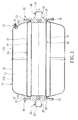
Fig. 1 is a partly sectional view of a preferred embodiment of a pressure vessel according to the invention, illustrating an empty water chamber; -
Fig. 2 is an enlarged fragmentary sectional view of the preferred embodiment; and -
Fig. 3 is another partly sectional view of the preferred embodiment, illustrating the water chamber filled with water. - As shown in
Figures 1 and2 , the preferred embodiment of a pressure vessel according to the present invention includes ahousing unit 10, anelastic diaphragm unit 20, a pair ofwater fitting units 30, a pair of securingunits 15, anair valve 40 and a restrictingpipe 50. - The
housing unit 10 has ahousing segment 12 that surrounds an axis (L), that has axially-opposite end portions, and that is comprised of first andsecond housing portions housing segment 12 is not limited to such. Each of the end portions of thehousing segment 12 has aneck section 14. Thehousing unit 10 further has a pair of housing-flange segments 13 that extend respectively from theneck sections 14 of the end portions of thehousing segment 12 in a radially outward direction with respect to the axis (L). - The
diaphragm unit 20 is preferably made of rubber, and has a substantially barrel-shaped diaphragm segment 22 that is substantially disposed in thehousing segment 12, that has axially-opposite end portions corresponding respectively in position to the end portions of thehousing segment 12, that defines awater chamber 21 therein, and that cooperates with thehousing segment 12 to define anair chamber 11 therebetween. Each of the end portions of thediaphragm segment 22 has aneck section 24. - The
diaphragm unit 20 further has a pair of diaphragm-flange segments 23 that extend respectively from theneck sections 24 of the end portions of thediaphragm segment 22 in the radially outward direction such that each of the housing-flange segments 13 is substantially interposed between thehousing segment 12 and an adjacent one of the diaphragm-flange segments 23. - The
water fitting units 30 are disposed corresponding to the diaphragm-flange segments 23, respectively. Each of thewater fitting units 30 has a fitting-flange segment 31 that cooperates with an adjacent one of the housing-flange segments 13 to clamp air-tightly an adjacent one of the diaphragm-flange segments 23 therebetween, and is formed with awater port 35 for fluidly communicating thewater chamber 21 with an external environment. In application, the pressure vessel may be configured such that one of thewater fitting units 30 serves as a water inlet, and the other of thewater fitting units 30 serves as a water outlet. - Each of the fitting-
flange segments 31 has a supportingportion 32 extending toward thewater chamber 21, and cooperating with theneck section 14 of the adjacent one of the end portions of thehousing segment 12 to clamp air-tightly theneck section 24 of the adjacent one of the end portions of thediaphragm segment 22 therebetween. Each of the fitting-flange segments 31 further has an extendingportion 33 that extends from the supportingportion 32 into thewater chamber 21, and ashoulder portion 34 that interconnects the supportingportion 32 and the extendingportion 33. The restrictingpipe 50 is disposed in thewater chamber 21, fluidly communicates thewater ports 35 of thewater fitting units 30 to each other, and is formed with a plurality ofholes 51 for fluid communication through theholes 51. The restrictingpipe 50 has opposite end segments sleeved fittingly onto the extendingportions 33 and abutting against theshoulder portions 34 of the fitting-flange segments 31, respectively. - Preferably, when the
neck sections 24 of thediaphragm segment 22 are respectively clamped between theneck sections 14 of thehousing segment 12 and the supportingportions 32, theneck sections 24 are compressed, i.e., thicknesses of theneck sections 24 are reduced, thereby sealing off air flow between theneck sections 24 of thediaphragm segment 22 and theneck sections 14 of thehousing segment 12, and water flow between theneck sections 24 and the supportingportions 32. - Each of the housing-
flange segments 13 has a distal end distal from thehousing segment 12 and extending beyond the adjacent one of the diaphragm-flange segments 23 and the adjacent one of the fitting-flange segments 31 in the radially outward direction with respect to the axis (L). Each of thesecuring units 15 has: afirst segment 151 extending from the distal end of the respective one of the housing-flange segments 13 in a direction along the axis (L) and away from thehousing segment 12, and having a distal end distal from the distal end of the respective one of the housing-flange segments 13; and asecond segment 152 extending from the distal end of thefirst segment 151 in a radially inward direction with respect to the axis (L), and cooperating with the respective one of the housing-flange segments 13 to clamp the respective one of the diaphragm-flange segments 23 therebetween. In this embodiment, each of thesecuring units 15 is integrally connected to the respective one of the housing-flange segments 13, and each of the first andsecond segments securing units 15 secure the fitting-flange segments 31 to the housing-flange segments 13, respectively. - As illustrated in
Fig. 2 , in this embodiment, each of thesecuring units 15 is implemented as having an opened state (depicted by broken line), where thesecond segment 152 is configured to be parallel to the correspondingfirst segment 151 so as to enable assembly and disassembly of the correspondingwater fitting unit 30 to and from thehousing unit 10 and thediaphragm unit 20, and a closed state (depicted by solid line), where thesecond segment 152 is configured to be perpendicular to the correspondingfirst segment 151 so as to secure the correspondingwater fitting unit 30 to thehousing unit 10 and thediaphragm unit 20. - The
air valve 40 is disposed on thesecond housing segment 122 and disposed corresponding to theair chamber 11, and communicates fluidly theair chamber 11 with the external environment. - When the
water chamber 21 is empty (seeFig. 1 ), thediaphragm segment 22 is not expanded. When water is introduced into thewater chamber 21 via thewater port 35 of one of thewater fitting units 30, thediaphragm segment 22 of thediaphragm unit 20 is expanded for storing water (seeFig. 3 ). - It should be noted that the
air valve 40 may be omitted in a modification in which inflation of theair chamber 11 is achieved through sublimation of solid carbon dioxide in theair chamber 11. Moreover, each of thesecuring units 15 may be configured to include a bolt and a nut for securing the corresponding housing-flange segment 13 to the corresponding fitting-flange segment 31. - In summary, the pressure vessel of the present invention has the following advantages.
- 1. By virtue of the dual
water fitting units 30, the pressure vessel may be configured for use in an in-line piping system. In the use of storing potable water, such a pressure vessel provides a relatively fresh water circulation. - 2. The
diaphragm unit 20 is clamped tightly between thehousing unit 10 and thewater fitting units 30 so the connection among theabovementioned units - 3. Specifically, the firm, air-tight sealing between the
neck sections 24 of thediaphragm segment 22 and theneck sections 14 of thehousing segment 12 prevents air leakage of theair chamber 11 therethrough, and that between theneck sections 24 and the supportingportions 32 prevents water leakage of thewater chamber 21 therethrough. - 4. When water is discharged from the
water chamber 21, the restrictingpipe 50 prevents over-contraction of thediaphragm segment 22 and stabilizes water flow through thewater fitting units 30. - 5. The pressure vessel of this invention has a relatively simple structure and is easy to assemble and disassemble.
Claims (10)
- A pressure vessel comprising:a housing unit (10) having
a housing segment (12) that surrounds an axis (L), and that has axially-opposite end portions, and
a pair of housing-flange segments (13) that extend respectively from said end portions of said housing segment (12) in a radially outward direction with respect to the axis (L);an elastic diaphragm unit (20) having
a substantially barrel-shaped diaphragm segment (22) that is substantially disposed in said housing segment (12), that has axially-opposite end portions corresponding respectively in position to said end portions of said housing segment (12), that defines a water chamber (21) therein, and that cooperates with said housing segment (12) to define an air chamber (11) therebetween, and
a pair of diaphragm-flange segments (23) that extend respectively from said end portions of said diaphragm segment (22) in the radially outward direction such that each of said housing-flange segments (13) is substantially interposed between said housing segment (12) and an adjacent one of said diaphragm-flange segments (23); anda pair of water fitting (30) units that are respectively disposed corresponding to said diaphragm-flange segments (23), each of said water fitting units (30) having a fitting-flange segment (31) that cooperates with an adjacent one of said housing-flange segments (13) to clamp an adjacent one of said diaphragm-flange segments (23) therebetween, and being formed with a water port (35) for fluidly communicating said water chamber (21) with an external environment. - The pressure vessel as claimed in claim 1, wherein:each of said end portions of said housing segment (12) has a neck section (14), said housing-flange segments (13) extending respectively from said neck sections (14) of said end portions of said housing segment (12);each of said end portions of said diaphragm segment (22) has a neck section (24), said diaphragm-flange segments (23) extending respectively from said neck sections (24) of said end portions of said diaphragm segment (22); andsaid f itting-flange segment (31) of each of said water fitting units (30) has a supporting portion (32) extending toward said water chamber (21) and cooperating with said neck section (14) of the adjacent one of said end portions of said housing segment (12) to clamp said neck section (24) of the adj acent one of said end portions of said diaphragm segment (22) therebetween.
- The pressure vessel as claimed in claim 2, further comprising a pair of securing units (15) connected to said housing-flange segments (13), and configured for securing said fitting-flange segments (31) to said housing-flange segments (13), respectively.
- The pressure vessel as claimed in claim 3, wherein:each of said housing-flange segments (13) has a distal end distal from said housing segment (12) and extending beyond the adjacent one of said diaphragm-flange segments (23) and the adjacent one of said fitting-flange segments (31) in the radially outward direction with respect to the axis (L); andeach of said securing units (15) has
a first segment (151) extending from said distal end of the respective one of said housing-flange segments (13) in a direction along the axis (L) and away from said housing segment (12), and having a distal end distal from said distal end of the respective one of said housing-flange segments (13), and
a second segment (152) extending from said distal end of said first segment (151) in a radially inward direction with respect to the axis (L), and cooperating with the respective one of said housing-flange segments (13) to clamp the respective one of said diaphragm-flange segments (23) therebetween. - The pressure vessel as claimed in claim 4, wherein one of said first and second segments (151, 152) of one of said securing units (15) surrounds the axis.
- The pressure vessel as claimed in claim 4, wherein each of said securing units (15) is integrally connected to the respective one of said housing-flange segments (13).
- The pressure vessel as claimed in claim 1, further comprising a restricting pipe (50) disposed in said water chamber (21), fluidly communicating said water ports (35) of said water fitting units (30) to each other, and formed with a plurality of holes (51) for fluid communication through said holes (51)
- The pressure vessel as claimed in claim 7, wherein:saidfitting-flangesegment (31) ofeachofsaidwater fitting units (30) has a supporting portion (32) that extends toward said water chamber (21), an extending portion (33) that extends into said water chamber (21), and a shoulder portion (34) that interconnects said supporting portion (32) and said extending portion (33) ; andsaid restricting pipe (50) has opposite end segments sleeved fittingly onto said extending portions (33) and abutting against said shoulder portions (34) of said fitting-flange segments (31), respectively.
- The pressure vessel as claimed in claim 1, further comprising an air valve (40) disposed on said housing segment (12), and communicating fluidly said air chamber (11) with the external environment.
- The pressure vessel as claimed in claim 1, wherein said housing segment (12) includes a first housing portion (121) and a second housing portion (122) welded to said first housing portion (121).
Applications Claiming Priority (1)
| Application Number | Priority Date | Filing Date | Title |
|---|---|---|---|
| TW100108351A TWI403445B (en) | 2011-03-11 | 2011-03-11 | DC water tank |
Publications (2)
| Publication Number | Publication Date |
|---|---|
| EP2498009A2 true EP2498009A2 (en) | 2012-09-12 |
| EP2498009A3 EP2498009A3 (en) | 2015-06-03 |
Family
ID=45024290
Family Applications (1)
| Application Number | Title | Priority Date | Filing Date |
|---|---|---|---|
| EP12158866.9A Withdrawn EP2498009A3 (en) | 2011-03-11 | 2012-03-09 | Pressure vessel |
Country Status (3)
| Country | Link |
|---|---|
| US (1) | US20120228308A1 (en) |
| EP (1) | EP2498009A3 (en) |
| TW (1) | TWI403445B (en) |
Cited By (2)
| Publication number | Priority date | Publication date | Assignee | Title |
|---|---|---|---|---|
| CN107449188A (en) * | 2017-07-24 | 2017-12-08 | 青岛开拓隆海制冷配件有限公司 | A kind of air source heat pump heating cylinder expansion drum and its manufacture method |
| CN111573028A (en) * | 2020-04-17 | 2020-08-25 | 胡杰 | A regulation formula protection device for chemical products |
Families Citing this family (2)
| Publication number | Priority date | Publication date | Assignee | Title |
|---|---|---|---|---|
| US12449093B2 (en) * | 2023-07-14 | 2025-10-21 | WAL Fuel Systems USA Inc. | Pressure vessel |
| US12565967B2 (en) * | 2024-05-17 | 2026-03-03 | WAL Fuel Systems USA Inc. | Non-metallic, multi-compartment high-pressure tank for a vehicle |
Citations (3)
| Publication number | Priority date | Publication date | Assignee | Title |
|---|---|---|---|---|
| US6418969B1 (en) | 2000-11-08 | 2002-07-16 | Watts Regulator Co. | In-line thermal expansion tank |
| US7108015B2 (en) | 2002-07-25 | 2006-09-19 | Flexcon Industries | In-line flow through diaphragm tank |
| US7363944B2 (en) | 2004-02-06 | 2008-04-29 | Han-Chin Lai | Sealing mechanism for diaphragm tank |
Family Cites Families (14)
| Publication number | Priority date | Publication date | Assignee | Title |
|---|---|---|---|---|
| US2583231A (en) * | 1946-10-28 | 1952-01-22 | Standard Oil Dev Co | Pulsation dampener |
| FR1149443A (en) * | 1955-06-02 | 1957-12-26 | Shock absorber for pressurized lines | |
| US2875788A (en) * | 1956-02-27 | 1959-03-03 | Westinghouse Air Brake Co | Pulsation dampener device |
| US2875787A (en) * | 1956-03-27 | 1959-03-03 | Westinghouse Air Brake Co | Pulsation dampener device |
| US3115162A (en) * | 1959-07-16 | 1963-12-24 | American Metal Prod | Accumulator |
| US3113592A (en) * | 1960-01-12 | 1963-12-10 | Mercier Jean | Bladder construction for pressure vessels |
| GB943148A (en) * | 1961-05-10 | 1963-11-27 | Leer Ind Ltd Van | Improvements in or relating to bung-hole constructions and method of making the same |
| US3331399A (en) * | 1965-01-27 | 1967-07-18 | Forell Kenneth J Von | Accumulator |
| DE1902217B2 (en) * | 1969-01-17 | 1971-11-25 | Alfred Teves Gmbh, 6000 Frankfurt | HYDROPNEUMATIC TUBE ACCUMULATOR |
| US3963052A (en) * | 1973-02-20 | 1976-06-15 | Mercier Jacques H | Pressure vessel |
| US4526205A (en) * | 1979-10-18 | 1985-07-02 | Kazuo Sugimura | Pulsation absorption device for high pressure liquid |
| CN2289764Y (en) * | 1997-01-08 | 1998-09-02 | 杨昆南 | pressure tank |
| US7472720B2 (en) * | 2006-10-30 | 2009-01-06 | Young Engineering & Manufacturing, Inc. | High flow nozzle system for flow control in bladder surge tanks |
| TWM347386U (en) * | 2008-06-18 | 2008-12-21 | Ming-Yi Kuo | Improved pressure tank |
-
2011
- 2011-03-11 TW TW100108351A patent/TWI403445B/en active
-
2012
- 2012-03-08 US US13/414,860 patent/US20120228308A1/en not_active Abandoned
- 2012-03-09 EP EP12158866.9A patent/EP2498009A3/en not_active Withdrawn
Patent Citations (3)
| Publication number | Priority date | Publication date | Assignee | Title |
|---|---|---|---|---|
| US6418969B1 (en) | 2000-11-08 | 2002-07-16 | Watts Regulator Co. | In-line thermal expansion tank |
| US7108015B2 (en) | 2002-07-25 | 2006-09-19 | Flexcon Industries | In-line flow through diaphragm tank |
| US7363944B2 (en) | 2004-02-06 | 2008-04-29 | Han-Chin Lai | Sealing mechanism for diaphragm tank |
Cited By (3)
| Publication number | Priority date | Publication date | Assignee | Title |
|---|---|---|---|---|
| CN107449188A (en) * | 2017-07-24 | 2017-12-08 | 青岛开拓隆海制冷配件有限公司 | A kind of air source heat pump heating cylinder expansion drum and its manufacture method |
| CN107449188B (en) * | 2017-07-24 | 2020-07-14 | 青岛开拓隆海制冷配件有限公司 | Cylindrical expansion tank for air source heat pump heating and manufacturing method thereof |
| CN111573028A (en) * | 2020-04-17 | 2020-08-25 | 胡杰 | A regulation formula protection device for chemical products |
Also Published As
| Publication number | Publication date |
|---|---|
| US20120228308A1 (en) | 2012-09-13 |
| TWI403445B (en) | 2013-08-01 |
| TW201125795A (en) | 2011-08-01 |
| EP2498009A3 (en) | 2015-06-03 |
Similar Documents
| Publication | Publication Date | Title |
|---|---|---|
| CA2533489A1 (en) | Expansion tank with double diaphragm | |
| EP2671014B1 (en) | Split pressure vessel for two flow processing | |
| EP2498009A2 (en) | Pressure vessel | |
| AU2012306456B2 (en) | Diaphragm pressure expansion vessel | |
| US20130180993A1 (en) | Expansion tank with membrane thermal protection | |
| DE502007006509D1 (en) | PINCH | |
| WO2007110059A3 (en) | Simple bleed valve with a membrane | |
| WO2008084118A1 (en) | System for impelling a fluid by recirculation from a low-pressure medium to a high-pressure medium | |
| EP2425136B1 (en) | Double-diaphragm pumps | |
| CN102011879B (en) | Oxygen valve | |
| CN201391633Y (en) | Non-return structure ball valve | |
| TW200641289A (en) | Dual-flow valve and internal processing vessel isolation system | |
| US9133859B2 (en) | Pressure store | |
| CN202266670U (en) | Water storage pressure tank with quick connector | |
| EP3564590B1 (en) | Variable type air pressure regulator for expansion tank | |
| CN201925538U (en) | Oxygen valve | |
| CN101514754B (en) | Integral non-retention multipath control ball valve | |
| EP3670927B1 (en) | Pump unit and pump system | |
| US20120285570A1 (en) | Pipe joint capable of absorbing water hammer shock | |
| US20040016466A1 (en) | In-line flow through diaphragm tank | |
| CN209959896U (en) | Seal Monitoring System for Valve Sealing Status | |
| KR200466956Y1 (en) | Pressure vessel | |
| US7655139B2 (en) | Method and system for operating a shut-off valve of a filtration system | |
| RU2278313C2 (en) | Check valve | |
| US20050051223A1 (en) | Tubular diaphragm tank |
Legal Events
| Date | Code | Title | Description |
|---|---|---|---|
| PUAI | Public reference made under article 153(3) epc to a published international application that has entered the european phase |
Free format text: ORIGINAL CODE: 0009012 |
|
| AK | Designated contracting states |
Kind code of ref document: A2 Designated state(s): AL AT BE BG CH CY CZ DE DK EE ES FI FR GB GR HR HU IE IS IT LI LT LU LV MC MK MT NL NO PL PT RO RS SE SI SK SM TR |
|
| AX | Request for extension of the european patent |
Extension state: BA ME |
|
| PUAL | Search report despatched |
Free format text: ORIGINAL CODE: 0009013 |
|
| AK | Designated contracting states |
Kind code of ref document: A3 Designated state(s): AL AT BE BG CH CY CZ DE DK EE ES FI FR GB GR HR HU IE IS IT LI LT LU LV MC MK MT NL NO PL PT RO RS SE SI SK SM TR |
|
| AX | Request for extension of the european patent |
Extension state: BA ME |
|
| RIC1 | Information provided on ipc code assigned before grant |
Ipc: F15B 1/14 20060101ALI20150429BHEP Ipc: F24D 3/10 20060101AFI20150429BHEP |
|
| STAA | Information on the status of an ep patent application or granted ep patent |
Free format text: STATUS: THE APPLICATION IS DEEMED TO BE WITHDRAWN |
|
| 18D | Application deemed to be withdrawn |
Effective date: 20151204 |