EP2498041A2 - Dispositif de sécurisation pour une arme de tir - Google Patents
Dispositif de sécurisation pour une arme de tir Download PDFInfo
- Publication number
- EP2498041A2 EP2498041A2 EP20120158710 EP12158710A EP2498041A2 EP 2498041 A2 EP2498041 A2 EP 2498041A2 EP 20120158710 EP20120158710 EP 20120158710 EP 12158710 A EP12158710 A EP 12158710A EP 2498041 A2 EP2498041 A2 EP 2498041A2
- Authority
- EP
- European Patent Office
- Prior art keywords
- securing element
- securing
- firearm
- sleeve
- closure
- Prior art date
- Legal status (The legal status is an assumption and is not a legal conclusion. Google has not performed a legal analysis and makes no representation as to the accuracy of the status listed.)
- Granted
Links
- 230000008719 thickening Effects 0.000 claims description 9
- 230000004323 axial length Effects 0.000 claims description 3
- 238000013475 authorization Methods 0.000 description 2
- 230000000903 blocking effect Effects 0.000 description 2
- 238000011161 development Methods 0.000 description 2
- 230000018109 developmental process Effects 0.000 description 2
- 238000005553 drilling Methods 0.000 description 2
- 230000002265 prevention Effects 0.000 description 2
- 230000005540 biological transmission Effects 0.000 description 1
- 230000015572 biosynthetic process Effects 0.000 description 1
- 230000001419 dependent effect Effects 0.000 description 1
- 238000006073 displacement reaction Methods 0.000 description 1
- 230000000694 effects Effects 0.000 description 1
- 238000005755 formation reaction Methods 0.000 description 1
- 230000009191 jumping Effects 0.000 description 1
- 230000007246 mechanism Effects 0.000 description 1
- 230000003340 mental effect Effects 0.000 description 1
Images


Classifications
-
- F—MECHANICAL ENGINEERING; LIGHTING; HEATING; WEAPONS; BLASTING
- F41—WEAPONS
- F41A—FUNCTIONAL FEATURES OR DETAILS COMMON TO BOTH SMALLARMS AND ORDNANCE, e.g. CANNONS; MOUNTINGS FOR SMALLARMS OR ORDNANCE
- F41A17/00—Safety arrangements, e.g. safeties
- F41A17/44—Safety plugs, e.g. for plugging-up cartridge chambers, barrels, magazine spaces
Definitions
- the present invention relates to a securing device for a firearm with a chamber closure comprising at least one securing element, which can be inserted into the sleeve of the closure after removal of the chamber and can be permanently fixed there by suitable means.
- Firearms safety devices of the above type serve to secure the weapon against use by an unauthorized person. According to the Arms Act of the Federal Republic of Germany, for heirs of firearms subject to authorization who are not themselves knowledgeable, there is an obligation to secure the weapon by means of a blocking system.
- the expansion element can be rotated in the manner of a screw, resulting in an axial relative movement between the expansion element and the sleeve, which shifts the cone and leads to the spread through which the sleeve rests against the inner wall of the barrel.
- This known securing device is designed so that it is in principle a device which is pushed as a whole from the mouth side into the barrel of the weapon.
- the tubular sleeve is a single component extending continuously over the effective length of the securing device.
- This known safety device has a much larger in cross-section headboard, which abuts as an abutment on the muzzle and projects laterally. It would therefore be relatively easy to saw off this head part of the device and then expel the securing device from the barrel.
- the known safety device is also expressly referred to as a temporary backup for firearms whose use is to be prevented by unauthorized persons.
- it is not a permanent prevention of use by the owner of the weapon itself, as is required for hereditary weapons, the statutory requirements in Germany require that the security device also withstands the attempt of removal by an unauthorized person for a fixed period of time.
- the present invention is based on another mental approach, according to which it makes the weapon unusable in a firearm with a chamber closure that takes out the chamber from the closure housing and then at least one securing element which is insertable into the sleeve of the closure, in the sleeve permanently determined by suitable means.
- the object of the present invention is therefore to provide an improved permanent security device for a firearm of the type mentioned, in which also an abusive violent removal of the security device and the introduction of live ammunition from the cartridge bearing side into the barrel with effective means be prevented.
- first securing element in addition to a first securing element, which is inserted into the sleeve of the closure, it comprises at least one second securing element, which cooperates with the first securing element and which has an engagement end in a first position in a recess of the first Fuse element is inserted and causes after rotation in a second position, a locking of the securing device in the sleeve of the closure, wherein the securing device further comprises a fixing element which permanently secures the second securing element in the second position.
- projections are formed on the second securing element, which engage in recesses on the sleeve head of the closure of the firearm, which are provided in the functional state of the weapon for the front locking lugs of the chamber.
- the recesses present on the sleeve head of the weapon for the locking lugs of the chamber to make a kind of locking engagement with the second securing element, after having brought this into the second position.
- the fixing element is a screw element and has a thread which can be screwed into a corresponding thread in a bore of the first securing element, wherein in a screwed position, the second securing element acted upon by the fixing element in the axial direction and in its second position.
- the first securing element is adapted in the region of its outer contour at least one point in the shape of the inner contour of the sleeve of the closure of the firearm, so that when inserting the first securing element already partially a positive connection with the sleeve can be brought about.
- the outer contour the first securing element and also the second securing element can be complex and also vary in each case over the axial length of the securing elements.
- a possible example may be mentioned, according to which the first securing element and / or the second securing element have a ground plan shape derived from a dodecagon with four re-entrant corners over at least part of their respective axial length, optionally two surfaces of the outer contour may have a radius.
- the second securing element may have an approximately corresponding outer contour as the first securing element has at least in the portion which faces the second securing element.
- the second securing element may, for example, also have an approximately octagonal outline over a part of its length, wherein, where the projections are located, which engage in recesses on the sleeve head of the closure of the firearm, the overall result may be a dodecagonal shape if the projections extend radially from one another the octagonal body are outwardly extending wings. Further details of the shape of the two fuse elements will become apparent from the drawings reference to an embodiment and will be explained in more detail there.
- the engagement between the first securing element and the second securing element may, for example, be structurally achieved such that a radially projecting engagement element, in particular a pin or the like, is formed at the engagement end of the second securing element, which in the first position can be inserted into a recess or groove of the first securing element is, wherein the engagement element passes after rotation in an axial groove of the first securing element and is displaceable in this in the axial direction until the second position is reached, in which a locking of the securing means in the sleeve of the closure is effected.
- a radially projecting engagement element in particular a pin or the like
- FIG. 1 Referring to the first, shows the first and the second securing element of the firearm safety device according to the invention in an exploded perspective view. Both parts of the fuse element are inserted after removal of the closure in the sleeve of the closure of the firearm.
- this is an elongate component with a plan view derived principally from a dodecagon with four re-entrant corners 11 (see also FIGS FIG. 3 .)
- This planform can be thought of as being composed of an inner octagon 12 and two outer 180 ° opposite side wings 13, 14, each connecting at two obtuse angles to the side faces of the inner octagon.
- the two opposite larger surfaces 15, 16, the lateral wings 13, 14 each have a radius, so that there is a slightly rounded outer contour.
- the first securing element 10 in its one end region on an axially open towards the end recess 17 which is U-shaped in cross-section, lies asymmetrically in the inner octagon 12 and is unilaterally outwardly to the longitudinal side of the component 10 open. Seen in the longitudinal direction, this recess is 17 downward in a cross-sectional widened recess 18 on which one in FIG. 2 and also in FIG. 5 can recognize well.
- This enlarged recess 18 also has a U-shaped cross-section open to a longitudinal side of the component. In this enlarged recess is on one side an additional radial groove 19, which deepens the recess 18 in the transverse direction to the outside, as can be seen in FIG.
- the radial groove 19 has in the cross-sectional view according to FIG. 5 seen an arcuate course and extends over a little more than a quarter circle, being accessible through the open U-shape of the recess on a longitudinal side of the component from the outside (see also FIG. 1 After passing through a quarter circle arch, this radial groove 19 opens into an axial groove 20, which is in FIG. 2 and also in FIG. 5 can recognize.
- the importance of the radial groove 19 and associated with this axial groove 20 will be explained in more detail below.
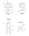
- FIGS. 6 to 8 Reference is made, in which the second securing element 30 is shown by itself.
- the outer contour of the second securing element 30 also has an approximately dodecagonal ground plan with two rounded outer surfaces, which corresponds to that of the first securing element 10 in its head region, as can be seen by comparing the two FIGS. 6 and 3 can recognize well.
- the two lateral wings 33, 34 of this plan form each form lateral projections on an octagonal central body 31, which has a greater length in the longitudinal direction than the two lateral wings 33, 34, as seen from FIG. 1 and FIG. 7 is recognizable.
- the second securing element 30 formed by the two lateral wings 33, 34 are intended to engage in recesses on the sleeve head of the closure of the firearm, which are provided in the functional state of the weapon for the front locking lugs of the chamber.
- a cylindrical shaft 32 At the dodecagonal lower surface of the body is followed in the longitudinal direction downwards, for example, a cylindrical shaft 32 at.
- a radial slot 36 see FIG. 1 and FIG. 7 ), so that there is an attack surface for a tool, in particular a screwdriver, by means of which one can rotate the second securing element 30 about its axis, so as to make the engagement with the first securing element 10.
- This special tool thus allows a feed of the fixing element in the longitudinal direction and a torque transmission. Since it is not commercially available, only a person skilled in the art is able to perform the screwing with the first securing element 10, which is in engagement with the second securing element.
- the recess 18, which receives the cylindrical thickening 35 of the second securing element 30, has a larger diameter than the upwardly open recess 17 of the first securing element 10, which receives the shaft 32, at the upper end of the recess 18 is an end-face abutment surface 24 formed, which prevents further displacement of the cylindrical thickening 35 in the recess in the axial direction (longitudinal direction).
- the second securing element 30 which is located in the recess 18 of the first securing element 10.
- the cylindrical thickening 35 is thus acted upon in the longitudinal direction upwards with a force and the pin 37 can no longer move out of the axial groove 20 back down in the radial groove 19.
- the safety device can no longer be removed by the owner of the firearm and the weapon is thus permanently secured.
- the sleeve receiving the chamber has a defined shape with sleeve head forward (towards the barrel) and sleeve bridge at the rear and the two securing elements 10, 30 shown in the figures are shaped such that they fit into the sleeve after removal of the chamber and at least partially results in a positive connection with the sleeve with inserted safety device. In this way, the firearm is permanently blocked by the security device. It is inventively possible in principle, the securing device in such a way that the determination by a screw-fastening element (see 40 in FIG. 9 ) can be done not only from the closure side (rear end of the weapon) but also through the barrel.
Landscapes
- Engineering & Computer Science (AREA)
- General Engineering & Computer Science (AREA)
- Aiming, Guidance, Guns With A Light Source, Armor, Camouflage, And Targets (AREA)
- Fuses (AREA)
Applications Claiming Priority (1)
| Application Number | Priority Date | Filing Date | Title |
|---|---|---|---|
| DE102011013537A DE102011013537A1 (de) | 2011-03-10 | 2011-03-10 | Sicherungseinrichtung für eine Schusswaffe |
Publications (3)
| Publication Number | Publication Date |
|---|---|
| EP2498041A2 true EP2498041A2 (fr) | 2012-09-12 |
| EP2498041A3 EP2498041A3 (fr) | 2015-05-13 |
| EP2498041B1 EP2498041B1 (fr) | 2017-10-04 |
Family
ID=45833197
Family Applications (1)
| Application Number | Title | Priority Date | Filing Date |
|---|---|---|---|
| EP12158710.9A Not-in-force EP2498041B1 (fr) | 2011-03-10 | 2012-03-09 | Dispositif de sécurisation pour une arme de tir |
Country Status (2)
| Country | Link |
|---|---|
| EP (1) | EP2498041B1 (fr) |
| DE (1) | DE102011013537A1 (fr) |
Cited By (1)
| Publication number | Priority date | Publication date | Assignee | Title |
|---|---|---|---|---|
| US11262147B2 (en) | 2019-08-23 | 2022-03-01 | AmmoBlock LLC | Firearm safety device |
Citations (1)
| Publication number | Priority date | Publication date | Assignee | Title |
|---|---|---|---|---|
| GB2286653A (en) | 1994-02-16 | 1995-08-23 | Gustavus Wilhelmus Grobler | A Gun Lock |
Family Cites Families (12)
| Publication number | Priority date | Publication date | Assignee | Title |
|---|---|---|---|---|
| US3352047A (en) * | 1966-07-11 | 1967-11-14 | Thomas M Mcdonnell | Gun trigger locking device |
| SE351720B (fr) * | 1971-04-01 | 1972-12-04 | Foerenade Fabriksverken | |
| DE3561215D1 (en) * | 1984-05-14 | 1988-01-28 | Nilsson Carl O Lennart | Device in a repeating rifle |
| GB8809946D0 (en) * | 1988-04-27 | 1988-06-02 | Braithwaite P | Locking device for firearms |
| GB2234047B (en) * | 1989-07-17 | 1993-07-28 | Camloc | Locking device |
| WO1996029560A2 (fr) * | 1995-03-15 | 1996-09-26 | Mul-T-Lock Technologies Ltd. | Verrouillage pour chambres et chargeurs d'armes |
| SE9800852L (sv) * | 1998-03-15 | 1999-09-16 | Magnus Lindskog | Förfarande och anordning vid ett slutstyckesförsett vapen |
| ITMI20011514A1 (it) * | 2001-07-17 | 2003-01-17 | Benelli Armi Spa | Dispositivo di sicurezza per armi da fuoco porttili |
| IL146983A (en) * | 2001-12-07 | 2010-02-17 | Mul T Lock Technologies Ltd | Apparatus and method for locking a firearm to prevent unauthorized use thereof |
| US6895707B2 (en) * | 2002-08-02 | 2005-05-24 | Visualock, Inc. | System for preventing accidental or unauthorized firing of a firearm |
| DE202008013965U1 (de) * | 2008-10-18 | 2009-01-08 | Stierhof, Detlev, Dipl.-Hdl. Dipl. STA | Blockiersystem für Einzelladerlang- und -kurzwaffen (ohne Magazinschacht), mit Kammerstängelverschluß |
| DE202010000312U1 (de) * | 2010-03-05 | 2010-05-20 | Hellebrandt, Manfred | Sicherungseinrichtung für eine Schusswaffe |
-
2011
- 2011-03-10 DE DE102011013537A patent/DE102011013537A1/de not_active Withdrawn
-
2012
- 2012-03-09 EP EP12158710.9A patent/EP2498041B1/fr not_active Not-in-force
Patent Citations (1)
| Publication number | Priority date | Publication date | Assignee | Title |
|---|---|---|---|---|
| GB2286653A (en) | 1994-02-16 | 1995-08-23 | Gustavus Wilhelmus Grobler | A Gun Lock |
Cited By (1)
| Publication number | Priority date | Publication date | Assignee | Title |
|---|---|---|---|---|
| US11262147B2 (en) | 2019-08-23 | 2022-03-01 | AmmoBlock LLC | Firearm safety device |
Also Published As
| Publication number | Publication date |
|---|---|
| DE102011013537A1 (de) | 2012-09-13 |
| EP2498041B1 (fr) | 2017-10-04 |
| EP2498041A3 (fr) | 2015-05-13 |
Similar Documents
| Publication | Publication Date | Title |
|---|---|---|
| EP2545623B1 (fr) | Presse-étoupe avec des moyens de serrage du blindage d'un câble | |
| EP2458317B1 (fr) | Fixation d'un poignée d'un fusil à répétition | |
| EP2261447B1 (fr) | Cadenas | |
| DE102015102073B3 (de) | Zylinder-Verschluss-Vorrichtung einer Repetier-Waffe | |
| EP4038337A1 (fr) | Unité de canon pour une arme à feu | |
| DE19957160C1 (de) | Sicherungsvorrichtung einer Schußwaffe gegen unbefugten Gebrauch | |
| EP2498041B1 (fr) | Dispositif de sécurisation pour une arme de tir | |
| WO2020077373A1 (fr) | Dispositif de montage pour une arme à feu | |
| EP3208567B1 (fr) | Amortisseur de bruit | |
| EP3015223B1 (fr) | Outil de demontage pour bougies de préchauffage | |
| DE202011003767U1 (de) | Sicherungseinrichtung für eine Schusswaffe | |
| DE102014223115A1 (de) | Vorrichtung zum Verspannen von Wirbeln der menschlichen Wirbelsäule | |
| EP4070027B1 (fr) | Système de culasse | |
| DE102010000644B4 (de) | Sicherungseinrichtung für eine Schusswaffe | |
| EP3112567B1 (fr) | Verrou avec dispositif d'activation ou de désactivation d'une fonction de jour pour le verrou | |
| WO2015169888A1 (fr) | Dispositif de liaison pour relier des éléments de montage | |
| DE102010023465B4 (de) | Verdrehsichere Befestigung des Hinterschafts einer Schusswaffe an dem Verschlussgehäuse | |
| DE202010000312U1 (de) | Sicherungseinrichtung für eine Schusswaffe | |
| DE10211882A1 (de) | Sicherung an Langwaffen mit einem Schlagbolzenschloss | |
| DE1932036B2 (de) | Zylinder-drehkammerverschluss fuer als einzellader ausgebildete gewehre | |
| EP3376151B1 (fr) | Culasse pour une arme à feu | |
| DE202017102910U1 (de) | Geräteanschluss | |
| DE2812751C2 (de) | Verschluß für automatische Gewehre mit Hahnschlagmechanismus | |
| DE19963326A1 (de) | Sperr.- und Blockadevorrichtung für Revolver und Selbstladehandfeuerwaffen | |
| EP2727685B1 (fr) | Dispositif de support pour une tête de vis avec noix |
Legal Events
| Date | Code | Title | Description |
|---|---|---|---|
| PUAI | Public reference made under article 153(3) epc to a published international application that has entered the european phase |
Free format text: ORIGINAL CODE: 0009012 |
|
| AK | Designated contracting states |
Kind code of ref document: A2 Designated state(s): AL AT BE BG CH CY CZ DE DK EE ES FI FR GB GR HR HU IE IS IT LI LT LU LV MC MK MT NL NO PL PT RO RS SE SI SK SM TR |
|
| AX | Request for extension of the european patent |
Extension state: BA ME |
|
| PUAL | Search report despatched |
Free format text: ORIGINAL CODE: 0009013 |
|
| AK | Designated contracting states |
Kind code of ref document: A3 Designated state(s): AL AT BE BG CH CY CZ DE DK EE ES FI FR GB GR HR HU IE IS IT LI LT LU LV MC MK MT NL NO PL PT RO RS SE SI SK SM TR |
|
| AX | Request for extension of the european patent |
Extension state: BA ME |
|
| RIC1 | Information provided on ipc code assigned before grant |
Ipc: F41A 17/44 20060101AFI20150407BHEP |
|
| 17P | Request for examination filed |
Effective date: 20151113 |
|
| RBV | Designated contracting states (corrected) |
Designated state(s): AL AT BE BG CH CY CZ DE DK EE ES FI FR GB GR HR HU IE IS IT LI LT LU LV MC MK MT NL NO PL PT RO RS SE SI SK SM TR |
|
| GRAP | Despatch of communication of intention to grant a patent |
Free format text: ORIGINAL CODE: EPIDOSNIGR1 |
|
| STAA | Information on the status of an ep patent application or granted ep patent |
Free format text: STATUS: GRANT OF PATENT IS INTENDED |
|
| INTG | Intention to grant announced |
Effective date: 20170411 |
|
| GRAS | Grant fee paid |
Free format text: ORIGINAL CODE: EPIDOSNIGR3 |
|
| GRAA | (expected) grant |
Free format text: ORIGINAL CODE: 0009210 |
|
| STAA | Information on the status of an ep patent application or granted ep patent |
Free format text: STATUS: THE PATENT HAS BEEN GRANTED |
|
| AK | Designated contracting states |
Kind code of ref document: B1 Designated state(s): AL AT BE BG CH CY CZ DE DK EE ES FI FR GB GR HR HU IE IS IT LI LT LU LV MC MK MT NL NO PL PT RO RS SE SI SK SM TR |
|
| REG | Reference to a national code |
Ref country code: GB Ref legal event code: FG4D Free format text: NOT ENGLISH |
|
| REG | Reference to a national code |
Ref country code: CH Ref legal event code: EP |
|
| REG | Reference to a national code |
Ref country code: AT Ref legal event code: REF Ref document number: 934457 Country of ref document: AT Kind code of ref document: T Effective date: 20171015 |
|
| REG | Reference to a national code |
Ref country code: IE Ref legal event code: FG4D Free format text: LANGUAGE OF EP DOCUMENT: GERMAN |
|
| REG | Reference to a national code |
Ref country code: DE Ref legal event code: R096 Ref document number: 502012011366 Country of ref document: DE |
|
| REG | Reference to a national code |
Ref country code: SE Ref legal event code: TRGR |
|
| REG | Reference to a national code |
Ref country code: NL Ref legal event code: FP |
|
| REG | Reference to a national code |
Ref country code: LT Ref legal event code: MG4D |
|
| REG | Reference to a national code |
Ref country code: FR Ref legal event code: PLFP Year of fee payment: 7 |
|
| PG25 | Lapsed in a contracting state [announced via postgrant information from national office to epo] |
Ref country code: LT Free format text: LAPSE BECAUSE OF FAILURE TO SUBMIT A TRANSLATION OF THE DESCRIPTION OR TO PAY THE FEE WITHIN THE PRESCRIBED TIME-LIMIT Effective date: 20171004 Ref country code: ES Free format text: LAPSE BECAUSE OF FAILURE TO SUBMIT A TRANSLATION OF THE DESCRIPTION OR TO PAY THE FEE WITHIN THE PRESCRIBED TIME-LIMIT Effective date: 20171004 Ref country code: NO Free format text: LAPSE BECAUSE OF FAILURE TO SUBMIT A TRANSLATION OF THE DESCRIPTION OR TO PAY THE FEE WITHIN THE PRESCRIBED TIME-LIMIT Effective date: 20180104 Ref country code: FI Free format text: LAPSE BECAUSE OF FAILURE TO SUBMIT A TRANSLATION OF THE DESCRIPTION OR TO PAY THE FEE WITHIN THE PRESCRIBED TIME-LIMIT Effective date: 20171004 |
|
| PGFP | Annual fee paid to national office [announced via postgrant information from national office to epo] |
Ref country code: CH Payment date: 20180326 Year of fee payment: 7 Ref country code: NL Payment date: 20180322 Year of fee payment: 7 Ref country code: GB Payment date: 20180326 Year of fee payment: 7 |
|
| PG25 | Lapsed in a contracting state [announced via postgrant information from national office to epo] |
Ref country code: GR Free format text: LAPSE BECAUSE OF FAILURE TO SUBMIT A TRANSLATION OF THE DESCRIPTION OR TO PAY THE FEE WITHIN THE PRESCRIBED TIME-LIMIT Effective date: 20180105 Ref country code: LV Free format text: LAPSE BECAUSE OF FAILURE TO SUBMIT A TRANSLATION OF THE DESCRIPTION OR TO PAY THE FEE WITHIN THE PRESCRIBED TIME-LIMIT Effective date: 20171004 Ref country code: RS Free format text: LAPSE BECAUSE OF FAILURE TO SUBMIT A TRANSLATION OF THE DESCRIPTION OR TO PAY THE FEE WITHIN THE PRESCRIBED TIME-LIMIT Effective date: 20171004 Ref country code: BG Free format text: LAPSE BECAUSE OF FAILURE TO SUBMIT A TRANSLATION OF THE DESCRIPTION OR TO PAY THE FEE WITHIN THE PRESCRIBED TIME-LIMIT Effective date: 20180104 Ref country code: HR Free format text: LAPSE BECAUSE OF FAILURE TO SUBMIT A TRANSLATION OF THE DESCRIPTION OR TO PAY THE FEE WITHIN THE PRESCRIBED TIME-LIMIT Effective date: 20171004 Ref country code: IS Free format text: LAPSE BECAUSE OF FAILURE TO SUBMIT A TRANSLATION OF THE DESCRIPTION OR TO PAY THE FEE WITHIN THE PRESCRIBED TIME-LIMIT Effective date: 20180204 |
|
| PGFP | Annual fee paid to national office [announced via postgrant information from national office to epo] |
Ref country code: SE Payment date: 20180326 Year of fee payment: 7 Ref country code: FR Payment date: 20180326 Year of fee payment: 7 |
|
| REG | Reference to a national code |
Ref country code: DE Ref legal event code: R097 Ref document number: 502012011366 Country of ref document: DE |
|
| PG25 | Lapsed in a contracting state [announced via postgrant information from national office to epo] |
Ref country code: DK Free format text: LAPSE BECAUSE OF FAILURE TO SUBMIT A TRANSLATION OF THE DESCRIPTION OR TO PAY THE FEE WITHIN THE PRESCRIBED TIME-LIMIT Effective date: 20171004 Ref country code: EE Free format text: LAPSE BECAUSE OF FAILURE TO SUBMIT A TRANSLATION OF THE DESCRIPTION OR TO PAY THE FEE WITHIN THE PRESCRIBED TIME-LIMIT Effective date: 20171004 Ref country code: CZ Free format text: LAPSE BECAUSE OF FAILURE TO SUBMIT A TRANSLATION OF THE DESCRIPTION OR TO PAY THE FEE WITHIN THE PRESCRIBED TIME-LIMIT Effective date: 20171004 Ref country code: SK Free format text: LAPSE BECAUSE OF FAILURE TO SUBMIT A TRANSLATION OF THE DESCRIPTION OR TO PAY THE FEE WITHIN THE PRESCRIBED TIME-LIMIT Effective date: 20171004 |
|
| PLBE | No opposition filed within time limit |
Free format text: ORIGINAL CODE: 0009261 |
|
| STAA | Information on the status of an ep patent application or granted ep patent |
Free format text: STATUS: NO OPPOSITION FILED WITHIN TIME LIMIT |
|
| PG25 | Lapsed in a contracting state [announced via postgrant information from national office to epo] |
Ref country code: PL Free format text: LAPSE BECAUSE OF FAILURE TO SUBMIT A TRANSLATION OF THE DESCRIPTION OR TO PAY THE FEE WITHIN THE PRESCRIBED TIME-LIMIT Effective date: 20171004 Ref country code: SM Free format text: LAPSE BECAUSE OF FAILURE TO SUBMIT A TRANSLATION OF THE DESCRIPTION OR TO PAY THE FEE WITHIN THE PRESCRIBED TIME-LIMIT Effective date: 20171004 Ref country code: RO Free format text: LAPSE BECAUSE OF FAILURE TO SUBMIT A TRANSLATION OF THE DESCRIPTION OR TO PAY THE FEE WITHIN THE PRESCRIBED TIME-LIMIT Effective date: 20171004 Ref country code: IT Free format text: LAPSE BECAUSE OF FAILURE TO SUBMIT A TRANSLATION OF THE DESCRIPTION OR TO PAY THE FEE WITHIN THE PRESCRIBED TIME-LIMIT Effective date: 20171004 |
|
| 26N | No opposition filed |
Effective date: 20180705 |
|
| PG25 | Lapsed in a contracting state [announced via postgrant information from national office to epo] |
Ref country code: MT Free format text: LAPSE BECAUSE OF FAILURE TO SUBMIT A TRANSLATION OF THE DESCRIPTION OR TO PAY THE FEE WITHIN THE PRESCRIBED TIME-LIMIT Effective date: 20171004 |
|
| PG25 | Lapsed in a contracting state [announced via postgrant information from national office to epo] |
Ref country code: MC Free format text: LAPSE BECAUSE OF FAILURE TO SUBMIT A TRANSLATION OF THE DESCRIPTION OR TO PAY THE FEE WITHIN THE PRESCRIBED TIME-LIMIT Effective date: 20171004 Ref country code: SI Free format text: LAPSE BECAUSE OF FAILURE TO SUBMIT A TRANSLATION OF THE DESCRIPTION OR TO PAY THE FEE WITHIN THE PRESCRIBED TIME-LIMIT Effective date: 20171004 |
|
| REG | Reference to a national code |
Ref country code: BE Ref legal event code: MM Effective date: 20180331 |
|
| REG | Reference to a national code |
Ref country code: IE Ref legal event code: MM4A |
|
| PG25 | Lapsed in a contracting state [announced via postgrant information from national office to epo] |
Ref country code: LU Free format text: LAPSE BECAUSE OF NON-PAYMENT OF DUE FEES Effective date: 20180309 |
|
| PG25 | Lapsed in a contracting state [announced via postgrant information from national office to epo] |
Ref country code: IE Free format text: LAPSE BECAUSE OF NON-PAYMENT OF DUE FEES Effective date: 20180309 |
|
| PG25 | Lapsed in a contracting state [announced via postgrant information from national office to epo] |
Ref country code: BE Free format text: LAPSE BECAUSE OF NON-PAYMENT OF DUE FEES Effective date: 20180331 |
|
| REG | Reference to a national code |
Ref country code: AT Ref legal event code: MM01 Ref document number: 934457 Country of ref document: AT Kind code of ref document: T Effective date: 20180309 |
|
| REG | Reference to a national code |
Ref country code: SE Ref legal event code: EUG |
|
| PG25 | Lapsed in a contracting state [announced via postgrant information from national office to epo] |
Ref country code: SE Free format text: LAPSE BECAUSE OF NON-PAYMENT OF DUE FEES Effective date: 20190310 Ref country code: AT Free format text: LAPSE BECAUSE OF NON-PAYMENT OF DUE FEES Effective date: 20180309 |
|
| REG | Reference to a national code |
Ref country code: CH Ref legal event code: PL |
|
| REG | Reference to a national code |
Ref country code: NL Ref legal event code: MM Effective date: 20190401 |
|
| GBPC | Gb: european patent ceased through non-payment of renewal fee |
Effective date: 20190309 |
|
| PG25 | Lapsed in a contracting state [announced via postgrant information from national office to epo] |
Ref country code: CH Free format text: LAPSE BECAUSE OF NON-PAYMENT OF DUE FEES Effective date: 20190331 Ref country code: LI Free format text: LAPSE BECAUSE OF NON-PAYMENT OF DUE FEES Effective date: 20190331 Ref country code: NL Free format text: LAPSE BECAUSE OF NON-PAYMENT OF DUE FEES Effective date: 20190401 Ref country code: GB Free format text: LAPSE BECAUSE OF NON-PAYMENT OF DUE FEES Effective date: 20190309 |
|
| PG25 | Lapsed in a contracting state [announced via postgrant information from national office to epo] |
Ref country code: FR Free format text: LAPSE BECAUSE OF NON-PAYMENT OF DUE FEES Effective date: 20190331 |
|
| PG25 | Lapsed in a contracting state [announced via postgrant information from national office to epo] |
Ref country code: TR Free format text: LAPSE BECAUSE OF FAILURE TO SUBMIT A TRANSLATION OF THE DESCRIPTION OR TO PAY THE FEE WITHIN THE PRESCRIBED TIME-LIMIT Effective date: 20171004 |
|
| PG25 | Lapsed in a contracting state [announced via postgrant information from national office to epo] |
Ref country code: HU Free format text: LAPSE BECAUSE OF FAILURE TO SUBMIT A TRANSLATION OF THE DESCRIPTION OR TO PAY THE FEE WITHIN THE PRESCRIBED TIME-LIMIT; INVALID AB INITIO Effective date: 20120309 Ref country code: PT Free format text: LAPSE BECAUSE OF FAILURE TO SUBMIT A TRANSLATION OF THE DESCRIPTION OR TO PAY THE FEE WITHIN THE PRESCRIBED TIME-LIMIT Effective date: 20171004 |
|
| PG25 | Lapsed in a contracting state [announced via postgrant information from national office to epo] |
Ref country code: CY Free format text: LAPSE BECAUSE OF FAILURE TO SUBMIT A TRANSLATION OF THE DESCRIPTION OR TO PAY THE FEE WITHIN THE PRESCRIBED TIME-LIMIT Effective date: 20171004 Ref country code: MK Free format text: LAPSE BECAUSE OF NON-PAYMENT OF DUE FEES Effective date: 20171004 |
|
| PG25 | Lapsed in a contracting state [announced via postgrant information from national office to epo] |
Ref country code: AL Free format text: LAPSE BECAUSE OF FAILURE TO SUBMIT A TRANSLATION OF THE DESCRIPTION OR TO PAY THE FEE WITHIN THE PRESCRIBED TIME-LIMIT Effective date: 20171004 |
|
| PGFP | Annual fee paid to national office [announced via postgrant information from national office to epo] |
Ref country code: DE Payment date: 20200331 Year of fee payment: 9 |
|
| REG | Reference to a national code |
Ref country code: DE Ref legal event code: R082 Ref document number: 502012011366 Country of ref document: DE Representative=s name: FARAGO PATENTANWALTS- UND RECHTSANWALTSGESELLS, DE |
|
| REG | Reference to a national code |
Ref country code: DE Ref legal event code: R119 Ref document number: 502012011366 Country of ref document: DE |
|
| PG25 | Lapsed in a contracting state [announced via postgrant information from national office to epo] |
Ref country code: DE Free format text: LAPSE BECAUSE OF NON-PAYMENT OF DUE FEES Effective date: 20211001 |