EP2498055B2 - Verwaltungssystem für unbemannte Luftfahrzeuge - Google Patents
Verwaltungssystem für unbemannte Luftfahrzeuge Download PDFInfo
- Publication number
- EP2498055B2 EP2498055B2 EP11181017.2A EP11181017A EP2498055B2 EP 2498055 B2 EP2498055 B2 EP 2498055B2 EP 11181017 A EP11181017 A EP 11181017A EP 2498055 B2 EP2498055 B2 EP 2498055B2
- Authority
- EP
- European Patent Office
- Prior art keywords
- aircraft
- route
- target points
- control system
- reached
- Prior art date
- Legal status (The legal status is an assumption and is not a legal conclusion. Google has not performed a legal analysis and makes no representation as to the accuracy of the status listed.)
- Active
Links
Images


Classifications
-
- G—PHYSICS
- G01—MEASURING; TESTING
- G01C—MEASURING DISTANCES, LEVELS OR BEARINGS; SURVEYING; NAVIGATION; GYROSCOPIC INSTRUMENTS; PHOTOGRAMMETRY OR VIDEOGRAMMETRY
- G01C23/00—Combined instruments indicating more than one navigational value, e.g. for aircraft; Combined measuring devices for measuring two or more variables of movement, e.g. distance, speed or acceleration
-
- G—PHYSICS
- G05—CONTROLLING; REGULATING
- G05D—SYSTEMS FOR CONTROLLING OR REGULATING NON-ELECTRIC VARIABLES
- G05D1/00—Control of position, course, altitude or attitude of land, water, air or space vehicles, e.g. using automatic pilots
- G05D1/0088—Control of position, course, altitude or attitude of land, water, air or space vehicles, e.g. using automatic pilots characterized by the autonomous decision making process, e.g. artificial intelligence, predefined behaviours
-
- G—PHYSICS
- G05—CONTROLLING; REGULATING
- G05D—SYSTEMS FOR CONTROLLING OR REGULATING NON-ELECTRIC VARIABLES
- G05D1/00—Control of position, course, altitude or attitude of land, water, air or space vehicles, e.g. using automatic pilots
- G05D1/10—Simultaneous control of position or course in three dimensions
- G05D1/101—Simultaneous control of position or course in three dimensions specially adapted for aircraft
- G05D1/106—Change initiated in response to external conditions, e.g. avoidance of elevated terrain or of no-fly zones
Definitions
- the embodiments described herein relates generally to unmanned aerial vehicles and, in particular, to a method and apparatus for managing an unmanned aerial vehicle. Still more particularly, the present disclosure relates to a method and apparatus for managing an unmanned aerial vehicle during flight
- Unmanned aerial vehicles are aircraft that fly without a human operator onboard the aircraft. Un-manned aerial vehicles are used for a number of different purposes. Unmanned aerial vehicles may be used by military organizations to perform surveillance, reconnaissance, target acquisition, attacks on targets, and other suitable operations. Additionally, unmanned aerial vehicles also may be used in non-military applications. These applications include fire-fighting, security, and/or other suitable types of operations.
- Unmanned aerial vehicles may have many different shapes, sizes, configurations, and characteristics. Unmanned aerial vehicles may be controlled from a remote location or fly autonomously using a program with a flight plan run by the program on the unmanned aerial vehicle.
- an unmanned aerial vehicle may perform a mission at lower altitudes in hostile environments.
- An unmanned aerial vehicle may have to deviate from a desired route to avoid exposure to threats that may damage or destroy the unmanned aerial vehicle. These threats also may include jamming or other interruptions in the communications links used by the unmanned aerial vehicle.
- missions may include multiple waypoints through which an unmanned aerial vehicle may fly.
- the unmanned aerial vehicle may collect information or perform other operations at or near these way-points.
- the route of the unmanned aerial vehicle may change such that reaching the different waypoints to perform operations may be unfeasible with respect to the resources of the unmanned aerial vehicle, such as fuel.
- unmanned aerial vehicles may fly a route using the waypoints that may be followed. These waypoints may include points other than those used to perform different operations.
- a remote operator may interrupt the route being flown by the unmanned aerial vehicle to take into account hostile environments. Additionally, the remote operator also may make other changes to the waypoints to take into account available resources.
- This type of process requires the remote operator to monitor the unmanned aerial vehicle.
- the position of the unmanned aerial vehicle and information about potential hostile environments are used by the operator to determine whether changes are needed. These types of operations may take more time than desired, as well as require additional resources to operate the unmanned aerial vehicle.
- US 5,838,262 discloses a virtual image display system for aircraft to identify threat systems that are proximal the flight path.
- the invention is set out in method claim 1 and apparatus claim 10.
- the different advantageous embodiments recognize and take into account a number of different considerations. For example, the different advantageous embodiments recognize and take into account that the use of a remote operator for an unmanned aerial vehicle may be undesirable in certain situations. The different advantageous embodiments recognize and take into account that, in some cases, an environment may make communications between the remote operator and the unmanned aerial vehicle difficult or impossible. For example, jamming or other interruptions of unmanned aerial vehicle communications may make it impossible for the remote operator to change the route of an unmanned aerial vehicle.
- the different advantageous embodiments recognize and take into account that the use of waypoints for correcting the flight of an unmanned aerial vehicle may allow the unmanned aerial vehicle to perform a mission without a remote operator.
- the different advantageous embodiments recognize and take into account, however, that other conditions may result in the unmanned aerial vehicle being unable to perform a mission, even with the use of a route containing waypoints.
- an unmanned aerial vehicle may be damaged by hostile personnel when following a route programmed for the unmanned aerial vehicle.
- the different advantageous embodiments recognize and take into account that it would be advantageous to provide an unmanned aerial vehicle with a capability to detect environmental conditions that may require a change to a route of the unmanned aerial vehicle to avoid or reduce the effects of an undesired environment. Further, the different advantageous embodiments also recognize and take into account that it would be desirable to provide an unmanned aerial vehicle with a capability to allocate resources in a manner to perform as much of a mission as possible if changes to a route are needed based on environmental conditions.
- the different advantageous embodiments provide a method and apparatus for managing a flight of an aircraft.
- Conditions in an environment around the aircraft are monitored during the flight of the aircraft on a route having a number of target points.
- current resources for the aircraft are identified.
- a determination is made as to whether changing the route reduces the number of target points that can be reached based on the current resources for the aircraft.
- the route is changed to include a portion of the number of target points using the condition and a policy.
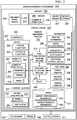
- mission management environment 100 includes control station 102, unmanned aerial vehicle 104, helicopter 106, aircraft 108, and aircraft 110.
- control station 102 takes the form of ground vehicle 112 in this example.
- An operator may use a control system associated with ground vehicle 112 to manage missions performed by at least one of unmanned aerial vehicle 104, helicopter 106, aircraft 108, and aircraft 110.
- a control system may be associated with ground vehicle 112 by being a computer system located in ground vehicle 112.
- the phrase "at least one of”, when used with a list of items, means that different combinations of one or more of the listed items may be used and only one of each item in the list may be needed.
- “at least one of item A, item B, and item C” may include, for example, without limitation, item A or item A and item B. This example also may include item A, item B, and item C or item B and item C.
- control system 102 exchanges information with unmanned aerial vehicle 104, helicopter 106, aircraft 108, and aircraft 110 using wireless communication links 116, 114, 120, and 118, respectively. This information is exchanged such that unmanned aerial vehicle 104, helicopter 106, aircraft 108, and aircraft 110 may use mission management process 122 to plan and manage missions.
- Mission management process 122 is run on unmanned aerial vehicle 104, helicopter 106, aircraft 108, and aircraft 110. Further, in some illustrative examples, a portion of mission management process 122 may run on the control system in control station 102. A portion may be some or all of mission management process 122 in these illustrative examples.
- mission management process 122 includes route analysis and planning process 124, resource allocation process 126, and landing zone identification process 128. These processes are described in greater detail in the figures below.
- mission management environment 100 in Figure 1 is an example of one implementation for mission management environment 200 in Figure 2 .
- Mission management environment 200 includes aircraft 202 and control system 204 in this illustrative example.
- Unmanned aerial vehicle 104, helicopter 106, aircraft 108, and aircraft 110 in Figure 1 are examples of implementations for aircraft 202.
- aircraft 202 takes the form of unmanned aerial vehicle 206.
- aircraft 202 may take the form of manned aircraft 207 or some other suitable type of aircraft.
- control system 204 manages mission 208 for flight 210 of aircraft 202.
- Mission 208 includes performing number of operations 209.
- Number of operations 209 include surveillance, reconnaissance, target acquisition, target destruction or weapons deployment.
- control system 204 may take a number of different forms.
- control system 204 may be selected from at least one of a processor unit, a computer with a processor unit, a processor unit with a number of hardware units, and an application specific integrated circuit.
- control system 204 is located in aircraft 202. However, in some illustrative examples, at least a portion of control system 204 may be located in control station 211. Control station 211 may be selected from at least one of a ground station, a ground vehicle, an aerial station, a satellite station, and/or some other suitable type of control station.
- mission management process 212 runs on control system 204. Depending on the implementation and configuration for control system 204, mission management process 212 may run onboard and/or off-board aircraft 202. Mission management process 212 is configured to plan and manage mission 208 for flight 210 of aircraft 202.
- Mission management process 212 includes route analysis and planning process 214, resource allocation process 216, and landing zone process 218. These three processes are integrated in mission management process 212 to provide a capability for control system 204 to dynamically manage mission 208 for flight 210 of aircraft 202.
- dynamically managing mission 208 involves managing mission 208 as mission 208 occurs during flight 210.
- the management may occur substantially in real-time and continuously during flight 210 of aircraft 202.
- route analysis and planning process 214 manages route 220 for flight 210 of aircraft 202.
- Route 220 includes vertical flight path 222 and horizontal flight path 224.
- Vertical flight path 222 includes the various altitudes at which aircraft 202 will fly during flight 210.
- Horizontal flight path 224 includes the geographic coordinates through which aircraft 202 will fly during flight 210. These geographic coordinates may be in the form of, for example, latitude and longitude.
- Route analysis and planning process 214 plans and manages route 220 to provide increased survivability and reduced undesired exposure of aircraft 202. For example, without limitation, route analysis and planning process 214 plans and manages route 220 based on terrain 226 over which aircraft 202 flies during flight 210.
- route analysis and planning process 214 plans and manages route 220 such that undesired exposure of aircraft 202 during flight 210 is reduced.
- Undesired exposure includes exposure to potential threats.
- Potential threats may include, for example, without limitation, electronic surveillance systems, hostile personnel, sensor systems in hostile environments, radar and/or optically guided missiles, anti-aircraft artillery, and/or other suitable types of threats.
- route analysis and planning process 214 manages vertical flight path 222 for route 220 to reduce the possibility that hostile radar surveillance systems may detect aircraft 202 during flight 210. Further, route analysis and planning process 214 may manage route 220 based on terrain 226 over which aircraft 202 flies to reduce undesired detection of aircraft 202.
- route analysis and planning process 214 monitors conditions 228 in environment 230 around aircraft 202 during flight 210, while aircraft 202 is on route 220.
- conditions 228 may include, for example, without limitation, threat condition 232, weather condition 234, terrain condition 236, and/or other suitable conditions.
- Route analysis and planning process 214 monitors conditions 228 in environment 230 using information 238.
- Information 238 includes weather information 231, digital elevation model 233, sensor data 235, detectability 237, electronic order of battle 239, and/or other suitable information.
- digital elevation model 233 is a digital representation of terrain 226 over which aircraft 202 flies.
- Detectability 237 includes radar cross-section data, an acoustic signature of aircraft 202, an optical signature of aircraft 202, visibility of aircraft 202 due to physical specifications and/or performance, and/or other information.
- Radar cross-section data is a measure of how detectable aircraft 202 is with respect to radar.
- Electronic order of battle 239 includes an identification of locations of threats, characteristics of the threats, a prioritization of the threats, and/or other suitable information related to the threats. These threats may include, for example, without limitation, signal intelligence emitters that may be capable of detecting aircraft 202. Electronic order of battle 239 also includes an identification of communications intelligence and/or electronic signals intelligence that may pose a threat to aircraft 202. Electronic order of battle 239 may be updated during flight of aircraft 202 in response to threats that are identified during the flight.
- sensor data 235 is generated by sensor system 240.
- Sensor system 240 is associated with aircraft 202 in these examples.
- a first component may be considered to be associated with a second component by being secured to the second component, bonded to the second component, fastened to the second component, associated with the second component by a combination of the above, and/or connected to the second component in some other suitable manner.
- the first component also may be connected to the second component by using a third component.
- the first component may also be considered to be associated with the second component by being formed as part of and/or as an extension of the second component.
- Model 241 of aircraft 202 includes information about aircraft 202.
- model 241 of aircraft 202 includes aircraft performance information 243, aircraft resource information 245, and/or other suitable information.
- This other suitable information may include, for example, without limitation, specifications for aircraft 202, an identification of parts in aircraft 202, a manufacturer of aircraft 202, and/or other suitable information.
- Aircraft performance information 243 includes aircraft kinematics information, performance capabilities in dead-stick mode, a maximum speed for aircraft 202, turning capabilities, energy use of aircraft 202, and/or other types of performance information.
- Aircraft resource information 245 includes information about fuel, engine power, available weapons, and/or other types of resource information.
- resource allocation process 216 plans and manages number of waypoints 242 and number of target points 244 for route 220.
- Number of waypoints 242 includes locations identified along route 220 for flight 210. These waypoints may be defined in terms of geographic coordinates and/or altitude.
- Number of target points 244 are points within number of waypoints 242 along route 220 at which aircraft 202 performs number of operations 209.
- a target point is a point at which aircraft 202 collects surveillance information, generates sensor information, deploys a weapon or attacks a target.
- Resource allocation process 216 determines order 246 for reaching number of target points 244 and/or number of waypoints 242. Further, resource allocation process 216 determines which portion of number of target points 244 are to be reached during flight 210 based on changes to route 220 made by route analysis and planning process 214. This determination may be based on conditions 228, model 241, information 238, and/or policy 248.
- policy 248 includes a number of rules for performing mission 208 during flight 210 of aircraft 202.
- policy 248 may include a rule indicating a minimum number of target points in number of target points 244 required to be reached during a single flight of aircraft 202.
- Policy 248 may also identify priorities 250 for each of number of target points 244. These priorities may change during flight 210 as a function of time, changes in environment 230, changes to the objectives of mission 208, and/or other suitable factors.
- resource allocation process 216 determines portion 247 of number of target points 244 to be reached during flight 210 and order 246 for portion 247 of number of target points 244. Order 246 and/or portion 247 are managed dynamically during flight 210 of aircraft 202.
- route analysis and planning process 214 may make changes to route 220. For example, route analysis and planning process 214 may change route 220 to new route 225 based on current location 227 of aircraft 202 and conditions 228.
- landing zone process 218 identifies attainable landing zones 252 for aircraft 202 during flight 210. Attainable landing zones 252 may be identified by an operator of aircraft 202 prior to and/or during flight 210 in these examples.
- Attainable landing zones 252 include locations along route 220 that may be reachable in a dead-stick mode and have terrain suitable for landing aircraft 202.
- attainable landing zones 252 include locations in which aircraft 202 can physically land.
- attainable landing zones 252 also include landing zones in which aircraft 202 is less likely to be detected during landing.
- landing zone process 218 may select landing zone 254 from attainable landing zones 252 and/or other landing zones in response to an in-flight situation.
- This in-flight situation may be, for example, an engine out, a problem with a critical aircraft system, low fuel, damage to aircraft 202, and/or some other type of situation.
- landing zone process 218 may select landing zone 254 to increase the possibility of recovery of aircraft 202 after landing.
- landing zone 254 may be selected such that landing of aircraft 202 does not result in undesired collateral damage.
- landing zone process 218 may also select landing zone 254 in response to a need to self-destruct aircraft 202. For example, aircraft 202 may need to be destroyed during landing such that hostile personnel are unable to retrieve any part of aircraft 202. Landing zone process 218 may select landing zone 254 such that aircraft 202 may be undetected during landing and land in a location that will allow aircraft 202 to be completely destroyed.
- mission management environment 200 in Figure 2 is not meant to imply physical or architectural limitations to the manner in which different advantageous embodiments may be implemented.
- Other components in addition to and/or in place of the ones illustrated may be used. Some components may be unnecessary in some advantageous embodiments.
- the blocks are presented to illustrate some functional components. One or more of these blocks may be combined and/or divided into different blocks when implemented in different advantageous embodiments.
- control system 204 may take the form of a number of computers. Further, in some examples, processes in addition to the processes described within mission management process 212 may run on control system 204 to manage mission 208 during flight 210 of aircraft 202.
- mission management process 212 may manage a mission to be performed by more than one aircraft. For example, without limitation, at least a portion of mission management process 212 may run on a computer in control station 211 to manage mission 208 to be performed by aircraft 202 and two other aircraft. Further, mission management process 212 may manage multiple missions being performed by multiple aircraft.
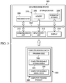
- data processing system 300 is an example of one implementation for control system 204 in Figure 2 .
- data processing system 300 includes communications fabric 302, which provides communications between processor unit 304, memory 306, persistent storage 308, communications unit 310, input/output (I/O) unit 312, and display 314.
- communications fabric 302 provides communications between processor unit 304, memory 306, persistent storage 308, communications unit 310, input/output (I/O) unit 312, and display 314.
- Processor unit 304 serves to execute instructions for software that may be loaded into memory 306.
- Processor unit 304 may be a number of processors, a multi-processor core, or some other type of processor, depending on the particular implementation.
- a number, as used herein with reference to an item, means one or more items.
- processor unit 304 may be implemented using a number of heterogeneous processor systems in which a main processor is present with secondary processors on a single chip.
- processor unit 304 may be a symmetric multiprocessor system containing multiple processors of the same type.
- Memory 306 and persistent storage 308 are examples of storage devices 316.
- a storage device is any piece of hardware that is capable of storing information, such as, for example, without limitation, data, program code in functional form, and/or other suitable information either on a temporary basis and/or a permanent basis.
- Storage devices 316 may also be referred to as computer readable storage devices in these examples.
- Memory 306, in these examples, may be, for example, a random access memory or any other suitable volatile or non-volatile storage device.
- Persistent storage 308 may take various forms, depending on the particular implementation.
- persistent storage 308 may contain one or more components or devices.
- persistent storage 308 may be a hard drive, a flash memory, a rewritable optical disk, a rewritable magnetic tape, or some combination of the above.
- the media used by persistent storage 308 also may be removable.
- a removable hard drive may be used for persistent storage 308.
- Communications unit 310 in these examples, provides for communications with other data processing systems or devices.
- communications unit 310 is a network interface card.
- Communications unit 310 may provide communications through the use of either or both physical and wireless communications links.
- Input/output unit 312 allows for input and output of data with other devices that may be connected to data processing system 300.
- input/output unit 312 may provide a connection for user input through a keyboard, a mouse, and/or some other suitable input device. Further, input/output unit 312 may send output to a printer.
- Display 314 provides a mechanism to display information to a user.
- Instructions for the operating system, applications, and/or programs may be located in storage devices 316, which are in communication with processor unit 304 through communications fabric 302. In these illustrative examples, the instructions are in a functional form on persistent storage 308. These instructions may be loaded into memory 306 for execution by processor unit 304. The processes of the different embodiments may be performed by processor unit 304 using computer implemented instructions, which may be located in a memory, such as memory 306.
- program code computer usable program code
- computer readable program code that may be read and executed by a processor in processor unit 304.
- the program code in the different embodiments may be embodied on different physical or computer readable storage media, such as memory 306 or persistent storage 308.
- Program code 318 is located in a functional form on computer readable media 320 that is selectively removable and may be loaded onto or transferred to data processing system 300 for execution by processor unit 304.
- Program code 318 and computer readable media 320 form computer program product 322 in these examples.
- computer readable media 320 may be computer readable storage media 324 or computer readable signal media 326.
- Computer readable storage media 324 may include, for example, an optical or magnetic disk that is inserted or placed into a drive or other device that is part of persistent storage 308 for transfer onto a storage device, such as a hard drive, that is part of persistent storage 308.
- Computer readable storage media 324 also may take the form of a persistent storage, such as a hard drive, a thumb drive, or a flash memory, that is connected to data processing system 300.
- computer readable storage media 324 may not be removable from data processing system 300.
- computer readable storage media 324 is a non-transitory computer readable storage medium.
- program code 318 may be transferred to data processing system 300 using computer readable signal media 326.
- Computer readable signal media 326 may be, for example, a propagated data signal containing program code 318.
- Computer readable signal media 326 may be an electromagnetic signal, an optical signal, and/or any other suitable type of signal. These signals may be transmitted over communication links, such as wireless communication links, optical fiber cable, coaxial cable, a wire, and/or any other suitable type of communication link.
- the communication link and/or the connection may be physical or wireless in the illustrative examples.
- program code 318 may be downloaded over a network to persistent storage 308 from another device or data processing system through computer readable signal media 326 for use within data processing system 300.
- program code stored in a computer readable storage medium in a server data processing system may be downloaded over a network from the server to data processing system 300.
- the data processing system providing program code 318 may be a server computer, a client computer, or some other device capable of storing and transmitting program code 318.
- data processing system 300 The different components illustrated for data processing system 300 are not meant to provide architectural limitations to the manner in which different embodiments may be implemented.
- the different advantageous embodiments may be implemented in a data processing system including components in addition to or in place of those illustrated for data processing system 300.
- the data processing system may include organic components integrated with inorganic components and/or may be comprised entirely of organic components excluding a human being.
- a storage device may be comprised of an organic semiconductor.
- a storage device in data processing system 300 is any hardware apparatus that may store data.
- Memory 306, persistent storage 308, and computer readable media 320 are examples of storage devices in a tangible form.
- a bus system may be used to implement communications fabric 302 and may be comprised of one or more buses, such as a system bus or an input/output bus.
- the bus system may be implemented using any suitable type of architecture that provides for a transfer of data between different components or devices attached to the bus system.
- a communications unit may include one or more devices used to transmit and receive data, such as a modem or a network adapter.
- a memory may be, for example, memory 306, or a cache, such as found in an interface and memory controller hub that may be present in communications fabric 302.
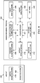
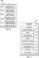
- Mission management process 400 is an example of one implementation for mission management process 212 in Figure 2 . Further, mission management process 400 may run on a computer, such as data processing system 300 in Figure 3 .
- Mission management process 400 includes mission manager 401, route analysis and planning process 402, resource allocation process 404, landing zone process 406, threat generation model 408, flight model 410, on-board threat detection 412, and off-board threat information 414. As depicted, mission manager 401 integrates information from each of route analysis and planning process 402, resource allocation process 404, landing zone process 406, threat generation model 408, flight model 410, on-board threat detection 412, and off-board threat information 414 to manage a mission for aircraft 415.
- mission manager 401 may exchange information with other systems on aircraft 415 using aircraft system interface 416.
- Aircraft system interface 416 may be a hardware and/or software interface in these examples.
- aircraft system interface 416 allows mission manager 401 to receive in- formation from inertial navigation system 418. Further, aircraft system interface 416 allows mission manager 401 to send information to navigation system 420. For example, mission manager 401 may send updated route information to navigation system 420 substantially in real-time and continuously during the flight of aircraft 415.
- Threat generation model 408 includes information about potential threats. For example, for a surface to air missile threat, threat generation model 408 may include a frequency of the radar associated with the missile, the type of seeker, a footprint range, and/or other suitable information about the surface to air missile threat.
- Flight model 410 is an example of one implementation for model 241 in Figure 2 .
- Flight model 410 includes information, such as, without limitation, aircraft performance information, aircraft resource information, aircraft specifications, and/or other suitable information.
- on-board threat detection 412 comprises an identification of potential threats detected using sensor systems on-board aircraft 415 in this example.
- on-board threat detection 412 may include an identification of potential threats made using video camera systems, radar systems, infrared systems, and/or other suitable types of on-board sensor systems.
- Off-board threat information 414 comprises information provided by a source off-board aircraft 415.
- off-board threat information 414 may include information provided by a control station, surveillance aircraft, communications intelligence, signals intelligence, foot soldiers performing surveillance, and/or other off-board sources.
- routing analysis and planning process 500 is an example of one implementation for route analysis and planning process 214 in Figure 2 .
- Routing analysis and planning process 500 forms desired route 502 based on various sources of information. Desired route 502 is an example of one implementation for route 220 in Figure 2 .
- Routing analysis and planning process 500 uses information 504, mission parameters 506, control features 508, and objective functions weights 510 to form desired route 502.
- Information 504 may be an example of information 238 in Figure 2 .
- Information 504 includes digital elevation model 512, sensor data 514, electronic order of battle 516, and model 518.
- Electronic order of battle 516 includes an identification of threats and information about the threats that may be encountered during the mission.
- Model 518 includes aircraft signature 520, aircraft performance 522, and aircraft resources 524.
- mission parameters 506 include, for example, without limitation, a beginning fuel level, time constraints, a minimum altitude above ground at which the aircraft can fly, and/or other suitable parameters.
- Mission parameters 506 may be selected based on the type of mission for the aircraft, safety guidelines, and/or other suitable factors. For example, flying below the minimum altitude for the aircraft may reduce the safety of the aircraft, reduce performance of the aircraft, and/or generate errors in the geospatial data obtained by the aircraft.
- Control features 508 are geospatial features that control how routing analysis and planning process 500 forms desired route 502.
- control features 508 may include geospatial polygons and/or closed polygonal chains that represent areas that should be avoided by the aircraft during flight.
- a closed polygonal chain is a series of line segments that are connected such that the first vertex and the last vertex coincide or are connected by a line segment.
- control features 508 may also include other types of polygonal chains.
- Control features 508 also may include features that are used to form desired route 502 within a particular area.
- a closed polygonal chain in control features 508 may be generated around the target point to indicate that the desired route for the aircraft should fall within the closed polygonal chain that is generated.
- the closed polygonal chain that is generated may be a bottle-shaped polygonal chain in which the aircraft is to approach the target point from the opening of the bottle-shaped polygonal chain.
- routing analysis and planning process 500 forms desired route 502 based on a number of objective functions. These objective functions include, for example, distance, fuel usage, detection, and threat exposure. Routing analysis and planning process 500 uses relative weightings for these objective functions to form desired route 502. The relative weightings for the objective functions may be based on the type of mission, the type of aircraft, and/or other suitable factors.
- detection when performing covert missions, detection may be more important and have a greater weight than fuel usage.
- survivability of the aircraft may be more important than detection.
- distance and fuel usage may have greater weights as compared to detection.
- routing analysis and planning process 500 uses Dijkstra's algorithm to form desired route 502.
- Dijkstra's algorithm may be used to form desired route 502.
- resource allocation process 600 is an example of one implementation for resource allocation process 216 in Figure 2 .
- resource allocation process 600 generates number of pre-calculated routes 602.
- Each of number of pre-calculated routes 602 identifies a path between two target points.
- Number of pre-calculated routes 602 is generated prior to flight of the aircraft.
- resource allocation process 600 uses number of pre-calculated routes 602 to generate number of parent target sequences 604. Each target sequence is an identification and order for the target points. Resource allocation process 600 uses number of parent target sequences 604 to generate number of child target sequences 606. Number of child target sequences 606 may be generated using a number of different methods.
- a child target sequence in number of child target sequences 606 may be formed by combining portions of target sequences from two parent target sequences in number of parent target sequences 604.
- a child target sequence may be formed by making any number of changes to a single parent target sequence. These changes may include, for example, adding a new target point to the parent target sequence, removing a target point from the parent target sequence, reversing the order of at least a portion of the parent target sequence, and/or other types of changes.
- Number of parent target sequences 604 and number of child target sequences 606 are then evaluated by resource allocation process 600 based on a number of factors. These factors include, without limitation, a value for the target points in a sequence, time to complete the mission with the sequence, fuel usage, and/or other suitable factors.
- the value of the target point may depend on the operations to be performed at the target point.
- the value of the target point may be based on factors including, without limitation, the type of target, the type of weapon to be used, the type of sensor to be used, the survivability of the aircraft while performing the operations at the target point, and/or other suitable factors.
- resource allocation process 600 Based on the evaluation of number of parent target sequences 604 and number of child target sequences 606, resource allocation process 600 ranks the target sequences. Further, based on this ranking, resource allocation process 600 selects a portion of the target sequences to create new number of parent target sequences 608. New number of parent target sequences 608 is used to create new number of child target sequences 610.
- the process of evaluating the tar-get sequences is repeated for new number of parent target sequences 608 and new number of child target sequences 610.
- This evaluation may be performed using any number of factors. For example, the evaluation may be performed based on the factors described above and/or additional factors.
- Number of criteria 612 may include, for example, time constraints for the mission, constraints for fuel usage, a minimum value for the different target points in the sequence, and/or other suitable criteria.
- landing zone process 700 is an example of one implementation for landing zone process 218 in Figure 2 .
- Landing zone process 700 uses information 702 to select landing zones for an aircraft.
- Information 702 includes airport locations 704, roads 706, populated areas 708, terrain 710, obstruction locations 712, airspace restrictions 714, weather data 716, vegetation 718, golf courses 720, and/or other suitable information.
- Landing zone process 700 uses information 702 to select landing zones for an aircraft based on a number of factors. These factors may include, for example, the possibility for successful recovery of the aircraft. Further, landing zone process 700 may select the landing zone to reduce potential collateral damage.
- map 800 presents route 802 for aircraft 806.
- Route 802 is an example of a route that may be planned for aircraft 806 prior to flight of aircraft 806.
- Route 802 is planned using, for example, mission management process 212 in Figure 2 .
- Route 802 is planned for aircraft 806 to perform a surveillance mission in this illustrative example. Further, route 802 is planned based on known threat area 808 over terrain 810. Known threat area 808 is an area in which threats have been identified. Route 802 is planned by the mission management process to increase survivability of aircraft 806 and reduce undesired exposure of aircraft 806 to the known threats.
- route 802 has target points 812, 813, 815, 817, 819, 821, 823, and 825 along route 802.
- target points are locations at which aircraft 806 is to collect surveillance data.
- the mission for aircraft 806 may include generating images of terrain 810 at the different target points along route 802.
- aircraft 806 may generate an image of terrain 810 at target point 813.
- aircraft 806 identifies threat 814 during flight.
- the mission management process identifies pop-up threat area 816 for threat 814.
- Pop-up threat area 816 is the area in which aircraft 806 may have decreased survivability and/or an increased possibility of detection.
- the mission management process may then change route 802 to new route 818.
- New route 818 includes target point 820. As depicted, new route 818 for aircraft 806 avoids pop-up threat area 816. In this manner, new route 818 increases survivability for aircraft 806 and reduces exposure of aircraft 806 to threat 814.
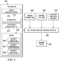
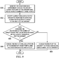
- FIG. 9 an illustration of a flowchart of a process for managing a flight of an aircraft is depicted in accordance with an advantageous embodiment.
- the process illustrated in Figure 9 may be implemented in mission management environment 200 in Figure 2 .
- this process may be implemented using mission management process 212 running on control system 204 in Figure 2 .
- the process begins by monitoring for conditions in an environment around the aircraft during the flight of the aircraft on a route having a number of target points (operation 900).
- the aircraft may perform a number of operations for a mission during the flight of the aircraft.
- the number of operations may be performed at the number of target points along the route.
- the conditions may include at least one of a weather condition, a threat condition, a terrain condition, or some other suitable type of condition.
- the process identifies current resources for the aircraft in response to detecting a condition requiring a change to the route of the aircraft (operation 902).
- Current resources may include a fuel level, engine power, available weapons, and/or other types of resources.
- the condition may be one of a weather condition, a threat condition, a terrain condition, or some other suitable type of condition.
- the process determines whether changing the route reduces the number of target points that can be reached based on the current resources for the aircraft (operation 904). If changing the route reduces the number of target points that can be reached, the process changes the route to include a portion of the number of target points using the condition detected and a policy (operation 906), with the process terminating thereafter. Otherwise, if changing the route does not reduce the number of target points that can be reached, the process changes the route of the aircraft to form a new route using a model of the aircraft (operation 908), with the process terminating thereafter.
- the process illustrated in Figure 9 may be repeated continuously during the flight of the aircraft in this illustrative example. In other illustrative examples, this process may be repeated in response to a periodic event occurring.
- the event may be, for example, the lapse of a selected period of time.
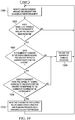
- FIG. 10 an illustration of a flowchart of a process for managing a mission during a flight of an aircraft is depicted in accordance with an advantageous embodiment.
- the process illustrated in Figure 10 may be implemented in mission management environment 200 in Figure 2 .
- this process may be implemented using mission management process 212 running on control system 204 in Figure 2 .
- Operation 1000 begins by monitoring an environment around the aircraft for changes in the environment (operation 1000).
- Operation 1000 is performed using information, such as information 238 in Figure 2 .
- this information may include weather information, a digital elevation model, sensor data, aircraft detectability information, an electronic order of battle, and/or other suitable types of information.
- other types of information about the environment around the aircraft may be used in performing operation 1000.
- the information used to monitor for the conditions in the environment is obtained from systems on-board and/or off-board the aircraft.
- the process determines whether a number of changes in the environment around the aircraft have been detected (operation 1002). In operation 1002, more than one change may be detected at a time. If a number of changes in the environment around the aircraft have not been detected, the process returns to operation 1000 as described above.
- the process determines whether the number of changes in the environment around the aircraft affect a current route for the aircraft (operation 1004). This determination is made by performing a real-time analysis of the number of changes detected and parameters for the number of operations to be performed for a mission of the aircraft. For example, operation 1004 may determine whether the number of changes detected in the environment affect the current route for the mission. As one illustrative example, a thunderstorm detected along the route for the aircraft indicates that the route for the aircraft should be changed.
- the process then records the number of changes detected (operation 1006). Recording the number of changes detected also includes recording a time for when and/or a location for where the number of changes is detected. Then, the process returns to operation 1000 as described above.
- the process determines whether the aircraft has the capability to make changes to the route for the aircraft in response to the number of changes in the environment (operation 1008). This determination is made using a model of the aircraft, such as model 241 in Figure 2 .
- the model may include aircraft performance information and aircraft resource information.
- the process proceeds to operation 1006 as described above. Otherwise, if the aircraft does have the capability to make the changes to the route for the aircraft in response to the number of changes, the process makes the changes to the current route using a route analysis and planning process and a resource allocation process (operation 1010), with the process then returning to operation 1000 as described above.
- the route analysis planning process may be route analysis and planning process 214 in Figure 2 .
- the resource allocation process may be resource allocation process 216 in Figure 2 .
- the new route may be formed using information, such as information 238 in Figure 2 and information 504 in Figure 5 . Further, the new route may be formed using, for example, mission parameters 506, control features 508, and objective functions weights 510 in Figure 5 .
- operation 1010 may use a landing zone process, such as landing zone process 218 in Figure 2 , to make the changes to the route for the aircraft when the number of changes in the environment indicates that the aircraft should land.
- a landing zone process such as landing zone process 218 in Figure 2
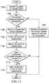
- FIG. 11 an illustration of a flowchart of a process for selecting a landing zone is depicted in accordance with an advantageous embodiment.
- the process illustrated in Figure 11 may be implemented using mission management process 212 running on control system 204 in Figure 2 .
- this process may be implemented using landing zone process 218 in Figure 2 .
- this process may be implemented at different points along the flight path of an aircraft.
- the process begins by identifying a number of landing zones (operation 1100).
- the number of landing zones may be identified using, for example, information 702 in Figure 7 .
- the process determines whether any landing zones in the number of landing zones identified are reachable by the aircraft (operation 1102).
- the process prepares the aircraft for a crash landing and/or detonation of the aircraft (operation 1104), with the process terminating thereafter.
- the aircraft is prepared for the crash landing and/or detonation of the aircraft even if a crash landing is not required at the current point in time.
- the process selects a landing zone for the aircraft (operation 1106).
- a landing zone for the aircraft if only one landing zone is reachable, that landing zone is selected. If more than one landing zone is reachable, the landing zone for the aircraft may be selected based on a number of factors. These factors may include, for example, aero-kinematic performance of the aircraft.
- the process stores the selected landing zone (operation 1108).
- the process dis-plays the selected landing zone (operation 1110).
- the process determines whether a situation has occurred requiring the aircraft to land (operation 1112).
- the process lands the aircraft at the selected landing zone (operation 1114), with the process terminating thereafter. Otherwise, in operation 1112, if a situation has not occurred, the process terminates.
- the process illustrated in Figure 11 may be repeated at every waypoint encountered during flight of the aircraft. In some illustrative examples, this process may be repeated every time a selected distance is passed during flight of the aircraft. For example, the process may be repeated every five miles or every 10 miles during the flight of the aircraft.
- each block in the flowcharts or block diagrams may represent a module, segment, function, and/or a portion of an operation or step.
- the function or functions noted in the block may occur out of the order noted in the figures.
- two blocks shown in succession may be executed substantially concurrently, or the blocks may sometimes be executed in the reverse order, depending upon the functionality involved.
- other blocks may be added in addition to the illustrated blocks in a flowchart or block diagram.
- the different advantageous embodiments can take the form of an entirely hardware embodiment, an entirely software embodiment, or an embodiment containing both hardware and software elements.
- Some embodiments are implemented in software, which includes, but is not limited to, forms, such as, for example, firmware, resident software, and microcode.
- the different embodiments can take the form of a computer program product accessible from a computer usable or computer readable medium providing program code for use by or in connection with a computer or any device or system that executes instructions.
- a computer usable or computer readable medium can generally be any tangible apparatus that can contain, store, communicate, propagate, or transport the program for use by or in connection with the instruction execution system, apparatus, or device.
- the computer usable or computer readable medium can be, for example, without limitation, an electronic, magnetic, optical, electromagnetic, infrared, or semiconductor system, or a propagation medium.
- a computer readable medium include a semiconductor or solid state memory, magnetic tape, a removable computer diskette, a random access memory (RAM), a read-only memory (ROM), a rigid magnetic disk, and an optical disk.
- Optical disks may include compact disk - read only memory (CD-ROM), compact disk - read/write (CD-R/W), and DVD.
- a computer usable or computer readable medium may contain or store a computer readable or usable program code such that when the computer readable or usable program code is executed on a computer, the execution of this computer readable or usable program code causes the computer to transmit another computer readable or usable program code over a communications link.
- This communications link may use a medium that is, for example, without limitation, physical or wireless.
- a data processing system suitable for storing and/or executing computer readable or computer usable program code will include one or more processors coupled directly or indirectly to memory elements through a communications fabric, such as a system bus.
- the memory elements may include local memory employed during actual execution of the program code, bulk storage, and cache memories, which provide temporary storage of at least some computer readable or computer usable program code to reduce the number of times code may be retrieved from bulk storage during execution of the code.
- I/O devices can be coupled to the system either directly or through intervening I/O controllers. These devices may include, for example, without limitation, keyboards, touch screen displays, and pointing devices. Different communications adapters may also be coupled to the system to enable the data processing system to become coupled to other data processing systems, remote printers, or storage devices through intervening private or public networks. Nonlimiting examples are modems and network adapters and are just a few of the currently available types of communications adapters.
Landscapes
- Engineering & Computer Science (AREA)
- Radar, Positioning & Navigation (AREA)
- Remote Sensing (AREA)
- Aviation & Aerospace Engineering (AREA)
- Physics & Mathematics (AREA)
- General Physics & Mathematics (AREA)
- Automation & Control Theory (AREA)
- Business, Economics & Management (AREA)
- Health & Medical Sciences (AREA)
- Artificial Intelligence (AREA)
- Evolutionary Computation (AREA)
- Game Theory and Decision Science (AREA)
- Medical Informatics (AREA)
- Traffic Control Systems (AREA)
- Navigation (AREA)
Claims (14)
- Verfahren zum Verwalten eines Fluges eines Flugzeugs (202), wobei das Flugzeug (202) ein unbemanntes Luftfahrzeug mit einem Steuersystem (204) ist, wobei das Verfahren umfasst:Überwachen (900), durch das Steuersystem (204), auf Bedingungen in einer Umgebung um das Flugzeug herum während des Fluges des Flugzeugs auf einer Route (220) mit einer Anzahl von Wegpunkten (242) und mit einer Anzahl von Zielpunkten, wobei die Zielpunkte (244) Punkte aus der Anzahl von Wegpunkten (242) entlang der Route (220) sind, an denen das Flugzeug (202) eine Anzahl von Operationen ausführt, wobei jeder Zielpunkt ein Punkt ist, an dem das Flugzeug (202) Überwachungsinformationen sammelt, Sensorinformationen erzeugt, eine Waffe einsetzt oder ein Ziel angreift;Identifizieren aktueller Ressourcen für das Flugzeug durch das Steuersystem (204) als Reaktion (902) auf das Erfassen einer Bedingung, die eine Änderung der Route des Flugzeugs erfordert;gekennzeichnet durch:Bestimmen (904), durch das Steuersystem (204), ob das Ändern der Route die Anzahl der Zielpunkte reduziert, die basierend auf den aktuellen Ressourcen für das Flugzeug erreicht werden können; undin Reaktion auf ein Bestimmen, dass das Ändern (906) der Route die Anzahl der erreichbaren Zielpunkte (812, 813) reduziert, Ändern der Route durch das Steuersystem (204) unter Verwendung der Bedingung und einer Richtlinie, so dass sie einen Teil der Anzahl der Zielpunkte beinhaltet.
- Verfahren nach Anspruch 1, ferner umfassend:
in Reaktion auf ein Fehlen des Bestimmens, dass das Ändern der Route (908) die Anzahl der erreichbaren Zielpunkte reduziert, Ändern der Route des Flugzeugs (202) durch das Steuersystem (204), um eine neue Route zu bilden, unter Verwendung eines Modells (518) des Flugzeugs. - Verfahren nach Anspruch 1, ferner umfassend:Bestimmen, durch das Steuersystem (204), ob ein Ziel-Wegpunkt auf der Route von dem Flugzeug (202) mit den aktuellen Ressourcen für das Flugzeug erreicht werden kann;
undin Reaktion auf ein Bestimmen, dass der Ziel-Wegpunkt auf der Route mit den aktuellen Ressourcen für das Flugzeug nicht erreicht werden kann, Auswählen (1106) einer Landezone für das Flugzeug durch das Steuersystem (204). - Verfahren nach Anspruch 3, wobei der Schritt des Auswählens der Landezone für das Flugzeug in Reaktion auf das Bestimmen, dass der Ziel-Wegpunkt in der Route mit den aktuellen Ressourcen für das Flugzeug (202) nicht erreicht werden kann, umfasst:
Identifizieren (1100) von Informationen über eine Anzahl von erreichbaren Landeplätzen für das Flugzeug basierend auf Anforderungen für eine gewünschte Landezone durch das Steuersystem (204). - Verfahren nach Anspruch 1, bei dem der Schritt des Ändern der Route unter Verwendung der Bedingung und der Richtlinie, so dass sie einen Teil der Anzahl der Zielpunkte beinhaltet, in Reaktion auf ein Bestimmen, dass das Ändern (906) der Route die Anzahl der erreichbaren Zielpunkte reduziert, umfasst:Auswählen des Teils der Anzahl der Zielpunkte (812, 813) unter Verwendung der Bedingung und der Richtlinie durch das Steuersystem (204); undErzeugen einer neuen Route von einer aktuellen Position des Flugzeugs zu der Anzahl der Zielpunkte durch das Steuersystem (204).
- Verfahren nach Anspruch 5, bei dem der Schritt des Erzeugens der neuen Route von der aktuellen Position des Flugzeugs (202) zu der Anzahl der Zielpunkte umfasst:Auswählen einer Reihenfolge für den Teil der Anzahl der Zielpunkte (812, 813) durch das Steuersystem (204); undErzeugen der neuen Route von der aktuellen Position des Flugzeugs zu der Anzahl der Zielpunkte unter Verwendung der Bedingung, der Richtlinie, der aktuellen Ressourcen für das Flugzeug und eines Modells des Flugzeugs durch das Steuersystem (204).
- Verfahren nach Anspruch 1, bei dem die Richtlinie die Verwendung einer zweiten Route vorsieht, die eine Höhe und einen Verlauf durch Terrain aufweist, die das Erfassen des Flugzeugs (202) reduzieren.
- Verfahren nach Anspruch 1, bei dem der Schritt des Überwachens (900) der Bedingungen in der Umgebung um das Flugzeug (202) herum während des Fluges des Flugzeugs auf der Route mit der Anzahl von Zielpunkten umfasst:
Überwachen der Bedingungen in der Umgebung um das Flugzeug herum durch das Steuersystem (204) während des Fluges des Flugzeugs auf der Route mit der Anzahl von Zielpunkten unter Verwendung eines dem Flugzeug zugeordneten Sensorsystems. - Verfahren nach Anspruch 1, bei dem die Bedingung ausgewählt ist unter einer Bedrohung für das Flugzeug (202), einer Umweltbedingung und einer Wetterbedingung.
- Vorrichtung, umfassend:ein Flugzeug (202); undein dem Flugzeug zugeordnetes Steuersystem (204), wobei das Steuersystem konfiguriert ist, um während des Fluges des Flugzeugs auf einer Route (220) mit einer Anzahl von Wegpunkten (242) und mit einer Anzahl von Zielpunkten, wobei die Zielpunkte (244) Punkte aus der Anzahl von Wegpunkten (242) entlang der Route (220) sind, an denen das Flugzeug (202) eine Anzahl von Operationen ausführt, wobei jeder Zielpunkt ein Punkt ist, an dem das Flugzeug (202) Überwachungsinformationen sammelt, Sensorinformationen erzeugt, eine Waffe einsetzt oder ein Ziel angreift,in Reaktion auf das Erfassen eines Zustands, der eine Änderung der Route des Flugzeugs erfordert, aktuelle Ressourcen für das Flugzeug zu identifizieren;wobei das Flugzeug (202) ein unbemanntes Luftfahrzeug ist;
unddadurch gekennzeichnet, dass das Steuersystem ferner konfiguriert ist, um:
zu bestimmen (904), ob das Ändern der Route die Anzahl der Zielpunkte reduziert, die basierend auf den aktuellen Ressourcen für das Flugzeug erreicht werden können; und in Reaktion auf ein Bestimmen, dass das Ändern der Route die Anzahl der Zielpunkte reduziert, die erreicht werden können, die Route unter Verwendung der Bedingung und einer Richtlinie so zu ändern (906), dass sie einen Teil der Anzahl der Zielpunkte beinhaltet. - Vorrichtung nach Anspruch 10, bei der das Steuersystem (204) ferner konfiguriert ist, um in Reaktion auf ein Fehlen des Bestimmens, dass das Ändern der Route die Anzahl der erreichbaren Zielpunkte reduziert, unter Verwendung eines Modells des Flugzeugs die Route des Flugzeugs (202) zu ändern (908), um eine neue Route zu bilden.
- Vorrichtung nach Anspruch 10, bei der das Steuersystem (204) ferner konfiguriert ist, um zu bestimmen, ob ein Ziel-Wegpunkt auf der Route von dem Flugzeug (202) mit den aktuellen Ressourcen für das Flugzeug erreicht werden kann; und in Reaktion auf ein Bestimmen, dass der Ziel-Wegpunkt auf der Route mit den aktuellen Ressourcen für das Flugzeug nicht erreicht werden kann, eine Landezone für das Flugzeug auszuwählen.
- Vorrichtung nach Anspruch 10, bei der das Steuersystem (204) konfiguriert ist, um beim Ändern der Route unter Verwendung der Bedingung und der Richtlinie, so dass sie einen Teil der Anzahl der Zielpunkte beinhaltet, in Reaktion auf ein Bestimmen, dass das Ändern (906) der Route die Anzahl der erreichbaren Zielpunkte reduziert,den Teil der Anzahl der Zielpunkte unter Verwendung der Bedingung und der Richtlinie auszuwählen; undeine neue Route von einem aktuellen Standort des Flugzeugs zu der Anzahl der Zielpunkte zu erzeugen.
- Vorrichtung nach Anspruch 10, ferner umfassend:
ein dem Flugzeug (202) zugeordnetes Sensorsystem, wobei das Sensorsystem konfiguriert ist, um Informationen zu erzeugen, die von dem Steuersystem verwendet werden, um die Bedingungen in der Umgebung um das Flugzeug herum während des Fluges des Flugzeugs auf der Route mit der Anzahl der Zielpunkte zu überwachen.
Priority Applications (1)
| Application Number | Priority Date | Filing Date | Title |
|---|---|---|---|
| EP19152985.8A EP3505871B1 (de) | 2010-09-14 | 2011-09-13 | Verwaltungssystem für unbemannte luftfahrzeuge |
Applications Claiming Priority (1)
| Application Number | Priority Date | Filing Date | Title |
|---|---|---|---|
| US12/881,292 US8594932B2 (en) | 2010-09-14 | 2010-09-14 | Management system for unmanned aerial vehicles |
Related Child Applications (2)
| Application Number | Title | Priority Date | Filing Date |
|---|---|---|---|
| EP19152985.8A Division EP3505871B1 (de) | 2010-09-14 | 2011-09-13 | Verwaltungssystem für unbemannte luftfahrzeuge |
| EP19152985.8A Division-Into EP3505871B1 (de) | 2010-09-14 | 2011-09-13 | Verwaltungssystem für unbemannte luftfahrzeuge |
Publications (4)
| Publication Number | Publication Date |
|---|---|
| EP2498055A2 EP2498055A2 (de) | 2012-09-12 |
| EP2498055A3 EP2498055A3 (de) | 2016-09-14 |
| EP2498055B1 EP2498055B1 (de) | 2019-01-23 |
| EP2498055B2 true EP2498055B2 (de) | 2022-01-05 |
Family
ID=44675501
Family Applications (2)
| Application Number | Title | Priority Date | Filing Date |
|---|---|---|---|
| EP11181017.2A Active EP2498055B2 (de) | 2010-09-14 | 2011-09-13 | Verwaltungssystem für unbemannte Luftfahrzeuge |
| EP19152985.8A Active EP3505871B1 (de) | 2010-09-14 | 2011-09-13 | Verwaltungssystem für unbemannte luftfahrzeuge |
Family Applications After (1)
| Application Number | Title | Priority Date | Filing Date |
|---|---|---|---|
| EP19152985.8A Active EP3505871B1 (de) | 2010-09-14 | 2011-09-13 | Verwaltungssystem für unbemannte luftfahrzeuge |
Country Status (3)
| Country | Link |
|---|---|
| US (1) | US8594932B2 (de) |
| EP (2) | EP2498055B2 (de) |
| ES (1) | ES2720879T5 (de) |
Families Citing this family (47)
| Publication number | Priority date | Publication date | Assignee | Title |
|---|---|---|---|---|
| FR2958033B1 (fr) * | 2010-03-24 | 2012-05-25 | Dassault Aviat | Dispositif d'affichage de la variation d'energie d'un aeronef, procede et systeme d'affichage de la variation d'energie correspondants |
| US20120029720A1 (en) * | 2010-07-29 | 2012-02-02 | Spirae, Inc. | Dynamic distributed power grid control system |
| US8594932B2 (en) | 2010-09-14 | 2013-11-26 | The Boeing Company | Management system for unmanned aerial vehicles |
| US8818712B2 (en) * | 2011-03-28 | 2014-08-26 | Raytheon Company | Maritime path determination |
| US20130179011A1 (en) * | 2012-01-10 | 2013-07-11 | Lockheed Martin Corporation | Emergency landing zone recognition |
| CN102749080B (zh) * | 2012-06-18 | 2015-01-07 | 北京航空航天大学 | 一种基于流体力学的无人机三维航路生成方法 |
| IL221263A (en) * | 2012-08-02 | 2017-08-31 | Israel Aerospace Ind Ltd | Unmanned aerial vehicles |
| US9443207B2 (en) * | 2012-10-22 | 2016-09-13 | The Boeing Company | Water area management system |
| CN103885452B (zh) * | 2012-12-21 | 2016-09-07 | 中国直升机设计研究所 | 一种无人直升机地面控制终端设备 |
| EP2781980B2 (de) * | 2013-03-19 | 2021-12-08 | The Boeing Company | Verfahren zum Fliegen eines unbemannten Luftfahrzeugs |
| US9417070B1 (en) * | 2013-04-01 | 2016-08-16 | Nextgen Aerosciences, Inc. | Systems and methods for continuous replanning of vehicle trajectories |
| US9676472B2 (en) * | 2013-08-30 | 2017-06-13 | Insitu, Inc. | Systems and methods for configurable user interfaces |
| US9824596B2 (en) * | 2013-08-30 | 2017-11-21 | Insitu, Inc. | Unmanned vehicle searches |
| US10402766B1 (en) * | 2013-11-08 | 2019-09-03 | The Boeing Company | Systems, methods, and apparatus for operations simulation, visualization, and improvement |
| US9557742B2 (en) | 2013-11-27 | 2017-01-31 | Aurora Flight Sciences Corporation | Autonomous cargo delivery system |
| CN103713642B (zh) * | 2013-12-24 | 2016-05-04 | 北京航空航天大学 | 一种基于扰动流体动态系统的无人机三维航路规划方法 |
| US9562773B2 (en) | 2014-03-15 | 2017-02-07 | Aurora Flight Sciences Corporation | Autonomous vehicle navigation system and method |
| US9881022B2 (en) * | 2014-05-20 | 2018-01-30 | Verizon Patent And Licensing Inc. | Selection of networks for communicating with unmanned aerial vehicles |
| US9671790B2 (en) * | 2014-05-20 | 2017-06-06 | Verizon Patent And Licensing Inc. | Scheduling of unmanned aerial vehicles for mission performance |
| US9547990B2 (en) | 2014-08-21 | 2017-01-17 | Honeywell International Inc. | Rotary-wing aircraft emergency landing control |
| WO2016048743A1 (en) | 2014-09-22 | 2016-03-31 | Sikorsky Aircraft Corporation | Context-based autonomous perception |
| WO2016109000A2 (en) | 2014-10-20 | 2016-07-07 | Sikorsky Aircraft Corporation | Optimal safe landing area determination |
| IL235502B (en) | 2014-11-05 | 2020-02-27 | Elta Systems Ltd | Systems for and methods of providing indicators useful for piloting an aircraft |
| EP3286079B1 (de) | 2015-04-21 | 2021-09-08 | GoPro, Inc. | Lufterfassungsplattform |
| US10696414B2 (en) | 2015-04-21 | 2020-06-30 | Gopro, Inc. | Aerial capture platform |
| US12221237B2 (en) | 2015-04-21 | 2025-02-11 | Gopro, Inc. | Unmanned aerial vehicle with rotating and overlapping rotor arms |
| JP2017058829A (ja) * | 2015-09-15 | 2017-03-23 | 株式会社オプティム | 無人航空機制御システム、無人航空機制御方法 |
| CN108351653B (zh) * | 2015-12-09 | 2022-08-09 | 深圳市大疆创新科技有限公司 | 用于uav飞行控制的系统和方法 |
| IL245277B (en) | 2016-04-20 | 2019-11-28 | Elta Systems Ltd | Dynamic link-budget monitoring and graphical display |
| CN107636551B (zh) * | 2016-09-22 | 2021-11-30 | 深圳市大疆创新科技有限公司 | 一种飞行控制方法、装置及智能终端 |
| US9977432B1 (en) * | 2016-12-22 | 2018-05-22 | Kitty Hawk Corporation | Distributed flight control system |
| US10599138B2 (en) | 2017-09-08 | 2020-03-24 | Aurora Flight Sciences Corporation | Autonomous package delivery system |
| US10426393B2 (en) | 2017-09-22 | 2019-10-01 | Aurora Flight Sciences Corporation | Systems and methods for monitoring pilot health |
| CN109405830B (zh) * | 2018-09-04 | 2021-09-21 | 西安爱生无人机技术有限公司 | 基于线路坐标序列的无人机自动巡检方法 |
| US11136120B2 (en) | 2018-10-05 | 2021-10-05 | Aurora Flight Sciences Corporation | Ground operations for autonomous object pickup |
| US11037453B2 (en) | 2018-10-12 | 2021-06-15 | Aurora Flight Sciences Corporation | Adaptive sense and avoid system |
| US10984664B2 (en) | 2018-12-13 | 2021-04-20 | The Boeing Company | System for determining potential landing sites for aircraft prior to landing assist device deployment |
| EP3908999A4 (de) * | 2019-01-10 | 2022-10-19 | Nokia Technologies Oy | Verfahren und vorrichtung zur sicheren lieferung von ladung |
| KR102759404B1 (ko) * | 2019-09-11 | 2025-01-24 | 한화에어로스페이스 주식회사 | 위험맵에 위험 예측도를 반영하여 객체들의 주행 경로를 재생성하는 방법 및 원격통제장치 |
| US12282339B2 (en) * | 2019-10-09 | 2025-04-22 | Rakuten Group, Inc. | Processing system, unmanned aerial vehicle, and flight route designation method |
| CN111766901B (zh) * | 2020-07-22 | 2022-10-04 | 哈尔滨工程大学 | 多无人机协同目标分配攻击方法 |
| US11756434B2 (en) * | 2020-11-30 | 2023-09-12 | Bae Systems Information And Electronic Systems Integration Inc. | System and method for non-navigation data in platform routing |
| CN116710943A (zh) * | 2021-03-17 | 2023-09-05 | 深圳市大疆创新科技有限公司 | 无人机调度方法、服务器、基站、系统及可读存储介质 |
| WO2022205294A1 (zh) * | 2021-04-01 | 2022-10-06 | 深圳市大疆创新科技有限公司 | 无人机的控制方法、装置、无人机及存储介质 |
| CN113359853B (zh) * | 2021-07-09 | 2022-07-19 | 中国人民解放军国防科技大学 | 一种无人机编队协同目标监视的路径规划方法及系统 |
| US11435761B1 (en) | 2021-07-23 | 2022-09-06 | Beta Air, Llc | System and method for distributed flight control system for an electric vehicle |
| TWI909185B (zh) * | 2023-08-02 | 2025-12-21 | 緯創資通股份有限公司 | 飛行器飛航路線規劃方法、裝置及非暫時性電腦可讀儲存媒體 |
Citations (20)
| Publication number | Priority date | Publication date | Assignee | Title |
|---|---|---|---|---|
| US4642775A (en) † | 1984-05-25 | 1987-02-10 | Sundstrand Data Control, Inc. | Airborne flight planning and information system |
| EP0427431A2 (de) † | 1989-11-08 | 1991-05-15 | Smiths Industries Public Limited Company | Navigationssysteme |
| US6377875B1 (en) † | 1998-10-29 | 2002-04-23 | Daimlerchrysler Ag | Method for remote-controlling an unmanned aerial vehicle |
| AU751278B2 (en) † | 1999-04-08 | 2002-08-08 | Honeywell International, Inc. | Midair collision avoidance system |
| EP1462898A2 (de) † | 2003-03-27 | 2004-09-29 | Saab Ab | Auf Landmarken basierende Navigation |
| EP1612632A1 (de) † | 2004-07-03 | 2006-01-04 | Saab Ab | System und Verfahren zur Steuerung eines Flugzeugs während des Fluges |
| US20060106506A1 (en) † | 2004-11-16 | 2006-05-18 | Nichols William M | Automatic contingency generator |
| US20060167599A1 (en) † | 2005-01-24 | 2006-07-27 | Bodin William K | Identifying a UAV landing location |
| US20060235581A1 (en) † | 2003-04-16 | 2006-10-19 | Jean-Paul Petillon | Secure interactive 3d navigation method and device |
| US20070129855A1 (en) † | 2005-12-07 | 2007-06-07 | Thales | Device and method of automated construction of emergency flight path for aircraft |
| US20080147309A1 (en) † | 2006-06-30 | 2008-06-19 | Saab Ab | Termination secured route planning |
| US20080154447A1 (en) † | 2006-12-21 | 2008-06-26 | Spinelli Charles B | Determining suitable areas for off-airport landings |
| US20080167763A1 (en) † | 2006-04-20 | 2008-07-10 | Saab Ab | Emergency flight plan |
| EP2017808A2 (de) † | 2007-06-14 | 2009-01-21 | The Boeing Company | Automatische Funktion für strategische Offsets |
| EP2050671A1 (de) † | 2007-10-17 | 2009-04-22 | The Boeing Company | Flugzeug mit sich verändernder Besetzung |
| US20090125163A1 (en) † | 2003-06-20 | 2009-05-14 | Geneva Aerospace | Vehicle control system including related methods and components |
| US20090171560A1 (en) † | 2008-01-02 | 2009-07-02 | Mcferran Nancy L | Prioritizing alternative landing facilities in flight planning |
| US20090265049A1 (en) † | 2008-04-22 | 2009-10-22 | Honeywell International, Inc. | Aircraft system emissions and noise estimation mechanism |
| US7702427B1 (en) † | 2004-07-30 | 2010-04-20 | The United States Of America As Represented By The National Aeronautics And Space Administration (Nasa) | Air traffic management evaluation tool |
| WO2011152917A2 (en) † | 2010-04-21 | 2011-12-08 | The Boeing Company | Determining landing sites for aircraft |
Family Cites Families (9)
| Publication number | Priority date | Publication date | Assignee | Title |
|---|---|---|---|---|
| US5838262A (en) * | 1996-12-19 | 1998-11-17 | Sikorsky Aircraft Corporation | Aircraft virtual image display system and method for providing a real-time perspective threat coverage display |
| US7693120B2 (en) * | 2006-06-26 | 2010-04-06 | The Boeing Company | Neural network-based mobility management for self-partition detection and identification of mobile ad hoc radio networks |
| US7742425B2 (en) * | 2006-06-26 | 2010-06-22 | The Boeing Company | Neural network-based mobility management for mobile ad hoc radio networks |
| US7555468B2 (en) * | 2006-06-26 | 2009-06-30 | The Boeing Company | Neural network-based node mobility and network connectivty predictions for mobile ad hoc radio networks |
| US7848262B2 (en) * | 2006-06-26 | 2010-12-07 | The Boeing Company | Neural network-based mobility management for healing mobile ad hoc radio networks |
| FR2907952B1 (fr) * | 2006-10-26 | 2008-12-19 | Airbus France Sa | Procede et dispositif d'aide au guidage d'un aeronef le long d'une trajectoire de vol. |
| US7860646B2 (en) | 2007-04-16 | 2010-12-28 | The Boeing Company | Method and apparatus for routing ocean going vessels to avoid treacherous environments |
| US8140252B2 (en) * | 2008-12-09 | 2012-03-20 | Honeywell International Inc. | System and method for displaying protected airspace associated with a projected trajectory of aircraft in a confidence display |
| US8594932B2 (en) | 2010-09-14 | 2013-11-26 | The Boeing Company | Management system for unmanned aerial vehicles |
-
2010
- 2010-09-14 US US12/881,292 patent/US8594932B2/en active Active
-
2011
- 2011-09-13 ES ES11181017T patent/ES2720879T5/es active Active
- 2011-09-13 EP EP11181017.2A patent/EP2498055B2/de active Active
- 2011-09-13 EP EP19152985.8A patent/EP3505871B1/de active Active
Patent Citations (20)
| Publication number | Priority date | Publication date | Assignee | Title |
|---|---|---|---|---|
| US4642775A (en) † | 1984-05-25 | 1987-02-10 | Sundstrand Data Control, Inc. | Airborne flight planning and information system |
| EP0427431A2 (de) † | 1989-11-08 | 1991-05-15 | Smiths Industries Public Limited Company | Navigationssysteme |
| US6377875B1 (en) † | 1998-10-29 | 2002-04-23 | Daimlerchrysler Ag | Method for remote-controlling an unmanned aerial vehicle |
| AU751278B2 (en) † | 1999-04-08 | 2002-08-08 | Honeywell International, Inc. | Midair collision avoidance system |
| EP1462898A2 (de) † | 2003-03-27 | 2004-09-29 | Saab Ab | Auf Landmarken basierende Navigation |
| US20060235581A1 (en) † | 2003-04-16 | 2006-10-19 | Jean-Paul Petillon | Secure interactive 3d navigation method and device |
| US20090125163A1 (en) † | 2003-06-20 | 2009-05-14 | Geneva Aerospace | Vehicle control system including related methods and components |
| EP1612632A1 (de) † | 2004-07-03 | 2006-01-04 | Saab Ab | System und Verfahren zur Steuerung eines Flugzeugs während des Fluges |
| US7702427B1 (en) † | 2004-07-30 | 2010-04-20 | The United States Of America As Represented By The National Aeronautics And Space Administration (Nasa) | Air traffic management evaluation tool |
| US20060106506A1 (en) † | 2004-11-16 | 2006-05-18 | Nichols William M | Automatic contingency generator |
| US20060167599A1 (en) † | 2005-01-24 | 2006-07-27 | Bodin William K | Identifying a UAV landing location |
| US20070129855A1 (en) † | 2005-12-07 | 2007-06-07 | Thales | Device and method of automated construction of emergency flight path for aircraft |
| US20080167763A1 (en) † | 2006-04-20 | 2008-07-10 | Saab Ab | Emergency flight plan |
| US20080147309A1 (en) † | 2006-06-30 | 2008-06-19 | Saab Ab | Termination secured route planning |
| US20080154447A1 (en) † | 2006-12-21 | 2008-06-26 | Spinelli Charles B | Determining suitable areas for off-airport landings |
| EP2017808A2 (de) † | 2007-06-14 | 2009-01-21 | The Boeing Company | Automatische Funktion für strategische Offsets |
| EP2050671A1 (de) † | 2007-10-17 | 2009-04-22 | The Boeing Company | Flugzeug mit sich verändernder Besetzung |
| US20090171560A1 (en) † | 2008-01-02 | 2009-07-02 | Mcferran Nancy L | Prioritizing alternative landing facilities in flight planning |
| US20090265049A1 (en) † | 2008-04-22 | 2009-10-22 | Honeywell International, Inc. | Aircraft system emissions and noise estimation mechanism |
| WO2011152917A2 (en) † | 2010-04-21 | 2011-12-08 | The Boeing Company | Determining landing sites for aircraft |
Non-Patent Citations (5)
| Title |
|---|
| ANONYMOUS: "Informationen aus dem Bereich Forschung und Entwicklung der DFS Deutsche Flugsicherung GmbH", DFS DEUTSCHE FLUGSICHERUNG GMBH, 12 December 2007 (2007-12-12), pages 1 - 38 † |
| BERND KORN ET AL.: ""File and fly" - Procedures and Techniques for Integration of UAVs in Controlled Airspace", 25TH INTERNATIONAL CONGRESS OF THE AERONAUTICAL SCIENCES, 2006, pages 1 - 8 † |
| ELLA M ATKINS; EDMUND H DURFEE; KANG G SHIN: "Autonomous Flight with CIRCA-II", April 2001 (2001-04-01), pages 1 - 7 † |
| H. DORGELOH ET AL.: "Führungssysteme für unbemannte Luftfahrzeuge", DLR-BRAUNSCHWEIG, 2009, pages 1 - 46 † |
| https://www.nsf.gov/awardsearch/showAward?AWD_ID=9209031 † |
Also Published As
| Publication number | Publication date |
|---|---|
| EP2498055B1 (de) | 2019-01-23 |
| EP2498055A3 (de) | 2016-09-14 |
| ES2720879T5 (es) | 2022-05-06 |
| EP3505871A1 (de) | 2019-07-03 |
| US20120065881A1 (en) | 2012-03-15 |
| US8594932B2 (en) | 2013-11-26 |
| ES2720879T3 (es) | 2019-07-25 |
| EP2498055A2 (de) | 2012-09-12 |
| EP3505871B1 (de) | 2021-12-22 |
Similar Documents
| Publication | Publication Date | Title |
|---|---|---|
| EP2498055B2 (de) | Verwaltungssystem für unbemannte Luftfahrzeuge | |
| CN106249750B (zh) | 在无人驾驶飞行器上自主执行决策以完成任务的方法和装置 | |
| CN104797995B (zh) | 在发生飞行偶然事件的情况下无人飞行器飞行路径的确定 | |
| US8843303B1 (en) | Risk-aware contingency flight re-planner system and related method | |
| US10474144B2 (en) | Remote information collection, situational awareness, and adaptive response system for improving advance threat awareness and hazardous risk avoidance | |
| KR102026485B1 (ko) | 예측불가능 운송수단 내비게이션 | |
| US10281281B2 (en) | Decision support and control systems including various graphical user interfaces configured for displaying multiple transit options for a platform with respect to hazard and objects and related methods | |
| Rabinovich et al. | Toward dynamic monitoring and suppressing uncertainty in wildfire by multiple unmanned air vehicle system | |
| US9014958B2 (en) | Control apparatus, display apparatus, cooperative operation system, and control method | |
| US20210072755A1 (en) | Method and remote control device for reconfiguring travel route of objects by reflecting predicted risk level to risk map | |
| EP4012340B1 (de) | Expositionszeitbasierte kostenfunktion für routenplanung | |
| Theunissen et al. | Integration of threat information into the route (re-) planning task | |
| US12087171B2 (en) | Assurance module | |
| Vozella et al. | Solution Set Up for Airport Protection from Intruder Drones | |
| Vetrella et al. | Requirements, platform specifications, and system architectures for future unmanned traffic management systems | |
| Nohel et al. | The Requirements of Commanders on Ground Control Station of Heterogenous Swarm Robotic Systems | |
| Khreish | A systems approach to Vertical Take-off Unmanned Aerial Vehicle design for interoperability | |
| Williams | Feasibility of an extended-duration aerial platform using autonomous multi-rotor vehicle swapping and battery management | |
| WO2025114691A1 (en) | Air/space object deconflication tool for laser directed energy weapons | |
| Moreland et al. | Hunter standoff killer team (HSKT) ground and flight test results | |
| WO2022176892A1 (ja) | 飛翔体対処システム、監視地上センター、対処地上センター、通信ルート探索装置、飛翔経路予測装置及び対処アセット選択装置 | |
| Mou et al. | Design of multi-source and multi-dimension information fusion of avionics system | |
| Washburn et al. | Unmanned aerial vehicles | |
| Chang | Exploring C4ISR employment methods | |
| MEDVEDIEV et al. | GORDIENKO OA, researcher TO THE ISSUE OF MODERNIZATION OF AIRBORNE EQUIPMENT OF TACTICAL BOMBERS |
Legal Events
| Date | Code | Title | Description |
|---|---|---|---|
| PUAI | Public reference made under article 153(3) epc to a published international application that has entered the european phase |
Free format text: ORIGINAL CODE: 0009012 |
|
| 17P | Request for examination filed |
Effective date: 20110913 |
|
| AK | Designated contracting states |
Kind code of ref document: A2 Designated state(s): AL AT BE BG CH CY CZ DE DK EE ES FI FR GB GR HR HU IE IS IT LI LT LU LV MC MK MT NL NO PL PT RO RS SE SI SK SM TR |
|
| AX | Request for extension of the european patent |
Extension state: BA ME |
|
| REG | Reference to a national code |
Ref country code: DE Ref legal event code: R079 Ref document number: 602011055871 Country of ref document: DE Free format text: PREVIOUS MAIN CLASS: G01C0021000000 Ipc: G01C0023000000 |
|
| PUAL | Search report despatched |
Free format text: ORIGINAL CODE: 0009013 |
|
| AK | Designated contracting states |
Kind code of ref document: A3 Designated state(s): AL AT BE BG CH CY CZ DE DK EE ES FI FR GB GR HR HU IE IS IT LI LT LU LV MC MK MT NL NO PL PT RO RS SE SI SK SM TR |
|
| AX | Request for extension of the european patent |
Extension state: BA ME |
|
| RIC1 | Information provided on ipc code assigned before grant |
Ipc: G01C 23/00 20060101AFI20160809BHEP Ipc: G05D 1/10 20060101ALI20160809BHEP Ipc: G05D 1/00 20060101ALI20160809BHEP |
|
| GRAP | Despatch of communication of intention to grant a patent |
Free format text: ORIGINAL CODE: EPIDOSNIGR1 |
|
| STAA | Information on the status of an ep patent application or granted ep patent |
Free format text: STATUS: GRANT OF PATENT IS INTENDED |
|
| INTG | Intention to grant announced |
Effective date: 20180803 |
|
| GRAS | Grant fee paid |
Free format text: ORIGINAL CODE: EPIDOSNIGR3 |
|
| GRAA | (expected) grant |
Free format text: ORIGINAL CODE: 0009210 |
|
| STAA | Information on the status of an ep patent application or granted ep patent |
Free format text: STATUS: THE PATENT HAS BEEN GRANTED |
|
| AK | Designated contracting states |
Kind code of ref document: B1 Designated state(s): AL AT BE BG CH CY CZ DE DK EE ES FI FR GB GR HR HU IE IS IT LI LT LU LV MC MK MT NL NO PL PT RO RS SE SI SK SM TR |
|
| REG | Reference to a national code |
Ref country code: GB Ref legal event code: FG4D |
|
| REG | Reference to a national code |
Ref country code: CH Ref legal event code: EP |
|
| REG | Reference to a national code |
Ref country code: AT Ref legal event code: REF Ref document number: 1091802 Country of ref document: AT Kind code of ref document: T Effective date: 20190215 |
|
| REG | Reference to a national code |
Ref country code: IE Ref legal event code: FG4D |
|
| REG | Reference to a national code |
Ref country code: DE Ref legal event code: R096 Ref document number: 602011055871 Country of ref document: DE |
|
| REG | Reference to a national code |
Ref country code: NL Ref legal event code: MP Effective date: 20190123 |
|
| PG25 | Lapsed in a contracting state [announced via postgrant information from national office to epo] |
Ref country code: NL Free format text: LAPSE BECAUSE OF FAILURE TO SUBMIT A TRANSLATION OF THE DESCRIPTION OR TO PAY THE FEE WITHIN THE PRESCRIBED TIME-LIMIT Effective date: 20190123 |
|
| REG | Reference to a national code |
Ref country code: ES Ref legal event code: FG2A Ref document number: 2720879 Country of ref document: ES Kind code of ref document: T3 Effective date: 20190725 |
|
| PG25 | Lapsed in a contracting state [announced via postgrant information from national office to epo] |
Ref country code: PT Free format text: LAPSE BECAUSE OF FAILURE TO SUBMIT A TRANSLATION OF THE DESCRIPTION OR TO PAY THE FEE WITHIN THE PRESCRIBED TIME-LIMIT Effective date: 20190523 Ref country code: SE Free format text: LAPSE BECAUSE OF FAILURE TO SUBMIT A TRANSLATION OF THE DESCRIPTION OR TO PAY THE FEE WITHIN THE PRESCRIBED TIME-LIMIT Effective date: 20190123 Ref country code: FI Free format text: LAPSE BECAUSE OF FAILURE TO SUBMIT A TRANSLATION OF THE DESCRIPTION OR TO PAY THE FEE WITHIN THE PRESCRIBED TIME-LIMIT Effective date: 20190123 Ref country code: PL Free format text: LAPSE BECAUSE OF FAILURE TO SUBMIT A TRANSLATION OF THE DESCRIPTION OR TO PAY THE FEE WITHIN THE PRESCRIBED TIME-LIMIT Effective date: 20190123 Ref country code: NO Free format text: LAPSE BECAUSE OF FAILURE TO SUBMIT A TRANSLATION OF THE DESCRIPTION OR TO PAY THE FEE WITHIN THE PRESCRIBED TIME-LIMIT Effective date: 20190423 Ref country code: LT Free format text: LAPSE BECAUSE OF FAILURE TO SUBMIT A TRANSLATION OF THE DESCRIPTION OR TO PAY THE FEE WITHIN THE PRESCRIBED TIME-LIMIT Effective date: 20190123 |
|
| REG | Reference to a national code |
Ref country code: AT Ref legal event code: MK05 Ref document number: 1091802 Country of ref document: AT Kind code of ref document: T Effective date: 20190123 |
|
| PG25 | Lapsed in a contracting state [announced via postgrant information from national office to epo] |
Ref country code: GR Free format text: LAPSE BECAUSE OF FAILURE TO SUBMIT A TRANSLATION OF THE DESCRIPTION OR TO PAY THE FEE WITHIN THE PRESCRIBED TIME-LIMIT Effective date: 20190424 Ref country code: HR Free format text: LAPSE BECAUSE OF FAILURE TO SUBMIT A TRANSLATION OF THE DESCRIPTION OR TO PAY THE FEE WITHIN THE PRESCRIBED TIME-LIMIT Effective date: 20190123 Ref country code: LV Free format text: LAPSE BECAUSE OF FAILURE TO SUBMIT A TRANSLATION OF THE DESCRIPTION OR TO PAY THE FEE WITHIN THE PRESCRIBED TIME-LIMIT Effective date: 20190123 Ref country code: IS Free format text: LAPSE BECAUSE OF FAILURE TO SUBMIT A TRANSLATION OF THE DESCRIPTION OR TO PAY THE FEE WITHIN THE PRESCRIBED TIME-LIMIT Effective date: 20190523 Ref country code: BG Free format text: LAPSE BECAUSE OF FAILURE TO SUBMIT A TRANSLATION OF THE DESCRIPTION OR TO PAY THE FEE WITHIN THE PRESCRIBED TIME-LIMIT Effective date: 20190423 Ref country code: RS Free format text: LAPSE BECAUSE OF FAILURE TO SUBMIT A TRANSLATION OF THE DESCRIPTION OR TO PAY THE FEE WITHIN THE PRESCRIBED TIME-LIMIT Effective date: 20190123 |
|
| REG | Reference to a national code |
Ref country code: DE Ref legal event code: R026 Ref document number: 602011055871 Country of ref document: DE |
|
| PLBI | Opposition filed |
Free format text: ORIGINAL CODE: 0009260 |
|
| PG25 | Lapsed in a contracting state [announced via postgrant information from national office to epo] |
Ref country code: SK Free format text: LAPSE BECAUSE OF FAILURE TO SUBMIT A TRANSLATION OF THE DESCRIPTION OR TO PAY THE FEE WITHIN THE PRESCRIBED TIME-LIMIT Effective date: 20190123 Ref country code: RO Free format text: LAPSE BECAUSE OF FAILURE TO SUBMIT A TRANSLATION OF THE DESCRIPTION OR TO PAY THE FEE WITHIN THE PRESCRIBED TIME-LIMIT Effective date: 20190123 Ref country code: EE Free format text: LAPSE BECAUSE OF FAILURE TO SUBMIT A TRANSLATION OF THE DESCRIPTION OR TO PAY THE FEE WITHIN THE PRESCRIBED TIME-LIMIT Effective date: 20190123 Ref country code: CZ Free format text: LAPSE BECAUSE OF FAILURE TO SUBMIT A TRANSLATION OF THE DESCRIPTION OR TO PAY THE FEE WITHIN THE PRESCRIBED TIME-LIMIT Effective date: 20190123 Ref country code: DK Free format text: LAPSE BECAUSE OF FAILURE TO SUBMIT A TRANSLATION OF THE DESCRIPTION OR TO PAY THE FEE WITHIN THE PRESCRIBED TIME-LIMIT Effective date: 20190123 Ref country code: AL Free format text: LAPSE BECAUSE OF FAILURE TO SUBMIT A TRANSLATION OF THE DESCRIPTION OR TO PAY THE FEE WITHIN THE PRESCRIBED TIME-LIMIT Effective date: 20190123 |
|
| PLAX | Notice of opposition and request to file observation + time limit sent |
Free format text: ORIGINAL CODE: EPIDOSNOBS2 |
|
| 26 | Opposition filed |
Opponent name: AIRBUS DEFENCE AND SPACE GMBH Effective date: 20191023 |
|
| PG25 | Lapsed in a contracting state [announced via postgrant information from national office to epo] |
Ref country code: SM Free format text: LAPSE BECAUSE OF FAILURE TO SUBMIT A TRANSLATION OF THE DESCRIPTION OR TO PAY THE FEE WITHIN THE PRESCRIBED TIME-LIMIT Effective date: 20190123 |
|
| PG25 | Lapsed in a contracting state [announced via postgrant information from national office to epo] |
Ref country code: AT Free format text: LAPSE BECAUSE OF FAILURE TO SUBMIT A TRANSLATION OF THE DESCRIPTION OR TO PAY THE FEE WITHIN THE PRESCRIBED TIME-LIMIT Effective date: 20190123 |
|
| REG | Reference to a national code |
Ref country code: DE Ref legal event code: R082 Ref document number: 602011055871 Country of ref document: DE Representative=s name: MAIER, LL.M., MICHAEL C., DE Ref country code: DE Ref legal event code: R082 Ref document number: 602011055871 Country of ref document: DE Representative=s name: BOULT WADE TENNANT LLP, DE |
|
| REG | Reference to a national code |
Ref country code: DE Ref legal event code: R082 Ref document number: 602011055871 Country of ref document: DE Representative=s name: BOULT WADE TENNANT LLP, DE |
|
| PG25 | Lapsed in a contracting state [announced via postgrant information from national office to epo] |
Ref country code: SI Free format text: LAPSE BECAUSE OF FAILURE TO SUBMIT A TRANSLATION OF THE DESCRIPTION OR TO PAY THE FEE WITHIN THE PRESCRIBED TIME-LIMIT Effective date: 20190123 |
|
| PLBB | Reply of patent proprietor to notice(s) of opposition received |
Free format text: ORIGINAL CODE: EPIDOSNOBS3 |
|
| PG25 | Lapsed in a contracting state [announced via postgrant information from national office to epo] |
Ref country code: TR Free format text: LAPSE BECAUSE OF FAILURE TO SUBMIT A TRANSLATION OF THE DESCRIPTION OR TO PAY THE FEE WITHIN THE PRESCRIBED TIME-LIMIT Effective date: 20190123 |
|
| PG25 | Lapsed in a contracting state [announced via postgrant information from national office to epo] |
Ref country code: MC Free format text: LAPSE BECAUSE OF FAILURE TO SUBMIT A TRANSLATION OF THE DESCRIPTION OR TO PAY THE FEE WITHIN THE PRESCRIBED TIME-LIMIT Effective date: 20190123 |
|
| REG | Reference to a national code |
Ref country code: CH Ref legal event code: PL |
|
| PG25 | Lapsed in a contracting state [announced via postgrant information from national office to epo] |
Ref country code: IE Free format text: LAPSE BECAUSE OF NON-PAYMENT OF DUE FEES Effective date: 20190913 Ref country code: LI Free format text: LAPSE BECAUSE OF NON-PAYMENT OF DUE FEES Effective date: 20190930 Ref country code: LU Free format text: LAPSE BECAUSE OF NON-PAYMENT OF DUE FEES Effective date: 20190913 Ref country code: CH Free format text: LAPSE BECAUSE OF NON-PAYMENT OF DUE FEES Effective date: 20190930 |
|
| REG | Reference to a national code |
Ref country code: BE Ref legal event code: MM Effective date: 20190930 |
|
| PG25 | Lapsed in a contracting state [announced via postgrant information from national office to epo] |
Ref country code: BE Free format text: LAPSE BECAUSE OF NON-PAYMENT OF DUE FEES Effective date: 20190930 |
|
| PG25 | Lapsed in a contracting state [announced via postgrant information from national office to epo] |
Ref country code: CY Free format text: LAPSE BECAUSE OF FAILURE TO SUBMIT A TRANSLATION OF THE DESCRIPTION OR TO PAY THE FEE WITHIN THE PRESCRIBED TIME-LIMIT Effective date: 20190123 |
|
| PG25 | Lapsed in a contracting state [announced via postgrant information from national office to epo] |
Ref country code: HU Free format text: LAPSE BECAUSE OF FAILURE TO SUBMIT A TRANSLATION OF THE DESCRIPTION OR TO PAY THE FEE WITHIN THE PRESCRIBED TIME-LIMIT; INVALID AB INITIO Effective date: 20110913 Ref country code: MT Free format text: LAPSE BECAUSE OF FAILURE TO SUBMIT A TRANSLATION OF THE DESCRIPTION OR TO PAY THE FEE WITHIN THE PRESCRIBED TIME-LIMIT Effective date: 20190123 |
|
| PUAH | Patent maintained in amended form |
Free format text: ORIGINAL CODE: 0009272 |
|
| STAA | Information on the status of an ep patent application or granted ep patent |
Free format text: STATUS: PATENT MAINTAINED AS AMENDED |
|
| 27A | Patent maintained in amended form |
Effective date: 20220105 |
|
| AK | Designated contracting states |
Kind code of ref document: B2 Designated state(s): AL AT BE BG CH CY CZ DE DK EE ES FI FR GB GR HR HU IE IS IT LI LT LU LV MC MK MT NL NO PL PT RO RS SE SI SK SM TR |
|
| REG | Reference to a national code |
Ref country code: DE Ref legal event code: R102 Ref document number: 602011055871 Country of ref document: DE |
|
| REG | Reference to a national code |
Ref country code: ES Ref legal event code: DC2A Ref document number: 2720879 Country of ref document: ES Kind code of ref document: T5 Effective date: 20220506 |
|
| PG25 | Lapsed in a contracting state [announced via postgrant information from national office to epo] |
Ref country code: MK Free format text: LAPSE BECAUSE OF FAILURE TO SUBMIT A TRANSLATION OF THE DESCRIPTION OR TO PAY THE FEE WITHIN THE PRESCRIBED TIME-LIMIT Effective date: 20190123 |
|
| P01 | Opt-out of the competence of the unified patent court (upc) registered |
Effective date: 20230516 |
|
| PGFP | Annual fee paid to national office [announced via postgrant information from national office to epo] |
Ref country code: DE Payment date: 20250929 Year of fee payment: 15 |
|
| PGFP | Annual fee paid to national office [announced via postgrant information from national office to epo] |
Ref country code: IT Payment date: 20250919 Year of fee payment: 15 |
|
| PGFP | Annual fee paid to national office [announced via postgrant information from national office to epo] |
Ref country code: GB Payment date: 20250929 Year of fee payment: 15 |
|
| PGFP | Annual fee paid to national office [announced via postgrant information from national office to epo] |
Ref country code: FR Payment date: 20250925 Year of fee payment: 15 |
|
| PGFP | Annual fee paid to national office [announced via postgrant information from national office to epo] |
Ref country code: ES Payment date: 20251001 Year of fee payment: 15 |