EP2498071A1 - Durchsatzmessvorrichtung - Google Patents
Durchsatzmessvorrichtung Download PDFInfo
- Publication number
- EP2498071A1 EP2498071A1 EP10826376A EP10826376A EP2498071A1 EP 2498071 A1 EP2498071 A1 EP 2498071A1 EP 10826376 A EP10826376 A EP 10826376A EP 10826376 A EP10826376 A EP 10826376A EP 2498071 A1 EP2498071 A1 EP 2498071A1
- Authority
- EP
- European Patent Office
- Prior art keywords
- flow rate
- appliance
- unit
- characteristic
- specific
- Prior art date
- Legal status (The legal status is an assumption and is not a legal conclusion. Google has not performed a legal analysis and makes no representation as to the accuracy of the status listed.)
- Granted
Links
Images






Classifications
-
- G—PHYSICS
- G01—MEASURING; TESTING
- G01F—MEASURING VOLUME, VOLUME FLOW, MASS FLOW OR LIQUID LEVEL; METERING BY VOLUME
- G01F15/00—Details of, or accessories for, apparatus of groups G01F1/00 - G01F13/00 insofar as such details or appliances are not adapted to particular types of such apparatus
-
- G—PHYSICS
- G01—MEASURING; TESTING
- G01F—MEASURING VOLUME, VOLUME FLOW, MASS FLOW OR LIQUID LEVEL; METERING BY VOLUME
- G01F15/00—Details of, or accessories for, apparatus of groups G01F1/00 - G01F13/00 insofar as such details or appliances are not adapted to particular types of such apparatus
- G01F15/02—Compensating or correcting for variations in pressure, density or temperature
- G01F15/04—Compensating or correcting for variations in pressure, density or temperature of gases to be measured
- G01F15/043—Compensating or correcting for variations in pressure, density or temperature of gases to be measured using electrical means
- G01F15/046—Compensating or correcting for variations in pressure, density or temperature of gases to be measured using electrical means involving digital counting
-
- G—PHYSICS
- G01—MEASURING; TESTING
- G01F—MEASURING VOLUME, VOLUME FLOW, MASS FLOW OR LIQUID LEVEL; METERING BY VOLUME
- G01F15/00—Details of, or accessories for, apparatus of groups G01F1/00 - G01F13/00 insofar as such details or appliances are not adapted to particular types of such apparatus
- G01F15/07—Integration to give total flow, e.g. using mechanically-operated integrating mechanism
- G01F15/075—Integration to give total flow, e.g. using mechanically-operated integrating mechanism using electrically-operated integrating means
- G01F15/0755—Integration to give total flow, e.g. using mechanically-operated integrating mechanism using electrically-operated integrating means involving digital counting
Definitions
- the present invention relates to a technique for correctly identifying an appliance which uses a fluid by capturing a change in a flow rate of the fluid.
- a gas meter 1 is disposed in a flow channel 6 connected to a household gas supply line.
- the gas meter 1 has flow rate measurement unit 3 for measuring a gas flow rate at a regular time interval, calculation unit 4 for calculating a differential in the flow rates output from the flow rate measurement unit 3, and comparison/determination unit 7 for comparing in magnitude the differential calculated by the calculation unit 4 with a change determination value registered in storage unit 5 and determining a change in the state of usage of the gas appliance.
- the calculation unit 4, the comparison/determination unit 7, and a gas shutoff valve 2 are controlled by a control circuit 116.
- the change in the differential of the instantaneous flow rate output from the flow rate measurement unit 3 is sequentially calculated, and the change in the state of usage of the gas appliance is determined on the basis of the amount of change. Registered data and the measured change (differential) in the gas flow rate are compared, thereby enabling identification of used gas appliances 13, 14, and 15.
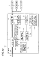
- Patent Literature 2 As a method of identifying the used appliance of the fluid in the related art, a method described in Patent Literature 2 is known. The configuration will be described with reference to Fig. 10 .
- a calculation unit 108 calculates the differentials of the gas flow rate measured by flow rate measurement unit 104 at regular intervals, and a differential conversion unit 112 classifies the differentials at regular time intervals into predetermined classifications using a flow rate classification table 110a stored in flow rate classification table holding unit 110, and converts the differentials to predetermined codes representing the classifications.
- An appliance identification unit 116 compares a code sequence generated by code sequence generation unit 114 using the codes converted by the differential conversion unit 112 with appliance-specific characteristic code sequences specific to the appliances stored in an appliance-specific code sequence information holding unit 118, and identifies the appliances.
- the flow rate changes in various ways depending on the state of usage, such as set temperature, the amount of hot water, or water temperature. For this reason, in the flow rate differential or the code sequence, erroneous determination may be made at the time of comparison with data registered in advance.
- the invention solves the problems of the related art, and an object of the invention is to simplify calculation, to reduce the amount of memory necessary for calculation, to absorb variations in the flow rate which changes in various ways depending on the state of usage, and to improve identification precision of a specific kind of appliance with a configuration which extracts characteristics of appliances.
- a flow rate measurement device includes: a flow rate measurement unit that is configured to measure a flow rate of a fluid flowing in a flow channel at a regular time interval; a calculation unit that is configured to calculate a plurality of differentials at regular time intervals in the flow rates measured by the flow rate measurement unit; a flow rate classification table in which a plurality of differential classifications classified according to the magnitude of the differentials are associated with codes representing the respective classifications; a differential conversion unit that is configured to convert the differentials calculated by the calculation unit to the codes on the basis of the flow rate classification table; an appliance characteristic extraction unit that is configured to generate a plurality of appliance-specific code sequences representing characteristics of appliances from a plurality of codes obtained at regular time intervals by the differential conversion unit or extract a plurality of appliance characteristic flow rates representing characteristics of appliances from the flow rates measured by the flow rate measurement unit; and an appliance identification unit that is configured to compare at least either the appliance characteristic code sequences extracted by the appliance characteristic extraction unit with appliance
- the flow rate measurement device of the aspect of the invention it becomes possible to simplify calculation, to reduce the amount of memory necessary for calculation, to absorb variations in the flow rate which changes in various ways depending on the state of usage, and to improve identification precision of a water heater with a configuration which extracts characteristics of appliances.
- a first aspect of the invention is configured to include: a flow rate measurement unit that is configured to measure a flow rate of a fluid flowing in a flow channel at a regular time interval; a calculation unit that is configured to calculate a plurality of differentials at regular time intervals in the flow rates measured by the flow rate measurement unit; a flow rate classification table in which a plurality of differential classifications classified according to the magnitude of the differentials are associated with codes representing the respective classifications; a differential conversion unit that is configured to convert the differentials calculated by the calculation unit to the codes on the basis of the flow rate classification table; an appliance characteristic extraction unit that is configured to generate a plurality of appliance-specific code sequences representing characteristics of appliances from a plurality of codes obtained at regular time intervals by the differential conversion unit or extract a plurality of appliance characteristic flow rates representing characteristics of appliances from the flow rates measured by the flow rate measurement unit; and an appliance identification unit that is configured to compare at least either the appliance characteristic code sequences extracted by the appliance characteristic extraction unit with appliance-specific characteristic code sequences specific to the appliances held in appliance-
- a second aspect of the invention is configured in the first aspect of the invention so that when the appliance identification unit has determined that the used appliance is the specific kind of appliance, and compares the used appliance in characteristics with a specific kind of appliance held in the appliance-specific characteristic information holding unit, and if an average flow rate of the current flow rate and the last flow rate extracted by the appliance characteristic extraction unit when a ratio of the last flow rate and the current flow rate is within a predetermined range is different from an average flow rate held in the appliance-specific characteristic information holding unit, the appliance identification unit determines that the used appliance is another specific kind of appliance.
- a third aspect of the invention is a program which causes a computer to function as a whole or a part of the flow rate measurement device as set forth in the first or second aspect of the invention.
- this program at least a portion of the program of the invention can be easily realized using a general-use computer or a server.
- the program may be recorded on a recording medium or may be distributed using a communication line, thereby simplifying program distribution or installation.
- Fig. 1 is a block diagram of a flow rate measurement device in Embodiment 1 of the invention.
- a gas meter 100 includes a flow channel 102, a flow rate measurement unit 104, a measured flow rate information storage unit 106, a calculation unit 108, a flow rate classification table holding unit 110, a differential conversion unit 112, an appliance characteristic extraction unit 214, an appliance identification unit 116, and an appliance-specific characteristic information holding unit 218.
- the gas meter 100 is disposed in the flow channel 102, and includes a shutoff unit 122 which shuts off gas in emergency or the like.
- An ultrasonic flowmeter serving as the flow rate measurement unit 104 emits ultrasonic waves with respect to gas as a fluid flowing in the flow channel 102 at regular time intervals and measures the gas flow rate, and a general ultrasonic flowmeter may be used.
- the measured flow rate information storage unit 106 stores target data in which a measured flow rate measured by the flow rate measurement unit 104 is described in association with the measurement time at which the measured flow rate is measured.
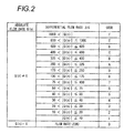
- the flow rate classification table holding unit 110 holds a flow rate classification table 110a shown in Fig. 2 in which a plurality of differential classifications classified according to the magnitude of the differentials are associated with codes representing the respective classifications.
- the flow rate classification table 110a serves as a conversion table which classifies the absolute values of the measured differentials into predetermined classifications and converts the differentials to predetermined codes representing the classifications.
- the number of classifications of the flow rate classification table 110a is not particularly limited, and in Fig. 2 , for example, the differentials are classified into 16 codes. Although a region where it is determined that the flow rate is zero is described, there are few cases where the flow rate measured in the actual device is completely zero because of a few variations. Accordingly, the condition that the flow rate is zero includes when the flow rate is approximately zero, substantially zero.
- the ranges of the classifications are fragmented with different flow rate intervals.
- the ranges of the classifications are fragmented with an increasing differential in the flow rate such that the codes 1 to 5 are 10 L/h, the codes 6 to B are 25 L/h, the codes C to D are 50 L/h, and the code E is 100 L/h.
- the interval decreases, thereby increasing identification precision.
- the codes A to F express 10 to 15 in hexadecimal, and magnitude comparison can be performed with the codes as numerical values.
- the differential conversion unit 112 converts the differentials calculated by the calculation unit 108 to the codes representing the respective classifications, into which the differentials at regular time interval (of ultrasonic wave emission) are classified, on the basis of the flow rate classification table 110a.
- the appliance characteristic extraction unit 214 generates an extracted code sequence representing the characteristics of the appliances from a measured code sequence obtained by actual measurement on the basis of a set of codes at regular time intervals obtained by the differential conversion unit 112.
- the measured code sequence expresses the change in the flow rate of the fluid in a pseudo manner.
- the appliance characteristic extraction unit 214 records the extracted code sequence representing the characteristics of the appliances in a memory (not shown) as necessary.
- the appliance characteristic extraction unit 214 monitors the gas flow rate measured by the flow rate measurement unit 104, extracts a plurality of appliance characteristic flow rates including, for example, the gentle ignition flow rate of the fan heater representing the characteristics of the appliances from the change in the flow rate, and stores the plurality of appliance characteristic flow rates in the memory (not shown) as necessary.
- the appliance identification unit 116 identifies a gas appliance using gas as a fluid on the basis of the extracted code sequence extracted by the appliance characteristic extraction unit 214 and the appliance characteristic flow rate.
- the appliance identification unit 116 compares the extracted code sequence with appliance-specific characteristic code sequences representing characteristic code sequences specific to the appliances stored in the appliance-specific characteristic information holding unit 218 in advance for the gas appliances or a plurality of appliance characteristic flow rates, and identifies a gas appliance using gas from a similarity relation or the like.
- the gas meter 100 is connected to a gas duct 19 on the upstream side, and is also connected to various gas appliances 13, 14, and 15, such as a hot plate, a fan heater, and floor heating, on the downstream side.
- the regular time interval may be 1 second or 2 seconds.
- the differential conversion unit 112 converts the absolute value of the differential ⁇ Q(n) calculated by the calculation unit 108 to a classification code, which is a code representing each of the classifications for classifying the differentials at regular time intervals, with reference to the flow rate classification table 110a of Fig. 2 .
- Figs. 3(a) to 3(d) show an example of conversion using the flow rate classification table. If a gas appliance A (for example, a fan heater) corresponding to one of the gas appliances 13, 14, and 15 of Fig. 1 starts to be activated and a gas flow rate is generated, as shown in "FLOW RATE" of Fig. 3(a) and a graph of Fig.
- the calculation unit 108 calculates a differential, and the differential conversion unit 112 converts the differential to a classification code (shown in a "CODE" sequence of Fig. 3(a) ).
- the appliance characteristic extraction unit 214 calculates the average value of the flow rates at that time and stores the average value as an intermediate stable flow rate which is one of the appliance characteristic flow rates. As shown in Fig. 3(a) , at the time 4 and the time 5, codes equal to or smaller than 2 appear continuously two times. In this case, the average value 154 L/h of the flow rate 150 L/h of the time 4 and the flow rate 158 L/h of the time 5 is stored as the intermediate stable flow rate.
- the appliance characteristic extraction unit 214 calculates the average value of the flow rates at that time, and stores the average value as a stable flow rate which is one of the appliance characteristic flow rates.
- codes are equal to or smaller than 2 appear continuously four times.
- the average value 203.75 L/h of the flow rate 203 L/h of the time 7, the flow rate 204 L/h of the time 8, the flow rate 204 L/h of the time 9, and the flow rate 204 L/h of the time 10 is stored as the stable flow rate.
- the stored intermediate stable flow rate corresponds to a gentle ignition flow rate (from a change point I to a change point II in the graph), the stable flow rate corresponds to a stable flow rate (after a change point III in the graph) immediately after ignition. It is thus understood that the appliance characteristic flow rates are sufficiently extracted.
- the appliance characteristic extraction unit 214 calculates the ratio of the previous flow rate and the current flow rate.
- the first predetermined flow rate and the second predetermined flow rate are provided to prevent erroneous detection at the time of the start of rise in the flow rate resulting from the measurement timing or erroneous detection at the time of the change in the flow rate under control after a steep rise in a water heater.
- ratio (1-current flow rate/last flow rate) ⁇ 100
- the ratio is zero when the current flow rate and the previous flow rate are the same, and is expressed in percentage.
- the average flow rate of the current flow rate at that time and the last flow rate is stored as an intermediate flow rate which is one of the appliance characteristic flow rates.
- the average value 147.5 L/h of the flow rate 145 L/h of the time 3 and the flow rate 150 L/h of the time 4 is stored as an intermediate flow rate. It is understood that, with this intermediate flow rate, even when the intermediate stable flow rate may not be detected, the appliance characteristics can be extracted, the appliance characteristic flow rates are extracted sufficiently compared to the intermediate stable flow rate 154 L/h.
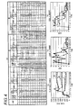
- Figs. 4(a) to 4(d) are diagrams showing a concept of characteristic extraction when using a water heater B. It is assumed that I, II, and III shown in Fig. 4(a) are due to differences in hot water supply temperature setting and measured using the same water heater B. Incidentally, I is set at 32°C, II is set at 60°C, and III is set at 43°C.
- Fig. 4(b) shows the change in the flow rate.
- flow rate control is activated based on the set temperature.
- various flow rates at different set temperatures are extracted. It is understood that, as shown in Fig. 4(c) , the change in a code (a code a of Fig. 4(a) ) converted by the differential conversion unit 112 on the basis of the differential (the differential ⁇ Qa of Fig. 4(a) ) between the current flow rate and the last flow rate calculated by the calculation unit 108 varies among I, II, and III.
- an appliance characteristic code sequence a of Fig. 5(a) an appliance characteristic code sequence extracted by the appliance characteristic extraction unit 214 shows different changes ( Fig. 5(b) ) among I, II, and III, and it becomes very difficult to determine to be the same appliance.
- the differential a differential ⁇ Qa of Fig. 4(a)
- the differential a differential ⁇ Qa of Fig. 4(a)
- any code of the first peak or the second peak data No. 2 or data No. 4 of a graph of Fig.
- 5(b) is equal to or greater than a first predetermined value, for example, equal to or greater than 11, when the first peak value or the second peak value of an appliance characteristic code sequence b extracted by the appliance characteristic extraction unit 214 from a code b converted by the differential conversion unit 112 on the basis of second differentials calculated by the calculation unit 108, for example, the differential (a differential ⁇ Qb of Fig. 4(a) ) between the current flow rate and the second last flow rate, for example, any code of the first peak or the second peak (data No. 2 or data No. 4) of a graph of Fig.
- 5(c) is equal to or greater than a first predetermined value, for example, equal to or greater than 12, and when the flow rate is equal to or higher than a predetermined flow rate, for example, 300 L/h no later than a predetermined number of times, for example, three times from a rise in the flow rate, the appliance identification unit 116 determines that a used appliance is a water heater. Therefore, it becomes possible to determine that the used appliance is a water heater even when the set temperature of the water heater differs, flow rate control is activated immediately after the rise in the flow rate, and the flow rate varies.
- a predetermined flow rate for example, 300 L/h no later than a predetermined number of times, for example, three times from a rise in the flow rate
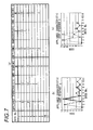
- Figs. 6(a) to 6(d) are diagrams showing a concept of characteristic extraction when using a water heater C. It is assumed that IV, V, and VI shown in Fig. 6(a) are due to a difference in water supply temperature setting and measured using the same water heater C. Incidentally, IV is set at 37°C, V is set at 60°C, and VI is set at 43°C.
- a first predetermined value for example, equal to or greater than 12
- a predetermined flow rate for example, 300 L/h no later than a predetermined number of times from the rise in the flow rate
- the appliance-specific characteristic information holding unit 218 When the characteristics of the water heater B described in Embodiment 1 are held in the appliance-specific characteristic information holding unit 218, the water heater C is used, and the appliance identification unit 116 identifies a water heater. Meanwhile, it is difficult to identify the water heater C and the water heater B held in the appliance-specific characteristic information holding unit 218.
- comparison is performed using the intermediate flow rate which is the average flow rate of the current flow rate and the last flow rate extracted by the appliance characteristic extraction unit 214 when the ratio of the last flow rate and the current flow rate.
- the average value 709.5 L/h of the flow rate 721 L/h of the time 3 and the flow rate 698 L/h of the time 4 becomes an intermediate flow rate.
- the average value 686.5 L/h of the flow rate 673 L/h of the time 3 and the flow rate 700 L/h of the time 4 becomes an intermediate flow rate.
- the average value 703 L/h of the flow rate 718 L/h of the time 3 and the flow rate 688 L/h of the time 4 becomes an intermediate flow rate.
- the intermediate flow rate is stored. This is the same as a case where, when the ratio (current flow rate/previous flow rate) of the current flow rate and the previous flow rate is close to 1, the intermediate flow rate is stored.
- Fig. 8(a) shows a list of determination contents of a used water heater when any of I, II, and III of the water heater B is held in the appliance-specific characteristic information holding unit 218.
- Fig. 8(b) shows a list of determination contents of a used water heater when any of IV, V, and VI of the water heater C is held in the appliance-specific characteristic information holding unit 218.
- "o" represents the determination to be the same appliance
- " ⁇ " represents the determination to be different appliances.
- the intermediate flow rate is 709.5 L/h. If the flow rate is within +10% of the intermediate flow rate, it is determined to be the same appliance. In this case, the determination range is from 638.55 L/h to 780.45 L/h.
- the used appliances are I, II, and III, all are determined to be the same appliance.
- the appliance being held is II or III, and when the used appliances are I, II, and III, all are determined to be the same appliance.
- the used appliances are IV, V, and VI of the water heater C, all are determined to be different appliances, and the water heater B and the water heater C can be determined to be different appliances.
- appliance characteristic extraction using codes converted from flow rate differentials at regular time intervals has been described, more accurate characteristic extraction may be performed using the flow rate differentials.
- an appliance registration mode may be provided, an appliance may be repeatedly operated on site, the appliance characteristic may be extracted and averaged, and the characteristic may be registered as an appliance-specific characteristic code sequence or an appliance-specific characteristic flow rate.
- An appliance-specific characteristic code sequence or an appliance-specific characteristic flow rate may be registered automatically by learning without setting an appliance-specific characteristic code sequence or an appliance-specific characteristic flow rate in advance.
- the flow rate measurement device can extract characteristics of appliances, and can be thus applied for specifying a used appliance connected to the downstream side of the flow rate measurement device or grouping even in an industrial flowmeter or a water meter.
Landscapes
- Physics & Mathematics (AREA)
- Fluid Mechanics (AREA)
- General Physics & Mathematics (AREA)
- Measuring Volume Flow (AREA)
Applications Claiming Priority (2)
| Application Number | Priority Date | Filing Date | Title |
|---|---|---|---|
| JP2009251700A JP5589351B2 (ja) | 2009-11-02 | 2009-11-02 | 流量計測装置 |
| PCT/JP2010/006463 WO2011052241A1 (ja) | 2009-11-02 | 2010-11-02 | 流量計測装置 |
Publications (3)
| Publication Number | Publication Date |
|---|---|
| EP2498071A1 true EP2498071A1 (de) | 2012-09-12 |
| EP2498071A4 EP2498071A4 (de) | 2015-01-28 |
| EP2498071B1 EP2498071B1 (de) | 2021-05-19 |
Family
ID=43921673
Family Applications (1)
| Application Number | Title | Priority Date | Filing Date |
|---|---|---|---|
| EP10826376.5A Active EP2498071B1 (de) | 2009-11-02 | 2010-11-02 | Durchsatzmessvorrichtung |
Country Status (5)
| Country | Link |
|---|---|
| US (1) | US9026381B2 (de) |
| EP (1) | EP2498071B1 (de) |
| JP (1) | JP5589351B2 (de) |
| CN (1) | CN102597717B (de) |
| WO (1) | WO2011052241A1 (de) |
Cited By (1)
| Publication number | Priority date | Publication date | Assignee | Title |
|---|---|---|---|---|
| EP3410077A4 (de) * | 2016-01-29 | 2019-01-30 | Panasonic Intellectual Property Management Co., Ltd. | Flussmessvorrichtung |
Families Citing this family (5)
| Publication number | Priority date | Publication date | Assignee | Title |
|---|---|---|---|---|
| US20110010110A1 (en) * | 2008-03-07 | 2011-01-13 | Panasonic Corporation | Gas meter and gas meter system |
| US20130110413A1 (en) * | 2011-10-27 | 2013-05-02 | Brian Michael Schork | Estimating gas usage in a gas burning device |
| JP2013221853A (ja) * | 2012-04-17 | 2013-10-28 | Panasonic Corp | 流量計測装置 |
| JP6361938B2 (ja) * | 2016-01-14 | 2018-07-25 | パナソニックIpマネジメント株式会社 | 流量計測装置 |
| CN115560816B (zh) * | 2022-03-18 | 2024-08-30 | 荣成市宇翔实业有限公司 | 燃气表控制方法 |
Family Cites Families (13)
| Publication number | Priority date | Publication date | Assignee | Title |
|---|---|---|---|---|
| DE4042557C2 (de) * | 1990-12-06 | 1996-11-28 | Lehmann Martin | Verfahren zur Analyse von Gasproben und Analyseanordnung |
| JP2000227348A (ja) * | 1999-02-05 | 2000-08-15 | Osaka Gas Co Ltd | ガス遮断情報生成装置 |
| CA2581107C (en) * | 2004-09-27 | 2013-01-08 | Micro Motion, Inc. | In-flow determination of left and right eigenvectors in a coriolis flowmeter |
| TWI386629B (zh) | 2005-05-09 | 2013-02-21 | 松下電器產業股份有限公司 | Flow measurement device |
| JP4729971B2 (ja) | 2005-05-09 | 2011-07-20 | パナソニック株式会社 | ガスメータ装置 |
| JP4804914B2 (ja) * | 2005-12-28 | 2011-11-02 | パナソニック株式会社 | ガスメータ |
| CN102116646B (zh) * | 2006-10-25 | 2012-12-05 | 松下电器产业株式会社 | 流量测量装置 |
| EP2098833B1 (de) * | 2006-12-28 | 2016-04-13 | Panasonic Corporation | Strömungsmesser und gasversorgungssystem |
| CN101765760B (zh) * | 2007-05-28 | 2011-11-02 | 松下电器产业株式会社 | 记录物理量变化历史的方法及其程序、流量测量装置以及流体供应系统 |
| CN101779105B (zh) | 2007-06-12 | 2012-03-21 | 松下电器产业株式会社 | 流量测量装置和流体供应系统 |
| JP4391550B2 (ja) | 2007-06-12 | 2009-12-24 | パナソニック株式会社 | 流量計測装置および流体供給システム |
| JP4976940B2 (ja) * | 2007-07-09 | 2012-07-18 | 東光東芝メーターシステムズ株式会社 | ガス器具判別装置 |
| JP4861943B2 (ja) * | 2007-09-21 | 2012-01-25 | パナソニック株式会社 | 流量計測装置 |
-
2009
- 2009-11-02 JP JP2009251700A patent/JP5589351B2/ja active Active
-
2010
- 2010-11-02 WO PCT/JP2010/006463 patent/WO2011052241A1/ja not_active Ceased
- 2010-11-02 CN CN2010800495771A patent/CN102597717B/zh active Active
- 2010-11-02 EP EP10826376.5A patent/EP2498071B1/de active Active
- 2010-11-02 US US13/505,554 patent/US9026381B2/en not_active Expired - Fee Related
Cited By (2)
| Publication number | Priority date | Publication date | Assignee | Title |
|---|---|---|---|---|
| EP3410077A4 (de) * | 2016-01-29 | 2019-01-30 | Panasonic Intellectual Property Management Co., Ltd. | Flussmessvorrichtung |
| US11397005B2 (en) | 2016-01-29 | 2022-07-26 | Panasonic Intellectual Property Management Co., Ltd. | Flow measurement device |
Also Published As
| Publication number | Publication date |
|---|---|
| JP5589351B2 (ja) | 2014-09-17 |
| JP2011095201A (ja) | 2011-05-12 |
| EP2498071B1 (de) | 2021-05-19 |
| CN102597717A (zh) | 2012-07-18 |
| CN102597717B (zh) | 2013-09-04 |
| WO2011052241A1 (ja) | 2011-05-05 |
| US20120221258A1 (en) | 2012-08-30 |
| US9026381B2 (en) | 2015-05-05 |
| EP2498071A4 (de) | 2015-01-28 |
Similar Documents
| Publication | Publication Date | Title |
|---|---|---|
| EP2498070B1 (de) | Durchsatzmessvorrichtung | |
| US9026381B2 (en) | Flow rate measurement device | |
| JP5793651B2 (ja) | 流量計測装置 | |
| CN102116646B (zh) | 流量测量装置 | |
| US9200939B2 (en) | Flow rate measurement apparatus and fluid supply system | |
| CN106841773B (zh) | 识别恶性负载的方法和系统 | |
| CN107209040B (zh) | 流量测量装置 | |
| EP2498072B1 (de) | Durchflussmessvorrichtung | |
| EP2405242B1 (de) | Durchsatzmessvorrichtung | |
| CN101535778A (zh) | 流量测量装置 | |
| EP3404374B1 (de) | Durchflussmessvorrichtung | |
| JP5304595B2 (ja) | 流量計測装置 | |
| JP2012242229A (ja) | 流量計測装置 | |
| US11215487B2 (en) | Flow rate measurement device | |
| CN113405620A (zh) | 基于零流量识别降低超声波表功耗及零流量校准的方法 | |
| US20190219420A1 (en) | Flow rate measuring device |
Legal Events
| Date | Code | Title | Description |
|---|---|---|---|
| PUAI | Public reference made under article 153(3) epc to a published international application that has entered the european phase |
Free format text: ORIGINAL CODE: 0009012 |
|
| 17P | Request for examination filed |
Effective date: 20120502 |
|
| AK | Designated contracting states |
Kind code of ref document: A1 Designated state(s): AL AT BE BG CH CY CZ DE DK EE ES FI FR GB GR HR HU IE IS IT LI LT LU LV MC MK MT NL NO PL PT RO RS SE SI SK SM TR |
|
| DAX | Request for extension of the european patent (deleted) | ||
| A4 | Supplementary search report drawn up and despatched |
Effective date: 20150107 |
|
| RIC1 | Information provided on ipc code assigned before grant |
Ipc: G01F 3/22 20060101AFI20141219BHEP Ipc: G01F 15/04 20060101ALN20141219BHEP Ipc: G01F 15/00 20060101ALI20141219BHEP Ipc: G01F 15/075 20060101ALN20141219BHEP |
|
| GRAP | Despatch of communication of intention to grant a patent |
Free format text: ORIGINAL CODE: EPIDOSNIGR1 |
|
| STAA | Information on the status of an ep patent application or granted ep patent |
Free format text: STATUS: GRANT OF PATENT IS INTENDED |
|
| INTG | Intention to grant announced |
Effective date: 20201218 |
|
| GRAS | Grant fee paid |
Free format text: ORIGINAL CODE: EPIDOSNIGR3 |
|
| GRAA | (expected) grant |
Free format text: ORIGINAL CODE: 0009210 |
|
| STAA | Information on the status of an ep patent application or granted ep patent |
Free format text: STATUS: THE PATENT HAS BEEN GRANTED |
|
| AK | Designated contracting states |
Kind code of ref document: B1 Designated state(s): AL AT BE BG CH CY CZ DE DK EE ES FI FR GB GR HR HU IE IS IT LI LT LU LV MC MK MT NL NO PL PT RO RS SE SI SK SM TR |
|
| REG | Reference to a national code |
Ref country code: GB Ref legal event code: FG4D |
|
| REG | Reference to a national code |
Ref country code: CH Ref legal event code: EP |
|
| REG | Reference to a national code |
Ref country code: DE Ref legal event code: R096 Ref document number: 602010067015 Country of ref document: DE |
|
| REG | Reference to a national code |
Ref country code: AT Ref legal event code: REF Ref document number: 1394432 Country of ref document: AT Kind code of ref document: T Effective date: 20210615 |
|
| REG | Reference to a national code |
Ref country code: IE Ref legal event code: FG4D |
|
| REG | Reference to a national code |
Ref country code: LT Ref legal event code: MG9D |
|
| REG | Reference to a national code |
Ref country code: AT Ref legal event code: MK05 Ref document number: 1394432 Country of ref document: AT Kind code of ref document: T Effective date: 20210519 |
|
| REG | Reference to a national code |
Ref country code: NL Ref legal event code: MP Effective date: 20210519 |
|
| PG25 | Lapsed in a contracting state [announced via postgrant information from national office to epo] |
Ref country code: FI Free format text: LAPSE BECAUSE OF FAILURE TO SUBMIT A TRANSLATION OF THE DESCRIPTION OR TO PAY THE FEE WITHIN THE PRESCRIBED TIME-LIMIT Effective date: 20210519 Ref country code: LT Free format text: LAPSE BECAUSE OF FAILURE TO SUBMIT A TRANSLATION OF THE DESCRIPTION OR TO PAY THE FEE WITHIN THE PRESCRIBED TIME-LIMIT Effective date: 20210519 Ref country code: BG Free format text: LAPSE BECAUSE OF FAILURE TO SUBMIT A TRANSLATION OF THE DESCRIPTION OR TO PAY THE FEE WITHIN THE PRESCRIBED TIME-LIMIT Effective date: 20210819 Ref country code: AT Free format text: LAPSE BECAUSE OF FAILURE TO SUBMIT A TRANSLATION OF THE DESCRIPTION OR TO PAY THE FEE WITHIN THE PRESCRIBED TIME-LIMIT Effective date: 20210519 Ref country code: HR Free format text: LAPSE BECAUSE OF FAILURE TO SUBMIT A TRANSLATION OF THE DESCRIPTION OR TO PAY THE FEE WITHIN THE PRESCRIBED TIME-LIMIT Effective date: 20210519 |
|
| PG25 | Lapsed in a contracting state [announced via postgrant information from national office to epo] |
Ref country code: ES Free format text: LAPSE BECAUSE OF FAILURE TO SUBMIT A TRANSLATION OF THE DESCRIPTION OR TO PAY THE FEE WITHIN THE PRESCRIBED TIME-LIMIT Effective date: 20210519 Ref country code: PT Free format text: LAPSE BECAUSE OF FAILURE TO SUBMIT A TRANSLATION OF THE DESCRIPTION OR TO PAY THE FEE WITHIN THE PRESCRIBED TIME-LIMIT Effective date: 20210920 Ref country code: PL Free format text: LAPSE BECAUSE OF FAILURE TO SUBMIT A TRANSLATION OF THE DESCRIPTION OR TO PAY THE FEE WITHIN THE PRESCRIBED TIME-LIMIT Effective date: 20210519 Ref country code: NO Free format text: LAPSE BECAUSE OF FAILURE TO SUBMIT A TRANSLATION OF THE DESCRIPTION OR TO PAY THE FEE WITHIN THE PRESCRIBED TIME-LIMIT Effective date: 20210819 Ref country code: IS Free format text: LAPSE BECAUSE OF FAILURE TO SUBMIT A TRANSLATION OF THE DESCRIPTION OR TO PAY THE FEE WITHIN THE PRESCRIBED TIME-LIMIT Effective date: 20210919 Ref country code: GR Free format text: LAPSE BECAUSE OF FAILURE TO SUBMIT A TRANSLATION OF THE DESCRIPTION OR TO PAY THE FEE WITHIN THE PRESCRIBED TIME-LIMIT Effective date: 20210820 Ref country code: LV Free format text: LAPSE BECAUSE OF FAILURE TO SUBMIT A TRANSLATION OF THE DESCRIPTION OR TO PAY THE FEE WITHIN THE PRESCRIBED TIME-LIMIT Effective date: 20210519 Ref country code: SE Free format text: LAPSE BECAUSE OF FAILURE TO SUBMIT A TRANSLATION OF THE DESCRIPTION OR TO PAY THE FEE WITHIN THE PRESCRIBED TIME-LIMIT Effective date: 20210519 Ref country code: RS Free format text: LAPSE BECAUSE OF FAILURE TO SUBMIT A TRANSLATION OF THE DESCRIPTION OR TO PAY THE FEE WITHIN THE PRESCRIBED TIME-LIMIT Effective date: 20210519 |
|
| PG25 | Lapsed in a contracting state [announced via postgrant information from national office to epo] |
Ref country code: NL Free format text: LAPSE BECAUSE OF FAILURE TO SUBMIT A TRANSLATION OF THE DESCRIPTION OR TO PAY THE FEE WITHIN THE PRESCRIBED TIME-LIMIT Effective date: 20210519 |
|
| PG25 | Lapsed in a contracting state [announced via postgrant information from national office to epo] |
Ref country code: RO Free format text: LAPSE BECAUSE OF FAILURE TO SUBMIT A TRANSLATION OF THE DESCRIPTION OR TO PAY THE FEE WITHIN THE PRESCRIBED TIME-LIMIT Effective date: 20210519 Ref country code: EE Free format text: LAPSE BECAUSE OF FAILURE TO SUBMIT A TRANSLATION OF THE DESCRIPTION OR TO PAY THE FEE WITHIN THE PRESCRIBED TIME-LIMIT Effective date: 20210519 Ref country code: CZ Free format text: LAPSE BECAUSE OF FAILURE TO SUBMIT A TRANSLATION OF THE DESCRIPTION OR TO PAY THE FEE WITHIN THE PRESCRIBED TIME-LIMIT Effective date: 20210519 Ref country code: DK Free format text: LAPSE BECAUSE OF FAILURE TO SUBMIT A TRANSLATION OF THE DESCRIPTION OR TO PAY THE FEE WITHIN THE PRESCRIBED TIME-LIMIT Effective date: 20210519 Ref country code: SM Free format text: LAPSE BECAUSE OF FAILURE TO SUBMIT A TRANSLATION OF THE DESCRIPTION OR TO PAY THE FEE WITHIN THE PRESCRIBED TIME-LIMIT Effective date: 20210519 Ref country code: SK Free format text: LAPSE BECAUSE OF FAILURE TO SUBMIT A TRANSLATION OF THE DESCRIPTION OR TO PAY THE FEE WITHIN THE PRESCRIBED TIME-LIMIT Effective date: 20210519 |
|
| REG | Reference to a national code |
Ref country code: DE Ref legal event code: R097 Ref document number: 602010067015 Country of ref document: DE |
|
| PLBE | No opposition filed within time limit |
Free format text: ORIGINAL CODE: 0009261 |
|
| STAA | Information on the status of an ep patent application or granted ep patent |
Free format text: STATUS: NO OPPOSITION FILED WITHIN TIME LIMIT |
|
| 26N | No opposition filed |
Effective date: 20220222 |
|
| PG25 | Lapsed in a contracting state [announced via postgrant information from national office to epo] |
Ref country code: IS Free format text: LAPSE BECAUSE OF FAILURE TO SUBMIT A TRANSLATION OF THE DESCRIPTION OR TO PAY THE FEE WITHIN THE PRESCRIBED TIME-LIMIT Effective date: 20210919 Ref country code: AL Free format text: LAPSE BECAUSE OF FAILURE TO SUBMIT A TRANSLATION OF THE DESCRIPTION OR TO PAY THE FEE WITHIN THE PRESCRIBED TIME-LIMIT Effective date: 20210519 |
|
| PG25 | Lapsed in a contracting state [announced via postgrant information from national office to epo] |
Ref country code: MC Free format text: LAPSE BECAUSE OF FAILURE TO SUBMIT A TRANSLATION OF THE DESCRIPTION OR TO PAY THE FEE WITHIN THE PRESCRIBED TIME-LIMIT Effective date: 20210519 |
|
| REG | Reference to a national code |
Ref country code: CH Ref legal event code: PL |
|
| PG25 | Lapsed in a contracting state [announced via postgrant information from national office to epo] |
Ref country code: LU Free format text: LAPSE BECAUSE OF NON-PAYMENT OF DUE FEES Effective date: 20211102 Ref country code: IT Free format text: LAPSE BECAUSE OF FAILURE TO SUBMIT A TRANSLATION OF THE DESCRIPTION OR TO PAY THE FEE WITHIN THE PRESCRIBED TIME-LIMIT Effective date: 20210519 Ref country code: BE Free format text: LAPSE BECAUSE OF NON-PAYMENT OF DUE FEES Effective date: 20211130 |
|
| REG | Reference to a national code |
Ref country code: BE Ref legal event code: MM Effective date: 20211130 |
|
| PG25 | Lapsed in a contracting state [announced via postgrant information from national office to epo] |
Ref country code: IE Free format text: LAPSE BECAUSE OF NON-PAYMENT OF DUE FEES Effective date: 20211102 |
|
| PG25 | Lapsed in a contracting state [announced via postgrant information from national office to epo] |
Ref country code: HU Free format text: LAPSE BECAUSE OF FAILURE TO SUBMIT A TRANSLATION OF THE DESCRIPTION OR TO PAY THE FEE WITHIN THE PRESCRIBED TIME-LIMIT; INVALID AB INITIO Effective date: 20101102 Ref country code: CY Free format text: LAPSE BECAUSE OF FAILURE TO SUBMIT A TRANSLATION OF THE DESCRIPTION OR TO PAY THE FEE WITHIN THE PRESCRIBED TIME-LIMIT Effective date: 20210519 |
|
| PG25 | Lapsed in a contracting state [announced via postgrant information from national office to epo] |
Ref country code: LI Free format text: LAPSE BECAUSE OF NON-PAYMENT OF DUE FEES Effective date: 20220630 Ref country code: CH Free format text: LAPSE BECAUSE OF NON-PAYMENT OF DUE FEES Effective date: 20220630 |
|
| PG25 | Lapsed in a contracting state [announced via postgrant information from national office to epo] |
Ref country code: MK Free format text: LAPSE BECAUSE OF FAILURE TO SUBMIT A TRANSLATION OF THE DESCRIPTION OR TO PAY THE FEE WITHIN THE PRESCRIBED TIME-LIMIT Effective date: 20210519 |
|
| PG25 | Lapsed in a contracting state [announced via postgrant information from national office to epo] |
Ref country code: TR Free format text: LAPSE BECAUSE OF FAILURE TO SUBMIT A TRANSLATION OF THE DESCRIPTION OR TO PAY THE FEE WITHIN THE PRESCRIBED TIME-LIMIT Effective date: 20210519 |
|
| PG25 | Lapsed in a contracting state [announced via postgrant information from national office to epo] |
Ref country code: MT Free format text: LAPSE BECAUSE OF FAILURE TO SUBMIT A TRANSLATION OF THE DESCRIPTION OR TO PAY THE FEE WITHIN THE PRESCRIBED TIME-LIMIT Effective date: 20210519 |
|
| PGFP | Annual fee paid to national office [announced via postgrant information from national office to epo] |
Ref country code: DE Payment date: 20251119 Year of fee payment: 16 |
|
| PGFP | Annual fee paid to national office [announced via postgrant information from national office to epo] |
Ref country code: GB Payment date: 20251121 Year of fee payment: 16 |
|
| PGFP | Annual fee paid to national office [announced via postgrant information from national office to epo] |
Ref country code: FR Payment date: 20251125 Year of fee payment: 16 |
|
| REG | Reference to a national code |
Ref country code: DE Ref legal event code: R084 Ref document number: 602010067015 Country of ref document: DE |
|
| REG | Reference to a national code |
Ref country code: GB Ref legal event code: 746 Effective date: 20260323 |