EP2498088B1 - Bestimmung eines elektrischen Merkmals von flüssigkeitshaltigen Partikeln - Google Patents
Bestimmung eines elektrischen Merkmals von flüssigkeitshaltigen Partikeln Download PDFInfo
- Publication number
- EP2498088B1 EP2498088B1 EP20120157958 EP12157958A EP2498088B1 EP 2498088 B1 EP2498088 B1 EP 2498088B1 EP 20120157958 EP20120157958 EP 20120157958 EP 12157958 A EP12157958 A EP 12157958A EP 2498088 B1 EP2498088 B1 EP 2498088B1
- Authority
- EP
- European Patent Office
- Prior art keywords
- web
- filtering web
- liquid
- measuring conduit
- filtering
- Prior art date
- Legal status (The legal status is an assumption and is not a legal conclusion. Google has not performed a legal analysis and makes no representation as to the accuracy of the status listed.)
- Not-in-force
Links
- 239000007788 liquid Substances 0.000 title claims description 54
- 239000002245 particle Substances 0.000 title claims description 38
- 238000001914 filtration Methods 0.000 claims description 76
- 238000005259 measurement Methods 0.000 claims description 50
- 238000004891 communication Methods 0.000 claims description 10
- 239000012530 fluid Substances 0.000 claims description 9
- 238000012545 processing Methods 0.000 claims description 9
- 238000000034 method Methods 0.000 claims description 5
- 230000000737 periodic effect Effects 0.000 claims description 4
- 230000000717 retained effect Effects 0.000 claims description 3
- 238000006073 displacement reaction Methods 0.000 claims description 2
- 238000007493 shaping process Methods 0.000 claims description 2
- 230000014759 maintenance of location Effects 0.000 claims 1
- 238000004140 cleaning Methods 0.000 description 6
- 230000000694 effects Effects 0.000 description 3
- 239000002699 waste material Substances 0.000 description 3
- 239000000463 material Substances 0.000 description 2
- 230000004888 barrier function Effects 0.000 description 1
- 239000008280 blood Substances 0.000 description 1
- 210000004369 blood Anatomy 0.000 description 1
- 239000000084 colloidal system Substances 0.000 description 1
- 230000000052 comparative effect Effects 0.000 description 1
- 239000000835 fiber Substances 0.000 description 1
- 239000010865 sewage Substances 0.000 description 1
- 239000002689 soil Substances 0.000 description 1
- 239000000725 suspension Substances 0.000 description 1
- 238000012360 testing method Methods 0.000 description 1
- XLYOFNOQVPJJNP-UHFFFAOYSA-N water Substances O XLYOFNOQVPJJNP-UHFFFAOYSA-N 0.000 description 1
- 238000004804 winding Methods 0.000 description 1
Images

Classifications
-
- G—PHYSICS
- G01—MEASURING; TESTING
- G01N—INVESTIGATING OR ANALYSING MATERIALS BY DETERMINING THEIR CHEMICAL OR PHYSICAL PROPERTIES
- G01N27/00—Investigating or analysing materials by the use of electric, electrochemical, or magnetic means
- G01N27/60—Investigating or analysing materials by the use of electric, electrochemical, or magnetic means by investigating electrostatic variables, e.g. electrographic flaw testing
-
- G—PHYSICS
- G01—MEASURING; TESTING
- G01N—INVESTIGATING OR ANALYSING MATERIALS BY DETERMINING THEIR CHEMICAL OR PHYSICAL PROPERTIES
- G01N33/00—Investigating or analysing materials by specific methods not covered by groups G01N1/00 - G01N31/00
- G01N33/34—Paper
- G01N33/343—Paper pulp
Definitions
- the present invention relates to the determination of an electrical characteristic, in particular the streaming potential or zeta-potential, of a particles containing liquid.
- Determination of the zeta-potential is also known for suspensions, fibers containing liquids, colloids, (human) blood, etc.
- WO2007045481 discloses an example of a system for the determination of the zeta-potential.
- the invention provides a system according to the preamble of claim 1, which is characterized in that the system further comprises:
- the system according to the present invention can be used for liquids having a very low particles content and/or with very small particles, as the plug is established using the filtering web.
- the web is appropriately chosen for the liquid to be handled.
- An advantage of the system according to the invention is that the plug is established on the filtering web, and discarded along with the filtering web. This avoids a problem of known systems with a sieve type electrode to establish the plug, wherein said sieve type electrode is soiled by the material forming the plug and in practice requires extensive cleaning before it is suitable for a further measurement cycle.
- the system according to the present invention is primarily envisaged as a batch system, wherein a batch of liquid to be examined is introduced into the measurement apparatus.
- the system can be used as an "in-line determination system", wherein a (sample) flow of liquid is fed to the measurement apparatus, e.g. periodically.
- one of the electrodes comprises one or more members extending across the measuring conduit, e.g. the electrode being embodied as a metallic sieve, and the path for the filtering web extends along said electrode such that in use the filtering web is supported by the one or more members of said electrode.
- the one or more members of said filtering web supporting electrode support the filtering web at the side thereof opposite from the side where the plug of particles is established. Thereby the filtering web avoids soiling of said electrode.
- the other electrode can e.g. be embodied as an annular electrode having a central opening for the passage of particles containing liquid, e.g. received in the wall of the measurement conduit.
- the filtering web is a filtering paper web.
- the system includes a roll of disposable filtering web
- the web feed mechanism includes a source roller assembly adapted to unroll the roll of filtering web and a take-up roller assembly adapted to roll up the used filtering web.
- controllable variable liquid flow means comprise a vacuum device that is in fluid communication with the measuring conduit and is adapted to establish a pressure difference variation across the plug of articles during the measurement cycle.
- the vacuum device comprises a piston and cylinder device having a cylinder and a reciprocable piston therein delimiting a variable volume chamber in fluid communication with said measuring conduit with an associated drive motor for effecting a controlled displacement of said piston with respect to said cylinder.
- the vacuum device is adapted to cause a predetermined periodic variation of the pressure in said variable volume chamber.
- the measurement apparatus includes a liquid container, e.g. an open topped liquid container, which can contain a batch of liquid to be analyzed, said container being in fluid communication with said measurement conduit.
- the measurement conduit connects to the bottom of the container and extends downward, e.g. vertically, from said bottom.
- the measuring conduit is arranged in vertical orientation within a housing, said first and second electrode being arranged above one another.
- the system includes a pressure sensor that allows to measure the pressure in a variable volume chamber that is in communication with the measurement conduit, and a control means associated with the drive motor that effects variation of the volume of the variable volume chamber, said control means being adapted to establish a predetermined pattern of variation of the pressure in said variable volume chamber.
- the drive motor is a linear actuator, e.g. a linear motor or a pneumatic or hydraulic cylinder, preferably including a position sensor to detect a piston position and/or speed, e.g. with a servo control loop, e.g. a linear motor or a pneumatic or hydraulic cylinder.
- the drive motor has a rotary output shaft, connected to the piston via a crankshaft - connecting rod mechanism.
- system further comprises a pressure sensor adapted to measure the pressure difference across the plug of particles, said pressure sensor assembly being interconnected to said signal processing means.
- the system comprises a conductivity sensor adapted to measure the conductivity of the liquid, e.g. whilst in said measurement conduit, e.g. the first and second electrodes being part of the conductivity sensor, said conductivity sensor being interconnected to said signal processing means.
- the invention also relates to a method for the determination of an electrical characteristic, in particular the streaming potential or zeta-potential, of a particles containing liquid, said method including the use of a system according to the invention.
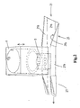
- the system shown here is designed for measurements to be performed on batches of particles containing liquid, e.g. for use in a laboratory.
- the system includes a measurement apparatus having a liquid container 1, here, is preferred, an open topped liquid container 1, which can contain a batch of liquid to be analyzed.
- the container 1 is in fluid communication with a measurement conduit 2.
- the container 1 is integral with a liftable measuring conduit member 3, that forms a portion, here an upper part 2a, of the measuring conduit.
- the member 3, in this example along with the container 1, is movable between an operative and a retracted position, here a lowered and a raised position. The operation will be explained in more detail below.
- the conduit member 3 includes a first electrode 4 which contacts the liquid in the measuring conduit during the measurement cycle, as is preferred the electrode 4 is a ring electrode, e.g. having an inner diameter the same as the diameter of the conduit 2.
- the apparatus here further comprises a housing 5 in which a further, here lower, part 2b of the measuring conduit 2 is present.
- the housing 5 supports a second electrode 6, spaced from the first electrode 4, here in vertical direction.
- the second electrode 6 comprises one or more members extending across the measuring conduit, here the electrode 6 is embodied as a sieve, e.g. a metallic sieve.
- a signal processing and control means 10 is connected to the first and second electrodes 4, 6 for the determination of the electrical characteristic of the liquid in a measurement cycle, such means 10 are known in the art.
- the measuring conduit 2 is arranged in vertical orientation, said first and second electrodes 4, 6 being arranged above one another.
- the system further includes an intermittent filtering web feed mechanism for feeding a filtering web 21 to the position across the measuring conduit 2.
- the filtering web here is provided in the form of a roll 20 of disposable filtering web 21, as is preferred.
- a zigzag folded continuous disposable filtering web is provided.
- the apparatus preferably comprises a source roller assembly (not shown here, e.g. a supporting spindle) adapted to unroll or allow for the unrolling of the roll 20 of filtering web 21.
- the web 21 is a paper filtering web. It is noted that filtering webs are commercially available with well defined filtering properties. A suitable web can be chosen in combination with the liquid to be examined, possibly some comparative tests can be done to select an optimal filtering web.
- the measurement apparatus has a path for the disposable filtering web that extends across the measuring conduit, so that a portion of the web 21 in said measuring conduit forms the particles retaining filter. As will be explained a plug of particles will form on said web during the measurement cycle.
- the mechanism includes a driven take-up roller 22, e.g. with an electric drive motor, that is operated such that the web is intermittently advanced from the supply roll 20 to the take-up roller 22.
- a driven take-up roller 22 e.g. with an electric drive motor
- said intermittent advancing can be realized with differently embodied motorized intermittent advancing means.
- the intermittent filtering web feed mechanism is adapted to advance the filtering web intermittently so that as to replace the portion of filtering web 21 used as particles retaining filter in a measurement cycle for a clean and non-used portion of the filtering web for the next measurement cycle.
- the path for the filtering web 21 extends along the second electrode 6, here - as is preferred - above the electrode, such that in use the filtering web 21 (and the plug formed thereon) is supported by the one or more members of said electrode 6.
- the members of the second electrode 6 support the filtering web 21 at the side thereof opposite from the side where the plug is established.
- the liftable measuring conduit member 3 sealingly engages on the filtering web 21 at the side where the plug of particles is formed during the measurement cycle.
- the filtering web 21 is then suitably clamped between said member 3 and the housing 5.
- the liftable measuring conduit member 3 In the retracted, here raised, position, the liftable measuring conduit member 3 is spaced from the filtering web 21 so as to allow for the used portion of the filtering web 21 with the plug of particles thereon to be advanced in a discharge direction.
- a lifting means 9 is associated with the liftable member 3, here also with the container 1, to perform the motion of the member 3 when desired.
- the lifting means 9 is linked to the control means 10, here via control line a, to obtain an automated operation of the system.
- the advancing means here take-up roller drive
- the means 10 here via control line b, to obtain an automated operation of the system.
- the system includes a waste container, e.g. a portable container 30, in which the liquid is received after performing a measurement cycle, here via discharge conduit 7 that is selectively connectable to lower conduit part 2b via the (electronic controlled) valve 8.
- a waste container e.g. a portable container 30, in which the liquid is received after performing a measurement cycle, here via discharge conduit 7 that is selectively connectable to lower conduit part 2b via the (electronic controlled) valve 8.
- the web feed mechanism is adapted to advance the web 21 with the plug thereon so that said plug falls into a waste collection container as well, preferably both the plug and the liquid being received in a common waste container 30.
- the apparatus further comprises a controllable variable liquid flow means that is adapted to generate during a measurement cycle a controlled liquid flow variation across the plug of particles on said filtering web 21 for the purpose of determination of said electrical characteristic of said liquid with the electrodes and associated signal processing means.
- controllable variable liquid flow means here comprise a vacuum device 40 that is, here via conduit 41, in fluid communication with the measuring conduit 2, here the portion 2b thereof in the housing 5.
- the vacuum device is adapted to establish a pressure difference variation across the plug of articles retained on the web 21 during the measurement cycle.
- the vacuum device 40 is not a reciprocating or rotary vacuum pump, but is a piston and cylinder device having a cylinder 42 and a piston 43 therein delimiting a variable volume chamber 44 in fluid communication with said measuring conduit 2.
- the associated drive motor 45 effects a controlled motion of said piston with respect to said cylinder, such that the position of the piston 43 corresponds to a desired vacuum which translates into a desired pressure difference across the plug of particles and the filtering web. So the piston is not reciprocated several times to obtain the desired vacuum as in a reciprocating piston pump having a small stroke volume.
- the maximum volume of the chamber 44 is such that the maximum desired vacuum can be established by moving the piston from one end position to the other end position.
- the drive motor 45 may include a linear actuator, e.g. a linear motor or a pneumatic or hydraulic cylinder.
- a position sensor is present to detect the piston position and/or speed, e.g. with a servo control loop to the associated drive motor.
- the drive motor 45 is linked to the means 10 to control the operation of the vacuum device 40.
- the system may preferably include a pressure sensor that allows to measure the pressure in the variable volume chamber, and a control means associated with the drive motor 45, said control means being adapted to establish a predetermined pattern of variation of the pressure in said variable volume chamber, e.g. by effecting that the piston 43 moves back and fro several times thereby causing a periodic variation of the vacuum over time between minimum and maximum values during the measurement cycle.
- the vacuum device is adapted to cause a predetermined periodic variation of the pressure in the variable volume chamber 44.
- the system may comprises a pressure sensor that is adapted to measure the pressure difference for the liquid across the plug of particles, said pressure sensor assembly being interconnected to the signal processing and control means 10, e.g. in view of the calculation of the electrical characteristic of the liquid by said means.
- the system may comprise a conductivity sensor, e.g. making use of the aforementioned electrodes, that is adapted to measure the conductivity of the liquid, said conductivity sensor being interconnected to said signal processing means, e.g. in view of the calculation of the electrical characteristic of the liquid by said means.
- a conductivity sensor e.g. making use of the aforementioned electrodes, that is adapted to measure the conductivity of the liquid, said conductivity sensor being interconnected to said signal processing means, e.g. in view of the calculation of the electrical characteristic of the liquid by said means.
- the web feed mechanism comprises a filtering web guide and shaping structure 25 that is arranged to engage on the filtering web 21 before it reaches the measuring conduit, and that is adapted to shape, here fold, the web into a U-shaped cross-section with a central web portion 21 a upon which the plug of particles is retained during the measurement cycle, and with raised side web portions 21 b.
- the web 21 is in said U-shape, with the side web portions 21 b here passing on opposed sides of the member 3 (or extending through open-bottom channels in said member 3).
- the web feed mechanism in this example also comprises a guide structure 27 that is arranged to engage on the filtering web downstream of the measuring conduit, and that is adapted to maintain a U-shaped cross-section of the web thereby allowing the web 21 to act as a discharge gutter for the particles plug and possibly for (the remainder of) a batch of liquid that was present in a liquid container of the measurement apparatus.
- the guide structure 27 is embodied to bring the edges of the web 21 gradually close together, so as to place the side web portions 21 b on top of the central web portion 21a. This facilitates the winding up of the soiled web.
- the plug of particles on the web is allowed to be discharged into the container 30.
- the filtering web 21 allows for the desired built-up of a plug of particles, e.g. the filtering property being chosen in view of the expected size of the particles in the liquid or other particle/liquid properties.
- the plug does not soil the electrode 6 underneath the filtering web, thereby avoid cleaning thereof or at least facilitating the cleaning of said electrode (and the lower part 2b of the conduit).
- the system could include a cleaning system for cleaning parts of the device, e.g. to establish a cleaning liquid flow along portions of interest.
- the path shown in figure 1 for the web 21 is shown as horizontal. It is envisaged that in another embodiment said path is slanting down in discharge direction of the web, e.g. so as to avoid that (a remainder of) liquid from the container streams towards the supply roll 20. A barrier to counteract said effect may be provided as well if desired.
Landscapes
- Chemical & Material Sciences (AREA)
- Health & Medical Sciences (AREA)
- Life Sciences & Earth Sciences (AREA)
- General Health & Medical Sciences (AREA)
- Physics & Mathematics (AREA)
- Analytical Chemistry (AREA)
- Biochemistry (AREA)
- General Physics & Mathematics (AREA)
- Immunology (AREA)
- Pathology (AREA)
- Electrochemistry (AREA)
- Chemical Kinetics & Catalysis (AREA)
- Engineering & Computer Science (AREA)
- Food Science & Technology (AREA)
- Medicinal Chemistry (AREA)
- Investigating Or Analyzing Materials By The Use Of Electric Means (AREA)
Claims (15)
- System für die Bestimmung einer elektrischen Eigenschaft, insbesondere des Strömungspotenzials oder Zeta-Potenzials, einer Partikel enthaltenden Flüssigkeit in einem Messzyklus, wobei das System aufweist:- eine Messvorrichtung, welche umfasst:dadurch gekennzeichnet, dass das System darüber hinaus umfasst:- eine Messleitung (2, 2a, 2b) für die Flüssigkeit,- eine erste Elektrode (4) und eine zweite Elektrode (6), welche voneinander entlang der Messleitung (2) beabstandet sind, so dass jede Elektrode (4, 6) die Flüssigkeit in der Messleitung während des Messzyklus berührt,- Signalverarbeitungsmittel (10), welche für die Bestimmung der elektrischen Eigenschaft der Flüssigkeit in dem Messzyklus mit der ersten und der zweiten Elektrode (4, 6) verbunden sind,- ein Partikel zurückhaltendes Filter, welches sich effektiv an einer Stelle in der Messleitung während des Messzyklus befindet, wobei das Partikel zurückhaltende Filter den Aufbau und das Zurückhalten eines Pfropfens von Partikeln für den Messzyklus ermöglicht,- steuerbare variable Flüssigkeitsstrommittel (40, 41), welche ausgestaltet sind, um während des Messzyklus eine gesteuerte Flüssigkeitsstromänderung über dem Pfropfen von Partikeln auf dem Filter zum Zweck einer Bestimmung der elektrischen Eigenschaft der Flüssigkeit zu erzeugen,- einen Mechanismus (22, 25, 27) für eine unterbrochene Zuführung eines filternden Materials, und- eine Rolle eines wegwerfbaren filternden Materials (20) oder eines zickzackförmig gefalteten kontinuierlichen wegwerfbaren filternden Materials, wobei die Messvorrichtung eine Bahn für das wegwerfbare filternde Material aufweist, welche sich über die Messleitung (2) erstreckt, so dass ein Abschnitt des Materials in der Messleitung das Partikel zurückhaltende Filter ausbildet,und wobei der Mechanismus für die unterbrochene Zuführung des filternden Materials ausgestaltet ist, um das filternde Material (21) mit Unterbrechungen vorwärts zu bewegen, um so den Abschnitt des filternden Materials, welcher als das Partikel zurückhaltende Filter in einem Messzyklus eingesetzt wird, durch einen sauberen und nicht verwendeten Abschnitt des filternden Materials für den nächsten Messzyklus zu ersetzen.
- System nach Anspruch 1, wobei eine der Elektroden (6) ein oder mehrere Teile umfasst, welche sich über die Messleitung erstrecken, wobei die Elektrode z.B. als ein Metallsieb (6) ausgestaltet ist, und wobei sich die Bahn für das filternde Material (21) entlang der Elektrode erstreckt, so dass das filternde Material im Betrieb durch das eine oder die mehreren Teile der Elektrode gehalten wird, und wobei vorzugsweise die Teile das filternde Material (21) an der Seite davon halten, welche der Seite gegenüberliegt, wo der Pfropfen aufgebaut ist.
- System nach einem oder mehreren der vorhergehenden Ansprüche, wobei das filternde Material (21) ein filterndes Papiermaterial ist.
- System nach einem oder mehreren der vorhergehenden Ansprüche, wobei das System eine Rolle (20) eines wegwerfbaren filternden Materials aufweist, und wobei der Mechanismus für die Zuführung des Materials eine Ausgangsrollenanordnung, welche ausgestaltet ist, um die Rolle des filternden Materials abzurollen, und eine aufnehmende Rollenanordnung (22), welche ausgestaltet ist, um das verwendete filternde Material aufzurollen, aufweist.
- System nach einem oder mehreren der vorhergehenden Ansprüche, wobei der Mechanismus für die Zuführung des Materials eine Führungs- und Formungsstruktur (25) für das filternde Material umfasst, welche ausgestaltet ist, um auf dem filternden Material (21) in Eingriff zu kommen, wenn es sich zu der Messleitung (2) vor bewegt, und welche ausgestaltet ist, um das Material zu formen in einen U-förmigen Querschnitt mit einem zentralen Materialabschnitt (21 a), auf welchem der Pfropfen von Partikeln während des Messzyklus zurückgehalten wird, und mit erhöhten seitlichen Materialabschnitten (21 b), wobei der Mechanismus für die Zuführung des Materials auch eine Führungsstruktur (27) umfasst, welche ausgestaltet ist, um stromabwärts der Messleitung auf dem filternden Material (21) in Eingriff zu kommen, und welche ausgestaltet ist, um einen U-förmigen Querschnitt des Materials zu erhalten, um dadurch dem Material zu ermöglichen, als eine Ablassrinne für den Partikel-Pfropfen und möglicherweise für eine Ladung einer Flüssigkeit, welche in einem Flüssigkeitsbehälter der Messvorrichtung vorhanden war, zu wirken.
- System nach einem oder mehreren der vorhergehenden Ansprüche, wobei die Messvorrichtung einen Flüssigkeitsbehälter (1), z.B. einen oben offenen Flüssigkeitsbehälter, welcher eine Ladung einer zu analysierenden Flüssigkeit enthalten kann, aufweist, wobei sich der Behälter in einer Fluidverbindung mit der Messleitung (2) befindet.
- System nach einem oder mehreren der vorhergehenden Ansprüche, vorzugsweise nach Anspruch 5, wobei die Messvorrichtung ein anhebbares Messleitungsteil (3) umfasst, welches zwischen einer betriebsfähigen und einer eingezogenen Position bewegbar ist, wobei sich das anhebbare Messleitungsteil - in der betriebsfähigen Position - abdichtend an der Seite auf dem filternden Material (21) in Eingriff befindet, auf welcher der Pfropfen von Partikeln während des Messzyklus ausgebildet wird, und wobei das anhebbare Messleitungsteil (3) - in der eingezogenen Position - von dem filternden Material beabstandet ist, um so zu ermöglichen, dass der Pfropfen mit dem filternden Material abgenommen wird, und wobei vorzugsweise eine Elektrode in dem anhebbaren Messleitungsteil angeordnet ist.
- System nach den Ansprüchen 6 und 7, wobei der Flüssigkeitsbehälter (1) integral mit dem anhebbaren Messleitungsteil (3) ausgebildet ist.
- System nach einem oder mehreren der vorhergehenden Ansprüche, wobei die steuerbaren variablen Flüssigkeitsstrommittel eine Vakuumvorrichtung (40) umfassen, welche sich in einer Fluidverbindung mit der Messleitung (2) befindet und ausgestaltet ist, um eine Druckdifferenzänderung über dem Pfropfen von Partikeln während des Messzyklus aufzubauen.
- System nach Anspruch 9, wobei die Vakuumvorrichtung eine Kolben- und Zylindervorrichtung mit einem Zylinder (42) und einem hin und her bewegbaren Kolben (43) darin umfasst, welche eine variable Volumenkammer (44) in Fluidverbindung mit der Messleitung (2) abgrenzt, wobei ein zugeordneter Antriebsmotor (45) vorhanden ist, um eine gesteuerte Verschiebung des Kolbens bezüglich des Zylinders zu bewirken, und wobei vorzugsweise die Vakuumvorrichtung ausgestaltet ist, um eine vorbestimmte periodische Änderung des Drucks in der variablen Volumenkammer (44) zu bewirken.
- System nach einem oder mehreren der vorhergehenden Ansprüche, wobei die Messleitung (2) in vertikaler Orientierung angeordnet ist, wobei die erste und die zweite Elektrode (4, 6) übereinander angeordnet sind.
- System nach Anspruch 10, darüber hinaus aufweisend einen Drucksensor, welcher ermöglicht, den Druck in der variablen Volumenkammer (44) zu messen, und Steuermittel (10), welche den Antriebsmitteln (45) zugeordnet sind, wobei die Steuermittel ausgestaltet sind, um ein vorbestimmtes Muster einer Änderung des Drucks in der variablen Volumenkammer (44) herzustellen.
- System nach einem oder mehreren der vorhergehenden Ansprüche, wobei das System darüber hinaus einen Drucksensor umfasst, welcher ausgestaltet ist, um die Druckdifferenz über dem Pfropfen von Partikeln zu messen, wobei der Drucksensor mit den Signalverarbeitungsmitteln verbunden ist.
- System nach einem oder mehreren der vorhergehenden Ansprüche, wobei das System einen Leitfähigkeitssensor umfasst, welcher ausgestaltet ist, um die Leitfähigkeit der Flüssigkeit zu messen, wobei der Leitfähigkeitssensor mit den Signalverarbeitungsmitteln verbunden ist.
- Verfahren für die Bestimmung einer elektrischen Eigenschaft, insbesondere des Strömungspotenzials oder Zeta-Potenzials, einer Flüssigkeit, wobei das Verfahren die Verwendung eines Systems nach einem oder mehreren der vorhergehenden Ansprüche aufweist.
Applications Claiming Priority (1)
| Application Number | Priority Date | Filing Date | Title |
|---|---|---|---|
| NL2006363A NL2006363C2 (en) | 2011-03-09 | 2011-03-09 | The determination of an electrical characteristic of a particles containing liquid. |
Publications (3)
| Publication Number | Publication Date |
|---|---|
| EP2498088A1 EP2498088A1 (de) | 2012-09-12 |
| EP2498088A8 EP2498088A8 (de) | 2012-11-14 |
| EP2498088B1 true EP2498088B1 (de) | 2015-05-06 |
Family
ID=45756947
Family Applications (1)
| Application Number | Title | Priority Date | Filing Date |
|---|---|---|---|
| EP20120157958 Not-in-force EP2498088B1 (de) | 2011-03-09 | 2012-03-02 | Bestimmung eines elektrischen Merkmals von flüssigkeitshaltigen Partikeln |
Country Status (2)
| Country | Link |
|---|---|
| EP (1) | EP2498088B1 (de) |
| NL (1) | NL2006363C2 (de) |
Family Cites Families (4)
| Publication number | Priority date | Publication date | Assignee | Title |
|---|---|---|---|---|
| GB9011333D0 (en) * | 1990-05-21 | 1990-07-11 | Paper Chemistry Lab Inc | A method and apparatus for measuring an electrical characteristic of a fibrous dispersion |
| ES2117578B1 (es) * | 1996-09-20 | 1999-04-01 | Univ Madrid Complutense | Sistema para medir el potencial zeta de suspensiones de particulas. |
| WO2007045481A2 (en) * | 2005-10-20 | 2007-04-26 | Adviesburo Magendans B.V. | A system and method for the determination of an electrical characteristic of a liquid |
| EP1949095A2 (de) * | 2005-11-17 | 2008-07-30 | BTG Instruments GmbH | Vorrichtung zur messung eines strömungspotentials an einer feststoffe enthaltenden flüssigkeit |
-
2011
- 2011-03-09 NL NL2006363A patent/NL2006363C2/en not_active IP Right Cessation
-
2012
- 2012-03-02 EP EP20120157958 patent/EP2498088B1/de not_active Not-in-force
Also Published As
| Publication number | Publication date |
|---|---|
| EP2498088A8 (de) | 2012-11-14 |
| EP2498088A1 (de) | 2012-09-12 |
| NL2006363C2 (en) | 2012-09-11 |
Similar Documents
| Publication | Publication Date | Title |
|---|---|---|
| US12325158B2 (en) | Molded fiber product production line utilizing fluid trim operation | |
| CA1300036C (en) | Filtering apparatus and method | |
| CN217180661U (zh) | 矿浆品位仪及矿浆品位检测系统 | |
| US5382356A (en) | Method and apparatus for controlling sludge dewatering | |
| US5202016A (en) | Streaming current detector with head-creating passageway and fluid treatment system using same | |
| WO2007143840A1 (en) | Processes and apparatuses for treating and/or increasing dryness of a substance | |
| CN207576148U (zh) | 一种在线连续自动过滤器 | |
| EP2498088B1 (de) | Bestimmung eines elektrischen Merkmals von flüssigkeitshaltigen Partikeln | |
| KR20200026457A (ko) | 슬러지 농축탈수장치 | |
| US20190009934A1 (en) | Minimal amount dosing device, in particular for pharmaceutical applications, and method for minimal amount powder dosing method | |
| FI113456B (fi) | Menetelmä ja laite vedenpoiston tarkkailemiseksi suspensiosta | |
| JP2014014786A (ja) | ろ過方法及びろ過装置 | |
| CN103055698A (zh) | 用于间歇式过滤的装置和方法 | |
| JPS5825502B2 (ja) | スラツジ等から粒状物質を除去する装置 | |
| CN116138465A (zh) | 一种腌菜加工用静压脱水机及静压脱水工艺 | |
| CN213527608U (zh) | 一种检测用真空过滤器 | |
| CN215768365U (zh) | 一种具有检测水体电阻率的工业超滤水装备 | |
| FI95839B (fi) | Menetelmä ja laite näytteen ottamiseksi kiintoainepitoisesta väliaineesta | |
| CN219224570U (zh) | 一种基于smt法的土壤硒分级提取检测设备 | |
| US8089263B2 (en) | Device for measuring the streaming potential of fibers and particles in suspensions | |
| JP2015020114A (ja) | スラリー供給システム、スラリー供給方法および脱水装置 | |
| CN220707897U (zh) | 一种有毒物料干燥处理装置 | |
| CN2900120Y (zh) | 泥浆造球设备 | |
| CN210159268U (zh) | 一种烯丙基聚醚胺压滤装置 | |
| US3333826A (en) | Method of forming a precipitate in a stream of liquid samples |
Legal Events
| Date | Code | Title | Description |
|---|---|---|---|
| PUAI | Public reference made under article 153(3) epc to a published international application that has entered the european phase |
Free format text: ORIGINAL CODE: 0009012 |
|
| AK | Designated contracting states |
Kind code of ref document: A1 Designated state(s): AL AT BE BG CH CY CZ DE DK EE ES FI FR GB GR HR HU IE IS IT LI LT LU LV MC MK MT NL NO PL PT RO RS SE SI SK SM TR |
|
| AX | Request for extension of the european patent |
Extension state: BA ME |
|
| RIN1 | Information on inventor provided before grant (corrected) |
Inventor name: MAGENDANS, NICO Inventor name: VAN DER MEYDEN, WIM |
|
| 17P | Request for examination filed |
Effective date: 20130306 |
|
| GRAP | Despatch of communication of intention to grant a patent |
Free format text: ORIGINAL CODE: EPIDOSNIGR1 |
|
| INTG | Intention to grant announced |
Effective date: 20141218 |
|
| GRAS | Grant fee paid |
Free format text: ORIGINAL CODE: EPIDOSNIGR3 |
|
| GRAA | (expected) grant |
Free format text: ORIGINAL CODE: 0009210 |
|
| AK | Designated contracting states |
Kind code of ref document: B1 Designated state(s): AL AT BE BG CH CY CZ DE DK EE ES FI FR GB GR HR HU IE IS IT LI LT LU LV MC MK MT NL NO PL PT RO RS SE SI SK SM TR |
|
| REG | Reference to a national code |
Ref country code: GB Ref legal event code: FG4D |
|
| REG | Reference to a national code |
Ref country code: CH Ref legal event code: EP |
|
| REG | Reference to a national code |
Ref country code: IE Ref legal event code: FG4D |
|
| REG | Reference to a national code |
Ref country code: AT Ref legal event code: REF Ref document number: 726055 Country of ref document: AT Kind code of ref document: T Effective date: 20150615 |
|
| REG | Reference to a national code |
Ref country code: DE Ref legal event code: R096 Ref document number: 602012007083 Country of ref document: DE Effective date: 20150618 |
|
| REG | Reference to a national code |
Ref country code: AT Ref legal event code: MK05 Ref document number: 726055 Country of ref document: AT Kind code of ref document: T Effective date: 20150506 |
|
| REG | Reference to a national code |
Ref country code: NL Ref legal event code: MP Effective date: 20150506 |
|
| REG | Reference to a national code |
Ref country code: LT Ref legal event code: MG4D |
|
| PG25 | Lapsed in a contracting state [announced via postgrant information from national office to epo] |
Ref country code: HR Free format text: LAPSE BECAUSE OF FAILURE TO SUBMIT A TRANSLATION OF THE DESCRIPTION OR TO PAY THE FEE WITHIN THE PRESCRIBED TIME-LIMIT Effective date: 20150506 Ref country code: NO Free format text: LAPSE BECAUSE OF FAILURE TO SUBMIT A TRANSLATION OF THE DESCRIPTION OR TO PAY THE FEE WITHIN THE PRESCRIBED TIME-LIMIT Effective date: 20150806 Ref country code: ES Free format text: LAPSE BECAUSE OF FAILURE TO SUBMIT A TRANSLATION OF THE DESCRIPTION OR TO PAY THE FEE WITHIN THE PRESCRIBED TIME-LIMIT Effective date: 20150506 Ref country code: FI Free format text: LAPSE BECAUSE OF FAILURE TO SUBMIT A TRANSLATION OF THE DESCRIPTION OR TO PAY THE FEE WITHIN THE PRESCRIBED TIME-LIMIT Effective date: 20150506 Ref country code: PT Free format text: LAPSE BECAUSE OF FAILURE TO SUBMIT A TRANSLATION OF THE DESCRIPTION OR TO PAY THE FEE WITHIN THE PRESCRIBED TIME-LIMIT Effective date: 20150907 Ref country code: LT Free format text: LAPSE BECAUSE OF FAILURE TO SUBMIT A TRANSLATION OF THE DESCRIPTION OR TO PAY THE FEE WITHIN THE PRESCRIBED TIME-LIMIT Effective date: 20150506 |
|
| PG25 | Lapsed in a contracting state [announced via postgrant information from national office to epo] |
Ref country code: RS Free format text: LAPSE BECAUSE OF FAILURE TO SUBMIT A TRANSLATION OF THE DESCRIPTION OR TO PAY THE FEE WITHIN THE PRESCRIBED TIME-LIMIT Effective date: 20150506 Ref country code: BG Free format text: LAPSE BECAUSE OF FAILURE TO SUBMIT A TRANSLATION OF THE DESCRIPTION OR TO PAY THE FEE WITHIN THE PRESCRIBED TIME-LIMIT Effective date: 20150806 Ref country code: AT Free format text: LAPSE BECAUSE OF FAILURE TO SUBMIT A TRANSLATION OF THE DESCRIPTION OR TO PAY THE FEE WITHIN THE PRESCRIBED TIME-LIMIT Effective date: 20150506 Ref country code: GR Free format text: LAPSE BECAUSE OF FAILURE TO SUBMIT A TRANSLATION OF THE DESCRIPTION OR TO PAY THE FEE WITHIN THE PRESCRIBED TIME-LIMIT Effective date: 20150807 Ref country code: LV Free format text: LAPSE BECAUSE OF FAILURE TO SUBMIT A TRANSLATION OF THE DESCRIPTION OR TO PAY THE FEE WITHIN THE PRESCRIBED TIME-LIMIT Effective date: 20150506 Ref country code: IS Free format text: LAPSE BECAUSE OF FAILURE TO SUBMIT A TRANSLATION OF THE DESCRIPTION OR TO PAY THE FEE WITHIN THE PRESCRIBED TIME-LIMIT Effective date: 20150906 |
|
| PG25 | Lapsed in a contracting state [announced via postgrant information from national office to epo] |
Ref country code: DK Free format text: LAPSE BECAUSE OF FAILURE TO SUBMIT A TRANSLATION OF THE DESCRIPTION OR TO PAY THE FEE WITHIN THE PRESCRIBED TIME-LIMIT Effective date: 20150506 Ref country code: EE Free format text: LAPSE BECAUSE OF FAILURE TO SUBMIT A TRANSLATION OF THE DESCRIPTION OR TO PAY THE FEE WITHIN THE PRESCRIBED TIME-LIMIT Effective date: 20150506 |
|
| REG | Reference to a national code |
Ref country code: DE Ref legal event code: R097 Ref document number: 602012007083 Country of ref document: DE |
|
| PG25 | Lapsed in a contracting state [announced via postgrant information from national office to epo] |
Ref country code: PL Free format text: LAPSE BECAUSE OF FAILURE TO SUBMIT A TRANSLATION OF THE DESCRIPTION OR TO PAY THE FEE WITHIN THE PRESCRIBED TIME-LIMIT Effective date: 20150506 Ref country code: RO Free format text: LAPSE BECAUSE OF NON-PAYMENT OF DUE FEES Effective date: 20150506 Ref country code: SK Free format text: LAPSE BECAUSE OF FAILURE TO SUBMIT A TRANSLATION OF THE DESCRIPTION OR TO PAY THE FEE WITHIN THE PRESCRIBED TIME-LIMIT Effective date: 20150506 Ref country code: CZ Free format text: LAPSE BECAUSE OF FAILURE TO SUBMIT A TRANSLATION OF THE DESCRIPTION OR TO PAY THE FEE WITHIN THE PRESCRIBED TIME-LIMIT Effective date: 20150506 |
|
| PLBE | No opposition filed within time limit |
Free format text: ORIGINAL CODE: 0009261 |
|
| STAA | Information on the status of an ep patent application or granted ep patent |
Free format text: STATUS: NO OPPOSITION FILED WITHIN TIME LIMIT |
|
| 26N | No opposition filed |
Effective date: 20160209 |
|
| PG25 | Lapsed in a contracting state [announced via postgrant information from national office to epo] |
Ref country code: IT Free format text: LAPSE BECAUSE OF FAILURE TO SUBMIT A TRANSLATION OF THE DESCRIPTION OR TO PAY THE FEE WITHIN THE PRESCRIBED TIME-LIMIT Effective date: 20150506 |
|
| PG25 | Lapsed in a contracting state [announced via postgrant information from national office to epo] |
Ref country code: SI Free format text: LAPSE BECAUSE OF FAILURE TO SUBMIT A TRANSLATION OF THE DESCRIPTION OR TO PAY THE FEE WITHIN THE PRESCRIBED TIME-LIMIT Effective date: 20150506 |
|
| PG25 | Lapsed in a contracting state [announced via postgrant information from national office to epo] |
Ref country code: BE Free format text: LAPSE BECAUSE OF FAILURE TO SUBMIT A TRANSLATION OF THE DESCRIPTION OR TO PAY THE FEE WITHIN THE PRESCRIBED TIME-LIMIT Effective date: 20150506 |
|
| REG | Reference to a national code |
Ref country code: DE Ref legal event code: R119 Ref document number: 602012007083 Country of ref document: DE |
|
| PG25 | Lapsed in a contracting state [announced via postgrant information from national office to epo] |
Ref country code: LU Free format text: LAPSE BECAUSE OF FAILURE TO SUBMIT A TRANSLATION OF THE DESCRIPTION OR TO PAY THE FEE WITHIN THE PRESCRIBED TIME-LIMIT Effective date: 20160302 Ref country code: MC Free format text: LAPSE BECAUSE OF FAILURE TO SUBMIT A TRANSLATION OF THE DESCRIPTION OR TO PAY THE FEE WITHIN THE PRESCRIBED TIME-LIMIT Effective date: 20150506 |
|
| REG | Reference to a national code |
Ref country code: CH Ref legal event code: PL |
|
| GBPC | Gb: european patent ceased through non-payment of renewal fee |
Effective date: 20160302 |
|
| REG | Reference to a national code |
Ref country code: IE Ref legal event code: MM4A |
|
| REG | Reference to a national code |
Ref country code: FR Ref legal event code: ST Effective date: 20161130 |
|
| PG25 | Lapsed in a contracting state [announced via postgrant information from national office to epo] |
Ref country code: LI Free format text: LAPSE BECAUSE OF NON-PAYMENT OF DUE FEES Effective date: 20160331 Ref country code: IE Free format text: LAPSE BECAUSE OF NON-PAYMENT OF DUE FEES Effective date: 20160302 Ref country code: DE Free format text: LAPSE BECAUSE OF NON-PAYMENT OF DUE FEES Effective date: 20161001 Ref country code: CH Free format text: LAPSE BECAUSE OF NON-PAYMENT OF DUE FEES Effective date: 20160331 Ref country code: FR Free format text: LAPSE BECAUSE OF NON-PAYMENT OF DUE FEES Effective date: 20160331 Ref country code: GB Free format text: LAPSE BECAUSE OF NON-PAYMENT OF DUE FEES Effective date: 20160302 |
|
| PG25 | Lapsed in a contracting state [announced via postgrant information from national office to epo] |
Ref country code: SE Free format text: LAPSE BECAUSE OF FAILURE TO SUBMIT A TRANSLATION OF THE DESCRIPTION OR TO PAY THE FEE WITHIN THE PRESCRIBED TIME-LIMIT Effective date: 20150506 Ref country code: NL Free format text: LAPSE BECAUSE OF FAILURE TO SUBMIT A TRANSLATION OF THE DESCRIPTION OR TO PAY THE FEE WITHIN THE PRESCRIBED TIME-LIMIT Effective date: 20150506 |
|
| PG25 | Lapsed in a contracting state [announced via postgrant information from national office to epo] |
Ref country code: MT Free format text: LAPSE BECAUSE OF FAILURE TO SUBMIT A TRANSLATION OF THE DESCRIPTION OR TO PAY THE FEE WITHIN THE PRESCRIBED TIME-LIMIT Effective date: 20150506 |
|
| PG25 | Lapsed in a contracting state [announced via postgrant information from national office to epo] |
Ref country code: CY Free format text: LAPSE BECAUSE OF FAILURE TO SUBMIT A TRANSLATION OF THE DESCRIPTION OR TO PAY THE FEE WITHIN THE PRESCRIBED TIME-LIMIT Effective date: 20150506 Ref country code: SM Free format text: LAPSE BECAUSE OF FAILURE TO SUBMIT A TRANSLATION OF THE DESCRIPTION OR TO PAY THE FEE WITHIN THE PRESCRIBED TIME-LIMIT Effective date: 20150506 Ref country code: HU Free format text: LAPSE BECAUSE OF FAILURE TO SUBMIT A TRANSLATION OF THE DESCRIPTION OR TO PAY THE FEE WITHIN THE PRESCRIBED TIME-LIMIT; INVALID AB INITIO Effective date: 20120302 |
|
| PG25 | Lapsed in a contracting state [announced via postgrant information from national office to epo] |
Ref country code: MT Free format text: LAPSE BECAUSE OF FAILURE TO SUBMIT A TRANSLATION OF THE DESCRIPTION OR TO PAY THE FEE WITHIN THE PRESCRIBED TIME-LIMIT Effective date: 20160331 Ref country code: MK Free format text: LAPSE BECAUSE OF FAILURE TO SUBMIT A TRANSLATION OF THE DESCRIPTION OR TO PAY THE FEE WITHIN THE PRESCRIBED TIME-LIMIT Effective date: 20150506 Ref country code: TR Free format text: LAPSE BECAUSE OF FAILURE TO SUBMIT A TRANSLATION OF THE DESCRIPTION OR TO PAY THE FEE WITHIN THE PRESCRIBED TIME-LIMIT Effective date: 20150506 |
|
| PG25 | Lapsed in a contracting state [announced via postgrant information from national office to epo] |
Ref country code: AL Free format text: LAPSE BECAUSE OF FAILURE TO SUBMIT A TRANSLATION OF THE DESCRIPTION OR TO PAY THE FEE WITHIN THE PRESCRIBED TIME-LIMIT Effective date: 20150506 |