EP2498385A2 - Endanschlussklemmvorrichtung mit reduzierte Kriechstrecke - Google Patents
Endanschlussklemmvorrichtung mit reduzierte Kriechstrecke Download PDFInfo
- Publication number
- EP2498385A2 EP2498385A2 EP12158682A EP12158682A EP2498385A2 EP 2498385 A2 EP2498385 A2 EP 2498385A2 EP 12158682 A EP12158682 A EP 12158682A EP 12158682 A EP12158682 A EP 12158682A EP 2498385 A2 EP2498385 A2 EP 2498385A2
- Authority
- EP
- European Patent Office
- Prior art keywords
- radially extending
- extending flange
- terminal
- recited
- terminal assembly
- Prior art date
- Legal status (The legal status is an assumption and is not a legal conclusion. Google has not performed a legal analysis and makes no representation as to the accuracy of the status listed.)
- Granted
Links
Images


Classifications
-
- H—ELECTRICITY
- H02—GENERATION; CONVERSION OR DISTRIBUTION OF ELECTRIC POWER
- H02K—DYNAMO-ELECTRIC MACHINES
- H02K5/00—Casings; Enclosures; Supports
- H02K5/04—Casings or enclosures characterised by the shape, form or construction thereof
- H02K5/22—Auxiliary parts of casings not covered by groups H02K5/06-H02K5/20, e.g. shaped to form connection boxes or terminal boxes
- H02K5/225—Terminal boxes or connection arrangements
-
- H—ELECTRICITY
- H01—ELECTRIC ELEMENTS
- H01R—ELECTRICALLY-CONDUCTIVE CONNECTIONS; STRUCTURAL ASSOCIATIONS OF A PLURALITY OF MUTUALLY-INSULATED ELECTRICAL CONNECTING ELEMENTS; COUPLING DEVICES; CURRENT COLLECTORS
- H01R13/00—Details of coupling devices of the kinds covered by groups H01R12/70 or H01R24/00 - H01R33/00
- H01R13/46—Bases; Cases
- H01R13/52—Dustproof, splashproof, drip-proof, waterproof, or flameproof cases
- H01R13/521—Sealing between contact members and housing, e.g. sealing insert
-
- Y—GENERAL TAGGING OF NEW TECHNOLOGICAL DEVELOPMENTS; GENERAL TAGGING OF CROSS-SECTIONAL TECHNOLOGIES SPANNING OVER SEVERAL SECTIONS OF THE IPC; TECHNICAL SUBJECTS COVERED BY FORMER USPC CROSS-REFERENCE ART COLLECTIONS [XRACs] AND DIGESTS
- Y10—TECHNICAL SUBJECTS COVERED BY FORMER USPC
- Y10T—TECHNICAL SUBJECTS COVERED BY FORMER US CLASSIFICATION
- Y10T29/00—Metal working
- Y10T29/49—Method of mechanical manufacture
- Y10T29/49002—Electrical device making
- Y10T29/49117—Conductor or circuit manufacturing
- Y10T29/49174—Assembling terminal to elongated conductor
Definitions
- the present disclosure relates to rotating electrical machines such as high speed starter generators for gas turbine engines and, more particularly, to a terminal board assembly used to transmit electrical energy therefor.
- An aircraft may include various types of rotating electrical machines such as, for example, generators, motors, and starter/generators. Starter/generators may be operated as either a starter or a generator.
- the electrical power output from, or supplied to, the starter-generator may be communicated via one or more terminal assemblies.
- Each terminal assembly may include feedthroughs that are coupled to stator output leads within the generator housing and to a terminal block assembly outside of the generator housing.
- Terminal assemblies are designed to provide various clearances, such as "strike” performance, breakthrough performance and creepage performance. Creepage is typically the shortest path between two conductive components or between a conductive component and a bounding surface measured along the surface of the insulating material. A proper and adequate creepage distance protects against tracking, a process that produces a partially conducting path of localized deterioration on the surface of the insulating material as a result of electric discharges on or close to an insulation surface. In some instances, collection of foreign object debris near the terminal assembly may potentially affect performance with regards to clearance and creepage.
- a terminal assembly includes a terminal board with an interrupted aperture and an interface defined at least partially around the interrupted aperture.
- a passthrough with a first radially extending flange and a second radially extending flange, the passthrough extends through the interrupted aperture and the first radially extending flange engaged with the interface.
- a terminal assembly includes a terminal board with an interrupted aperture and a passthrough with a first radially extending flange and a second radially extending flange, the first radially extending flange of a diameter greater than the second radially extending flange, the passthrough extends through the interrupted aperture.
- a starter-generator for a gas turbine engine includes a housing having a bore, a terminal board mounted to the housing with an interrupted aperture aligned with the bore and an interface defined at least partially around the interrupted aperture, and passthrough with a first radially extending flange and a second radially extending flange, the passthrough extends through the interrupted aperture.
- the first radially extending flange is engaged with the interface, and the second radially extending flange is located within the bore.
- a method of installing a terminal assembly in a starter-generator includes installing a passthrough with a first radially extending flange and a second radially extending flange at least partially through an interrupted aperture with an interface defined at least partially around the interrupted aperture, the first radially extending flange engaged with the interface.
- the starter/generator system 20 which is commonly known as a brushless AC starter/generator, includes a permanent magnet generator (PMG) 22, an exciter 24, a main/generator 26, a starter/generator control unit 28, and one or more rectifiers 30.
- the starter/generator system 20 may be used as a starter-generator for a gas turbine engine in aircraft, space, marine, land, or other vehicle-related applications where gas turbine engines are used.
- gas turbine engines are used for propulsion (e.g., the aircraft's main engines) and/or for power (e.g., the auxiliary power unit (APU)).
- APU auxiliary power unit
- a rotor 32 of the PMG 22, a rotor 34 of the exciter 24, and a rotor 36 of the main starter/generator 26 all rotate.
- the PMG rotor 32 rotates, the PMG 22 generates and supplies AC power to the starter/generator control unit 28, which in turn supplies direct current (DC) power to a stator 38 of the exciter 24.
- the exciter rotor 34 in turn supplies AC power to the rectifier 30.
- the output from the rectifier 30 is DC power and is supplied to the main starter/generator rotor 36, which in turn outputs AC power from a main starter/generator stator 40.
- the starter/generator system 20 may supply output power at a variety of frequencies, or alternatively, a gearing system may be used to operate the starter/generator at a constant speed and, thus, supply a constant frequency.
- the output power from the main starter/generator stator 40 is typically three-phase AC power.
- AC power is supplied to the exciter stator 38 and the main starter/generator stator 40 from, for example, an AC power supply section in the starter/generator control unit 28 to cause the main starter/generator rotor 36 to rotate.
- the PMG rotor 32 and exciter rotor 34 also rotate.
- a position sensing device such as a resolver 44, may also be included in the starter/generator system 20 to supply a signal representative of the main starter/generator rotor 36 position to the starter/generator control unit 28. This position signal is used to control the AC power supplied to the main starter/generator stator 40 and to the exciter 24 such that the maximum torque is generated
- the starter/generator system 20 may be housed within a generator housing 50 having a terminal housing section 52.
- the terminal housing section 52 may be an integral part of the generator housing 50, or may be a separate part mounted thereto. In either case, the terminal housing section 52 provides the electrical interface to external equipment and systems.
- one or more terminal assemblies 54 are each mounted to the generator housing 50 in the terminal housing section 52 and provide the electrical interface.
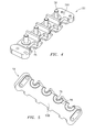
- the terminal assembly 54 generally includes a terminal board 56 which contains one or more terminal posts 58 and supports terminal connections 60 and passthroughs 62 (also illustrated in Figure 3 ).
- the terminal board 56 is mounted to the housing 50 through fasteners F such as bolts or the like which are threaded into the housing 50.
- the terminal board 56 and passthroughs 62 may be manufactured of a non-metallic material such as Torlon® Polyamide plastic while the terminal posts 58 and terminal connections 60 are manufactured of electrically conductive materials such as a steel alloy or copper alloy respectively.
- the terminal posts 58 extend from one side 56A ( Figure 4 ) of the terminal board 56 and the passthroughs 62 are engaged with an opposite side 56B ( Figure 5 ) of the terminal board 56.
- the terminal posts 58 are offset from the passthroughs 62 ( Figure 3 ). That is, the terminal posts 58 are defined along a first axis A and the passthroughs 62 are defined along a second axis B.
- the terminal connections 60 extend through the passthroughs 62 and are in electrical contact with the terminal posts 58.
- each passthrough 62 includes a generally annular body 63 with a first radially extending flange 64 and a second radially extending flange 66 ( Figure 6 ).
- the first radially extending flange 64 includes a stepped surface 68 ( Figure 7 ) between a first radially extending flange section 70 that is of a diameter greater than the second radially extending flange 66 and a second radially extending flange section 72 which is of a diameter generally equivalent to the second radially extending flange 66.
- the second radially extending flange section 72 and the second radially extending flange 66 are received within a bore 76 in the housing 50 such that the first radially extending flange section 70 covers a portion of the housing 50 and increase the creep path from the terminal connection 60 to the housing 50. That is, the first radially extending flange section 70 extends beyond the diameter of the bore 76.
- a first seal 80 such as an O-ring may be positioned around the passthrough 62 between the second radially extending flange section 72 and the second radially extending flange 66 provide a leak tight seal between the inside and outside of the generator housing 50 to contain oil therein.
- a second seal 82 such as an O-ring may also be positioned around a pin 84 of the terminal connection 60 and the passthrough 62 to facilitate the leak tight seal between the inside and outside of the generator housing 50.
- the pin 84 at terminal connection 60 may be a unitary component which is welded or otherwise fitted together.
- the terminal board 56 includes a multiple of interrupted apertures 78 ( Figures 4 and 5 ) which each receive the generally annular body 63 of the passthrough 62.
- the opposite side 56B of the terminal board 56 also includes an interface 86 which at least partially receives the first radially extending flange section 70.
- the interrupted apertures 78 are apertures having an interrupted periphery.
- the interface 86 in one disclosed non-limiting embodiment may include semi-circular recessed areas defined about the interrupted aperture 78 which receive each of the first radially extending flange sections 70 to further orient and restrain each passthrough 62 with respect to the terminal board 56.
- the passthroughs 62 disclosed herein increase clearance between conducting materials and also improve the physical shielding of the terminals to not only improve clearance performance but also improve creepage performance by lengthening or extending the path over the surface of the non-conducting material.
Landscapes
- Engineering & Computer Science (AREA)
- Power Engineering (AREA)
- Motor Or Generator Frames (AREA)
- Connector Housings Or Holding Contact Members (AREA)
- Coupling Device And Connection With Printed Circuit (AREA)
- Connections Arranged To Contact A Plurality Of Conductors (AREA)
Applications Claiming Priority (1)
| Application Number | Priority Date | Filing Date | Title |
|---|---|---|---|
| US13/043,835 US9337700B2 (en) | 2011-03-09 | 2011-03-09 | Terminal assembly with reduced creepage |
Publications (3)
| Publication Number | Publication Date |
|---|---|
| EP2498385A2 true EP2498385A2 (de) | 2012-09-12 |
| EP2498385A3 EP2498385A3 (de) | 2017-08-09 |
| EP2498385B1 EP2498385B1 (de) | 2020-05-06 |
Family
ID=45976079
Family Applications (1)
| Application Number | Title | Priority Date | Filing Date |
|---|---|---|---|
| EP12158682.0A Not-in-force EP2498385B1 (de) | 2011-03-09 | 2012-03-08 | Endanschlussklemmvorrichtung mit reduziertem Kriechen |
Country Status (3)
| Country | Link |
|---|---|
| US (1) | US9337700B2 (de) |
| EP (1) | EP2498385B1 (de) |
| CN (1) | CN102684362B (de) |
Families Citing this family (8)
| Publication number | Priority date | Publication date | Assignee | Title |
|---|---|---|---|---|
| US9472996B2 (en) * | 2013-04-15 | 2016-10-18 | Hamilton Sundstrand Corporation | Terminal assembly |
| JP6449694B2 (ja) * | 2015-03-18 | 2019-01-09 | 日立オートモティブシステムズ株式会社 | 電子制御装置 |
| JP2017189021A (ja) * | 2016-04-06 | 2017-10-12 | 株式会社日立産機システム | 端子台 |
| US10756459B2 (en) | 2017-07-31 | 2020-08-25 | Pentair Flow Technologies, Llc | Ring-style terminal block and submersible pump with ring-style terminal block |
| JP7229659B2 (ja) * | 2017-11-02 | 2023-02-28 | 住友重機械工業株式会社 | 動力伝達装置 |
| US11143286B2 (en) * | 2019-03-15 | 2021-10-12 | Hamilton Sundstrand Corporation | Differential unit gear shrouds |
| US11171429B2 (en) * | 2020-01-07 | 2021-11-09 | Hamilton Sundstrand Corporation | Terminal block assemblies |
| EP3985843A1 (de) * | 2020-10-16 | 2022-04-20 | Hamilton Sundstrand Corporation | Durchgangsisolator für generatoranschluss |
Family Cites Families (29)
| Publication number | Priority date | Publication date | Assignee | Title |
|---|---|---|---|---|
| US3045171A (en) | 1959-03-02 | 1962-07-17 | Westinghouse Electric Corp | Electrical control apparatus |
| US3808489A (en) | 1972-09-01 | 1974-04-30 | Gen Electric | Cooled flux shield for generator terminal box |
| US3899731A (en) | 1973-05-29 | 1975-08-12 | Electric Machinery Mfg Co | Voltage regulator with controlled current |
| DE2431958C3 (de) | 1974-07-03 | 1983-05-05 | Brown, Boveri & Cie Ag, 6800 Mannheim | Anordnung der Ständerstromanschlüsse für einen Turbogenerator großer Leistung |
| DE2557299C2 (de) | 1975-12-19 | 1983-12-15 | Brown, Boveri & Cie Ag, 6800 Mannheim | Anordnung der Ständerstromanschlüsse eines Turbogenerators großer Leistung |
| US4199700A (en) | 1978-07-31 | 1980-04-22 | Westinghouse Electric Corp. | Phase lead for connecting stator coils and parallel phase rings |
| US4254352A (en) | 1979-02-28 | 1981-03-03 | Westinghouse Electric Corp. | Parallel ring and ring extension support system for dynamoelectric machines |
| US4712029A (en) | 1986-12-22 | 1987-12-08 | Sundstrand Corporation | Generator high temperature electrical lead assembly |
| US5122696A (en) | 1991-03-13 | 1992-06-16 | General Electric Company | Main lead connector for a generator/motor rotor |
| US5358432A (en) | 1991-04-03 | 1994-10-25 | General Electric Company | Resilient connectors for a generator/motor rotor |
| US5227587A (en) * | 1991-05-13 | 1993-07-13 | Emerson Electric Co. | Hermetic assembly arrangement for a current conducting pin passing through a housing wall |
| US5489810A (en) | 1994-04-20 | 1996-02-06 | Sundstrand Corporation | Switched reluctance starter/generator |
| US5825109A (en) | 1994-11-30 | 1998-10-20 | Calumet Armature & Electric Co. | Vehicular oil cooled alternator with stator coil terminal assembly terminal assembly kit and method |
| US5949167A (en) | 1998-07-22 | 1999-09-07 | Reliance Electric Industrial Company | Lead wire routing and sealing assembly for large electric motor |
| US6264505B1 (en) * | 2000-03-01 | 2001-07-24 | Lockheed Martin Corporation | Integrated shielded cable |
| US6538339B2 (en) | 2000-03-02 | 2003-03-25 | Siemens Westinghouse Power Corporation | Power generation system interchangeability device and related methods |
| JP3551897B2 (ja) | 2000-06-09 | 2004-08-11 | 株式会社日立製作所 | 回転電機及び給電用リード線接続方法 |
| US6392323B1 (en) | 2000-08-31 | 2002-05-21 | Sanden Corporation | Protective covering for motor leads |
| US6424063B1 (en) | 2000-10-04 | 2002-07-23 | Siemens Westinghouse Power Corporation | Generator rotor lead path configuration |
| US6501201B1 (en) | 2000-10-04 | 2002-12-31 | Siemens Westinghouse Power Corporation | Generator rotor lead path configuration |
| JP3914399B2 (ja) * | 2001-06-12 | 2007-05-16 | 矢崎総業株式会社 | 電気接続箱の防水構造 |
| JP3909680B2 (ja) | 2002-04-25 | 2007-04-25 | 矢崎総業株式会社 | コネクタ構造 |
| US6897584B2 (en) * | 2002-04-25 | 2005-05-24 | Honeywell International Inc. | High power terminal block assembly for generators and method of assembling and installing the same |
| US6628024B1 (en) | 2002-07-30 | 2003-09-30 | Honeywell International, Inc. | Hermetically sealed feed-through assembly for gas turbine engine starter generators and related methods |
| US6906479B2 (en) * | 2002-08-06 | 2005-06-14 | Honeywell International, Inc. | Gas turbine engine starter generator with multiple windings on each exciter stator pole |
| JP4627712B2 (ja) | 2005-10-07 | 2011-02-09 | 株式会社日立製作所 | 回転電機及びその製作方法 |
| JP5103845B2 (ja) * | 2006-09-26 | 2012-12-19 | 日本電産株式会社 | レゾルバおよびモータ |
| US7527523B2 (en) * | 2007-05-02 | 2009-05-05 | Tyco Electronics Corporation | High power terminal block assembly |
| US20120133224A1 (en) * | 2010-11-29 | 2012-05-31 | Grosskopf Andrew P | Arc resistant terminal block |
-
2011
- 2011-03-09 US US13/043,835 patent/US9337700B2/en active Active
-
2012
- 2012-03-08 EP EP12158682.0A patent/EP2498385B1/de not_active Not-in-force
- 2012-03-09 CN CN201210060977.3A patent/CN102684362B/zh not_active Expired - Fee Related
Non-Patent Citations (1)
| Title |
|---|
| None |
Also Published As
| Publication number | Publication date |
|---|---|
| CN102684362B (zh) | 2016-08-10 |
| EP2498385B1 (de) | 2020-05-06 |
| US20120228970A1 (en) | 2012-09-13 |
| US9337700B2 (en) | 2016-05-10 |
| EP2498385A3 (de) | 2017-08-09 |
| CN102684362A (zh) | 2012-09-19 |
Similar Documents
| Publication | Publication Date | Title |
|---|---|---|
| EP2498385B1 (de) | Endanschlussklemmvorrichtung mit reduziertem Kriechen | |
| US9472996B2 (en) | Terminal assembly | |
| US6628024B1 (en) | Hermetically sealed feed-through assembly for gas turbine engine starter generators and related methods | |
| US7230363B2 (en) | Low profile generator configuration | |
| US8063522B2 (en) | Generator rotor ground bushing | |
| US20100320860A1 (en) | Crowned end winding support for main wound field of a generator | |
| US5006741A (en) | Brushless generator with concentrically arranged rectifier assembly | |
| US9369029B2 (en) | Rotating rectifier assembly for electric machine | |
| US9035507B2 (en) | Electric machine and rectifier assembly therefor | |
| EP2514074B1 (de) | Mutternsicherungsanordnung für einen stromgenerator | |
| US9490674B2 (en) | Rotating rectifier assembly for electric machine | |
| CN103682706A (zh) | 车用旋转电机 | |
| EP2793373A2 (de) | Anschlussleistenabdeckung | |
| US8143759B2 (en) | Laminated stator assembly | |
| US9343942B2 (en) | Rotating electrical machine for vehicle | |
| WO2011069801A1 (en) | An electrical machine | |
| CN108288879B (zh) | 用于电机的定子支承 | |
| EP2793372B1 (de) | Standrohranordnung | |
| US10224795B2 (en) | Motor assembly | |
| US20180172754A1 (en) | Rotating diode fault detection | |
| EP2506403A1 (de) | Wechselstromgenerator für ein fahrzeug | |
| CN113615048B (zh) | 旋转电机及其定子 | |
| JP2007312541A (ja) | 車両用交流発電機 |
Legal Events
| Date | Code | Title | Description |
|---|---|---|---|
| PUAI | Public reference made under article 153(3) epc to a published international application that has entered the european phase |
Free format text: ORIGINAL CODE: 0009012 |
|
| AK | Designated contracting states |
Kind code of ref document: A2 Designated state(s): AL AT BE BG CH CY CZ DE DK EE ES FI FR GB GR HR HU IE IS IT LI LT LU LV MC MK MT NL NO PL PT RO RS SE SI SK SM TR |
|
| AX | Request for extension of the european patent |
Extension state: BA ME |
|
| PUAL | Search report despatched |
Free format text: ORIGINAL CODE: 0009013 |
|
| AK | Designated contracting states |
Kind code of ref document: A3 Designated state(s): AL AT BE BG CH CY CZ DE DK EE ES FI FR GB GR HR HU IE IS IT LI LT LU LV MC MK MT NL NO PL PT RO RS SE SI SK SM TR |
|
| AX | Request for extension of the european patent |
Extension state: BA ME |
|
| RIC1 | Information provided on ipc code assigned before grant |
Ipc: H01R 13/52 20060101ALI20170704BHEP Ipc: H02K 5/22 20060101AFI20170704BHEP |
|
| STAA | Information on the status of an ep patent application or granted ep patent |
Free format text: STATUS: THE APPLICATION HAS BEEN PUBLISHED |
|
| STAA | Information on the status of an ep patent application or granted ep patent |
Free format text: STATUS: REQUEST FOR EXAMINATION WAS MADE |
|
| 17P | Request for examination filed |
Effective date: 20180530 |
|
| RBV | Designated contracting states (corrected) |
Designated state(s): AL AT BE BG CH CY CZ DE DK EE ES FI FR GB GR HR HU IE IS IT LI LT LU LV MC MK MT NL NO PL PT RO RS SE SI SK SM TR |
|
| STAA | Information on the status of an ep patent application or granted ep patent |
Free format text: STATUS: EXAMINATION IS IN PROGRESS |
|
| 17Q | First examination report despatched |
Effective date: 20190306 |
|
| GRAP | Despatch of communication of intention to grant a patent |
Free format text: ORIGINAL CODE: EPIDOSNIGR1 |
|
| STAA | Information on the status of an ep patent application or granted ep patent |
Free format text: STATUS: GRANT OF PATENT IS INTENDED |
|
| INTG | Intention to grant announced |
Effective date: 20191218 |
|
| RIN1 | Information on inventor provided before grant (corrected) |
Inventor name: PATEL, DHAVAL Inventor name: ALLEN, EDWARD C. Inventor name: VANEK, LAURENCE D. |
|
| GRAS | Grant fee paid |
Free format text: ORIGINAL CODE: EPIDOSNIGR3 |
|
| GRAA | (expected) grant |
Free format text: ORIGINAL CODE: 0009210 |
|
| STAA | Information on the status of an ep patent application or granted ep patent |
Free format text: STATUS: THE PATENT HAS BEEN GRANTED |
|
| AK | Designated contracting states |
Kind code of ref document: B1 Designated state(s): AL AT BE BG CH CY CZ DE DK EE ES FI FR GB GR HR HU IE IS IT LI LT LU LV MC MK MT NL NO PL PT RO RS SE SI SK SM TR |
|
| REG | Reference to a national code |
Ref country code: GB Ref legal event code: FG4D |
|
| REG | Reference to a national code |
Ref country code: CH Ref legal event code: EP Ref country code: AT Ref legal event code: REF Ref document number: 1268408 Country of ref document: AT Kind code of ref document: T Effective date: 20200515 |
|
| REG | Reference to a national code |
Ref country code: DE Ref legal event code: R096 Ref document number: 602012069810 Country of ref document: DE |
|
| REG | Reference to a national code |
Ref country code: IE Ref legal event code: FG4D |
|
| REG | Reference to a national code |
Ref country code: LT Ref legal event code: MG4D |
|
| REG | Reference to a national code |
Ref country code: NL Ref legal event code: MP Effective date: 20200506 |
|
| PG25 | Lapsed in a contracting state [announced via postgrant information from national office to epo] |
Ref country code: LT Free format text: LAPSE BECAUSE OF FAILURE TO SUBMIT A TRANSLATION OF THE DESCRIPTION OR TO PAY THE FEE WITHIN THE PRESCRIBED TIME-LIMIT Effective date: 20200506 Ref country code: GR Free format text: LAPSE BECAUSE OF FAILURE TO SUBMIT A TRANSLATION OF THE DESCRIPTION OR TO PAY THE FEE WITHIN THE PRESCRIBED TIME-LIMIT Effective date: 20200807 Ref country code: SE Free format text: LAPSE BECAUSE OF FAILURE TO SUBMIT A TRANSLATION OF THE DESCRIPTION OR TO PAY THE FEE WITHIN THE PRESCRIBED TIME-LIMIT Effective date: 20200506 Ref country code: NO Free format text: LAPSE BECAUSE OF FAILURE TO SUBMIT A TRANSLATION OF THE DESCRIPTION OR TO PAY THE FEE WITHIN THE PRESCRIBED TIME-LIMIT Effective date: 20200806 Ref country code: FI Free format text: LAPSE BECAUSE OF FAILURE TO SUBMIT A TRANSLATION OF THE DESCRIPTION OR TO PAY THE FEE WITHIN THE PRESCRIBED TIME-LIMIT Effective date: 20200506 Ref country code: IS Free format text: LAPSE BECAUSE OF FAILURE TO SUBMIT A TRANSLATION OF THE DESCRIPTION OR TO PAY THE FEE WITHIN THE PRESCRIBED TIME-LIMIT Effective date: 20200906 Ref country code: PT Free format text: LAPSE BECAUSE OF FAILURE TO SUBMIT A TRANSLATION OF THE DESCRIPTION OR TO PAY THE FEE WITHIN THE PRESCRIBED TIME-LIMIT Effective date: 20200907 |
|
| PG25 | Lapsed in a contracting state [announced via postgrant information from national office to epo] |
Ref country code: RS Free format text: LAPSE BECAUSE OF FAILURE TO SUBMIT A TRANSLATION OF THE DESCRIPTION OR TO PAY THE FEE WITHIN THE PRESCRIBED TIME-LIMIT Effective date: 20200506 Ref country code: HR Free format text: LAPSE BECAUSE OF FAILURE TO SUBMIT A TRANSLATION OF THE DESCRIPTION OR TO PAY THE FEE WITHIN THE PRESCRIBED TIME-LIMIT Effective date: 20200506 Ref country code: BG Free format text: LAPSE BECAUSE OF FAILURE TO SUBMIT A TRANSLATION OF THE DESCRIPTION OR TO PAY THE FEE WITHIN THE PRESCRIBED TIME-LIMIT Effective date: 20200806 Ref country code: LV Free format text: LAPSE BECAUSE OF FAILURE TO SUBMIT A TRANSLATION OF THE DESCRIPTION OR TO PAY THE FEE WITHIN THE PRESCRIBED TIME-LIMIT Effective date: 20200506 |
|
| REG | Reference to a national code |
Ref country code: AT Ref legal event code: MK05 Ref document number: 1268408 Country of ref document: AT Kind code of ref document: T Effective date: 20200506 |
|
| PG25 | Lapsed in a contracting state [announced via postgrant information from national office to epo] |
Ref country code: NL Free format text: LAPSE BECAUSE OF FAILURE TO SUBMIT A TRANSLATION OF THE DESCRIPTION OR TO PAY THE FEE WITHIN THE PRESCRIBED TIME-LIMIT Effective date: 20200506 Ref country code: AL Free format text: LAPSE BECAUSE OF FAILURE TO SUBMIT A TRANSLATION OF THE DESCRIPTION OR TO PAY THE FEE WITHIN THE PRESCRIBED TIME-LIMIT Effective date: 20200506 |
|
| PG25 | Lapsed in a contracting state [announced via postgrant information from national office to epo] |
Ref country code: IT Free format text: LAPSE BECAUSE OF FAILURE TO SUBMIT A TRANSLATION OF THE DESCRIPTION OR TO PAY THE FEE WITHIN THE PRESCRIBED TIME-LIMIT Effective date: 20200506 Ref country code: DK Free format text: LAPSE BECAUSE OF FAILURE TO SUBMIT A TRANSLATION OF THE DESCRIPTION OR TO PAY THE FEE WITHIN THE PRESCRIBED TIME-LIMIT Effective date: 20200506 Ref country code: EE Free format text: LAPSE BECAUSE OF FAILURE TO SUBMIT A TRANSLATION OF THE DESCRIPTION OR TO PAY THE FEE WITHIN THE PRESCRIBED TIME-LIMIT Effective date: 20200506 Ref country code: SM Free format text: LAPSE BECAUSE OF FAILURE TO SUBMIT A TRANSLATION OF THE DESCRIPTION OR TO PAY THE FEE WITHIN THE PRESCRIBED TIME-LIMIT Effective date: 20200506 Ref country code: AT Free format text: LAPSE BECAUSE OF FAILURE TO SUBMIT A TRANSLATION OF THE DESCRIPTION OR TO PAY THE FEE WITHIN THE PRESCRIBED TIME-LIMIT Effective date: 20200506 Ref country code: RO Free format text: LAPSE BECAUSE OF FAILURE TO SUBMIT A TRANSLATION OF THE DESCRIPTION OR TO PAY THE FEE WITHIN THE PRESCRIBED TIME-LIMIT Effective date: 20200506 Ref country code: CZ Free format text: LAPSE BECAUSE OF FAILURE TO SUBMIT A TRANSLATION OF THE DESCRIPTION OR TO PAY THE FEE WITHIN THE PRESCRIBED TIME-LIMIT Effective date: 20200506 Ref country code: ES Free format text: LAPSE BECAUSE OF FAILURE TO SUBMIT A TRANSLATION OF THE DESCRIPTION OR TO PAY THE FEE WITHIN THE PRESCRIBED TIME-LIMIT Effective date: 20200506 |
|
| REG | Reference to a national code |
Ref country code: DE Ref legal event code: R097 Ref document number: 602012069810 Country of ref document: DE |
|
| PG25 | Lapsed in a contracting state [announced via postgrant information from national office to epo] |
Ref country code: SK Free format text: LAPSE BECAUSE OF FAILURE TO SUBMIT A TRANSLATION OF THE DESCRIPTION OR TO PAY THE FEE WITHIN THE PRESCRIBED TIME-LIMIT Effective date: 20200506 Ref country code: PL Free format text: LAPSE BECAUSE OF FAILURE TO SUBMIT A TRANSLATION OF THE DESCRIPTION OR TO PAY THE FEE WITHIN THE PRESCRIBED TIME-LIMIT Effective date: 20200506 |
|
| PLBE | No opposition filed within time limit |
Free format text: ORIGINAL CODE: 0009261 |
|
| STAA | Information on the status of an ep patent application or granted ep patent |
Free format text: STATUS: NO OPPOSITION FILED WITHIN TIME LIMIT |
|
| 26N | No opposition filed |
Effective date: 20210209 |
|
| PG25 | Lapsed in a contracting state [announced via postgrant information from national office to epo] |
Ref country code: SI Free format text: LAPSE BECAUSE OF FAILURE TO SUBMIT A TRANSLATION OF THE DESCRIPTION OR TO PAY THE FEE WITHIN THE PRESCRIBED TIME-LIMIT Effective date: 20200506 |
|
| REG | Reference to a national code |
Ref country code: DE Ref legal event code: R119 Ref document number: 602012069810 Country of ref document: DE |
|
| PG25 | Lapsed in a contracting state [announced via postgrant information from national office to epo] |
Ref country code: MC Free format text: LAPSE BECAUSE OF FAILURE TO SUBMIT A TRANSLATION OF THE DESCRIPTION OR TO PAY THE FEE WITHIN THE PRESCRIBED TIME-LIMIT Effective date: 20200506 |
|
| REG | Reference to a national code |
Ref country code: CH Ref legal event code: PL |
|
| REG | Reference to a national code |
Ref country code: BE Ref legal event code: MM Effective date: 20210331 |
|
| PG25 | Lapsed in a contracting state [announced via postgrant information from national office to epo] |
Ref country code: CH Free format text: LAPSE BECAUSE OF NON-PAYMENT OF DUE FEES Effective date: 20210331 Ref country code: LI Free format text: LAPSE BECAUSE OF NON-PAYMENT OF DUE FEES Effective date: 20210331 Ref country code: LU Free format text: LAPSE BECAUSE OF NON-PAYMENT OF DUE FEES Effective date: 20210308 Ref country code: IE Free format text: LAPSE BECAUSE OF NON-PAYMENT OF DUE FEES Effective date: 20210308 Ref country code: DE Free format text: LAPSE BECAUSE OF NON-PAYMENT OF DUE FEES Effective date: 20211001 |
|
| PG25 | Lapsed in a contracting state [announced via postgrant information from national office to epo] |
Ref country code: BE Free format text: LAPSE BECAUSE OF NON-PAYMENT OF DUE FEES Effective date: 20210331 |
|
| PGFP | Annual fee paid to national office [announced via postgrant information from national office to epo] |
Ref country code: FR Payment date: 20230222 Year of fee payment: 12 |
|
| PG25 | Lapsed in a contracting state [announced via postgrant information from national office to epo] |
Ref country code: HU Free format text: LAPSE BECAUSE OF FAILURE TO SUBMIT A TRANSLATION OF THE DESCRIPTION OR TO PAY THE FEE WITHIN THE PRESCRIBED TIME-LIMIT; INVALID AB INITIO Effective date: 20120308 Ref country code: CY Free format text: LAPSE BECAUSE OF FAILURE TO SUBMIT A TRANSLATION OF THE DESCRIPTION OR TO PAY THE FEE WITHIN THE PRESCRIBED TIME-LIMIT Effective date: 20200506 |
|
| PGFP | Annual fee paid to national office [announced via postgrant information from national office to epo] |
Ref country code: GB Payment date: 20230222 Year of fee payment: 12 |
|
| P01 | Opt-out of the competence of the unified patent court (upc) registered |
Effective date: 20230522 |
|
| PG25 | Lapsed in a contracting state [announced via postgrant information from national office to epo] |
Ref country code: MK Free format text: LAPSE BECAUSE OF FAILURE TO SUBMIT A TRANSLATION OF THE DESCRIPTION OR TO PAY THE FEE WITHIN THE PRESCRIBED TIME-LIMIT Effective date: 20200506 |
|
| PG25 | Lapsed in a contracting state [announced via postgrant information from national office to epo] |
Ref country code: TR Free format text: LAPSE BECAUSE OF FAILURE TO SUBMIT A TRANSLATION OF THE DESCRIPTION OR TO PAY THE FEE WITHIN THE PRESCRIBED TIME-LIMIT Effective date: 20200506 |
|
| PG25 | Lapsed in a contracting state [announced via postgrant information from national office to epo] |
Ref country code: MT Free format text: LAPSE BECAUSE OF FAILURE TO SUBMIT A TRANSLATION OF THE DESCRIPTION OR TO PAY THE FEE WITHIN THE PRESCRIBED TIME-LIMIT Effective date: 20200506 |
|
| GBPC | Gb: european patent ceased through non-payment of renewal fee |
Effective date: 20240308 |
|
| PG25 | Lapsed in a contracting state [announced via postgrant information from national office to epo] |
Ref country code: GB Free format text: LAPSE BECAUSE OF NON-PAYMENT OF DUE FEES Effective date: 20240308 |
|
| PG25 | Lapsed in a contracting state [announced via postgrant information from national office to epo] |
Ref country code: FR Free format text: LAPSE BECAUSE OF NON-PAYMENT OF DUE FEES Effective date: 20240331 |
|
| PG25 | Lapsed in a contracting state [announced via postgrant information from national office to epo] |
Ref country code: GB Free format text: LAPSE BECAUSE OF NON-PAYMENT OF DUE FEES Effective date: 20240308 Ref country code: FR Free format text: LAPSE BECAUSE OF NON-PAYMENT OF DUE FEES Effective date: 20240331 |