EP2498448A1 - Système, procédé et appareil de détermination de la consommation en puissance dans un compteur de service - Google Patents
Système, procédé et appareil de détermination de la consommation en puissance dans un compteur de service Download PDFInfo
- Publication number
- EP2498448A1 EP2498448A1 EP12158323A EP12158323A EP2498448A1 EP 2498448 A1 EP2498448 A1 EP 2498448A1 EP 12158323 A EP12158323 A EP 12158323A EP 12158323 A EP12158323 A EP 12158323A EP 2498448 A1 EP2498448 A1 EP 2498448A1
- Authority
- EP
- European Patent Office
- Prior art keywords
- customer
- utility meter
- information
- han
- area network
- Prior art date
- Legal status (The legal status is an assumption and is not a legal conclusion. Google has not performed a legal analysis and makes no representation as to the accuracy of the status listed.)
- Withdrawn
Links
Images

Classifications
-
- H—ELECTRICITY
- H04—ELECTRIC COMMUNICATION TECHNIQUE
- H04L—TRANSMISSION OF DIGITAL INFORMATION, e.g. TELEGRAPHIC COMMUNICATION
- H04L12/00—Data switching networks
- H04L12/28—Data switching networks characterised by path configuration, e.g. LAN [Local Area Networks] or WAN [Wide Area Networks]
- H04L12/2803—Home automation networks
- H04L12/2823—Reporting information sensed by appliance or service execution status of appliance services in a home automation network
- H04L12/2827—Reporting to a device within the home network; wherein the reception of the information reported automatically triggers the execution of a home appliance functionality
-
- G—PHYSICS
- G01—MEASURING; TESTING
- G01D—MEASURING NOT SPECIALLY ADAPTED FOR A SPECIFIC VARIABLE; ARRANGEMENTS FOR MEASURING TWO OR MORE VARIABLES NOT COVERED IN A SINGLE OTHER SUBCLASS; TARIFF METERING APPARATUS; MEASURING OR TESTING NOT OTHERWISE PROVIDED FOR
- G01D4/00—Tariff metering apparatus
- G01D4/02—Details
-
- G—PHYSICS
- G01—MEASURING; TESTING
- G01D—MEASURING NOT SPECIALLY ADAPTED FOR A SPECIFIC VARIABLE; ARRANGEMENTS FOR MEASURING TWO OR MORE VARIABLES NOT COVERED IN A SINGLE OTHER SUBCLASS; TARIFF METERING APPARATUS; MEASURING OR TESTING NOT OTHERWISE PROVIDED FOR
- G01D2204/00—Indexing scheme relating to details of tariff-metering apparatus
- G01D2204/10—Analysing; Displaying
- G01D2204/14—Displaying of utility usage with respect to time, e.g. for monitoring evolution of usage or with respect to weather conditions
-
- H—ELECTRICITY
- H04—ELECTRIC COMMUNICATION TECHNIQUE
- H04L—TRANSMISSION OF DIGITAL INFORMATION, e.g. TELEGRAPHIC COMMUNICATION
- H04L12/00—Data switching networks
- H04L12/02—Details
- H04L12/14—Charging, metering or billing arrangements specially adapted for data communications, e.g. authentication, authorisation and accounting [AAA] framework
-
- Y—GENERAL TAGGING OF NEW TECHNOLOGICAL DEVELOPMENTS; GENERAL TAGGING OF CROSS-SECTIONAL TECHNOLOGIES SPANNING OVER SEVERAL SECTIONS OF THE IPC; TECHNICAL SUBJECTS COVERED BY FORMER USPC CROSS-REFERENCE ART COLLECTIONS [XRACs] AND DIGESTS
- Y02—TECHNOLOGIES OR APPLICATIONS FOR MITIGATION OR ADAPTATION AGAINST CLIMATE CHANGE
- Y02B—CLIMATE CHANGE MITIGATION TECHNOLOGIES RELATED TO BUILDINGS, e.g. HOUSING, HOUSE APPLIANCES OR RELATED END-USER APPLICATIONS
- Y02B90/00—Enabling technologies or technologies with a potential or indirect contribution to GHG emissions mitigation
- Y02B90/20—Smart grids as enabling technology in buildings sector
-
- Y—GENERAL TAGGING OF NEW TECHNOLOGICAL DEVELOPMENTS; GENERAL TAGGING OF CROSS-SECTIONAL TECHNOLOGIES SPANNING OVER SEVERAL SECTIONS OF THE IPC; TECHNICAL SUBJECTS COVERED BY FORMER USPC CROSS-REFERENCE ART COLLECTIONS [XRACs] AND DIGESTS
- Y04—INFORMATION OR COMMUNICATION TECHNOLOGIES HAVING AN IMPACT ON OTHER TECHNOLOGY AREAS
- Y04S—SYSTEMS INTEGRATING TECHNOLOGIES RELATED TO POWER NETWORK OPERATION, COMMUNICATION OR INFORMATION TECHNOLOGIES FOR IMPROVING THE ELECTRICAL POWER GENERATION, TRANSMISSION, DISTRIBUTION, MANAGEMENT OR USAGE, i.e. SMART GRIDS
- Y04S20/00—Management or operation of end-user stationary applications or the last stages of power distribution; Controlling, monitoring or operating thereof
- Y04S20/30—Smart metering, e.g. specially adapted for remote reading
Definitions
- Embodiments of the invention relate generally to utility meters, and more particularly, to systems, methods, and apparatuses for determining power usage within a meter.
- a smart utility meter system there may be a plurality of devices such as home network devices in communication with a utility meter.
- the owner of the utility meter such as a utility company is responsible for covering the power consumption of radios utilized for communicating with network devices, including home network devices.
- network devices including home network devices.
- the owner of the utility meter such as a utility company may be interested in charging back at least a portion of the power consumption of the radios to customers. Accordingly, there is an opportunity for systems, methods, and apparatuses for determining power usage within a meter.
- Embodiments of the invention may include systems, methods, and apparatuses for determining power usage within a meter.
- a utility meter apparatus including at least one communications interface for communicating with a home area network (HAN); and at least one processor in communication with the at least one communications interface.
- the at least one processor may be configured to: receive or transmit, via the at least one communications interface, information having a source or destination associated with the home area network (HAN); determine that the information is attributable to activity chargeable to a customer associated with the home area network (HAN); and update a customer usage amount based upon the determination that the information is attributable to the activity chargeable to the customer.
- a method including providing, for a utility meter, at least one communications interface for communicating with a home area network (HAN); receiving or transmitting, via the at least one communications interface of the utility meter, information having a source or destination associated with the home area network (HAN); determining, by the utility meter, that the information is attributable to activity chargeable to a customer associated with the home area network (HAN); and updating, by the utility meter, a customer usage amount based upon the determination that the information is attributable to the activity chargeable to the customer.
- HAN home area network
- a system including a server computer; and a plurality of utility meters in communication with the server computer, each utility meter as described above.
- a smart utility meter may be in communication with one or more network devices (e.g., home devices and other devices) via a home area network / local area network, as described herein.
- a smart utility meter in accordance with an example embodiment of the invention may determine whether information received from or destined to a network device is a result of activity chargeable to a customer. If the information received from or destined to a network device is a result of activity chargeable to a customer, then a customer usage amount may be updated to reflect power usage associated with receiving information from or transmitting information to a network device. If desired by a utility company or an owner of the utility meter, a customer may be charged for at least a portion of the customer usage amount, according to an example embodiment of the invention.
- a smart utility meter in accordance with an example embodiment of the invention can analyze the information received from or destined to a network device to determine whether it is a result of activity chargeable to the customer. For example, the information can be analyzed to determine the message type or a unique identifier (e.g., Media Access Control (MAC) address, Internet Protocol (IP) address, or other network address etc.) associated with the source or destination of the information.
- MAC Media Access Control
- IP Internet Protocol
- certain message types can be associated with activity chargeable to the customer.
- information from or to certain network device addresses can also be associated with activity chargeable to the customer.
- Various embodiments of the invention may include one or more special purpose computers, systems, and/or particular machines that facilitate the network communications with one or more smart utility meters and/or other network devices.
- a special purpose computer or particular machine may include a wide variety of different software modules as desired in various embodiments. As explained in greater detail below, in certain embodiments, these various software components may be utilized to facilitate communications between one or more network devices and one or more smart utility meters. Additionally, these various software components may be utilized to support determining power usage within a meter.
- Certain embodiments of the invention described herein may have the technical effect of a utility meter determining power consumption by radios or other communications interfaces of the utility meter. For example, power consumption of radios or communications interfaces based upon activity chargeable to the customer may be determined and/or accumulated. In this way, power consumption by radios or communications interfaces can be allocated or apportioned based upon activity chargeable to the customer.
- FIG. 1 is a block diagram of one example utility metering system 100 that supports determining power usage within a meter, according to an illustrative embodiment of the invention.
- the system 100 illustrated in FIG. 1 may include a plurality of smart utility meters 105a-n, according to an example embodiment of the invention.
- Each smart utility meter 105a-n may be in communication with one or more home area networks (HANs) or local area networks (LANs) 110a-n using wired communications (e.g., power line carrier communications, serial communications link, USB, Ethernet, fiber optic, etc.) or wireless communications (e.g., Zigbee, Global System for Mobile Communications (GSM), Wi-Fi, Worldwide Interoperability for Microwave Access (WiMAX), General Packet Radio Service (GPRS), Bluetooth, cellular, 3G, 4G, 802.11x, radio frequency (RF) mesh communications, etc.).
- GSM Global System for Mobile Communications
- WiMAX Worldwide Interoperability for Microwave Access
- GPRS General Packet Radio Service
- Bluetooth Bluetooth
- RF radio frequency mesh communications
- Each HAN / LAN 110a-n may include or be in communication with one or more network devices, which may include one or more home devices such as lights, appliances (e.g., refrigerator, stove, oven, dishwasher, clothes washer, clothes dryer, coffee maker, etc.), televisions, security systems, air conditioning and/or heating units, home Internet modems and routers, and the like, according to an example embodiment of the invention.
- utility meter 105a can communicate with one or more network devices 111a-n via HAN / LAN 110a.
- utility meter 105b can communicate with one or more network devices 112a-n via HAN / LAN 110b.
- Utility meter 105c can communicate with one or more network devices 113a-n via HAN / LAN 110c.
- utility meter 105n can communicate with one or more network devices 114a-n via HAN / LAN 110n. It will be appreciated that one or more of the network devices 111a-n, 112a-n, 113a-n, 114a-n may receive a metered commodity (e.g., electricity, water, gas, etc.) via a respective utility meter 105a-n.
- a metered commodity e.g., electricity, water, gas, etc.
- each smart utility meter 105a-n may be in further communication with one or more neighborhood area networks (NANs) 115a-n via wired or wireless communications similar to those described herein.
- NANs neighborhood area networks
- These NANs 115a-n may provide further connectivity to other NANs and wide area networks (WANs) 125 (e.g., the Internet, a cellular network, a satellite-based network, etc.) via one or more gateway computers 120a-n.
- WANs wide area networks
- These NANs 115a-n and/or WANs 125 can enable communications between or among utility meters 105a-n, utility server computers 130, and/or one or more other computers associated with a utility company.
- the NANs 115 and/or WAN 125 can be provided or accessed via wired and/or wireless communications, and collectively create an interconnected network.
- a utility meter 105a-n can communicate with a utility server computer 130 via a gateway computer 120a-n and/or WAN 125.
- the WAN 125, gateway computers 120a-n, and the NANs 115a-n may be part of a same network such as the Internet.
- the utility meter 105a-n may also be in communication with a WAN 125 or other networks without an intermediate NAN 115a-n.
- HANs / LANs 110a-n may be available via the various combinations of HANs / LANs 110a-n, NANs 115a-n, gateway computers 120a-n, and WAN 125.
- utility server computer 130 or other computers / processors associated with the utility company or another entity may communicate with various utility meters 105a-n through direct or indirect routes involving various combinations of WAN 125, gateway computers 120a-n, and other utility meters 105an.
- utility server computer 130 could communicate with utility meter 105b, HAN / LAN 110b, and/or any devices 112a-n associated with HAN / LAN 110b using any combination of WAN 125, gateway computers 120a-n, and any other utility meters 105a, 105c, and/or 105n. Accordingly, in some example embodiments of the invention, utility meters 105a-n and HANs / LANs 110a-n can communicate with other network devices in performing certain routing or retransmission functionality, according to an example embodiment of the invention.
- a utility meter 105a-n may be any suitable utility meter that may be connected to a commodity metering and distribution system, such as an electrical meter connected to a power distribution grid that includes any number of power lines.
- a wide variety of suitable electrical meters may be utilized as desired in various embodiments, such as a single-phase meter or a three-phase meter.
- a utility meter 105a-n may be configured to measure an amount of electrical energy (e.g., kilowatt hours, etc.) or electrical power that is supplied to an associated location, residence, business, household, or machine.
- the utility meter 105 can also be associated with the metering and distribution of commodities other than electricity such as water, gas, and the like.
- the utility meter 105a-n may be configured to meter and supply or distribute commodities to an associated location, residence, business, household, or machine, including an associated network device 111a-n, 112a-n, 113a-n, 114a-n.
- the utility meter 105a-n may be a smart meter or an advanced meter that is configured to identify commodity consumption in relatively greater detail than a conventional meter.
- a smart utility meter 105a-n may facilitate real-time or near real-time readings, commodity outage notifications, and/or commodity quality monitoring.
- a smart utility meter 105a-n may communicate measurements data, calculations, and/or other information to one or more recipients, such as a utility server computer 130 of a utility company or a smart meter data processing system.
- a smart utility meter 105a-n may be configured to determine power usage when processing or communicating information with one or more devices 111a-n, 112a-n, 113a-n, or 114a-n, according to an example embodiment of the invention.
- embodiments of the invention may include a system 100 with more or less than the components illustrated in FIG. 1 . Additionally, certain components of the system 100 may be combined or omitted in various embodiments of the invention.
- the system 100 of FIG. 1 is provided by way of example only, as appreciated by those of ordinary skill in the art.
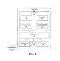
- FIG. 2 illustrates an example utility meter 205, according to an example embodiment of the invention.
- the utility meter 205 of FIG. 2 may be an example implementation of any one of the utility meters 105a-n of FIG. 1 .
- an example utility meter 205 may include any number of suitable computer processing components that facilitate the operation of the utility meter and/or the provision of a utility service and/or commodity (e.g., electricity, water, gas, etc.) to a location, including a customer home location.
- suitable processing devices that may be incorporated into a utility meter 205 include, but are not limited to, application-specific circuits, microcontrollers, minicomputers, other computing devices, and the like.
- a utility meter 205 may include any number of processors 232 that facilitate the execution of computer-readable instructions. By executing computer-readable instructions, the utility meter 205 may include or form a special purpose computer or particular machine that facilitates the provision of a utility service and/or the provision of a commodity to a location.
- the utility meter 205 may include one or more memory devices 234 and/or one or more network and/or communications interfaces 236.
- the one or more memory devices 234 or memories may include any suitable memory devices, for example, caches, read-only memory devices, random access memory devices, magnetic storage devices, etc.
- the one or more memory devices 234 may store data, executable instructions, and/or various program modules utilized by the utility meter 205, for example, data files 238, an operating system (“OS") 240, a metering module 242, and/or a central monitoring system module 243.
- OS operating system
- the data files 238 may include, for example, stored data associated with the operation of a utility meter 205, stored data associated with measurements and/or readings taken by the utility meter 205, utility meter configuration information, stored requests, messages and/or alerts, and/or stored commodity management, usage, and/or distribution data.
- the data files 238 can further include information supporting determining power usage within a meter.
- the data files 238 may include identification of message or information types that are known to be chargeable and/or non-chargeable (or attributable / non-attributable) to customers.
- the data files 238 can also include unique identifiers or other identifiers (e.g., MAC address, IP address, or other network address) known to transmit or receive information or messages that are known to be chargeable and/or non-chargeable (or attributable / non-attributable) to customers.
- the data files 238 can maintain a MAC address or IP address for home network devices that are known to transmit information or messages to a utility meter 205, or receive information from a utility meter 205, in performing an activity that is chargeable to a customer.
- the data files 238 can also store identification information for one or more services that are changeable to a customer. Many other types of information can be stored in data files 238 without departing from example embodiments of the invention.
- the OS 240 may include executable instructions and/or program modules that facilitate and/or control the general operation of the utility meter 205.
- the OS 240 may facilitate the execution of other software programs and/or program modules by the processors 232.
- the central monitoring system module 243 may be configured to identify when communications are being performed with one or more home network devices in accordance with activity chargeable to a customer, and to determine, perhaps using a sensor 245, the associated power consumption associated with such communications (e.g., power consumption by a radio or network/communications interface 236).
- the one or more network communications interfaces 236 associated with the utility meter 205 can include a HAN / LAN interface and a NAN interface.
- the LAN interface can be used for communicating or connecting with one or more HANs / LANs such as HANs / LANs 110a-n of FIG. 1
- the NAN interface can be used for communicating or connecting with one or more NANs such as NANs 115a-n of FIG. 1 .
- a utility meter 205 may receive data from and/or communicate data to other components of the system 100.
- wired interfaces e.g., power line carrier communications, serial communications link, USB, Ethernet, fiber optic, etc.
- wireless interfaces e.g., ZigBee, GSM, Wi-Fi, WiMAX, Bluetooth, GRPS,
- one or more sensors 245 may be in communication with transceiver(s) 237 / network/communications interface 236 (e.g., radios) for determining power consumption associated with communicating with a network device in accordance with activity chargeable to a customer.
- transceiver(s) 237 e.g., radios
- the utility meter 205 may typically receive a commodity from a connected commodity line, grid and/or source, and likewise meter and distribute the commodity to an associated location, residence, business, household, or machine, including an associated network device 111a-n, 112a-n, 113a-n, 114a-n. Additionally, as desired in certain embodiments, the utility meter 205 may include any number of suitable power sources 244, which can include wired power supplies and solar power cells, as well as back-up power supplies such as one or more batteries, fuel cells, or one or more super capacitors.
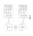
- FIG. 3 illustrates an example implementation for HANs / LANs that are in communication with respective utility meters, according to an example embodiment of the invention.
- there may be utility meter A 105a in communication with HAN / LAN A 110a, as well as a utility meter B 105b in communication with HAN / LAN B 110b.
- the utility meter A 105a and the utility meter B 105b may be in communication with one or more NANs, including NAN 115a or alternatively, other NANs 115b-n or WANs, according to an example embodiment of the invention.
- one or more of network devices 111a-n in HAN / LAN A 110a may communicate with the utility meter A 105a via power line carrier (PLC) communications or other wired communications.
- PLC power line carrier
- An access node 310 may be in the form of a repeater, gateway, aggregator, router, or one of the devices 111a-n, without departing from example embodiments of the invention.
- one or more devices 112a-n in HAN / LAN B 110b may communicate with the utility meter B 105b via radio frequency (RF) or other wireless communications.
- RF radio frequency
- An access node 320 may be in the form of a repeater, gateway, aggregator, router, or one of the devices 112a-n, without departing from example embodiments of the invention.
- HANs / LANs 110a, 110b can utilize a combination of communications via wired and wireless communication.
- a first portion of devices 111a-n may communicate with access node 310 / utility meter A 105a via wired or PLC communications, while a second portion of devices 111a-n may communicate with access node 310 / utility meter A 105a via RF or wireless communications.
- HANs / LANs 110a, 110b may be heterogeneous networks supporting device communications via various communications mediums and various communications protocols.
- the example utility meters 105a, 105b may be in communication with one or more respective network devices 111a-n or 112a-n, which when located in, near, or around a customer home, can be referred to as a home device.
- These network devices 111a-n, 112a-n may include lights, appliances (e.g., refrigerator, stove, oven, dishwasher, clothes washer, clothes dryer, coffee maker, etc.), televisions, security systems, air conditioning and/or heating units, sprinkler systems, home Internet modems and routers.
- network devices 111a-n can also be located outside of a customer home or location, and can communicate with the example utility meter using wired or wireless communications without departing from example embodiments of the invention.
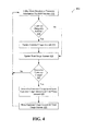
- FIG. 4 illustrates an example flow diagram of a method for determining power usage within a utility meter, according to an example embodiment of the invention.
- the operations of the method 400 may be performed by a utility meter, such as the example utility meter 205 of FIG. 2 .
- the operations of the method 400 may be implemented as computer-executable instructions stored in memory 234 and executed by a processor 232.
- the example utility meter 205 of FIG. 2 is representative of any of the utility meters 105a-n of FIG. 1 (or FIG. 3 ), it will be appreciated that the operations of the method 400 of FIG. 4 can likewise be performed by any of the utility meters 105a-n, or other utility meters in accordance with embodiments of the invention.
- each utility meter 105a, 105b may include one or more components of the example utility meter 205 of FIG. 2 .
- a utility meter 105a, 105b may receive or transmit a packet, frame, or other information via its respective network / communications interface 236 for respective HAN / LAN 110a, 110b, according to an example embodiment of the invention.
- the packet, frame, or other information may have a source or destination associated with a HAN / LAN 110a, 110b. Indeed, the packet, frame, or other information may be received from or transmitted to one or more respective network devices 111a-n, 112a-n (e.g., home devices) within HAN / LAN 110a, 110b.
- a power consumption sensor 245 may be enabled or otherwise utilized to determine the power consumption of the associated network/communications interface 236 (e.g., radio) when transmitting or receiving the packet, frame, or other information.
- a timer could also be used to record or determine the amount of time utilized by the network/communications interface 236 (e.g., radio) during transmission or receipt of the packet, frame, or other information.
- block 405 may generally determine a consumption amount, whether in units of power, time, or otherwise, utilized by the network/communications interface 236 when communicating with respective network devices 111a-n, 112a-n (e.g., home devices) within HAN / LAN 110a, 110b.
- network devices 111a-n, 112a-n e.g., home devices
- a utility meter 105a, 105b may determine whether the packet, frame, or other information is attributable to activity chargeable to a customer associated with the HAN / LAN 110a or 110b.
- Example activity that may be chargeable to a customer may include:
- a network device e.g., home device
- another network device e.g., home device
- a network device may communicate with another network device for purposes of configuration, coordination of operation, power management, and the like.
- a meter Communications between a meter and network devices (e.g., home devices) such as appliances, displays, and load devices.
- network devices e.g., home devices
- appliances e.g., displays, and load devices.
- a HAN / LAN may be a mesh network, any customer traffic that is repeated through the meter to another customer device.
- Activity of a HAN / LAN communications interface in a meter for packets destined for a network device (e.g., home device) in the HAN / LAN For example, a HAN / LAN communications interface (e.g., HAN radio or PLC modem) of a meter may wake up from a stand-by state to determine where a packet or other information is destined for. Packets or other information that cause the HAN / LAN communications interface to wake up, but ultimately are not bound for the meter may be charged to the customer.
- a network device e.g., home device
- PLC modem Packets or other information that cause the HAN / LAN communications interface to wake up, but ultimately are not bound for the meter may be charged to the customer.
- a network device in the HAN / LAN requesting information from the utility meter, or transmitting information to the utility meter.
- a network device may request optional updates or configuration information.
- block 410 may determine whether the packet, frame, or other information is attributable to activity chargeable to the customer based at least in part on a unique address or network address, including the source address and/or destination address, included or associated with the packet, frame, or other information.
- a packet, frame, or other information can be determined to be associated with a network device (e.g., home device) in the HAN / LAN communicating with another home device in the HAN / LAN based upon the source and destination addresses of the packet, frame, or other information being associated with network devices in a HAN / LAN, according to an example embodiment of the invention.
- a network device e.g., home device
- a respective list of network devices may be maintained by respective utility meters 105a, 105b for purposes of identifying respective network devices 111a-n, 112a-n in respective HANs / LANs 110a, 110b.
- a bit or other information can be included (or set to a particular value) in the packet, frame, or other information to designate activity chargeable to the customer or utility, according to an example embodiment of the invention.
- processing may proceed to block 415 so that the customer usage amount can be updated.
- the current customer usage amount may be updated from a prior value to reflect the determined power consumption at block 405 when the associated network / communications interface 236 (e.g., radio) is in operation or is processing.
- the current customer usage amount may be updated by adding the power consumption determined at block 405 to a prior value of the customer usage amount.
- the current customer usage amount may be stored in an appropriate unit of power measurement such as watts, watt-hours, and the like.
- the current customer usage amount may be reflective of a unit of time instead of a unit of power measurement.
- the current customer usage amount may be updated at block 410 by adding the time consumption determined at block 405 to a prior time value of the customer usage amount.
- the total usage amount may likewise be updated to reflect the power consumption determined at block 405.
- the total usage amount may reflect the power consumed by the network / communications interface 236 (e.g., radio) when a utility meter 105a, 105b communicates with respective network devices 111a-n, 112a-n (e.g., home devices) within HAN / LAN 110a, 110b, irrespective of whether the activity is attributable or not attributable to customer-chargeable activity, according to an example embodiment of the invention.
- the total usage amount may be updated at block 420 by adding the time consumption determined at block 405 to a prior time value of the total usage amount.
- network / communications interface 236 e.g., radio
- block 410 could also determine that the packet, frame, or other information is not attributable to activity chargeable to a customer, and processing may proceed directly to block 420.
- the total usage amount may likewise be updated to reflect the power consumption (or alternatively, time consumption) determined at block 405.
- the total usage amount is updated at block 420 without updating the customer usage amount at block 415 since the activity requiring operating of the network / communications interface 236 (e.g., radio) is not chargeable to a customer.
- block 425 a determination may be made as to whether a customer charge should be determined for billing, invoicing, or other allocating. For example, block 425 may be invoked periodically (e.g., once every week, once every month, once every two months, etc.) or upon a request received by a utility meter 105a, 105b from a utility server computer 130. If no customer charge is to be determined based upon block 425, then processing may return to block 405, as described above, where the customer usage amount and/or total usage amount can continue to be updated. It will also be appreciated that a time or time range of the consumption may likewise be recorded, which may facilitate demand-based pricing or tiered pricing based upon the time of day, according to an example embodiment of the invention.
- the utility meter 105a, 105b can facilitate the determination of the customer charge amount based upon the customer-chargeable activity. For example, the utility meter 105a, 105b can deliver the customer usage amount and the total usage amount to the utility server computer 130. The utility server computer 130 can then determine customer charge amount. For example, the utility server computer 130 can calculate a total amount due by the customer based upon the customer usage amount alone. For example, if the customer usage amount is provided in a unit of power consumption, such as watts or watt-hours, then the customer usage amount can be combined (e.g., multiplied) with a cost per watt or watt-hour.
- a unit of power consumption such as watts or watt-hours
- demand-based pricing or tiered pricing may be utilized to determine the customer charge amount.
- rate X for usage during period A, and rate Y for usage during period B may be utilized to determine the customer charge amount.
- recorded time information may be available for the customer usage amount, where the time information enables allocating the customer usage amount to one or more time periods during a day (e.g., certain ranges within a 24 hour period).
- the utility server computer 130 can also calculate a ratio of the customer usage amount and the total usage amount (e.g., a ratio based upon power consumption or time consumption).
- the calculated ratio can then be combined (e.g., multiplied) with an estimated / actual power usage amount or cost for operation of a respective network / communications interface 236 (e.g., radio) by a respective utility meter 105a, 105b to calculate a customer-chargeable power usage amount or chargeable monetary amount. If a chargeable power usage amount is determined, it can be combined or multiplied with a cost per power usage amount to derive a customer-chargeable monetary amount. It will be appreciated that these calculations being performed by the utility server computer 130 could also be performed by the utility meter 105a, 105b, with the results of the calculations being transmitted to the utility server computer 130, according to an example embodiment of the invention. Accordingly, the total chargeable amount due by the customer can then be recovered, for example, by billing the customer for the usage, or by adding the amount to the customer's bill from a utility company, according to an example embodiment of the invention.
- block 435 the utility meter 105a, 105b can then reset the customer usage amount and the total usage amount so that the total amount due by the customer can be determined for another time period.
- block 435 may not necessarily need to reset the customer usage amount and the total usage amount if the prior values utilized for prior time periods are maintained, according to an example embodiment of the invention.
- FIG. 4 It will be appreciated that many variations of FIG. 4 are available without departing from example embodiments of the invention.
- These computer-executable program instructions may be loaded onto a general purpose computer, a special-purpose computer, a processor, or other programmable data processing apparatus to produce a particular machine, such that the instructions that execute on the computer, processor, or other programmable data processing apparatus create means for implementing one or more functions specified in the flow diagram block or blocks.
- These computer program instructions may also be stored in a computer-readable memory that can direct a computer or other programmable data processing apparatus to function in a particular manner, such that the instructions stored in the computer-readable memory produce an article of manufacture including instruction means that implement one or more functions specified in the flow diagram block or blocks.
- embodiments of the invention may provide for a computer program product, comprising a computer-usable medium having a computer- readable program code or program instructions embodied therein, said computer-readable program code adapted to be executed to implement one or more functions specified in the flow diagram block or blocks.
- the computer program instructions may also be loaded onto a computer or other programmable data processing apparatus to cause a series of operational elements or steps to be performed on the computer or other programmable apparatus to produce a computer-implemented process such that the instructions that execute on the computer or other programmable apparatus provide elements or steps for implementing the functions specified in the flow diagram block or blocks.
- blocks of the block diagrams and flow diagrams support combinations of means for performing the specified functions, combinations of elements or steps for performing the specified functions and program instruction means for performing the specified functions. It will also be understood that each block of the block diagrams and flow diagrams, and combinations of blocks in the block diagrams and flow diagrams, can be implemented by special-purpose, hardware-based computer systems that perform the specified functions, elements or steps, or combinations of special purpose hardware and computer instructions.
Landscapes
- Engineering & Computer Science (AREA)
- Automation & Control Theory (AREA)
- Physics & Mathematics (AREA)
- General Physics & Mathematics (AREA)
- Computer Networks & Wireless Communication (AREA)
- Signal Processing (AREA)
- Selective Calling Equipment (AREA)
- Arrangements For Transmission Of Measured Signals (AREA)
- Remote Monitoring And Control Of Power-Distribution Networks (AREA)
- Supply And Distribution Of Alternating Current (AREA)
- Mobile Radio Communication Systems (AREA)
Applications Claiming Priority (1)
| Application Number | Priority Date | Filing Date | Title |
|---|---|---|---|
| US13/044,261 US8847784B2 (en) | 2011-03-09 | 2011-03-09 | Systems, methods, and apparatuses for determining power usage with a meter |
Publications (1)
| Publication Number | Publication Date |
|---|---|
| EP2498448A1 true EP2498448A1 (fr) | 2012-09-12 |
Family
ID=45977159
Family Applications (1)
| Application Number | Title | Priority Date | Filing Date |
|---|---|---|---|
| EP12158323A Withdrawn EP2498448A1 (fr) | 2011-03-09 | 2012-03-06 | Système, procédé et appareil de détermination de la consommation en puissance dans un compteur de service |
Country Status (6)
| Country | Link |
|---|---|
| US (1) | US8847784B2 (fr) |
| EP (1) | EP2498448A1 (fr) |
| JP (1) | JP2012191617A (fr) |
| AU (1) | AU2012201376A1 (fr) |
| CA (1) | CA2770671A1 (fr) |
| NZ (1) | NZ598636A (fr) |
Cited By (2)
| Publication number | Priority date | Publication date | Assignee | Title |
|---|---|---|---|---|
| EP2779527A1 (fr) * | 2013-03-15 | 2014-09-17 | Yetu AG | Système et procédé permettant l'analyse de la consommation d'énergie de consommateurs électriques dans un réseau |
| WO2016030720A1 (fr) * | 2014-08-27 | 2016-03-03 | Telefonaktiebolaget L M Ericsson (Publ) | Procédés et systèmes pour gérer des informations de charge dans un réseau de machine-à-machine (m2m) |
Families Citing this family (5)
| Publication number | Priority date | Publication date | Assignee | Title |
|---|---|---|---|---|
| US8874787B2 (en) | 2010-10-20 | 2014-10-28 | Microsoft Corporation | Optimized consumption of third-party web services in a composite service |
| US20120297483A1 (en) * | 2011-05-16 | 2012-11-22 | General Electric Company | Systems, methods, and apparatus for network intrusion detection based on monitoring network traffic |
| JP5887536B2 (ja) * | 2012-02-21 | 2016-03-16 | パナソニックIpマネジメント株式会社 | 機器管理システムおよび機器管理方法 |
| US9891905B2 (en) * | 2014-02-10 | 2018-02-13 | General Electric Company | Utility meter intelligent firmware update system and method |
| CN104978627B (zh) * | 2015-06-13 | 2018-05-29 | 烟台东方威思顿电气有限公司 | 一种电力采集终端更新内部电能表档案的方法 |
Citations (3)
| Publication number | Priority date | Publication date | Assignee | Title |
|---|---|---|---|---|
| US6667967B1 (en) * | 1999-05-14 | 2003-12-23 | Omninet Capital, Llc | High-speed network of independently linked nodes |
| US20080219239A1 (en) * | 2007-03-05 | 2008-09-11 | Grid Net, Inc. | Policy-based utility networking |
| US7486782B1 (en) * | 1997-09-17 | 2009-02-03 | Roos Charles E | Multifunction data port providing an interface between a digital network and electronics in residential or commercial structures |
Family Cites Families (6)
| Publication number | Priority date | Publication date | Assignee | Title |
|---|---|---|---|---|
| US5572438A (en) * | 1995-01-05 | 1996-11-05 | Teco Energy Management Services | Engery management and building automation system |
| US6529839B1 (en) * | 1998-05-28 | 2003-03-04 | Retx.Com, Inc. | Energy coordination system |
| US7254497B2 (en) * | 2005-06-06 | 2007-08-07 | Spectra Logic Corporation | Energy consumption analysis for use with a storage system |
| US8055586B1 (en) * | 2006-12-29 | 2011-11-08 | Amazon Technologies, Inc. | Providing configurable use by applications of sequences of invocable services |
| US8255090B2 (en) * | 2008-02-01 | 2012-08-28 | Energyhub | System and method for home energy monitor and control |
| US8560134B1 (en) * | 2010-09-10 | 2013-10-15 | Kwangduk Douglas Lee | System and method for electric load recognition from centrally monitored power signal and its application to home energy management |
-
2011
- 2011-03-09 US US13/044,261 patent/US8847784B2/en not_active Expired - Fee Related
-
2012
- 2012-03-06 EP EP12158323A patent/EP2498448A1/fr not_active Withdrawn
- 2012-03-07 AU AU2012201376A patent/AU2012201376A1/en not_active Abandoned
- 2012-03-07 JP JP2012050267A patent/JP2012191617A/ja active Pending
- 2012-03-07 NZ NZ598636A patent/NZ598636A/xx not_active IP Right Cessation
- 2012-03-08 CA CA2770671A patent/CA2770671A1/fr not_active Abandoned
Patent Citations (3)
| Publication number | Priority date | Publication date | Assignee | Title |
|---|---|---|---|---|
| US7486782B1 (en) * | 1997-09-17 | 2009-02-03 | Roos Charles E | Multifunction data port providing an interface between a digital network and electronics in residential or commercial structures |
| US6667967B1 (en) * | 1999-05-14 | 2003-12-23 | Omninet Capital, Llc | High-speed network of independently linked nodes |
| US20080219239A1 (en) * | 2007-03-05 | 2008-09-11 | Grid Net, Inc. | Policy-based utility networking |
Cited By (2)
| Publication number | Priority date | Publication date | Assignee | Title |
|---|---|---|---|---|
| EP2779527A1 (fr) * | 2013-03-15 | 2014-09-17 | Yetu AG | Système et procédé permettant l'analyse de la consommation d'énergie de consommateurs électriques dans un réseau |
| WO2016030720A1 (fr) * | 2014-08-27 | 2016-03-03 | Telefonaktiebolaget L M Ericsson (Publ) | Procédés et systèmes pour gérer des informations de charge dans un réseau de machine-à-machine (m2m) |
Also Published As
| Publication number | Publication date |
|---|---|
| NZ598636A (en) | 2013-09-27 |
| CA2770671A1 (fr) | 2012-09-09 |
| US20120229297A1 (en) | 2012-09-13 |
| JP2012191617A (ja) | 2012-10-04 |
| AU2012201376A1 (en) | 2012-09-27 |
| US8847784B2 (en) | 2014-09-30 |
Similar Documents
| Publication | Publication Date | Title |
|---|---|---|
| AU2012201377B2 (en) | Systems, methods, and apparatus for reducing network congestion in a smart utility meter system | |
| US8847784B2 (en) | Systems, methods, and apparatuses for determining power usage with a meter | |
| US8724490B2 (en) | Zigbee IP/6LowPan router | |
| JP5068396B1 (ja) | 電力量計、電力量計の盗難検知方法、および電力供給システム | |
| AU2012200794A1 (en) | Methods and apparatuses for managing peak loads for a customer location | |
| US9124614B2 (en) | Methods and apparatuses for utility meters or other devices with communications prioritization | |
| US9702731B2 (en) | System for measuring and reporting resource usage | |
| Wasi-ur-Rahman et al. | Design of an intelligent SMS based remote metering system | |
| EP2433190A1 (fr) | Systèmes et procédé pour déterminer des crédits de carbone à l'aide de dispositifs à deux voies qui signalent des données d'utilisation d'énergie | |
| JP2011511285A (ja) | 電気、水又はガスの消費量を遠隔計量する方法及びシステム | |
| Veloso et al. | An iot smart metering solution based on ieee 802.15. 4 | |
| WO2022132573A1 (fr) | Comptage adaptatif dans un réseau électrique intelligent | |
| Billewicz | The use of cloud computing in AMI system architecture | |
| US8711710B2 (en) | Systems and methods for adaptive error thresholds or adaptive modulation schemes based on atmospheric conditions | |
| US20260100603A1 (en) | Load control switch with distributed intelligence | |
| US20120310861A1 (en) | Utility calculation and pricing system and method | |
| Chandran et al. | Real Time Smart Energy Meter and Load Automation | |
| López López | Conribution to machine-to-machine architectures for smart grids |
Legal Events
| Date | Code | Title | Description |
|---|---|---|---|
| PUAI | Public reference made under article 153(3) epc to a published international application that has entered the european phase |
Free format text: ORIGINAL CODE: 0009012 |
|
| AK | Designated contracting states |
Kind code of ref document: A1 Designated state(s): AL AT BE BG CH CY CZ DE DK EE ES FI FR GB GR HR HU IE IS IT LI LT LU LV MC MK MT NL NO PL PT RO RS SE SI SK SM TR |
|
| AX | Request for extension of the european patent |
Extension state: BA ME |
|
| 17P | Request for examination filed |
Effective date: 20130312 |
|
| 17Q | First examination report despatched |
Effective date: 20140128 |
|
| GRAP | Despatch of communication of intention to grant a patent |
Free format text: ORIGINAL CODE: EPIDOSNIGR1 |
|
| INTG | Intention to grant announced |
Effective date: 20150305 |
|
| STAA | Information on the status of an ep patent application or granted ep patent |
Free format text: STATUS: THE APPLICATION IS DEEMED TO BE WITHDRAWN |
|
| 18D | Application deemed to be withdrawn |
Effective date: 20150716 |