EP2499992A2 - Dispositif de capture d'images d'objets tridimensionnels - Google Patents
Dispositif de capture d'images d'objets tridimensionnels Download PDFInfo
- Publication number
- EP2499992A2 EP2499992A2 EP12450016A EP12450016A EP2499992A2 EP 2499992 A2 EP2499992 A2 EP 2499992A2 EP 12450016 A EP12450016 A EP 12450016A EP 12450016 A EP12450016 A EP 12450016A EP 2499992 A2 EP2499992 A2 EP 2499992A2
- Authority
- EP
- European Patent Office
- Prior art keywords
- light source
- carrier
- mirrors
- beam path
- mirror
- Prior art date
- Legal status (The legal status is an assumption and is not a legal conclusion. Google has not performed a legal analysis and makes no representation as to the accuracy of the status listed.)
- Granted
Links
- 230000003287 optical effect Effects 0.000 claims description 13
- 239000000969 carrier Substances 0.000 claims description 8
- 230000007704 transition Effects 0.000 claims description 3
- 238000005286 illumination Methods 0.000 description 6
- 238000005259 measurement Methods 0.000 description 5
- 238000000034 method Methods 0.000 description 5
- 210000004283 incisor Anatomy 0.000 description 2
- 239000012876 carrier material Substances 0.000 description 1
- 230000007547 defect Effects 0.000 description 1
- 230000001419 dependent effect Effects 0.000 description 1
- 238000003745 diagnosis Methods 0.000 description 1
- 238000001839 endoscopy Methods 0.000 description 1
- 238000005516 engineering process Methods 0.000 description 1
- 239000011521 glass Substances 0.000 description 1
- 239000007943 implant Substances 0.000 description 1
- 238000012544 monitoring process Methods 0.000 description 1
- 230000005855 radiation Effects 0.000 description 1
- 238000011282 treatment Methods 0.000 description 1
Images

Classifications
-
- A—HUMAN NECESSITIES
- A61—MEDICAL OR VETERINARY SCIENCE; HYGIENE
- A61C—DENTISTRY; APPARATUS OR METHODS FOR ORAL OR DENTAL HYGIENE
- A61C9/00—Impression cups, i.e. impression trays; Impression methods
- A61C9/004—Means or methods for taking digitized impressions
- A61C9/0046—Data acquisition means or methods
- A61C9/0053—Optical means or methods, e.g. scanning the teeth by a laser or light beam
- A61C9/006—Optical means or methods, e.g. scanning the teeth by a laser or light beam projecting one or more stripes or patterns on the teeth
-
- G—PHYSICS
- G01—MEASURING; TESTING
- G01B—MEASURING LENGTH, THICKNESS OR SIMILAR LINEAR DIMENSIONS; MEASURING ANGLES; MEASURING AREAS; MEASURING IRREGULARITIES OF SURFACES OR CONTOURS
- G01B11/00—Measuring arrangements characterised by the use of optical techniques
- G01B11/24—Measuring arrangements characterised by the use of optical techniques for measuring contours or curvatures
- G01B11/25—Measuring arrangements characterised by the use of optical techniques for measuring contours or curvatures by projecting a pattern, e.g. one or more lines, moiré fringes on the object
- G01B11/2513—Measuring arrangements characterised by the use of optical techniques for measuring contours or curvatures by projecting a pattern, e.g. one or more lines, moiré fringes on the object with several lines being projected in more than one direction, e.g. grids, patterns
-
- A—HUMAN NECESSITIES
- A61—MEDICAL OR VETERINARY SCIENCE; HYGIENE
- A61C—DENTISTRY; APPARATUS OR METHODS FOR ORAL OR DENTAL HYGIENE
- A61C9/00—Impression cups, i.e. impression trays; Impression methods
- A61C9/004—Means or methods for taking digitized impressions
Definitions
- the invention relates to a device for recording images of three-dimensional objects, in particular teeth, with a light source and a camera for taking images of the object, wherein in the beam path of the light source at least one transparent support is arranged with a pattern which is projected onto the object ,
- Such devices for example, from the AT 508 563 B are known, are used in particular in the field of three-dimensional recording of teeth.
- a randomly arranged pattern is projected onto the object, wherein a transparent carrier, for example a slide, with the pattern is arranged in the beam path of the light source.
- a transparent carrier for example a slide
- the scope of application extends to the acquisition of digital dental impressions and jaw impressions, assistance with the diagnosis, the monitoring of dental treatments and the reliable control of implants used.
- objects can generally be measured stereometrically, which are difficult to access.
- the object of the invention is therefore to provide a device which enables a precise recording of three-dimensional objects, such as teeth.
- parts of the light beam with the pattern to the object to be imaged cover different distances, for example because the optical center axis of the projector is inclined to the central optical axis of the camera or because light beams are directed to the object via different mirrors, can be used in the projection of the on a support Pattern on the object blurring of the projection of the pattern arise. This leads to inaccuracies of the measurement.
- This deviation can be compensated according to the invention in that either individual sections of a carrier or two or more carriers are offset from one another in the direction of the beam path. In this way, the length of the path that the light travels with the pattern from the carrier to the object can be unified again for the entire light beam and thus blurring can be reduced.
- the arrangement of carriers according to the invention is particularly advantageous if at least two mirrors each reflect a light beam from the light source from different directions on the object and in the beam path of each light bundle is a portion of a carrier or a separate carrier, as often occurs at two mirrors different lengths of light can not be avoided.
- the use of two mirrors is particularly advantageous since the two mirrors, which reflect light from the light source from different directions onto the object, allow better illumination of the objects or a one-sided, oblique illumination of the image field at Object or tooth, which under certain circumstances, for example, in an edge region of the object itself or adjacent objects is partially shaded, can be largely avoided, causing areas such as the last molar on the Back well lit and recorded or can be measured in a row.
- a particularly good illumination of the object for image acquisition is possible when viewed from the light source, a first mirror behind a lens of the camera and a second mirror in front of the lens.
- the object is illuminated by two opposite sides of the camera, so that shading of the image field on the object can be reliably avoided.
- two cameras may be provided which receive images from different directions, it being preferred if the cameras, viewed from the light source, are adjacent.
- this symmetrical arrangement provides particularly reliable illumination or image projection and image acquisition possible, which leads to very precise three-dimensional images, since the measurement of edge areas (eg incisors) no defects in the point clouds on the object, which would make the recording and registration of the geometry of the object in this area difficult or impossible. Also allows This arrangement is a very compact, especially slim design.
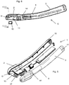
- a preferred embodiment of a device 1 for three-dimensional recording of objects 10, in particular teeth is shown, which has a receiving area 2 and a handle portion 3. Between receiving area 2 and handle area 3, a central area 5 is arranged in the illustrated embodiment. Since the middle region 5 has smaller outer dimensions than the receiving region 2, the receiving region 2 has a substantially conical transition region 6 towards the middle region 5. At the front end 4 of the receiving area 2 is rounded.
- the receiving area 2 has a central axis 7, the grip area 3 of the central axis 8 and the central area 5 a central axis 9.
- the angle ⁇ between the central axis 7 and the Central axis 8 is according to the invention between 10 ° and 40 °, said angle ⁇ in the illustrated embodiment (with a central region 5) divided into two angles ⁇ and ⁇ , wherein the angle ⁇ between the central axis 7 of the receiving part 2 and the central axis 9 of the central region 5 and the angle ⁇ between the central axis 9 of the central region 5 and the central axis 8 of the handle part 3 is located.
- the angle ⁇ is preferably between 3 ° and 15 ° and the angle ⁇ between 7 ° and 25 °.
- the length of the receiving area is preferably between 10 and 60 mm, since within these limits, both a good handling of the handpiece 1 and sufficient space for accommodating the projection and / or recording technique is available.
- an opening 12 ( Fig. 5 ), which is closed by a disc 13.
- light in particular a random pattern, can be directed onto the object 10 with a projector 14 and images of the object 10 can be taken with a camera system 15.
- the receiving area 2 is thus inclined relative to the handle 3 by an angle ⁇ between 10 ° and 40 ° counter to the direction of projection to the rear.
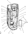
- Fig. 5 to 8 an embodiment of the invention is shown in which the projector 14 emits a light beam 23 with a light source.
- the light beam 23 passes through one or more in Fig. 9 illustrated transparent supports 36, 37, for example slides, on which a randomly arranged pattern is arranged.
- the pattern preferably consists of substantially randomly distributed, possibly irregularly shaped dots and / or lines, which are subsequently projected onto the object 10, for example a tooth.
- a deflection mirror 26 which is a part 23 a of the light beam 23, in the embodiment of Fig. 7 the lowest part, on a first mirror 27 deflects, which subsequently directs the light on the object 10.
- the deflection mirror 26 is preferably a plane mirror, but could also be a convex or concave curved mirror if required.
- the two mirrors 27 and 28 are preferably biaxially convexly curved mirrors with identical or different radii of curvature in the two axes, with which the respective portion of the radiation beam 23 can be scattered more strongly as required.
- the arrangement and curvature of the deflecting mirror 26 and the first mirror 27 is selected so that the part 23a of the light beam 23 in the image plane of the drawing has an opening angle ⁇ of about 30 °.
- the arrangement and curvature of the second mirror 28 is chosen by way of example so that the part 23b of the light beam 23 in the image plane of the drawing has an opening angle ⁇ of about 25 °.
- the opening angle of the parts 23a, 23b of the light beam 23 in the direction normal to the image plane of the drawing can, by suitable curvature of the mirrors 27, 28 be equal to or different from the respective opening angle ⁇ , ⁇ lying in the image plane.
- Exemplary selected arrangement of the mirrors 27, 28 are their optical axes 29, 30 inclined to each other so that the light beam parts 23a, 23b from different directions on the object 10 meet.
- a camera system 15 is arranged, which consists in the illustrated embodiment of two cameras 32 which record stereoscopic images for three-dimensional measurement of the object 10 , by doing they take pictures from different directions with overlapping shot areas.
- the two optical axes 29, 30 of the mirrors 27, 28 span a plane ⁇ , the two cameras 32, more precisely their lenses 33, lying symmetrically on both sides of this plane ⁇ .
- the camera system 15 with the mirrors 26, 27 and their optical axes 29, 30 in a plane w which allows a very precise image acquisition and thus measurement of the object.
- an illumination or projection of the random pattern on the object 10 takes place from two sides in this plane ⁇ , whereby - from the viewpoint of the camera system 15, shadows or imperfections on the object 10, which can occur, for example, in molars or incisors, can be avoided very reliably.
- a diaphragm 34 is disposed in the area above the deflection mirror 26, which blocks a third part 23c of the light beam 23 so that it does not cause unwanted reflections in the optics 33 of the cameras 32.
- the diaphragm 34 may also be omitted or arranged or shaped differently.
- All mirrors 26, 27, 28, the diaphragm 34 and optionally also the camera system 15 can be adjusted to appropriate Mounts 31 may be attached so that if necessary, a simple adjustment and / or calibration of the individual components is possible.
- all or even a portion of the components described above may be mounted and preset on a carrier system which may then be inserted into a recorder.
- the housing of the device 1 preferably consists of two housing halves 16, 17, which are designed mirror-symmetrically, whereby the device can be very easily assembled together.
- Fig. 5 to 8 described arrangement of the mirrors and cameras in handpieces with an angled receiving area 2 and possibly central area 5 is used, since by the mirror 26, 27, 28 a particularly good opportunity is offered to incorporate the entire projection and recording technique in an angled handpiece 1, which is very slim and is particularly easy to handle thanks to the kink, especially with oral scanners.
- an optimal degree of sharpness can already be achieved directly from the outer surface of the scanner glass 13 without the risk of shadows or imperfections, in order to be able to rest on an object, e.g. a tooth, this can already be measured, whereas known scanners often have to be kept at a certain distance to the teeth, which significantly hampers the recording process, in comparison to the inventive possibility also directly on the teeth can.
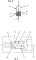
- Fig. 9 schematically an embodiment of the invention is shown, in which two transparent support 36, 37, for example two slides, on which randomly arranged patterns are arranged in the beam path of a light beam 23, which is emitted by a light source 22, for example an LED.
- the pattern may consist essentially of randomly distributed, possibly irregularly shaped, dots and / or lines.
- the light passes in the illustrated embodiment first through a lens 35, then through the two carriers 36, 37, and subsequently through a symbolically represented by a lens 38 further lens system which serves to align the projection beam 23 and focus adjustment.
- the projector 14 of Fig. 9 For example, at one in the Fig. 5 to 8 be used, in which the light beam 23 is directed via two mirrors 27 and 28 to an object 10. Since the light travels paths of different lengths, depending on whether it hits the object 10 either via the deflection mirror 26 and the mirror 27 or via the mirror 28, blurring of the one can occur when the pattern on a support is projected onto the object 10 or other or both projections.
- two carriers 36, 37 can be taken into account and blurring can be compensated individually. This can be done, for example, that the two carriers 36, 37 are offset in the direction of propagation of the light to each other.
- the carrier 36 which lies in the beam path of the light beam 23b of the mirror 28, farther back or further away from the lens 38 and a subsequent lens system than the carrier 37, which is in the beam path of the light beam 23a of the mirror 27, so overall, the path of the light from the respective carrier 36, 37 over the respective mirror 26, 27, 28 to the object 10 is again approximately the same length.
- Decisive are the different distances of the carriers 36, 37 to the lens system 38, since these distances determine the position and position of the focal plane in the measuring space.
- a single carrier could be used, either stepwise has stepped portions or indeed just but correspondingly strongly inclined to compensate for the path difference on average.
- a single carrier could be used, which is coated on different areas or sections respectively on the front and on the back with a pattern. The thickness of the carrier material then determines the distance difference.
- Fig. 9 is an inclination of the carrier 36, 37 to see the propagation direction of the light, that is, that the carrier 36, 37 are not exactly at right angles to the direction of propagation of the light.
- This embodiment of the invention is advantageous if the projector 14 or its optical center axis 39 as in the in the Fig. 1 to 8 illustrated embodiment is aligned at an angle ⁇ greater than 0 ° to the receiving area 2, in particular the optical center axis 39 is not aligned at right angles to the optical center axis 40 of the camera 32.
- the arrangement of the projector 14 in the angled transition region between the receiving area 2, in which the cameras are 32, and the central area 5 is particularly advantageous, since in this way the receiving area 2 can be kept relatively short, which significantly improves the handling of the handpiece 1 , Due to the inclination of the carrier 36, 37 caused by the inclination of the projector 14 blurring of projected onto the object 10 pattern can be compensated.
Landscapes
- Health & Medical Sciences (AREA)
- Physics & Mathematics (AREA)
- General Health & Medical Sciences (AREA)
- Public Health (AREA)
- Dentistry (AREA)
- Epidemiology (AREA)
- Life Sciences & Earth Sciences (AREA)
- Animal Behavior & Ethology (AREA)
- Optics & Photonics (AREA)
- Oral & Maxillofacial Surgery (AREA)
- Veterinary Medicine (AREA)
- Engineering & Computer Science (AREA)
- Computer Vision & Pattern Recognition (AREA)
- General Physics & Mathematics (AREA)
- Length Measuring Devices By Optical Means (AREA)
- Dental Tools And Instruments Or Auxiliary Dental Instruments (AREA)
Applications Claiming Priority (1)
| Application Number | Priority Date | Filing Date | Title |
|---|---|---|---|
| ATA387/2011A AT511223B1 (de) | 2011-03-18 | 2011-03-18 | Vorrichtung zum aufnehmen von bildern von dreidimensionalen objekten |
Publications (3)
| Publication Number | Publication Date |
|---|---|
| EP2499992A2 true EP2499992A2 (fr) | 2012-09-19 |
| EP2499992A3 EP2499992A3 (fr) | 2013-05-22 |
| EP2499992B1 EP2499992B1 (fr) | 2017-09-13 |
Family
ID=45977331
Family Applications (1)
| Application Number | Title | Priority Date | Filing Date |
|---|---|---|---|
| EP12450016.6A Not-in-force EP2499992B1 (fr) | 2011-03-18 | 2012-03-12 | Dispositif de capture d'images d'objets tridimensionnels |
Country Status (3)
| Country | Link |
|---|---|
| US (1) | US9101434B2 (fr) |
| EP (1) | EP2499992B1 (fr) |
| AT (1) | AT511223B1 (fr) |
Families Citing this family (4)
| Publication number | Priority date | Publication date | Assignee | Title |
|---|---|---|---|---|
| DE102012100953B4 (de) * | 2012-02-06 | 2020-01-09 | A.Tron3D Gmbh | Vorrichtung zum Erfassen der dreidimensionalen Geometrie von Objekten und Verfahren zum Betreiben derselben |
| EP3368858A4 (fr) | 2015-10-30 | 2019-06-26 | Carestream Dental Technology Topco Limited | Cible avec éléments pour étalonnage de scanner 3d |
| US10835352B2 (en) * | 2018-03-19 | 2020-11-17 | 3D Imaging and Simulation Corp. Americas | Intraoral scanner and computing system for capturing images and generating three-dimensional models |
| CN119451642A (zh) * | 2022-05-26 | 2025-02-14 | 阿莱恩技术有限公司 | 具有波导图案投影仪的口内扫描仪 |
Citations (1)
| Publication number | Priority date | Publication date | Assignee | Title |
|---|---|---|---|---|
| AT508563B1 (de) | 2009-10-07 | 2011-02-15 | Ait Austrian Inst Technology | Verfahren zur aufnahme dreidimensionaler abbilder |
Family Cites Families (12)
| Publication number | Priority date | Publication date | Assignee | Title |
|---|---|---|---|---|
| DE9013454U1 (de) * | 1990-08-29 | 1992-01-09 | Siemens AG, 8000 München | 3D-Kamera zur Erfassung von Oberflächenstrukturen, insbesondere für zahnmedizinische Zwecke |
| BR9709679A (pt) * | 1996-06-13 | 2000-01-11 | Leuven K U Res & Dev | Sistema e processo para alcançar uma descrição de forma tridimencional. |
| DE19818076A1 (de) * | 1997-04-22 | 1998-11-05 | Wolf & Beck Gmbh Dr | Verfahren zur berührungsfreien Vermessung einer Objektfläche sowie Vorrichtung zur Durchführung des Verfahrens |
| DE19747061B4 (de) * | 1997-10-24 | 2005-02-10 | Mähner, Bernward | Verfahren und Einrichtung zur flächenhaften, dreidimensionalen, optischen Vermessung von Objekten |
| US20030072011A1 (en) * | 2001-10-09 | 2003-04-17 | Shirley Lyle G. | Method and apparatus for combining views in three-dimensional surface profiling |
| DE102007060263A1 (de) | 2007-08-16 | 2009-02-26 | Steinbichler Optotechnik Gmbh | Vorrichtung zur Ermittlung der 3D-Koordinaten eines Objekts, insbesondere eines Zahns |
| DE102007054906B4 (de) * | 2007-11-15 | 2011-07-28 | Sirona Dental Systems GmbH, 64625 | Verfahren zur optischen Vermessung der dreidimensionalen Geometrie von Objekten |
| DE102007054907A1 (de) * | 2007-11-15 | 2009-05-28 | Sirona Dental Systems Gmbh | Verfahren zur optischen Vermessung von Objekten unter Verwendung eines Triangulationsverfahrens |
| JP5317169B2 (ja) * | 2008-06-13 | 2013-10-16 | 洋 川崎 | 画像処理装置、画像処理方法およびプログラム |
| WO2010021972A1 (fr) * | 2008-08-18 | 2010-02-25 | Brown University | Éclairement structuré périphérique pour récupérer une forme et un aspect d'objet en 3d |
| EP2166304A1 (fr) * | 2008-09-23 | 2010-03-24 | Sick Ag | Unité d'éclairage et procédé de production d'un modèle auto-dissemblable |
| DE102010030833B4 (de) * | 2009-07-03 | 2014-07-03 | Koh Young Technology Inc. | Vorrichtung zur Messung einer dreidimensionalen Form |
-
2011
- 2011-03-18 AT ATA387/2011A patent/AT511223B1/de not_active IP Right Cessation
-
2012
- 2012-03-12 EP EP12450016.6A patent/EP2499992B1/fr not_active Not-in-force
- 2012-03-19 US US13/423,351 patent/US9101434B2/en not_active Expired - Fee Related
Patent Citations (1)
| Publication number | Priority date | Publication date | Assignee | Title |
|---|---|---|---|---|
| AT508563B1 (de) | 2009-10-07 | 2011-02-15 | Ait Austrian Inst Technology | Verfahren zur aufnahme dreidimensionaler abbilder |
Also Published As
| Publication number | Publication date |
|---|---|
| EP2499992A3 (fr) | 2013-05-22 |
| US9101434B2 (en) | 2015-08-11 |
| AT511223B1 (de) | 2013-01-15 |
| US20120237889A1 (en) | 2012-09-20 |
| EP2499992B1 (fr) | 2017-09-13 |
| AT511223A1 (de) | 2012-10-15 |
Similar Documents
| Publication | Publication Date | Title |
|---|---|---|
| AT510554B1 (de) | Vorrichtung zum aufnehmen von bildern von dreidimensionalen objekten | |
| DE68918751T2 (de) | Bildaufnahme- und Verarbeitungseinrichtung. | |
| EP3154469B1 (fr) | Dispositif de mesure et procédé pour effectuer des mesures en trois dimensions d'une cavité buccale | |
| EP0519915B1 (fr) | Procede et dispositif de mesure d'un espace, notamment de l'interieur de la bouche | |
| EP0923704B1 (fr) | Procede et dispositif d'obtention d'images par moyens optiques | |
| EP1618836B1 (fr) | Laryngoscope avec tomographie à cohérence optique | |
| DE3784340T2 (de) | Elektronische video dental kamera. | |
| DE10141559B4 (de) | Videoendoskopsystem und Beleuchtungsoptik | |
| DE10027166A1 (de) | Stereoskopmikroskop | |
| EP2648597A1 (fr) | Endoscope et procédé de prise de vue d'au moins une image stéréoscopique à l'aide d'un endoscope | |
| DE10027167A1 (de) | Mikroskop mit einem Beleuchtungssystem | |
| EP1262751A2 (fr) | Dispositif et procédé d'analyse de lumière | |
| EP3293558B1 (fr) | Dispositif de détection d'une image stéréo | |
| DE4136002A1 (de) | Moire- konturenabbildungsvorrichtung | |
| EP2499992B1 (fr) | Dispositif de capture d'images d'objets tridimensionnels | |
| DE10027204A1 (de) | Stereoskopmikroskop | |
| EP1417925A1 (fr) | Appareil pour visualiser un oeil | |
| DE10156434A1 (de) | Videoendoskop und Videoendoskopsystem | |
| CH714591A1 (de) | Augenuntersuchungsgerät und Verfahren zum Ermitteln von Bilddaten. | |
| WO2011076416A1 (fr) | Procédé et système de production d'images radiographiques sans distorsion pour le diagnostic en odontologie ou en orthodontie | |
| DE10027196A1 (de) | Video-Stereoskopmikroskop | |
| DE102009008747B4 (de) | Optisches Abbildungssystem | |
| DE10130119A1 (de) | Videomikroskop | |
| EP2499991B1 (fr) | Dispositif de capture d'images d'objets tridimensionnels | |
| DE102013200135A1 (de) | Telezentrisches Abbildungssystem |
Legal Events
| Date | Code | Title | Description |
|---|---|---|---|
| PUAI | Public reference made under article 153(3) epc to a published international application that has entered the european phase |
Free format text: ORIGINAL CODE: 0009012 |
|
| AK | Designated contracting states |
Kind code of ref document: A2 Designated state(s): AL AT BE BG CH CY CZ DE DK EE ES FI FR GB GR HR HU IE IS IT LI LT LU LV MC MK MT NL NO PL PT RO RS SE SI SK SM TR |
|
| AX | Request for extension of the european patent |
Extension state: BA ME |
|
| PUAL | Search report despatched |
Free format text: ORIGINAL CODE: 0009013 |
|
| AK | Designated contracting states |
Kind code of ref document: A3 Designated state(s): AL AT BE BG CH CY CZ DE DK EE ES FI FR GB GR HR HU IE IS IT LI LT LU LV MC MK MT NL NO PL PT RO RS SE SI SK SM TR |
|
| AX | Request for extension of the european patent |
Extension state: BA ME |
|
| RIC1 | Information provided on ipc code assigned before grant |
Ipc: A61C 9/00 20060101AFI20130412BHEP Ipc: G01B 11/25 20060101ALI20130412BHEP |
|
| RAP1 | Party data changed (applicant data changed or rights of an application transferred) |
Owner name: A.TRON3D GMBH |
|
| 17P | Request for examination filed |
Effective date: 20131111 |
|
| RBV | Designated contracting states (corrected) |
Designated state(s): AL AT BE BG CH CY CZ DE DK EE ES FI FR GB GR HR HU IE IS IT LI LT LU LV MC MK MT NL NO PL PT RO RS SE SI SK SM TR |
|
| 17Q | First examination report despatched |
Effective date: 20140212 |
|
| GRAP | Despatch of communication of intention to grant a patent |
Free format text: ORIGINAL CODE: EPIDOSNIGR1 |
|
| INTG | Intention to grant announced |
Effective date: 20170412 |
|
| GRAS | Grant fee paid |
Free format text: ORIGINAL CODE: EPIDOSNIGR3 |
|
| GRAA | (expected) grant |
Free format text: ORIGINAL CODE: 0009210 |
|
| AK | Designated contracting states |
Kind code of ref document: B1 Designated state(s): AL AT BE BG CH CY CZ DE DK EE ES FI FR GB GR HR HU IE IS IT LI LT LU LV MC MK MT NL NO PL PT RO RS SE SI SK SM TR |
|
| REG | Reference to a national code |
Ref country code: GB Ref legal event code: FG4D Free format text: NOT ENGLISH |
|
| REG | Reference to a national code |
Ref country code: CH Ref legal event code: EP |
|
| REG | Reference to a national code |
Ref country code: IE Ref legal event code: FG4D Free format text: LANGUAGE OF EP DOCUMENT: GERMAN |
|
| REG | Reference to a national code |
Ref country code: AT Ref legal event code: REF Ref document number: 927416 Country of ref document: AT Kind code of ref document: T Effective date: 20171015 |
|
| REG | Reference to a national code |
Ref country code: DE Ref legal event code: R096 Ref document number: 502012011260 Country of ref document: DE |
|
| REG | Reference to a national code |
Ref country code: NL Ref legal event code: MP Effective date: 20170913 |
|
| REG | Reference to a national code |
Ref country code: LT Ref legal event code: MG4D |
|
| PG25 | Lapsed in a contracting state [announced via postgrant information from national office to epo] |
Ref country code: LT Free format text: LAPSE BECAUSE OF FAILURE TO SUBMIT A TRANSLATION OF THE DESCRIPTION OR TO PAY THE FEE WITHIN THE PRESCRIBED TIME-LIMIT Effective date: 20170913 Ref country code: SE Free format text: LAPSE BECAUSE OF FAILURE TO SUBMIT A TRANSLATION OF THE DESCRIPTION OR TO PAY THE FEE WITHIN THE PRESCRIBED TIME-LIMIT Effective date: 20170913 Ref country code: FI Free format text: LAPSE BECAUSE OF FAILURE TO SUBMIT A TRANSLATION OF THE DESCRIPTION OR TO PAY THE FEE WITHIN THE PRESCRIBED TIME-LIMIT Effective date: 20170913 Ref country code: NO Free format text: LAPSE BECAUSE OF FAILURE TO SUBMIT A TRANSLATION OF THE DESCRIPTION OR TO PAY THE FEE WITHIN THE PRESCRIBED TIME-LIMIT Effective date: 20171213 Ref country code: HR Free format text: LAPSE BECAUSE OF FAILURE TO SUBMIT A TRANSLATION OF THE DESCRIPTION OR TO PAY THE FEE WITHIN THE PRESCRIBED TIME-LIMIT Effective date: 20170913 |
|
| PG25 | Lapsed in a contracting state [announced via postgrant information from national office to epo] |
Ref country code: RS Free format text: LAPSE BECAUSE OF FAILURE TO SUBMIT A TRANSLATION OF THE DESCRIPTION OR TO PAY THE FEE WITHIN THE PRESCRIBED TIME-LIMIT Effective date: 20170913 Ref country code: ES Free format text: LAPSE BECAUSE OF FAILURE TO SUBMIT A TRANSLATION OF THE DESCRIPTION OR TO PAY THE FEE WITHIN THE PRESCRIBED TIME-LIMIT Effective date: 20170913 Ref country code: LV Free format text: LAPSE BECAUSE OF FAILURE TO SUBMIT A TRANSLATION OF THE DESCRIPTION OR TO PAY THE FEE WITHIN THE PRESCRIBED TIME-LIMIT Effective date: 20170913 Ref country code: BG Free format text: LAPSE BECAUSE OF FAILURE TO SUBMIT A TRANSLATION OF THE DESCRIPTION OR TO PAY THE FEE WITHIN THE PRESCRIBED TIME-LIMIT Effective date: 20171213 Ref country code: GR Free format text: LAPSE BECAUSE OF FAILURE TO SUBMIT A TRANSLATION OF THE DESCRIPTION OR TO PAY THE FEE WITHIN THE PRESCRIBED TIME-LIMIT Effective date: 20171214 |
|
| PG25 | Lapsed in a contracting state [announced via postgrant information from national office to epo] |
Ref country code: NL Free format text: LAPSE BECAUSE OF FAILURE TO SUBMIT A TRANSLATION OF THE DESCRIPTION OR TO PAY THE FEE WITHIN THE PRESCRIBED TIME-LIMIT Effective date: 20170913 |
|
| PG25 | Lapsed in a contracting state [announced via postgrant information from national office to epo] |
Ref country code: CZ Free format text: LAPSE BECAUSE OF FAILURE TO SUBMIT A TRANSLATION OF THE DESCRIPTION OR TO PAY THE FEE WITHIN THE PRESCRIBED TIME-LIMIT Effective date: 20170913 Ref country code: RO Free format text: LAPSE BECAUSE OF FAILURE TO SUBMIT A TRANSLATION OF THE DESCRIPTION OR TO PAY THE FEE WITHIN THE PRESCRIBED TIME-LIMIT Effective date: 20170913 Ref country code: PL Free format text: LAPSE BECAUSE OF FAILURE TO SUBMIT A TRANSLATION OF THE DESCRIPTION OR TO PAY THE FEE WITHIN THE PRESCRIBED TIME-LIMIT Effective date: 20170913 |
|
| PG25 | Lapsed in a contracting state [announced via postgrant information from national office to epo] |
Ref country code: SM Free format text: LAPSE BECAUSE OF FAILURE TO SUBMIT A TRANSLATION OF THE DESCRIPTION OR TO PAY THE FEE WITHIN THE PRESCRIBED TIME-LIMIT Effective date: 20170913 Ref country code: IS Free format text: LAPSE BECAUSE OF FAILURE TO SUBMIT A TRANSLATION OF THE DESCRIPTION OR TO PAY THE FEE WITHIN THE PRESCRIBED TIME-LIMIT Effective date: 20180113 Ref country code: SK Free format text: LAPSE BECAUSE OF FAILURE TO SUBMIT A TRANSLATION OF THE DESCRIPTION OR TO PAY THE FEE WITHIN THE PRESCRIBED TIME-LIMIT Effective date: 20170913 Ref country code: IT Free format text: LAPSE BECAUSE OF FAILURE TO SUBMIT A TRANSLATION OF THE DESCRIPTION OR TO PAY THE FEE WITHIN THE PRESCRIBED TIME-LIMIT Effective date: 20170913 Ref country code: EE Free format text: LAPSE BECAUSE OF FAILURE TO SUBMIT A TRANSLATION OF THE DESCRIPTION OR TO PAY THE FEE WITHIN THE PRESCRIBED TIME-LIMIT Effective date: 20170913 |
|
| REG | Reference to a national code |
Ref country code: DE Ref legal event code: R097 Ref document number: 502012011260 Country of ref document: DE |
|
| PLBE | No opposition filed within time limit |
Free format text: ORIGINAL CODE: 0009261 |
|
| STAA | Information on the status of an ep patent application or granted ep patent |
Free format text: STATUS: NO OPPOSITION FILED WITHIN TIME LIMIT |
|
| PG25 | Lapsed in a contracting state [announced via postgrant information from national office to epo] |
Ref country code: DK Free format text: LAPSE BECAUSE OF FAILURE TO SUBMIT A TRANSLATION OF THE DESCRIPTION OR TO PAY THE FEE WITHIN THE PRESCRIBED TIME-LIMIT Effective date: 20170913 |
|
| 26N | No opposition filed |
Effective date: 20180614 |
|
| PG25 | Lapsed in a contracting state [announced via postgrant information from national office to epo] |
Ref country code: MT Free format text: LAPSE BECAUSE OF FAILURE TO SUBMIT A TRANSLATION OF THE DESCRIPTION OR TO PAY THE FEE WITHIN THE PRESCRIBED TIME-LIMIT Effective date: 20170913 |
|
| REG | Reference to a national code |
Ref country code: CH Ref legal event code: PL |
|
| GBPC | Gb: european patent ceased through non-payment of renewal fee |
Effective date: 20180312 |
|
| PG25 | Lapsed in a contracting state [announced via postgrant information from national office to epo] |
Ref country code: MC Free format text: LAPSE BECAUSE OF FAILURE TO SUBMIT A TRANSLATION OF THE DESCRIPTION OR TO PAY THE FEE WITHIN THE PRESCRIBED TIME-LIMIT Effective date: 20170913 Ref country code: SI Free format text: LAPSE BECAUSE OF FAILURE TO SUBMIT A TRANSLATION OF THE DESCRIPTION OR TO PAY THE FEE WITHIN THE PRESCRIBED TIME-LIMIT Effective date: 20170913 |
|
| REG | Reference to a national code |
Ref country code: BE Ref legal event code: MM Effective date: 20180331 |
|
| REG | Reference to a national code |
Ref country code: IE Ref legal event code: MM4A |
|
| PG25 | Lapsed in a contracting state [announced via postgrant information from national office to epo] |
Ref country code: LU Free format text: LAPSE BECAUSE OF NON-PAYMENT OF DUE FEES Effective date: 20180312 |
|
| PG25 | Lapsed in a contracting state [announced via postgrant information from national office to epo] |
Ref country code: IE Free format text: LAPSE BECAUSE OF NON-PAYMENT OF DUE FEES Effective date: 20180312 |
|
| PG25 | Lapsed in a contracting state [announced via postgrant information from national office to epo] |
Ref country code: CH Free format text: LAPSE BECAUSE OF NON-PAYMENT OF DUE FEES Effective date: 20180331 Ref country code: GB Free format text: LAPSE BECAUSE OF NON-PAYMENT OF DUE FEES Effective date: 20180312 Ref country code: LI Free format text: LAPSE BECAUSE OF NON-PAYMENT OF DUE FEES Effective date: 20180331 Ref country code: BE Free format text: LAPSE BECAUSE OF NON-PAYMENT OF DUE FEES Effective date: 20180331 |
|
| PG25 | Lapsed in a contracting state [announced via postgrant information from national office to epo] |
Ref country code: FR Free format text: LAPSE BECAUSE OF NON-PAYMENT OF DUE FEES Effective date: 20180331 |
|
| REG | Reference to a national code |
Ref country code: AT Ref legal event code: MM01 Ref document number: 927416 Country of ref document: AT Kind code of ref document: T Effective date: 20180312 |
|
| PG25 | Lapsed in a contracting state [announced via postgrant information from national office to epo] |
Ref country code: AT Free format text: LAPSE BECAUSE OF NON-PAYMENT OF DUE FEES Effective date: 20180312 |
|
| PG25 | Lapsed in a contracting state [announced via postgrant information from national office to epo] |
Ref country code: TR Free format text: LAPSE BECAUSE OF FAILURE TO SUBMIT A TRANSLATION OF THE DESCRIPTION OR TO PAY THE FEE WITHIN THE PRESCRIBED TIME-LIMIT Effective date: 20170913 |
|
| PG25 | Lapsed in a contracting state [announced via postgrant information from national office to epo] |
Ref country code: PT Free format text: LAPSE BECAUSE OF FAILURE TO SUBMIT A TRANSLATION OF THE DESCRIPTION OR TO PAY THE FEE WITHIN THE PRESCRIBED TIME-LIMIT Effective date: 20170913 Ref country code: HU Free format text: LAPSE BECAUSE OF FAILURE TO SUBMIT A TRANSLATION OF THE DESCRIPTION OR TO PAY THE FEE WITHIN THE PRESCRIBED TIME-LIMIT; INVALID AB INITIO Effective date: 20120312 |
|
| PG25 | Lapsed in a contracting state [announced via postgrant information from national office to epo] |
Ref country code: CY Free format text: LAPSE BECAUSE OF FAILURE TO SUBMIT A TRANSLATION OF THE DESCRIPTION OR TO PAY THE FEE WITHIN THE PRESCRIBED TIME-LIMIT Effective date: 20170913 Ref country code: MK Free format text: LAPSE BECAUSE OF NON-PAYMENT OF DUE FEES Effective date: 20170913 |
|
| PG25 | Lapsed in a contracting state [announced via postgrant information from national office to epo] |
Ref country code: AL Free format text: LAPSE BECAUSE OF FAILURE TO SUBMIT A TRANSLATION OF THE DESCRIPTION OR TO PAY THE FEE WITHIN THE PRESCRIBED TIME-LIMIT Effective date: 20170913 |
|
| PGFP | Annual fee paid to national office [announced via postgrant information from national office to epo] |
Ref country code: DE Payment date: 20220525 Year of fee payment: 11 |
|
| REG | Reference to a national code |
Ref country code: DE Ref legal event code: R119 Ref document number: 502012011260 Country of ref document: DE |
|
| PG25 | Lapsed in a contracting state [announced via postgrant information from national office to epo] |
Ref country code: DE Free format text: LAPSE BECAUSE OF NON-PAYMENT OF DUE FEES Effective date: 20231003 |