EP2500122A1 - Ebavurage de tuyau, notamment pour tuyaux de systèmes press-fit, ainsi que dispositif d'ébavurage doté d'un tel ébavurage de tuyaux - Google Patents
Ebavurage de tuyau, notamment pour tuyaux de systèmes press-fit, ainsi que dispositif d'ébavurage doté d'un tel ébavurage de tuyaux Download PDFInfo
- Publication number
- EP2500122A1 EP2500122A1 EP12001116A EP12001116A EP2500122A1 EP 2500122 A1 EP2500122 A1 EP 2500122A1 EP 12001116 A EP12001116 A EP 12001116A EP 12001116 A EP12001116 A EP 12001116A EP 2500122 A1 EP2500122 A1 EP 2500122A1
- Authority
- EP
- European Patent Office
- Prior art keywords
- deburring
- pipe
- housing
- deburrer
- friction
- Prior art date
- Legal status (The legal status is an assumption and is not a legal conclusion. Google has not performed a legal analysis and makes no representation as to the accuracy of the status listed.)
- Granted
Links
Images
Classifications
-
- B—PERFORMING OPERATIONS; TRANSPORTING
- B23—MACHINE TOOLS; METAL-WORKING NOT OTHERWISE PROVIDED FOR
- B23B—TURNING; BORING
- B23B5/00—Turning-machines or devices specially adapted for particular work; Accessories specially adapted therefor
- B23B5/16—Turning-machines or devices specially adapted for particular work; Accessories specially adapted therefor for bevelling, chamfering, or deburring the ends of bars or tubes
- B23B5/165—Workpieces clamped on a bench, e.g. a vice
-
- B—PERFORMING OPERATIONS; TRANSPORTING
- B23—MACHINE TOOLS; METAL-WORKING NOT OTHERWISE PROVIDED FOR
- B23B—TURNING; BORING
- B23B5/00—Turning-machines or devices specially adapted for particular work; Accessories specially adapted therefor
- B23B5/16—Turning-machines or devices specially adapted for particular work; Accessories specially adapted therefor for bevelling, chamfering, or deburring the ends of bars or tubes
- B23B5/167—Tools for chamfering the ends of bars or tubes
- B23B5/168—Tools for chamfering the ends of bars or tubes with guiding devices
-
- B—PERFORMING OPERATIONS; TRANSPORTING
- B23—MACHINE TOOLS; METAL-WORKING NOT OTHERWISE PROVIDED FOR
- B23B—TURNING; BORING
- B23B51/00—Tools for drilling machines
- B23B51/10—Bits for countersinking
- B23B51/103—Deburring or chamfering tools for the ends of tubes or rods
-
- B—PERFORMING OPERATIONS; TRANSPORTING
- B23—MACHINE TOOLS; METAL-WORKING NOT OTHERWISE PROVIDED FOR
- B23D—PLANING; SLOTTING; SHEARING; BROACHING; SAWING; FILING; SCRAPING; LIKE OPERATIONS FOR WORKING METAL BY REMOVING MATERIAL, NOT OTHERWISE PROVIDED FOR
- B23D21/00—Machines or devices for shearing or cutting tubes
- B23D21/006—Machines or devices for shearing or cutting tubes and sealing, crushing or chamfering the tubes
Definitions
- the invention relates to a pipe deburrer, in particular for pipes of press fitting systems, according to the preamble of claim 1 and a deburring device with such a pipe deburrer according to the preamble of claim 6.
- pipes of stainless steel, copper and plastic for the installation of press fitting systems are advantageously separated with tools with a cutting wheel. This creates only a minimal outer ridge.
- a more or less strong inner burr is produced by the non-cutting separation process with the cutting wheel.
- multi-tooth pipe deburrers are used, which are pressed by hand, possibly driven by a drill, against the severed pipe.
- the pipe section to be deburred is usually held by hand. For pipes with a larger diameter up to about 108 mm this is However, technology is not possible because neither the pipe sections nor a correspondingly heavy, large and thus unwieldy pipe deburrer can be held with one hand.
- the invention is therefore the object of the generic deburring device and the generic deburring device in such a way that the pipes, especially of press fitting systems, can be easily and inexpensively deburred even with large pipe diameter.
- the pipe deburrer according to the invention has a housing which is provided on its cylindrical outer side with at least one peripheral friction element. With its help, it is possible to rotatably drive the Rohrentgrater about its axis, so that the pipe to be deburred, even if it should have a large diameter, can be held by hand. On circumferentially provided on the housing friction element can engage a friction wheel, which sets the Rohrentgrater in rotation.
- the pipe to be deburred does not have to be turned around its axis so that the deburring process can be carried out without problems.
- the friction element is attached to the housing of the Rohrentgraters Reibkranz. It can be provided at least on its upper side with a corresponding friction lining or be made entirely from a corresponding friction material.
- the friction element is provided with a circumferential recess.
- a deburring blade is advantageously used, which projects with at least one blade part either outwardly over the housing and / or inwardly over the inner wall of the housing.
- a mecanical gulft With the outwardly projecting blade part a mecanical gulfung can be made while with the on the inside of the housing projecting blade part, the tube can be deburred on the outside.
- the deburring blade is a simple and inexpensive to manufacture component that can be easily installed in the housing.
- the deburring part is advantageously fastened in the housing by at least one securing element.
- the securing element is provided so that it presses the deburring in its mounting position within the housing.
- the roller support is provided, which has at least two spaced-apart, freely rotatable rollers. They form the support for the pipe deburrer, which is placed on the parallel freely rotating rollers.
- the deburring device is provided with a rotatably driven friction wheel, which is brought to the rotary drive of the Rohrentgraters in frictional engagement with the friction element of the Rohrentgraters. The friction wheel abuts with its lateral surface on the lateral surface of the friction element. Since the friction wheel is rotatably driven, by the frictional engagement of the Rohrentgrater on the rollers driven in rotation about its axis.
- the friction wheel can advantageously be adjusted transversely to its axis of rotation. In this way, the contact pressure of the friction wheel can be adjusted on the friction element.
- the friction wheel is adjusted along a stand.
- a threaded spindle is accommodated in the stator. It is provided parallel to a straight guide in the stator for the adjustment of the friction wheel.
- a spindle nut On the threaded spindle sits a spindle nut which is connected to a motor / gear housing. Depending on the direction of rotation of the threaded spindle, the motor / gearbox housing is adjusted upwards or downwards via the spindle nut.
- the threaded spindle allows a stepless adjustment of the motor / gear housing.
- a motor / gearbox is provided for the friction wheel, which is thus adjusted by adjusting the engine / transmission housing in the respective position.
- the friction wheel is a cutting wheel for severing the tube.
- a deburring on the pipe can be performed with the deburring. It is placed on the freely rotating rollers.
- the cutting wheel is moved against the pipe to be separated. Since the cutting wheel is rotatably driven, and the tube lying on the freely rotatable rollers in rotation offset around its axis as soon as the cutting wheel engages the pipe. In this way, the tube is rotated about its axis and severed by means of the rotatably driven cutting wheel.
- This cutting wheel is used as a friction wheel during the deburring process. So that the cutting wheel does not damage or even destroy the friction element of the pipe deburrer with its peripheral cutting edge, the peripheral cutting edge engages in the circumferential depression of the friction element of the pipe deburrer.
- the recess is formed so that the peripheral edge does not come into contact with the bottom of the recess.
- the cylindrical lateral surface can be used in the area adjacent to the peripheral cutting edge of the cutting wheel for the frictional engagement with the friction element in order to rotate the tube deburrer resting on the rollers for the deburring process about its axis.
- the pipe deburrer and the friction wheel advantageously have mutually parallel axes of rotation. As a result, a simple rotation of the Rohrentgraters is ensured by the frictional engagement with the friction wheel.
- the deburring device described below is used for the internal de-sealing of pipes of pressfitting systems.
- Such pipes in press fitting systems are usually made of stainless steel, copper or plastic.
- tubes are deburred inside, which have larger diameters, for example in the range from 28 to 108 mm.
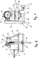
- the deburring device has a pipe deburrer with a deburrer housing 1 ( Fig. 1 and 5 to 8 ), which advantageously consists of metallic material.
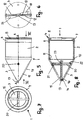
- the deburrer housing 1 has a cylindrical part 2 and a cone part 3, which adjoins the one end of the cylindrical part 2.
- the two parts 2, 3 are separate parts which are firmly connected to each other, for example by gluing, soldering or welding.
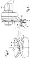
- a friction ring 4 is connected, which is annular and projects radially inwardly over the inner wall of the cylinder part 2 ( Fig. 4 and 8th ).
- the friction ring 4 has an axial annular projection 5, with which it engages in an open towards the front side annular recess 6 in the outer side of the cylinder part 2.
- the friction ring 4 has in its outer side. 7 a circumferential groove-shaped recess 8, in which a cutting wheel 9 (FIG. Fig. 4 ) intervenes.
- the cutting wheel 9 is rotatably driven in a manner to be described about its axis and pressed radially against the friction ring 4. Due to the friction between the cutting wheel 9 and the friction ring 4, the deburring housing 1 is rotatably driven about its axis.
- the cone part 3 of the Entgratergeophuses 1 also has an annular projection 10 which engages in a provided on the outside of the cylindrical part 2 of the Entgratergeophuses 1 circumferential recess 11. It is like the recess 6 open to the front side of the cylindrical part 2.
- the projection 10 of the cone part 3 is firmly connected to the cylindrical part 2, for example by gluing, soldering, welding or the like.
- the cone part 3 tapers steadily from the cylindrical part 2.
- the cone part 3 is provided with two diametrically opposed slots 12 ( Fig. 6 ), which extend from a central center 13 at the free end of the cone part 3 to close to the transition to the cylindrical part 2.
- the middle piece 13 closes off the cone part 3 and is provided on the inside with a receptacle 14 (FIG. Fig. 8 ) for a deburring blade 15. It has approximately triangular outline with a truncated triangle tip 16, which projects into the receptacle 14 of the central piece 13.
- the deburring blade 15 is designed such that it protrudes with a triangle side 17 through one of the two slots 12 (FIG. Fig. 5 ).
- This protruding part 17 of the deburring blade 15 removes the inner ridge on the tube.
- the projecting blade portion 17 extends over the entire length of the corresponding slot 12.
- the outer side of the cone part 3 is provided in the area adjacent to the slot 12 with a flattening 18 ( Fig. 6 ), so that the pipe deburring can be performed reliably.
- the deburring blade 15 can also be designed such that through the other slot 12 the other triangular side forming a blade part protrudes. Then the Entgratergepuruse 1 with two diametrically opposed Blade parts 17 provided, the cutting edges 19 remove the burr on the inside of the tube.
- the deburring blade 15 is secured in the cone part 13 by at least one securing element 20, preferably a tensioning pin.
- the securing element 20 is secured with its two ends in receptacles 21, 22 which are provided on the inside of the cone part 3 and are open to the outside. So that the securing element 20 is reliably held in the cone part 3, two thickenings are respectively provided on the inside of the cone part 3, which are respectively penetrated by an opening which is open to the outside of the cone part 3 and can be used by the securing element 20 from the outside ,
- the deburring blade 15 is provided with a passage opening 23 for the securing element 20.
- the securing element 20 is preferably a tensioning pin, it can be kept perfectly in the two receptacles 21, 22, so that the deburring blade 15 is held properly.
- the two ends of the securing element 20 are recessed, so that they do not protrude beyond the outside of the cone part 3 and thus can not affect the deburring process.
- the deburring blade 15 is pressed by the securing element 20 with its truncated triangle tip into the receptacle 14 of the middle piece 13.
- the deburring blade 15 is advantageously designed so that it is supported on the inside of the cone part 3. As a result, unwanted movements of the deburring blade 15 are avoided relative to the cone part 3, so that a clean deburring process is ensured.
- the cutting wheel 9 is part of a drive 24.
- the deburring device has a bed 25 (FIG. Fig. 1 and 2 ), on whose upper side a plurality of support rollers 26 to 29 are freely rotatably mounted. They advantageously have the same diameter and are advantageously provided with a friction lining.
- the rollers 26 to 29 are arranged so that they project slightly above V-shaped walls 30, 31 of a V-shaped recess 32.
- Wie out Fig. 1 shows the Entgratergephase 1 with its cylindrical part 2 on the two outer rollers 26, 29.
- the parallel rollers 26 to 29 are arranged by way of example so that the two outer rollers 26, 29 are at the same height, while the inner rollers 27, 28 are lower, but are also arranged at the same level.
- a vertical stand 33 On one side of the bed 25, a vertical stand 33 is provided, in which a vertical threaded spindle 34 rotatable about its axis (FIG. Fig. 2 ) is rotatably mounted. On it sits a (not shown) spindle nut, which can be moved by turning the threaded spindle 34 upwards and downwards.
- the threaded nut is connected to a motor / gear housing 35, in which a gear and a drive, preferably an electric motor, housed to rotatably drive the cutting wheel 9 about its axis.
- a lever 36 is provided on the side opposite the stand 33 of the bed 25, which is non-rotatably mounted on a shaft 37. It passes through the bed 25 near its support side perpendicular to the rollers 26 to 29. About a bevel gear, the shaft 37 is drivingly connected to the threaded spindle 34. By turning the lever 36 and thus the shaft 37 thus the threaded spindle 34 can be rotated to adjust the cutting wheel 9 with the motor / gear housing 35 up or down.
- the rotating cutting wheel 9 With the cutting wheel 9, it is possible to cut through a freely resting on the rollers 26 to 29 pipe by the rotating cutting wheel 9 is adjusted by means of the lever 36 against the pipe to be cut through.
- the driven cutting wheel 9 comes into contact with the tube, which is driven by the cutting wheel 9 about its axis rotating.
- the rollers on which the workpiece rests in each case are also rotated about their parallel axes by the rotating tube. In this way the pipe is completely severed.
- the motor / gear housing 35 with the cutting wheel 9 is moved upward until the cutting wheel 9 is above the cut-through tube.
- the tube is provided on the inside with a distinct ridge on the cut end, which is now removed.
- the pipe deburrer 1 is placed on the corresponding support rollers.
- the cutting wheel 9 is moved by means of the lever 36 back down, wherein the cutting wheel 9 engages in the groove-shaped recess 8 of the Entgratergephases 1 ( Fig. 4 ).
- the recess 8 is so deep and so wide that the peripheral cutting edge 38 of the cutting wheel 9 is not damaged, but has a distance from both the side walls and the bottom of the recess 8.
- the cutting wheel 9 is provided with a cylindrical jacket surface 39 which, when the motor / gear housing 35 is adjusted in the region of the groove-shaped recess 8, comes into contact with the outside 7 of the friction collar 4.
- the Entgratergezzause 1 is rotatably driven in this manner by frictional engagement about its axis.
- the support rollers 26, 29, on which the Entgratergeophuse 1 rests with its cylindrical part 2 are freely rotatable and also ensure proper positional securing the Entgratergephaseuses 1 in the radial direction.
- the severed piece of pipe is short, it can still be carried by hand even with a large diameter and pressed against the rotating pipe deburrer.
- the rotating deburring blade 15 removes with the cutting edge 19 the inside ridge of the pipe section. If the pipe has a greater length and can no longer be carried by hand, it is deposited, for example, on a height-adjustable bearing block and pressed by hand against the rotating pipe deburrer.
- the cone part 3 with the blade part 17 protrudes sufficiently far beyond the bed 25, so that the internal deburring process can be carried out without difficulty.
- the pipe deburrer is a réellerohrentgrater.
- the cylindrical part 2 of the Entgratergeophuses 1 is extended and formed instead of the cone part 3 on the inside of this elongated cylindrical housing part 2, an inner cone. It tapers in the direction of the cylindrical part 2 and is provided on the inside with at least one réelleentgratteil whose Entgratschneide lies on the mantle of an imaginary cone, which tapers in the direction of the cylindrical part 2.
- the drive of such beideentgraters done in the same manner as in the described réelleentgrater.
- the tube is inserted into the extended cylindrical part 2, with the deburring cutting edge located on the cone sheath removing the outer edge of the tube.
- the drive 24 is easy to transport and can therefore be easily used by the installer directly on the construction site.
- the drive 24 is compact and allows not only the cutting of pipes, but also the deburring.
- the deburring device described in particular, pipes with a large diameter can be easily deburred without the need for heavy, structurally large and hence unwieldy pipe deburrers.
- the deburring device is used for pipes of press fitting systems, but of course can also be used for other pipes.
- a conventional friction wheel can be used, which abuts with its cylindrical surface on the outside 7 of the friction ring 4 under pressure.
- the rotatably driven friction wheel offset due to the frictional engagement of the Rohrentgrater in rotation about its longitudinal axis.
- the friction ring 4 in this case need not have a groove-shaped recess 8, since the friction wheel is not provided with a peripheral cutting edge such as a cutting wheel. But even if the friction ring 4 is provided with the groove-shaped recess 8, the Rohrentgrater can also be reliably rotated by means of such a friction wheel.
- the friction wheel consists at least on its cylindrical surface of a corresponding friction material, which ensures the high frictional engagement with the friction ring 4.
- the contact pressure of the friction wheel on the friction ring 4 can in turn be optimally adjusted by means of the lever 36, so that the pipe deburrer is reliably rotatably driven. Due to the height adjustability of the motor / gear housing 35, the cutting wheel 9 and the friction wheel can be adjusted quickly and easily to the outer diameter of the friction ring 4. On the rollers 26 to 29 can be placed in diameter different Rohrentgrater, depending on the diameter of the pipe to be deburred.
Landscapes
- Engineering & Computer Science (AREA)
- Mechanical Engineering (AREA)
- Milling Processes (AREA)
- Vaporization, Distillation, Condensation, Sublimation, And Cold Traps (AREA)
- Milling, Broaching, Filing, Reaming, And Others (AREA)
Applications Claiming Priority (1)
| Application Number | Priority Date | Filing Date | Title |
|---|---|---|---|
| DE102011014791A DE102011014791A1 (de) | 2011-03-14 | 2011-03-14 | Rohrentgrater, insbesondere für Rohre von Pressfitting-Systemen, sowie Entgrateinrichtung mit einem solchen Rohrentgrater |
Publications (2)
| Publication Number | Publication Date |
|---|---|
| EP2500122A1 true EP2500122A1 (fr) | 2012-09-19 |
| EP2500122B1 EP2500122B1 (fr) | 2019-04-24 |
Family
ID=45833069
Family Applications (1)
| Application Number | Title | Priority Date | Filing Date |
|---|---|---|---|
| EP12001116.8A Active EP2500122B1 (fr) | 2011-03-14 | 2012-02-20 | Ebavurage de tuyau, notamment pour tuyaux de systèmes press-fit, ainsi que dispositif d'ébavurage doté d'un tel ébavurage de tuyaux |
Country Status (3)
| Country | Link |
|---|---|
| EP (1) | EP2500122B1 (fr) |
| DE (1) | DE102011014791A1 (fr) |
| ES (1) | ES2733763T3 (fr) |
Cited By (5)
| Publication number | Priority date | Publication date | Assignee | Title |
|---|---|---|---|---|
| CN103008762A (zh) * | 2012-12-31 | 2013-04-03 | 河南六建建筑集团有限公司 | 钢管液压切割机 |
| CN109570628A (zh) * | 2017-09-29 | 2019-04-05 | 上海龙钰电梯配件有限公司 | 一种去除绳轮套管边缘毛刺的装置 |
| CN112916948A (zh) * | 2021-02-26 | 2021-06-08 | 杭州烁林贸易有限公司 | 一种避免摩擦力大造成毛刺多的电动自行车管件切割装置 |
| CN113977004A (zh) * | 2021-11-14 | 2022-01-28 | 申捷科技(苏州)有限公司 | 一种镀锌电线管去毛刺装置及其去毛刺方法 |
| CN115716142A (zh) * | 2022-11-14 | 2023-02-28 | 信尔胜机械(江苏)有限公司 | 一种管状工件自动打孔机 |
Citations (7)
| Publication number | Priority date | Publication date | Assignee | Title |
|---|---|---|---|---|
| US1758521A (en) * | 1927-03-01 | 1930-05-13 | Philip P Kerrigan | Combined pipe-cutting and bur-removing tool |
| US3232145A (en) * | 1963-10-17 | 1966-02-01 | Parker Hannifin Corp | Hand reamer |
| US4229129A (en) * | 1979-03-21 | 1980-10-21 | Schaenzer Gordon N | Chamfer tool |
| JPS606307A (ja) * | 1983-06-24 | 1985-01-14 | Sumitomo Heavy Ind Ltd | 切断・面取り兼用鋸刃を備えた鋼管切断機 |
| US4678380A (en) * | 1986-01-17 | 1987-07-07 | Crawford Fitting Co. | Deburring tool |
| JP2008062313A (ja) * | 2006-09-05 | 2008-03-21 | Mcc Corp | 管材切断装置 |
| EP2058067A1 (fr) * | 2007-11-06 | 2009-05-13 | REMS-WERK Christian Föll und Söhne GmbH | Dispositif doté d'un entraînement et d'un outil d'ébavurage et outil d'ébavurage |
-
2011
- 2011-03-14 DE DE102011014791A patent/DE102011014791A1/de not_active Withdrawn
-
2012
- 2012-02-20 EP EP12001116.8A patent/EP2500122B1/fr active Active
- 2012-02-20 ES ES12001116T patent/ES2733763T3/es active Active
Patent Citations (7)
| Publication number | Priority date | Publication date | Assignee | Title |
|---|---|---|---|---|
| US1758521A (en) * | 1927-03-01 | 1930-05-13 | Philip P Kerrigan | Combined pipe-cutting and bur-removing tool |
| US3232145A (en) * | 1963-10-17 | 1966-02-01 | Parker Hannifin Corp | Hand reamer |
| US4229129A (en) * | 1979-03-21 | 1980-10-21 | Schaenzer Gordon N | Chamfer tool |
| JPS606307A (ja) * | 1983-06-24 | 1985-01-14 | Sumitomo Heavy Ind Ltd | 切断・面取り兼用鋸刃を備えた鋼管切断機 |
| US4678380A (en) * | 1986-01-17 | 1987-07-07 | Crawford Fitting Co. | Deburring tool |
| JP2008062313A (ja) * | 2006-09-05 | 2008-03-21 | Mcc Corp | 管材切断装置 |
| EP2058067A1 (fr) * | 2007-11-06 | 2009-05-13 | REMS-WERK Christian Föll und Söhne GmbH | Dispositif doté d'un entraînement et d'un outil d'ébavurage et outil d'ébavurage |
Cited By (7)
| Publication number | Priority date | Publication date | Assignee | Title |
|---|---|---|---|---|
| CN103008762A (zh) * | 2012-12-31 | 2013-04-03 | 河南六建建筑集团有限公司 | 钢管液压切割机 |
| CN103008762B (zh) * | 2012-12-31 | 2016-08-31 | 河南六建建筑集团有限公司 | 钢管液压切割机 |
| CN109570628A (zh) * | 2017-09-29 | 2019-04-05 | 上海龙钰电梯配件有限公司 | 一种去除绳轮套管边缘毛刺的装置 |
| CN112916948A (zh) * | 2021-02-26 | 2021-06-08 | 杭州烁林贸易有限公司 | 一种避免摩擦力大造成毛刺多的电动自行车管件切割装置 |
| CN113977004A (zh) * | 2021-11-14 | 2022-01-28 | 申捷科技(苏州)有限公司 | 一种镀锌电线管去毛刺装置及其去毛刺方法 |
| CN115716142A (zh) * | 2022-11-14 | 2023-02-28 | 信尔胜机械(江苏)有限公司 | 一种管状工件自动打孔机 |
| CN115716142B (zh) * | 2022-11-14 | 2023-09-26 | 信尔胜机械(江苏)有限公司 | 一种管状工件自动打孔机 |
Also Published As
| Publication number | Publication date |
|---|---|
| ES2733763T3 (es) | 2019-12-02 |
| DE102011014791A1 (de) | 2012-09-20 |
| EP2500122B1 (fr) | 2019-04-24 |
Similar Documents
| Publication | Publication Date | Title |
|---|---|---|
| EP3017909B1 (fr) | Dispositif de reglage avec un rouleau presseur d'une machine d'usinage, en particulier une machine a fraiser et machine d'usinage, en particulier machine a fraiser dotee d'un tel dispositif de reglage | |
| EP2788138B1 (fr) | Dispositif de mise à longueur de tubes ondulés | |
| DE1919525B2 (de) | Vorrichtung zum Bearbeiten zylindrischer Werkstücke | |
| EP1716954A1 (fr) | Dispositif de coupe de tubes | |
| EP2916984A2 (fr) | Dispositif de maintien pour fraiseuse et/ou rectifieuse | |
| EP2500122A1 (fr) | Ebavurage de tuyau, notamment pour tuyaux de systèmes press-fit, ainsi que dispositif d'ébavurage doté d'un tel ébavurage de tuyaux | |
| DE10357061B4 (de) | Schneidsystem, Vorrichtung und Verfahren zum Zerteilen von Rohren | |
| EP0085770B1 (fr) | Dispositif pour couper des ouvertures dans des tuyaux | |
| DE102019112363A1 (de) | Rohrschneider zum Schneiden eines Rundrohres und Verfahren zum Ablängen eines Rundrohres | |
| EP1459825B1 (fr) | Outil pour couper les boulons ou les tiges, notamment les tiges filetées | |
| DE102016005783B4 (de) | Bearbeitungsvorrichtung für Rohrenden | |
| DE102014116388A1 (de) | Rohrschneidevorrichtung und Rohrschneidemaschine mit einer solchen | |
| EP0237603B1 (fr) | Dispositif pour le transport des copeaux dans les machines-outils | |
| EP3951128B1 (fr) | Dispositif de dégagement d'un espace intermédiaire hélicoïdal d'une tarière et procédé pour créer un alésage | |
| DE102008021805B4 (de) | Schneid- und Anfasvorrichtung für Rohre | |
| EP2740556B1 (fr) | Dispositif de coupe comportant des rouleaux pour le support de pièces telles que tiges, tuyaux et analogues | |
| DE102010010894B4 (de) | Stützeinrichtung für Werkstücke, wie Rohre und dergleichen, sowie Trennvorrichtung für solche Werkstücke | |
| DE102005053179B4 (de) | Trennvorrichtung für Werkstücke, wie Rohre, Stangen und dergleichen | |
| DE10325375A1 (de) | Trennvorrichtung für Rohre aus Metall | |
| DE202007019016U1 (de) | Entgratwerkzeug | |
| EP3292933B1 (fr) | Dispositif de coupe | |
| DE102015216720B3 (de) | Werkzeug und Verfahren zum Schälen von Rohren | |
| DE102006006189B3 (de) | Futter- und Tränkvorrichtung für Haustiere | |
| DE10355144B4 (de) | Rohrtrenngerät für Installationsrohre aus Kunststoff | |
| DE102007019893A1 (de) | Rohrtrenngerät und Rohrtrennmaschine |
Legal Events
| Date | Code | Title | Description |
|---|---|---|---|
| PUAI | Public reference made under article 153(3) epc to a published international application that has entered the european phase |
Free format text: ORIGINAL CODE: 0009012 |
|
| AK | Designated contracting states |
Kind code of ref document: A1 Designated state(s): AL AT BE BG CH CY CZ DE DK EE ES FI FR GB GR HR HU IE IS IT LI LT LU LV MC MK MT NL NO PL PT RO RS SE SI SK SM TR |
|
| AX | Request for extension of the european patent |
Extension state: BA ME |
|
| 17P | Request for examination filed |
Effective date: 20130319 |
|
| GRAP | Despatch of communication of intention to grant a patent |
Free format text: ORIGINAL CODE: EPIDOSNIGR1 |
|
| STAA | Information on the status of an ep patent application or granted ep patent |
Free format text: STATUS: GRANT OF PATENT IS INTENDED |
|
| INTG | Intention to grant announced |
Effective date: 20181214 |
|
| GRAS | Grant fee paid |
Free format text: ORIGINAL CODE: EPIDOSNIGR3 |
|
| GRAA | (expected) grant |
Free format text: ORIGINAL CODE: 0009210 |
|
| STAA | Information on the status of an ep patent application or granted ep patent |
Free format text: STATUS: THE PATENT HAS BEEN GRANTED |
|
| RAP1 | Party data changed (applicant data changed or rights of an application transferred) |
Owner name: REMS GMBH & CO KG |
|
| AK | Designated contracting states |
Kind code of ref document: B1 Designated state(s): AL AT BE BG CH CY CZ DE DK EE ES FI FR GB GR HR HU IE IS IT LI LT LU LV MC MK MT NL NO PL PT RO RS SE SI SK SM TR |
|
| REG | Reference to a national code |
Ref country code: GB Ref legal event code: FG4D Free format text: NOT ENGLISH |
|
| REG | Reference to a national code |
Ref country code: CH Ref legal event code: EP |
|
| REG | Reference to a national code |
Ref country code: DE Ref legal event code: R096 Ref document number: 502012014642 Country of ref document: DE |
|
| REG | Reference to a national code |
Ref country code: AT Ref legal event code: REF Ref document number: 1123542 Country of ref document: AT Kind code of ref document: T Effective date: 20190515 Ref country code: IE Ref legal event code: FG4D Free format text: LANGUAGE OF EP DOCUMENT: GERMAN |
|
| REG | Reference to a national code |
Ref country code: NL Ref legal event code: MP Effective date: 20190424 |
|
| REG | Reference to a national code |
Ref country code: LT Ref legal event code: MG4D |
|
| PG25 | Lapsed in a contracting state [announced via postgrant information from national office to epo] |
Ref country code: NL Free format text: LAPSE BECAUSE OF FAILURE TO SUBMIT A TRANSLATION OF THE DESCRIPTION OR TO PAY THE FEE WITHIN THE PRESCRIBED TIME-LIMIT Effective date: 20190424 |
|
| PG25 | Lapsed in a contracting state [announced via postgrant information from national office to epo] |
Ref country code: FI Free format text: LAPSE BECAUSE OF FAILURE TO SUBMIT A TRANSLATION OF THE DESCRIPTION OR TO PAY THE FEE WITHIN THE PRESCRIBED TIME-LIMIT Effective date: 20190424 Ref country code: NO Free format text: LAPSE BECAUSE OF FAILURE TO SUBMIT A TRANSLATION OF THE DESCRIPTION OR TO PAY THE FEE WITHIN THE PRESCRIBED TIME-LIMIT Effective date: 20190724 Ref country code: HR Free format text: LAPSE BECAUSE OF FAILURE TO SUBMIT A TRANSLATION OF THE DESCRIPTION OR TO PAY THE FEE WITHIN THE PRESCRIBED TIME-LIMIT Effective date: 20190424 Ref country code: LT Free format text: LAPSE BECAUSE OF FAILURE TO SUBMIT A TRANSLATION OF THE DESCRIPTION OR TO PAY THE FEE WITHIN THE PRESCRIBED TIME-LIMIT Effective date: 20190424 Ref country code: PT Free format text: LAPSE BECAUSE OF FAILURE TO SUBMIT A TRANSLATION OF THE DESCRIPTION OR TO PAY THE FEE WITHIN THE PRESCRIBED TIME-LIMIT Effective date: 20190824 Ref country code: SE Free format text: LAPSE BECAUSE OF FAILURE TO SUBMIT A TRANSLATION OF THE DESCRIPTION OR TO PAY THE FEE WITHIN THE PRESCRIBED TIME-LIMIT Effective date: 20190424 Ref country code: AL Free format text: LAPSE BECAUSE OF FAILURE TO SUBMIT A TRANSLATION OF THE DESCRIPTION OR TO PAY THE FEE WITHIN THE PRESCRIBED TIME-LIMIT Effective date: 20190424 |
|
| PG25 | Lapsed in a contracting state [announced via postgrant information from national office to epo] |
Ref country code: LV Free format text: LAPSE BECAUSE OF FAILURE TO SUBMIT A TRANSLATION OF THE DESCRIPTION OR TO PAY THE FEE WITHIN THE PRESCRIBED TIME-LIMIT Effective date: 20190424 Ref country code: PL Free format text: LAPSE BECAUSE OF FAILURE TO SUBMIT A TRANSLATION OF THE DESCRIPTION OR TO PAY THE FEE WITHIN THE PRESCRIBED TIME-LIMIT Effective date: 20190424 Ref country code: RS Free format text: LAPSE BECAUSE OF FAILURE TO SUBMIT A TRANSLATION OF THE DESCRIPTION OR TO PAY THE FEE WITHIN THE PRESCRIBED TIME-LIMIT Effective date: 20190424 Ref country code: BG Free format text: LAPSE BECAUSE OF FAILURE TO SUBMIT A TRANSLATION OF THE DESCRIPTION OR TO PAY THE FEE WITHIN THE PRESCRIBED TIME-LIMIT Effective date: 20190724 |
|
| REG | Reference to a national code |
Ref country code: ES Ref legal event code: FG2A Ref document number: 2733763 Country of ref document: ES Kind code of ref document: T3 Effective date: 20191202 |
|
| PG25 | Lapsed in a contracting state [announced via postgrant information from national office to epo] |
Ref country code: IS Free format text: LAPSE BECAUSE OF FAILURE TO SUBMIT A TRANSLATION OF THE DESCRIPTION OR TO PAY THE FEE WITHIN THE PRESCRIBED TIME-LIMIT Effective date: 20190824 |
|
| REG | Reference to a national code |
Ref country code: DE Ref legal event code: R097 Ref document number: 502012014642 Country of ref document: DE |
|
| PG25 | Lapsed in a contracting state [announced via postgrant information from national office to epo] |
Ref country code: SK Free format text: LAPSE BECAUSE OF FAILURE TO SUBMIT A TRANSLATION OF THE DESCRIPTION OR TO PAY THE FEE WITHIN THE PRESCRIBED TIME-LIMIT Effective date: 20190424 Ref country code: CZ Free format text: LAPSE BECAUSE OF FAILURE TO SUBMIT A TRANSLATION OF THE DESCRIPTION OR TO PAY THE FEE WITHIN THE PRESCRIBED TIME-LIMIT Effective date: 20190424 Ref country code: RO Free format text: LAPSE BECAUSE OF FAILURE TO SUBMIT A TRANSLATION OF THE DESCRIPTION OR TO PAY THE FEE WITHIN THE PRESCRIBED TIME-LIMIT Effective date: 20190424 Ref country code: EE Free format text: LAPSE BECAUSE OF FAILURE TO SUBMIT A TRANSLATION OF THE DESCRIPTION OR TO PAY THE FEE WITHIN THE PRESCRIBED TIME-LIMIT Effective date: 20190424 Ref country code: DK Free format text: LAPSE BECAUSE OF FAILURE TO SUBMIT A TRANSLATION OF THE DESCRIPTION OR TO PAY THE FEE WITHIN THE PRESCRIBED TIME-LIMIT Effective date: 20190424 |
|
| PG25 | Lapsed in a contracting state [announced via postgrant information from national office to epo] |
Ref country code: SM Free format text: LAPSE BECAUSE OF FAILURE TO SUBMIT A TRANSLATION OF THE DESCRIPTION OR TO PAY THE FEE WITHIN THE PRESCRIBED TIME-LIMIT Effective date: 20190424 |
|
| PLBE | No opposition filed within time limit |
Free format text: ORIGINAL CODE: 0009261 |
|
| STAA | Information on the status of an ep patent application or granted ep patent |
Free format text: STATUS: NO OPPOSITION FILED WITHIN TIME LIMIT |
|
| PG25 | Lapsed in a contracting state [announced via postgrant information from national office to epo] |
Ref country code: TR Free format text: LAPSE BECAUSE OF FAILURE TO SUBMIT A TRANSLATION OF THE DESCRIPTION OR TO PAY THE FEE WITHIN THE PRESCRIBED TIME-LIMIT Effective date: 20190424 |
|
| 26N | No opposition filed |
Effective date: 20200127 |
|
| PG25 | Lapsed in a contracting state [announced via postgrant information from national office to epo] |
Ref country code: SI Free format text: LAPSE BECAUSE OF FAILURE TO SUBMIT A TRANSLATION OF THE DESCRIPTION OR TO PAY THE FEE WITHIN THE PRESCRIBED TIME-LIMIT Effective date: 20190424 |
|
| REG | Reference to a national code |
Ref country code: CH Ref legal event code: PL |
|
| GBPC | Gb: european patent ceased through non-payment of renewal fee |
Effective date: 20200220 |
|
| REG | Reference to a national code |
Ref country code: BE Ref legal event code: MM Effective date: 20200229 |
|
| PG25 | Lapsed in a contracting state [announced via postgrant information from national office to epo] |
Ref country code: MC Free format text: LAPSE BECAUSE OF FAILURE TO SUBMIT A TRANSLATION OF THE DESCRIPTION OR TO PAY THE FEE WITHIN THE PRESCRIBED TIME-LIMIT Effective date: 20190424 Ref country code: LU Free format text: LAPSE BECAUSE OF NON-PAYMENT OF DUE FEES Effective date: 20200220 |
|
| PG25 | Lapsed in a contracting state [announced via postgrant information from national office to epo] |
Ref country code: LI Free format text: LAPSE BECAUSE OF NON-PAYMENT OF DUE FEES Effective date: 20200229 Ref country code: CH Free format text: LAPSE BECAUSE OF NON-PAYMENT OF DUE FEES Effective date: 20200229 |
|
| PG25 | Lapsed in a contracting state [announced via postgrant information from national office to epo] |
Ref country code: GB Free format text: LAPSE BECAUSE OF NON-PAYMENT OF DUE FEES Effective date: 20200220 Ref country code: IE Free format text: LAPSE BECAUSE OF NON-PAYMENT OF DUE FEES Effective date: 20200220 |
|
| PG25 | Lapsed in a contracting state [announced via postgrant information from national office to epo] |
Ref country code: BE Free format text: LAPSE BECAUSE OF NON-PAYMENT OF DUE FEES Effective date: 20200229 |
|
| REG | Reference to a national code |
Ref country code: AT Ref legal event code: MM01 Ref document number: 1123542 Country of ref document: AT Kind code of ref document: T Effective date: 20200220 |
|
| PG25 | Lapsed in a contracting state [announced via postgrant information from national office to epo] |
Ref country code: AT Free format text: LAPSE BECAUSE OF NON-PAYMENT OF DUE FEES Effective date: 20200220 |
|
| PG25 | Lapsed in a contracting state [announced via postgrant information from national office to epo] |
Ref country code: MT Free format text: LAPSE BECAUSE OF FAILURE TO SUBMIT A TRANSLATION OF THE DESCRIPTION OR TO PAY THE FEE WITHIN THE PRESCRIBED TIME-LIMIT Effective date: 20190424 Ref country code: CY Free format text: LAPSE BECAUSE OF FAILURE TO SUBMIT A TRANSLATION OF THE DESCRIPTION OR TO PAY THE FEE WITHIN THE PRESCRIBED TIME-LIMIT Effective date: 20190424 |
|
| PG25 | Lapsed in a contracting state [announced via postgrant information from national office to epo] |
Ref country code: MK Free format text: LAPSE BECAUSE OF FAILURE TO SUBMIT A TRANSLATION OF THE DESCRIPTION OR TO PAY THE FEE WITHIN THE PRESCRIBED TIME-LIMIT Effective date: 20190424 |
|
| PG25 | Lapsed in a contracting state [announced via postgrant information from national office to epo] |
Ref country code: GR Free format text: LAPSE BECAUSE OF FAILURE TO SUBMIT A TRANSLATION OF THE DESCRIPTION OR TO PAY THE FEE WITHIN THE PRESCRIBED TIME-LIMIT Effective date: 20190424 |
|
| P01 | Opt-out of the competence of the unified patent court (upc) registered |
Effective date: 20231115 |
|
| PGFP | Annual fee paid to national office [announced via postgrant information from national office to epo] |
Ref country code: ES Payment date: 20250307 Year of fee payment: 14 |
|
| PGFP | Annual fee paid to national office [announced via postgrant information from national office to epo] |
Ref country code: IT Payment date: 20250213 Year of fee payment: 14 |
|
| PGFP | Annual fee paid to national office [announced via postgrant information from national office to epo] |
Ref country code: DE Payment date: 20250425 Year of fee payment: 14 |
|
| PGFP | Annual fee paid to national office [announced via postgrant information from national office to epo] |
Ref country code: FR Payment date: 20250509 Year of fee payment: 14 |