EP2500170A1 - Stratifié électroconducteur et procédé de fabrication de ce dernier - Google Patents
Stratifié électroconducteur et procédé de fabrication de ce dernier Download PDFInfo
- Publication number
- EP2500170A1 EP2500170A1 EP10829858A EP10829858A EP2500170A1 EP 2500170 A1 EP2500170 A1 EP 2500170A1 EP 10829858 A EP10829858 A EP 10829858A EP 10829858 A EP10829858 A EP 10829858A EP 2500170 A1 EP2500170 A1 EP 2500170A1
- Authority
- EP
- European Patent Office
- Prior art keywords
- layer
- conductive
- resin
- base resin
- conductive laminate
- Prior art date
- Legal status (The legal status is an assumption and is not a legal conclusion. Google has not performed a legal analysis and makes no representation as to the accuracy of the status listed.)
- Withdrawn
Links
- 238000000034 method Methods 0.000 title claims description 43
- 238000004519 manufacturing process Methods 0.000 title description 4
- 230000008569 process Effects 0.000 title description 4
- 229920005989 resin Polymers 0.000 claims abstract description 239
- 239000011347 resin Substances 0.000 claims abstract description 239
- 239000000758 substrate Substances 0.000 claims abstract description 95
- UHESRSKEBRADOO-UHFFFAOYSA-N ethyl carbamate;prop-2-enoic acid Chemical compound OC(=O)C=C.CCOC(N)=O UHESRSKEBRADOO-UHFFFAOYSA-N 0.000 claims abstract description 82
- 239000004925 Acrylic resin Substances 0.000 claims abstract description 49
- 125000003827 glycol group Chemical group 0.000 claims abstract description 24
- OKTJSMMVPCPJKN-UHFFFAOYSA-N Carbon Chemical compound [C] OKTJSMMVPCPJKN-UHFFFAOYSA-N 0.000 claims description 88
- 239000002041 carbon nanotube Substances 0.000 claims description 78
- 229910021393 carbon nanotube Inorganic materials 0.000 claims description 78
- NIXOWILDQLNWCW-UHFFFAOYSA-M acrylate group Chemical group C(C=C)(=O)[O-] NIXOWILDQLNWCW-UHFFFAOYSA-M 0.000 claims description 34
- 229920001451 polypropylene glycol Polymers 0.000 claims description 31
- 238000001035 drying Methods 0.000 claims description 26
- 125000000524 functional group Chemical group 0.000 claims description 21
- 238000002834 transmittance Methods 0.000 claims description 19
- BQCADISMDOOEFD-UHFFFAOYSA-N Silver Chemical compound [Ag] BQCADISMDOOEFD-UHFFFAOYSA-N 0.000 claims description 15
- 239000002042 Silver nanowire Substances 0.000 claims description 13
- XLYOFNOQVPJJNP-UHFFFAOYSA-N water Substances O XLYOFNOQVPJJNP-UHFFFAOYSA-N 0.000 claims description 11
- 239000002202 Polyethylene glycol Substances 0.000 claims description 10
- 229920001223 polyethylene glycol Polymers 0.000 claims description 10
- 239000006185 dispersion Substances 0.000 claims description 7
- 238000006116 polymerization reaction Methods 0.000 claims description 6
- 230000035945 sensitivity Effects 0.000 abstract description 35
- 230000002349 favourable effect Effects 0.000 abstract description 11
- 239000004973 liquid crystal related substance Substances 0.000 abstract description 5
- 238000005401 electroluminescence Methods 0.000 abstract description 4
- 239000010410 layer Substances 0.000 description 290
- 239000011248 coating agent Substances 0.000 description 96
- 238000000576 coating method Methods 0.000 description 76
- 239000000243 solution Substances 0.000 description 66
- 230000000052 comparative effect Effects 0.000 description 47
- XEKOWRVHYACXOJ-UHFFFAOYSA-N Ethyl acetate Chemical compound CCOC(C)=O XEKOWRVHYACXOJ-UHFFFAOYSA-N 0.000 description 42
- 239000010408 film Substances 0.000 description 41
- 239000007787 solid Substances 0.000 description 37
- ZWEHNKRNPOVVGH-UHFFFAOYSA-N 2-Butanone Chemical compound CCC(C)=O ZWEHNKRNPOVVGH-UHFFFAOYSA-N 0.000 description 36
- YXFVVABEGXRONW-UHFFFAOYSA-N Toluene Chemical compound CC1=CC=CC=C1 YXFVVABEGXRONW-UHFFFAOYSA-N 0.000 description 36
- 239000011247 coating layer Substances 0.000 description 28
- 239000000203 mixture Substances 0.000 description 28
- 239000000463 material Substances 0.000 description 26
- VYPSYNLAJGMNEJ-UHFFFAOYSA-N Silicium dioxide Chemical compound O=[Si]=O VYPSYNLAJGMNEJ-UHFFFAOYSA-N 0.000 description 25
- -1 polyethylene terephthalate Polymers 0.000 description 22
- 239000000523 sample Substances 0.000 description 20
- 239000003054 catalyst Substances 0.000 description 18
- 239000004020 conductor Substances 0.000 description 18
- 238000001723 curing Methods 0.000 description 17
- 239000011135 tin Substances 0.000 description 17
- 238000009281 ultraviolet germicidal irradiation Methods 0.000 description 17
- 239000003505 polymerization initiator Substances 0.000 description 14
- 230000000694 effects Effects 0.000 description 12
- XUIMIQQOPSSXEZ-UHFFFAOYSA-N Silicon Chemical compound [Si] XUIMIQQOPSSXEZ-UHFFFAOYSA-N 0.000 description 11
- 239000007789 gas Substances 0.000 description 11
- 230000003287 optical effect Effects 0.000 description 11
- 239000000126 substance Substances 0.000 description 11
- XKRFYHLGVUSROY-UHFFFAOYSA-N Argon Chemical compound [Ar] XKRFYHLGVUSROY-UHFFFAOYSA-N 0.000 description 10
- 239000000835 fiber Substances 0.000 description 10
- 229910052751 metal Inorganic materials 0.000 description 10
- 239000002184 metal Substances 0.000 description 10
- 229910052710 silicon Inorganic materials 0.000 description 10
- 239000010703 silicon Substances 0.000 description 10
- 229920001187 thermosetting polymer Polymers 0.000 description 10
- 229910052799 carbon Inorganic materials 0.000 description 9
- 238000005259 measurement Methods 0.000 description 9
- XOLBLPGZBRYERU-UHFFFAOYSA-N tin dioxide Chemical compound O=[Sn]=O XOLBLPGZBRYERU-UHFFFAOYSA-N 0.000 description 9
- 238000010438 heat treatment Methods 0.000 description 8
- 239000002131 composite material Substances 0.000 description 7
- 230000007547 defect Effects 0.000 description 7
- 239000002270 dispersing agent Substances 0.000 description 7
- 229910044991 metal oxide Inorganic materials 0.000 description 7
- 150000004706 metal oxides Chemical class 0.000 description 7
- 239000000047 product Substances 0.000 description 7
- 239000002904 solvent Substances 0.000 description 7
- XEEYBQQBJWHFJM-UHFFFAOYSA-N Iron Chemical compound [Fe] XEEYBQQBJWHFJM-UHFFFAOYSA-N 0.000 description 6
- CPLXHLVBOLITMK-UHFFFAOYSA-N Magnesium oxide Chemical compound [Mg]=O CPLXHLVBOLITMK-UHFFFAOYSA-N 0.000 description 6
- OKKJLVBELUTLKV-UHFFFAOYSA-N Methanol Chemical compound OC OKKJLVBELUTLKV-UHFFFAOYSA-N 0.000 description 6
- PXHVJJICTQNCMI-UHFFFAOYSA-N Nickel Chemical compound [Ni] PXHVJJICTQNCMI-UHFFFAOYSA-N 0.000 description 6
- GWEVSGVZZGPLCZ-UHFFFAOYSA-N Titan oxide Chemical compound O=[Ti]=O GWEVSGVZZGPLCZ-UHFFFAOYSA-N 0.000 description 6
- 230000003247 decreasing effect Effects 0.000 description 6
- 239000000706 filtrate Substances 0.000 description 6
- 125000002887 hydroxy group Chemical group [H]O* 0.000 description 6
- BASFCYQUMIYNBI-UHFFFAOYSA-N platinum Chemical compound [Pt] BASFCYQUMIYNBI-UHFFFAOYSA-N 0.000 description 6
- 239000000377 silicon dioxide Substances 0.000 description 6
- 235000012239 silicon dioxide Nutrition 0.000 description 6
- 229910052814 silicon oxide Inorganic materials 0.000 description 6
- LFQSCWFLJHTTHZ-UHFFFAOYSA-N Ethanol Chemical compound CCO LFQSCWFLJHTTHZ-UHFFFAOYSA-N 0.000 description 5
- 239000004372 Polyvinyl alcohol Substances 0.000 description 5
- ATJFFYVFTNAWJD-UHFFFAOYSA-N Tin Chemical compound [Sn] ATJFFYVFTNAWJD-UHFFFAOYSA-N 0.000 description 5
- 229910052786 argon Inorganic materials 0.000 description 5
- 125000003118 aryl group Chemical group 0.000 description 5
- 150000001875 compounds Chemical class 0.000 description 5
- 239000011521 glass Substances 0.000 description 5
- 238000002156 mixing Methods 0.000 description 5
- 229920002451 polyvinyl alcohol Polymers 0.000 description 5
- 239000010453 quartz Substances 0.000 description 5
- LYCAIKOWRPUZTN-UHFFFAOYSA-N Ethylene glycol Chemical group OCCO LYCAIKOWRPUZTN-UHFFFAOYSA-N 0.000 description 4
- GYHNNYVSQQEPJS-UHFFFAOYSA-N Gallium Chemical compound [Ga] GYHNNYVSQQEPJS-UHFFFAOYSA-N 0.000 description 4
- DNIAPMSPPWPWGF-UHFFFAOYSA-N Propylene glycol Chemical group CC(O)CO DNIAPMSPPWPWGF-UHFFFAOYSA-N 0.000 description 4
- 239000002253 acid Substances 0.000 description 4
- 239000012790 adhesive layer Substances 0.000 description 4
- 230000015572 biosynthetic process Effects 0.000 description 4
- 125000003178 carboxy group Chemical group [H]OC(*)=O 0.000 description 4
- 229910052733 gallium Inorganic materials 0.000 description 4
- APFVFJFRJDLVQX-UHFFFAOYSA-N indium atom Chemical compound [In] APFVFJFRJDLVQX-UHFFFAOYSA-N 0.000 description 4
- 238000011068 loading method Methods 0.000 description 4
- 150000002739 metals Chemical class 0.000 description 4
- 150000002894 organic compounds Chemical class 0.000 description 4
- 229920000728 polyester Polymers 0.000 description 4
- 229920000139 polyethylene terephthalate Polymers 0.000 description 4
- 239000005020 polyethylene terephthalate Substances 0.000 description 4
- 150000003077 polyols Chemical class 0.000 description 4
- JOYRKODLDBILNP-UHFFFAOYSA-N urethane group Chemical group NC(=O)OCC JOYRKODLDBILNP-UHFFFAOYSA-N 0.000 description 4
- ZOXJGFHDIHLPTG-UHFFFAOYSA-N Boron Chemical compound [B] ZOXJGFHDIHLPTG-UHFFFAOYSA-N 0.000 description 3
- 229910001369 Brass Inorganic materials 0.000 description 3
- 229920000049 Carbon (fiber) Polymers 0.000 description 3
- VYZAMTAEIAYCRO-UHFFFAOYSA-N Chromium Chemical compound [Cr] VYZAMTAEIAYCRO-UHFFFAOYSA-N 0.000 description 3
- RYGMFSIKBFXOCR-UHFFFAOYSA-N Copper Chemical compound [Cu] RYGMFSIKBFXOCR-UHFFFAOYSA-N 0.000 description 3
- YCKRFDGAMUMZLT-UHFFFAOYSA-N Fluorine atom Chemical compound [F] YCKRFDGAMUMZLT-UHFFFAOYSA-N 0.000 description 3
- VEXZGXHMUGYJMC-UHFFFAOYSA-N Hydrochloric acid Chemical compound Cl VEXZGXHMUGYJMC-UHFFFAOYSA-N 0.000 description 3
- KFZMGEQAYNKOFK-UHFFFAOYSA-N Isopropanol Chemical compound CC(C)O KFZMGEQAYNKOFK-UHFFFAOYSA-N 0.000 description 3
- FYYHWMGAXLPEAU-UHFFFAOYSA-N Magnesium Chemical compound [Mg] FYYHWMGAXLPEAU-UHFFFAOYSA-N 0.000 description 3
- ZOKXTWBITQBERF-UHFFFAOYSA-N Molybdenum Chemical compound [Mo] ZOKXTWBITQBERF-UHFFFAOYSA-N 0.000 description 3
- NBIIXXVUZAFLBC-UHFFFAOYSA-N Phosphoric acid Chemical group OP(O)(O)=O NBIIXXVUZAFLBC-UHFFFAOYSA-N 0.000 description 3
- HCHKCACWOHOZIP-UHFFFAOYSA-N Zinc Chemical compound [Zn] HCHKCACWOHOZIP-UHFFFAOYSA-N 0.000 description 3
- QCWXUUIWCKQGHC-UHFFFAOYSA-N Zirconium Chemical compound [Zr] QCWXUUIWCKQGHC-UHFFFAOYSA-N 0.000 description 3
- 238000013019 agitation Methods 0.000 description 3
- 229910052782 aluminium Inorganic materials 0.000 description 3
- XAGFODPZIPBFFR-UHFFFAOYSA-N aluminium Chemical compound [Al] XAGFODPZIPBFFR-UHFFFAOYSA-N 0.000 description 3
- 125000003277 amino group Chemical group 0.000 description 3
- 229910000411 antimony tetroxide Inorganic materials 0.000 description 3
- QVGXLLKOCUKJST-UHFFFAOYSA-N atomic oxygen Chemical compound [O] QVGXLLKOCUKJST-UHFFFAOYSA-N 0.000 description 3
- 229910052796 boron Inorganic materials 0.000 description 3
- 239000010951 brass Substances 0.000 description 3
- 239000004917 carbon fiber Substances 0.000 description 3
- 229910052804 chromium Inorganic materials 0.000 description 3
- 239000011651 chromium Substances 0.000 description 3
- 229910017052 cobalt Inorganic materials 0.000 description 3
- 239000010941 cobalt Substances 0.000 description 3
- GUTLYIVDDKVIGB-UHFFFAOYSA-N cobalt atom Chemical compound [Co] GUTLYIVDDKVIGB-UHFFFAOYSA-N 0.000 description 3
- 229910052681 coesite Inorganic materials 0.000 description 3
- 229920001577 copolymer Polymers 0.000 description 3
- 229910052802 copper Inorganic materials 0.000 description 3
- 239000010949 copper Substances 0.000 description 3
- 229910052906 cristobalite Inorganic materials 0.000 description 3
- 238000000151 deposition Methods 0.000 description 3
- 238000010894 electron beam technology Methods 0.000 description 3
- 239000003822 epoxy resin Substances 0.000 description 3
- 239000011737 fluorine Substances 0.000 description 3
- 229910052731 fluorine Inorganic materials 0.000 description 3
- 238000005227 gel permeation chromatography Methods 0.000 description 3
- 229910052732 germanium Inorganic materials 0.000 description 3
- GNPVGFCGXDBREM-UHFFFAOYSA-N germanium atom Chemical compound [Ge] GNPVGFCGXDBREM-UHFFFAOYSA-N 0.000 description 3
- PCHJSUWPFVWCPO-UHFFFAOYSA-N gold Chemical compound [Au] PCHJSUWPFVWCPO-UHFFFAOYSA-N 0.000 description 3
- 229910052737 gold Inorganic materials 0.000 description 3
- 239000010931 gold Substances 0.000 description 3
- 229910052735 hafnium Inorganic materials 0.000 description 3
- VBJZVLUMGGDVMO-UHFFFAOYSA-N hafnium atom Chemical compound [Hf] VBJZVLUMGGDVMO-UHFFFAOYSA-N 0.000 description 3
- RAXXELZNTBOGNW-UHFFFAOYSA-N imidazole Chemical group C1=CNC=N1 RAXXELZNTBOGNW-UHFFFAOYSA-N 0.000 description 3
- 239000012535 impurity Substances 0.000 description 3
- 229910052738 indium Inorganic materials 0.000 description 3
- 150000002484 inorganic compounds Chemical class 0.000 description 3
- 238000007689 inspection Methods 0.000 description 3
- 229910052742 iron Inorganic materials 0.000 description 3
- 239000012948 isocyanate Substances 0.000 description 3
- IQPQWNKOIGAROB-UHFFFAOYSA-N isocyanate group Chemical group [N-]=C=O IQPQWNKOIGAROB-UHFFFAOYSA-N 0.000 description 3
- 150000002513 isocyanates Chemical class 0.000 description 3
- 229910052749 magnesium Inorganic materials 0.000 description 3
- 239000011777 magnesium Substances 0.000 description 3
- WPBNNNQJVZRUHP-UHFFFAOYSA-L manganese(2+);methyl n-[[2-(methoxycarbonylcarbamothioylamino)phenyl]carbamothioyl]carbamate;n-[2-(sulfidocarbothioylamino)ethyl]carbamodithioate Chemical compound [Mn+2].[S-]C(=S)NCCNC([S-])=S.COC(=O)NC(=S)NC1=CC=CC=C1NC(=S)NC(=O)OC WPBNNNQJVZRUHP-UHFFFAOYSA-L 0.000 description 3
- VNWKTOKETHGBQD-UHFFFAOYSA-N methane Chemical compound C VNWKTOKETHGBQD-UHFFFAOYSA-N 0.000 description 3
- 239000011859 microparticle Substances 0.000 description 3
- 229910052750 molybdenum Inorganic materials 0.000 description 3
- 239000011733 molybdenum Substances 0.000 description 3
- 125000004108 n-butyl group Chemical group [H]C([H])([H])C([H])([H])C([H])([H])C([H])([H])* 0.000 description 3
- 239000002070 nanowire Substances 0.000 description 3
- 229910052759 nickel Inorganic materials 0.000 description 3
- 229910052758 niobium Inorganic materials 0.000 description 3
- 239000010955 niobium Substances 0.000 description 3
- GUCVJGMIXFAOAE-UHFFFAOYSA-N niobium atom Chemical compound [Nb] GUCVJGMIXFAOAE-UHFFFAOYSA-N 0.000 description 3
- 229910052762 osmium Inorganic materials 0.000 description 3
- SYQBFIAQOQZEGI-UHFFFAOYSA-N osmium atom Chemical compound [Os] SYQBFIAQOQZEGI-UHFFFAOYSA-N 0.000 description 3
- 229910052760 oxygen Inorganic materials 0.000 description 3
- 239000001301 oxygen Substances 0.000 description 3
- 229910052697 platinum Inorganic materials 0.000 description 3
- 229920000647 polyepoxide Polymers 0.000 description 3
- 229920000642 polymer Polymers 0.000 description 3
- 229920005749 polyurethane resin Polymers 0.000 description 3
- 230000001846 repelling effect Effects 0.000 description 3
- 229910052702 rhenium Inorganic materials 0.000 description 3
- WUAPFZMCVAUBPE-UHFFFAOYSA-N rhenium atom Chemical compound [Re] WUAPFZMCVAUBPE-UHFFFAOYSA-N 0.000 description 3
- 229910052706 scandium Inorganic materials 0.000 description 3
- SIXSYDAISGFNSX-UHFFFAOYSA-N scandium atom Chemical compound [Sc] SIXSYDAISGFNSX-UHFFFAOYSA-N 0.000 description 3
- 229910052709 silver Inorganic materials 0.000 description 3
- 239000004332 silver Substances 0.000 description 3
- 239000002356 single layer Substances 0.000 description 3
- 229910001220 stainless steel Inorganic materials 0.000 description 3
- 239000010935 stainless steel Substances 0.000 description 3
- 229910052682 stishovite Inorganic materials 0.000 description 3
- 229910052715 tantalum Inorganic materials 0.000 description 3
- GUVRBAGPIYLISA-UHFFFAOYSA-N tantalum atom Chemical compound [Ta] GUVRBAGPIYLISA-UHFFFAOYSA-N 0.000 description 3
- 229910052713 technetium Inorganic materials 0.000 description 3
- GKLVYJBZJHMRIY-UHFFFAOYSA-N technetium atom Chemical compound [Tc] GKLVYJBZJHMRIY-UHFFFAOYSA-N 0.000 description 3
- 229910052718 tin Inorganic materials 0.000 description 3
- 229910001887 tin oxide Inorganic materials 0.000 description 3
- 229910052905 tridymite Inorganic materials 0.000 description 3
- 229910052720 vanadium Inorganic materials 0.000 description 3
- GPPXJZIENCGNKB-UHFFFAOYSA-N vanadium Chemical compound [V]#[V] GPPXJZIENCGNKB-UHFFFAOYSA-N 0.000 description 3
- 229910052725 zinc Inorganic materials 0.000 description 3
- 239000011701 zinc Substances 0.000 description 3
- 229910052726 zirconium Inorganic materials 0.000 description 3
- RNFJDJUURJAICM-UHFFFAOYSA-N 2,2,4,4,6,6-hexaphenoxy-1,3,5-triaza-2$l^{5},4$l^{5},6$l^{5}-triphosphacyclohexa-1,3,5-triene Chemical compound N=1P(OC=2C=CC=CC=2)(OC=2C=CC=CC=2)=NP(OC=2C=CC=CC=2)(OC=2C=CC=CC=2)=NP=1(OC=1C=CC=CC=1)OC1=CC=CC=C1 RNFJDJUURJAICM-UHFFFAOYSA-N 0.000 description 2
- 238000005084 2D-nuclear magnetic resonance Methods 0.000 description 2
- RTZKZFJDLAIYFH-UHFFFAOYSA-N Diethyl ether Chemical compound CCOCC RTZKZFJDLAIYFH-UHFFFAOYSA-N 0.000 description 2
- 238000004566 IR spectroscopy Methods 0.000 description 2
- 229920000877 Melamine resin Polymers 0.000 description 2
- 239000004640 Melamine resin Substances 0.000 description 2
- LRHPLDYGYMQRHN-UHFFFAOYSA-N N-Butanol Chemical compound CCCCO LRHPLDYGYMQRHN-UHFFFAOYSA-N 0.000 description 2
- GRYLNZFGIOXLOG-UHFFFAOYSA-N Nitric acid Chemical compound O[N+]([O-])=O GRYLNZFGIOXLOG-UHFFFAOYSA-N 0.000 description 2
- KDLHZDBZIXYQEI-UHFFFAOYSA-N Palladium Chemical compound [Pd] KDLHZDBZIXYQEI-UHFFFAOYSA-N 0.000 description 2
- 239000004743 Polypropylene Substances 0.000 description 2
- 238000004833 X-ray photoelectron spectroscopy Methods 0.000 description 2
- 230000001133 acceleration Effects 0.000 description 2
- 239000000654 additive Substances 0.000 description 2
- 239000002390 adhesive tape Substances 0.000 description 2
- 125000002723 alicyclic group Chemical group 0.000 description 2
- 125000001931 aliphatic group Chemical group 0.000 description 2
- 125000000217 alkyl group Chemical group 0.000 description 2
- 229910045601 alloy Inorganic materials 0.000 description 2
- 239000000956 alloy Substances 0.000 description 2
- 229910003481 amorphous carbon Inorganic materials 0.000 description 2
- 238000004458 analytical method Methods 0.000 description 2
- 229910000410 antimony oxide Inorganic materials 0.000 description 2
- 239000012298 atmosphere Substances 0.000 description 2
- 238000001479 atomic absorption spectroscopy Methods 0.000 description 2
- 150000001722 carbon compounds Chemical class 0.000 description 2
- 239000001768 carboxy methyl cellulose Substances 0.000 description 2
- 239000001913 cellulose Substances 0.000 description 2
- 229920002678 cellulose Polymers 0.000 description 2
- 238000006243 chemical reaction Methods 0.000 description 2
- 239000007795 chemical reaction product Substances 0.000 description 2
- 239000003795 chemical substances by application Substances 0.000 description 2
- 238000004587 chromatography analysis Methods 0.000 description 2
- 238000004132 cross linking Methods 0.000 description 2
- 239000003431 cross linking reagent Substances 0.000 description 2
- 230000008021 deposition Effects 0.000 description 2
- 238000007607 die coating method Methods 0.000 description 2
- ZUOUZKKEUPVFJK-UHFFFAOYSA-N diphenyl Chemical compound C1=CC=CC=C1C1=CC=CC=C1 ZUOUZKKEUPVFJK-UHFFFAOYSA-N 0.000 description 2
- 239000012153 distilled water Substances 0.000 description 2
- 230000005684 electric field Effects 0.000 description 2
- 230000005611 electricity Effects 0.000 description 2
- 150000002148 esters Chemical class 0.000 description 2
- FWDBOZPQNFPOLF-UHFFFAOYSA-N ethenyl(triethoxy)silane Chemical compound CCO[Si](OCC)(OCC)C=C FWDBOZPQNFPOLF-UHFFFAOYSA-N 0.000 description 2
- NKSJNEHGWDZZQF-UHFFFAOYSA-N ethenyl(trimethoxy)silane Chemical compound CO[Si](OC)(OC)C=C NKSJNEHGWDZZQF-UHFFFAOYSA-N 0.000 description 2
- 239000003063 flame retardant Substances 0.000 description 2
- 238000004050 hot filament vapor deposition Methods 0.000 description 2
- 238000002354 inductively-coupled plasma atomic emission spectroscopy Methods 0.000 description 2
- 229910010272 inorganic material Inorganic materials 0.000 description 2
- 125000001449 isopropyl group Chemical group [H]C([H])([H])C([H])(*)C([H])([H])[H] 0.000 description 2
- 238000010030 laminating Methods 0.000 description 2
- 239000000395 magnesium oxide Substances 0.000 description 2
- 125000005641 methacryl group Chemical group 0.000 description 2
- 125000002496 methyl group Chemical group [H]C([H])([H])* 0.000 description 2
- 229920005615 natural polymer Polymers 0.000 description 2
- 238000001683 neutron diffraction Methods 0.000 description 2
- 229910017604 nitric acid Inorganic materials 0.000 description 2
- VTRUBDSFZJNXHI-UHFFFAOYSA-N oxoantimony Chemical class [Sb]=O VTRUBDSFZJNXHI-UHFFFAOYSA-N 0.000 description 2
- 239000005011 phenolic resin Substances 0.000 description 2
- 239000013034 phenoxy resin Substances 0.000 description 2
- 229920006287 phenoxy resin Polymers 0.000 description 2
- 229920003207 poly(ethylene-2,6-naphthalate) Polymers 0.000 description 2
- 239000011112 polyethylene naphthalate Substances 0.000 description 2
- 229920001721 polyimide Polymers 0.000 description 2
- 230000000379 polymerizing effect Effects 0.000 description 2
- 229920005862 polyol Polymers 0.000 description 2
- 229920001155 polypropylene Polymers 0.000 description 2
- 229920001282 polysaccharide Polymers 0.000 description 2
- 239000005017 polysaccharide Substances 0.000 description 2
- 150000004804 polysaccharides Chemical class 0.000 description 2
- 238000002360 preparation method Methods 0.000 description 2
- 230000005855 radiation Effects 0.000 description 2
- 238000009877 rendering Methods 0.000 description 2
- 150000003839 salts Chemical class 0.000 description 2
- 125000006850 spacer group Chemical group 0.000 description 2
- 238000004544 sputter deposition Methods 0.000 description 2
- 239000003381 stabilizer Substances 0.000 description 2
- BDHFUVZGWQCTTF-UHFFFAOYSA-N sulfonic acid Chemical group OS(=O)=O BDHFUVZGWQCTTF-UHFFFAOYSA-N 0.000 description 2
- 125000004354 sulfur functional group Chemical group 0.000 description 2
- 239000006228 supernatant Substances 0.000 description 2
- 238000004381 surface treatment Methods 0.000 description 2
- 238000003786 synthesis reaction Methods 0.000 description 2
- 229920001059 synthetic polymer Polymers 0.000 description 2
- 239000010409 thin film Substances 0.000 description 2
- DENFJSAFJTVPJR-UHFFFAOYSA-N triethoxy(ethyl)silane Chemical compound CCO[Si](CC)(OCC)OCC DENFJSAFJTVPJR-UHFFFAOYSA-N 0.000 description 2
- QQQSFSZALRVCSZ-UHFFFAOYSA-N triethoxysilane Chemical compound CCO[SiH](OCC)OCC QQQSFSZALRVCSZ-UHFFFAOYSA-N 0.000 description 2
- 238000004402 ultra-violet photoelectron spectroscopy Methods 0.000 description 2
- 229920002554 vinyl polymer Polymers 0.000 description 2
- KIUKXJAPPMFGSW-DNGZLQJQSA-N (2S,3S,4S,5R,6R)-6-[(2S,3R,4R,5S,6R)-3-Acetamido-2-[(2S,3S,4R,5R,6R)-6-[(2R,3R,4R,5S,6R)-3-acetamido-2,5-dihydroxy-6-(hydroxymethyl)oxan-4-yl]oxy-2-carboxy-4,5-dihydroxyoxan-3-yl]oxy-5-hydroxy-6-(hydroxymethyl)oxan-4-yl]oxy-3,4,5-trihydroxyoxane-2-carboxylic acid Chemical compound CC(=O)N[C@H]1[C@H](O)O[C@H](CO)[C@@H](O)[C@@H]1O[C@H]1[C@H](O)[C@@H](O)[C@H](O[C@H]2[C@@H]([C@@H](O[C@H]3[C@@H]([C@@H](O)[C@H](O)[C@H](O3)C(O)=O)O)[C@H](O)[C@@H](CO)O2)NC(C)=O)[C@@H](C(O)=O)O1 KIUKXJAPPMFGSW-DNGZLQJQSA-N 0.000 description 1
- WYTZZXDRDKSJID-UHFFFAOYSA-N (3-aminopropyl)triethoxysilane Chemical compound CCO[Si](OCC)(OCC)CCCN WYTZZXDRDKSJID-UHFFFAOYSA-N 0.000 description 1
- ZQUROMIGLUXXNW-UHFFFAOYSA-N 1-triethoxysilylpropan-2-ol Chemical compound CCO[Si](CC(C)O)(OCC)OCC ZQUROMIGLUXXNW-UHFFFAOYSA-N 0.000 description 1
- AFAZQMFMBKQIDW-UHFFFAOYSA-N 1-trimethoxysilylpropan-2-ol Chemical compound CO[Si](OC)(OC)CC(C)O AFAZQMFMBKQIDW-UHFFFAOYSA-N 0.000 description 1
- 238000001644 13C nuclear magnetic resonance spectroscopy Methods 0.000 description 1
- 238000005160 1H NMR spectroscopy Methods 0.000 description 1
- JKNCOURZONDCGV-UHFFFAOYSA-N 2-(dimethylamino)ethyl 2-methylprop-2-enoate Chemical compound CN(C)CCOC(=O)C(C)=C JKNCOURZONDCGV-UHFFFAOYSA-N 0.000 description 1
- DPBJAVGHACCNRL-UHFFFAOYSA-N 2-(dimethylamino)ethyl prop-2-enoate Chemical compound CN(C)CCOC(=O)C=C DPBJAVGHACCNRL-UHFFFAOYSA-N 0.000 description 1
- ZHTLMPWATZQGAP-UHFFFAOYSA-N 2-triethoxysilylethanol Chemical compound CCO[Si](CCO)(OCC)OCC ZHTLMPWATZQGAP-UHFFFAOYSA-N 0.000 description 1
- BOSZBTFBHSYELP-UHFFFAOYSA-N 2-trimethoxysilylethanol Chemical compound CO[Si](OC)(OC)CCO BOSZBTFBHSYELP-UHFFFAOYSA-N 0.000 description 1
- KSCAZPYHLGGNPZ-UHFFFAOYSA-N 3-chloropropyl(triethoxy)silane Chemical compound CCO[Si](OCC)(OCC)CCCCl KSCAZPYHLGGNPZ-UHFFFAOYSA-N 0.000 description 1
- OXYZDRAJMHGSMW-UHFFFAOYSA-N 3-chloropropyl(trimethoxy)silane Chemical compound CO[Si](OC)(OC)CCCCl OXYZDRAJMHGSMW-UHFFFAOYSA-N 0.000 description 1
- FMGBDYLOANULLW-UHFFFAOYSA-N 3-isocyanatopropyl(trimethoxy)silane Chemical compound CO[Si](OC)(OC)CCCN=C=O FMGBDYLOANULLW-UHFFFAOYSA-N 0.000 description 1
- NMUBRRLYMADSGF-UHFFFAOYSA-N 3-triethoxysilylpropan-1-ol Chemical compound CCO[Si](OCC)(OCC)CCCO NMUBRRLYMADSGF-UHFFFAOYSA-N 0.000 description 1
- DCQBZYNUSLHVJC-UHFFFAOYSA-N 3-triethoxysilylpropane-1-thiol Chemical compound CCO[Si](OCC)(OCC)CCCS DCQBZYNUSLHVJC-UHFFFAOYSA-N 0.000 description 1
- LVNLBBGBASVLLI-UHFFFAOYSA-N 3-triethoxysilylpropylurea Chemical compound CCO[Si](OCC)(OCC)CCCNC(N)=O LVNLBBGBASVLLI-UHFFFAOYSA-N 0.000 description 1
- SJECZPVISLOESU-UHFFFAOYSA-N 3-trimethoxysilylpropan-1-amine Chemical compound CO[Si](OC)(OC)CCCN SJECZPVISLOESU-UHFFFAOYSA-N 0.000 description 1
- YATIYDNBFHEOFA-UHFFFAOYSA-N 3-trimethoxysilylpropan-1-ol Chemical compound CO[Si](OC)(OC)CCCO YATIYDNBFHEOFA-UHFFFAOYSA-N 0.000 description 1
- UUEWCQRISZBELL-UHFFFAOYSA-N 3-trimethoxysilylpropane-1-thiol Chemical compound CO[Si](OC)(OC)CCCS UUEWCQRISZBELL-UHFFFAOYSA-N 0.000 description 1
- LVACOMKKELLCHJ-UHFFFAOYSA-N 3-trimethoxysilylpropylurea Chemical compound CO[Si](OC)(OC)CCCNC(N)=O LVACOMKKELLCHJ-UHFFFAOYSA-N 0.000 description 1
- SQDAZGGFXASXDW-UHFFFAOYSA-N 5-bromo-2-(trifluoromethoxy)pyridine Chemical compound FC(F)(F)OC1=CC=C(Br)C=N1 SQDAZGGFXASXDW-UHFFFAOYSA-N 0.000 description 1
- 229920000945 Amylopectin Polymers 0.000 description 1
- 229920000856 Amylose Polymers 0.000 description 1
- ZTQSAGDEMFDKMZ-UHFFFAOYSA-N Butyraldehyde Chemical compound CCCC=O ZTQSAGDEMFDKMZ-UHFFFAOYSA-N 0.000 description 1
- XMWRBQBLMFGWIX-UHFFFAOYSA-N C60 fullerene Chemical compound C12=C3C(C4=C56)=C7C8=C5C5=C9C%10=C6C6=C4C1=C1C4=C6C6=C%10C%10=C9C9=C%11C5=C8C5=C8C7=C3C3=C7C2=C1C1=C2C4=C6C4=C%10C6=C9C9=C%11C5=C5C8=C3C3=C7C1=C1C2=C4C6=C2C9=C5C3=C12 XMWRBQBLMFGWIX-UHFFFAOYSA-N 0.000 description 1
- 229920002134 Carboxymethyl cellulose Polymers 0.000 description 1
- 229920002284 Cellulose triacetate Polymers 0.000 description 1
- 229920002101 Chitin Polymers 0.000 description 1
- 229920001661 Chitosan Polymers 0.000 description 1
- 229920001287 Chondroitin sulfate Polymers 0.000 description 1
- 208000032544 Cicatrix Diseases 0.000 description 1
- 229920002558 Curdlan Polymers 0.000 description 1
- 239000001879 Curdlan Substances 0.000 description 1
- 229920002307 Dextran Polymers 0.000 description 1
- 229920001353 Dextrin Polymers 0.000 description 1
- 239000004375 Dextrin Substances 0.000 description 1
- VGGSQFUCUMXWEO-UHFFFAOYSA-N Ethene Chemical compound C=C VGGSQFUCUMXWEO-UHFFFAOYSA-N 0.000 description 1
- 239000005977 Ethylene Substances 0.000 description 1
- 229920000219 Ethylene vinyl alcohol Polymers 0.000 description 1
- AEMRFAOFKBGASW-UHFFFAOYSA-N Glycolic acid Chemical group OCC(O)=O AEMRFAOFKBGASW-UHFFFAOYSA-N 0.000 description 1
- 229920002907 Guar gum Polymers 0.000 description 1
- UFHFLCQGNIYNRP-UHFFFAOYSA-N Hydrogen Chemical compound [H][H] UFHFLCQGNIYNRP-UHFFFAOYSA-N 0.000 description 1
- CERQOIWHTDAKMF-UHFFFAOYSA-M Methacrylate Chemical compound CC(=C)C([O-])=O CERQOIWHTDAKMF-UHFFFAOYSA-M 0.000 description 1
- CERQOIWHTDAKMF-UHFFFAOYSA-N Methacrylic acid Chemical compound CC(=C)C(O)=O CERQOIWHTDAKMF-UHFFFAOYSA-N 0.000 description 1
- 238000005481 NMR spectroscopy Methods 0.000 description 1
- 239000004677 Nylon Substances 0.000 description 1
- ZCQWOFVYLHDMMC-UHFFFAOYSA-N Oxazole Chemical group C1=COC=N1 ZCQWOFVYLHDMMC-UHFFFAOYSA-N 0.000 description 1
- 229930182556 Polyacetal Natural products 0.000 description 1
- 239000004952 Polyamide Substances 0.000 description 1
- 239000004698 Polyethylene Substances 0.000 description 1
- 229920000954 Polyglycolide Polymers 0.000 description 1
- 239000004642 Polyimide Substances 0.000 description 1
- 239000004734 Polyphenylene sulfide Substances 0.000 description 1
- 239000004373 Pullulan Substances 0.000 description 1
- 229920001218 Pullulan Polymers 0.000 description 1
- 238000001069 Raman spectroscopy Methods 0.000 description 1
- 229920000297 Rayon Polymers 0.000 description 1
- 229910006069 SO3H Inorganic materials 0.000 description 1
- CDBYLPFSWZWCQE-UHFFFAOYSA-L Sodium Carbonate Chemical compound [Na+].[Na+].[O-]C([O-])=O CDBYLPFSWZWCQE-UHFFFAOYSA-L 0.000 description 1
- 229920002125 Sokalan® Polymers 0.000 description 1
- 229920002472 Starch Polymers 0.000 description 1
- NINIDFKCEFEMDL-UHFFFAOYSA-N Sulfur Chemical compound [S] NINIDFKCEFEMDL-UHFFFAOYSA-N 0.000 description 1
- UCKMPCXJQFINFW-UHFFFAOYSA-N Sulphide Chemical compound [S-2] UCKMPCXJQFINFW-UHFFFAOYSA-N 0.000 description 1
- BOTDANWDWHJENH-UHFFFAOYSA-N Tetraethyl orthosilicate Chemical compound CCO[Si](OCC)(OCC)OCC BOTDANWDWHJENH-UHFFFAOYSA-N 0.000 description 1
- 238000003848 UV Light-Curing Methods 0.000 description 1
- 238000002441 X-ray diffraction Methods 0.000 description 1
- NNLVGZFZQQXQNW-ADJNRHBOSA-N [(2r,3r,4s,5r,6s)-4,5-diacetyloxy-3-[(2s,3r,4s,5r,6r)-3,4,5-triacetyloxy-6-(acetyloxymethyl)oxan-2-yl]oxy-6-[(2r,3r,4s,5r,6s)-4,5,6-triacetyloxy-2-(acetyloxymethyl)oxan-3-yl]oxyoxan-2-yl]methyl acetate Chemical compound O([C@@H]1O[C@@H]([C@H]([C@H](OC(C)=O)[C@H]1OC(C)=O)O[C@H]1[C@@H]([C@@H](OC(C)=O)[C@H](OC(C)=O)[C@@H](COC(C)=O)O1)OC(C)=O)COC(=O)C)[C@@H]1[C@@H](COC(C)=O)O[C@@H](OC(C)=O)[C@H](OC(C)=O)[C@H]1OC(C)=O NNLVGZFZQQXQNW-ADJNRHBOSA-N 0.000 description 1
- YIMQCDZDWXUDCA-UHFFFAOYSA-N [4-(hydroxymethyl)cyclohexyl]methanol Chemical group OCC1CCC(CO)CC1 YIMQCDZDWXUDCA-UHFFFAOYSA-N 0.000 description 1
- NOZAQBYNLKNDRT-UHFFFAOYSA-N [diacetyloxy(ethenyl)silyl] acetate Chemical compound CC(=O)O[Si](OC(C)=O)(OC(C)=O)C=C NOZAQBYNLKNDRT-UHFFFAOYSA-N 0.000 description 1
- TVJPBVNWVPUZBM-UHFFFAOYSA-N [diacetyloxy(methyl)silyl] acetate Chemical compound CC(=O)O[Si](C)(OC(C)=O)OC(C)=O TVJPBVNWVPUZBM-UHFFFAOYSA-N 0.000 description 1
- RMKZLFMHXZAGTM-UHFFFAOYSA-N [dimethoxy(propyl)silyl]oxymethyl prop-2-enoate Chemical compound CCC[Si](OC)(OC)OCOC(=O)C=C RMKZLFMHXZAGTM-UHFFFAOYSA-N 0.000 description 1
- 239000006096 absorbing agent Substances 0.000 description 1
- 235000010489 acacia gum Nutrition 0.000 description 1
- 239000001785 acacia senegal l. willd gum Substances 0.000 description 1
- DHKHKXVYLBGOIT-UHFFFAOYSA-N acetaldehyde Diethyl Acetal Natural products CCOC(C)OCC DHKHKXVYLBGOIT-UHFFFAOYSA-N 0.000 description 1
- 150000001241 acetals Chemical class 0.000 description 1
- DPXJVFZANSGRMM-UHFFFAOYSA-N acetic acid;2,3,4,5,6-pentahydroxyhexanal;sodium Chemical compound [Na].CC(O)=O.OCC(O)C(O)C(O)C(O)C=O DPXJVFZANSGRMM-UHFFFAOYSA-N 0.000 description 1
- 125000002339 acetoacetyl group Chemical group O=C([*])C([H])([H])C(=O)C([H])([H])[H] 0.000 description 1
- 125000003668 acetyloxy group Chemical group [H]C([H])([H])C(=O)O[*] 0.000 description 1
- 238000010306 acid treatment Methods 0.000 description 1
- 238000004220 aggregation Methods 0.000 description 1
- 230000002776 aggregation Effects 0.000 description 1
- 235000010443 alginic acid Nutrition 0.000 description 1
- 239000000783 alginic acid Substances 0.000 description 1
- 229920000615 alginic acid Polymers 0.000 description 1
- 229960001126 alginic acid Drugs 0.000 description 1
- 150000004781 alginic acids Chemical class 0.000 description 1
- 125000003342 alkenyl group Chemical group 0.000 description 1
- 125000003545 alkoxy group Chemical group 0.000 description 1
- 229920000180 alkyd Polymers 0.000 description 1
- 150000001450 anions Chemical class 0.000 description 1
- 229910052787 antimony Inorganic materials 0.000 description 1
- WATWJIUSRGPENY-UHFFFAOYSA-N antimony atom Chemical compound [Sb] WATWJIUSRGPENY-UHFFFAOYSA-N 0.000 description 1
- 239000003963 antioxidant agent Substances 0.000 description 1
- 230000003078 antioxidant effect Effects 0.000 description 1
- 235000006708 antioxidants Nutrition 0.000 description 1
- 239000002216 antistatic agent Substances 0.000 description 1
- 239000004760 aramid Substances 0.000 description 1
- 229920003235 aromatic polyamide Polymers 0.000 description 1
- 125000003710 aryl alkyl group Chemical group 0.000 description 1
- 125000005161 aryl oxy carbonyl group Chemical group 0.000 description 1
- 238000003556 assay Methods 0.000 description 1
- PLKYGPRDCKGEJH-UHFFFAOYSA-N azane;2-hydroxypropane-1,2,3-tricarboxylic acid;iron Chemical compound N.[Fe].OC(=O)CC(O)(C(O)=O)CC(O)=O PLKYGPRDCKGEJH-UHFFFAOYSA-N 0.000 description 1
- 125000001797 benzyl group Chemical group [H]C1=C([H])C([H])=C(C([H])=C1[H])C([H])([H])* 0.000 description 1
- 125000001584 benzyloxycarbonyl group Chemical group C(=O)(OCC1=CC=CC=C1)* 0.000 description 1
- WQZGKKKJIJFFOK-VFUOTHLCSA-N beta-D-glucose Chemical compound OC[C@H]1O[C@@H](O)[C@H](O)[C@@H](O)[C@@H]1O WQZGKKKJIJFFOK-VFUOTHLCSA-N 0.000 description 1
- 235000010290 biphenyl Nutrition 0.000 description 1
- 239000004305 biphenyl Substances 0.000 description 1
- 229910052797 bismuth Inorganic materials 0.000 description 1
- JCXGWMGPZLAOME-UHFFFAOYSA-N bismuth atom Chemical compound [Bi] JCXGWMGPZLAOME-UHFFFAOYSA-N 0.000 description 1
- CDQSJQSWAWPGKG-UHFFFAOYSA-N butane-1,1-diol Chemical group CCCC(O)O CDQSJQSWAWPGKG-UHFFFAOYSA-N 0.000 description 1
- XGZGKDQVCBHSGI-UHFFFAOYSA-N butyl(triethoxy)silane Chemical compound CCCC[Si](OCC)(OCC)OCC XGZGKDQVCBHSGI-UHFFFAOYSA-N 0.000 description 1
- SXPLZNMUBFBFIA-UHFFFAOYSA-N butyl(trimethoxy)silane Chemical compound CCCC[Si](OC)(OC)OC SXPLZNMUBFBFIA-UHFFFAOYSA-N 0.000 description 1
- WUKWITHWXAAZEY-UHFFFAOYSA-L calcium difluoride Chemical compound [F-].[F-].[Ca+2] WUKWITHWXAAZEY-UHFFFAOYSA-L 0.000 description 1
- 229910001634 calcium fluoride Inorganic materials 0.000 description 1
- 238000004364 calculation method Methods 0.000 description 1
- 125000001951 carbamoylamino group Chemical group C(N)(=O)N* 0.000 description 1
- 239000002134 carbon nanofiber Substances 0.000 description 1
- 235000010948 carboxy methyl cellulose Nutrition 0.000 description 1
- 239000008112 carboxymethyl-cellulose Substances 0.000 description 1
- 229920001525 carrageenan Polymers 0.000 description 1
- 238000005266 casting Methods 0.000 description 1
- 150000001768 cations Chemical class 0.000 description 1
- QCCDYNYSHILRDG-UHFFFAOYSA-K cerium(3+);trifluoride Chemical compound [F-].[F-].[F-].[Ce+3] QCCDYNYSHILRDG-UHFFFAOYSA-K 0.000 description 1
- 229910052729 chemical element Inorganic materials 0.000 description 1
- 238000005229 chemical vapour deposition Methods 0.000 description 1
- 229940059329 chondroitin sulfate Drugs 0.000 description 1
- 229920006026 co-polymeric resin Polymers 0.000 description 1
- 239000007822 coupling agent Substances 0.000 description 1
- 239000013078 crystal Substances 0.000 description 1
- 235000019316 curdlan Nutrition 0.000 description 1
- 229940078035 curdlan Drugs 0.000 description 1
- 150000001925 cycloalkenes Chemical class 0.000 description 1
- 125000000753 cycloalkyl group Chemical group 0.000 description 1
- ATGKAFZFOALBOF-UHFFFAOYSA-N cyclohexyl(triethoxy)silane Chemical compound CCO[Si](OCC)(OCC)C1CCCCC1 ATGKAFZFOALBOF-UHFFFAOYSA-N 0.000 description 1
- MEWFSXFFGFDHGV-UHFFFAOYSA-N cyclohexyl(trimethoxy)silane Chemical compound CO[Si](OC)(OC)C1CCCCC1 MEWFSXFFGFDHGV-UHFFFAOYSA-N 0.000 description 1
- 235000019425 dextrin Nutrition 0.000 description 1
- MTHSVFCYNBDYFN-UHFFFAOYSA-N diethylene glycol Chemical group OCCOCCO MTHSVFCYNBDYFN-UHFFFAOYSA-N 0.000 description 1
- 125000005442 diisocyanate group Chemical group 0.000 description 1
- 150000002009 diols Chemical class 0.000 description 1
- 238000003618 dip coating Methods 0.000 description 1
- NJLLQSBAHIKGKF-UHFFFAOYSA-N dipotassium dioxido(oxo)titanium Chemical compound [K+].[K+].[O-][Ti]([O-])=O NJLLQSBAHIKGKF-UHFFFAOYSA-N 0.000 description 1
- 239000000975 dye Substances 0.000 description 1
- 238000010891 electric arc Methods 0.000 description 1
- 239000003623 enhancer Substances 0.000 description 1
- 125000003700 epoxy group Chemical group 0.000 description 1
- CALWOYBZYFNRDN-UHFFFAOYSA-N ethenol;ethenyl acetate Chemical compound OC=C.CC(=O)OC=C CALWOYBZYFNRDN-UHFFFAOYSA-N 0.000 description 1
- 150000002170 ethers Chemical class 0.000 description 1
- SBRXLTRZCJVAPH-UHFFFAOYSA-N ethyl(trimethoxy)silane Chemical compound CC[Si](OC)(OC)OC SBRXLTRZCJVAPH-UHFFFAOYSA-N 0.000 description 1
- 229940093476 ethylene glycol Drugs 0.000 description 1
- 230000001747 exhibiting effect Effects 0.000 description 1
- 239000000284 extract Substances 0.000 description 1
- 230000001815 facial effect Effects 0.000 description 1
- 239000000945 filler Substances 0.000 description 1
- 238000001914 filtration Methods 0.000 description 1
- 238000005243 fluidization Methods 0.000 description 1
- 125000003709 fluoroalkyl group Chemical group 0.000 description 1
- 229910003472 fullerene Inorganic materials 0.000 description 1
- 238000004817 gas chromatography Methods 0.000 description 1
- 239000000499 gel Substances 0.000 description 1
- 238000007429 general method Methods 0.000 description 1
- 229910021389 graphene Inorganic materials 0.000 description 1
- 229910002804 graphite Inorganic materials 0.000 description 1
- 239000010439 graphite Substances 0.000 description 1
- 238000007756 gravure coating Methods 0.000 description 1
- 239000000665 guar gum Substances 0.000 description 1
- 235000010417 guar gum Nutrition 0.000 description 1
- 229960002154 guar gum Drugs 0.000 description 1
- 229910052736 halogen Inorganic materials 0.000 description 1
- 150000002367 halogens Chemical class 0.000 description 1
- VRINOTYEGADLMW-UHFFFAOYSA-N heptyl(trimethoxy)silane Chemical compound CCCCCCC[Si](OC)(OC)OC VRINOTYEGADLMW-UHFFFAOYSA-N 0.000 description 1
- 125000000623 heterocyclic group Chemical group 0.000 description 1
- ACCCMOQWYVYDOT-UHFFFAOYSA-N hexane-1,1-diol Chemical group CCCCCC(O)O ACCCMOQWYVYDOT-UHFFFAOYSA-N 0.000 description 1
- 125000006038 hexenyl group Chemical group 0.000 description 1
- CZWLNMOIEMTDJY-UHFFFAOYSA-N hexyl(trimethoxy)silane Chemical compound CCCCCC[Si](OC)(OC)OC CZWLNMOIEMTDJY-UHFFFAOYSA-N 0.000 description 1
- 229920002674 hyaluronan Polymers 0.000 description 1
- 229960003160 hyaluronic acid Drugs 0.000 description 1
- 229910052739 hydrogen Inorganic materials 0.000 description 1
- 239000001257 hydrogen Substances 0.000 description 1
- 238000006460 hydrolysis reaction Methods 0.000 description 1
- 125000001165 hydrophobic group Chemical group 0.000 description 1
- 238000007654 immersion Methods 0.000 description 1
- 230000006872 improvement Effects 0.000 description 1
- 229910003437 indium oxide Inorganic materials 0.000 description 1
- 239000011261 inert gas Substances 0.000 description 1
- 239000012784 inorganic fiber Substances 0.000 description 1
- 230000001678 irradiating effect Effects 0.000 description 1
- 125000003253 isopropoxy group Chemical group [H]C([H])([H])C([H])(O*)C([H])([H])[H] 0.000 description 1
- 150000002596 lactones Chemical group 0.000 description 1
- 150000002605 large molecules Chemical class 0.000 description 1
- 238000000608 laser ablation Methods 0.000 description 1
- 239000005355 lead glass Substances 0.000 description 1
- WABPQHHGFIMREM-UHFFFAOYSA-N lead(0) Chemical compound [Pb] WABPQHHGFIMREM-UHFFFAOYSA-N 0.000 description 1
- 239000004611 light stabiliser Substances 0.000 description 1
- 239000007788 liquid Substances 0.000 description 1
- 238000000004 low energy electron diffraction Methods 0.000 description 1
- ORUIBWPALBXDOA-UHFFFAOYSA-L magnesium fluoride Chemical compound [F-].[F-].[Mg+2] ORUIBWPALBXDOA-UHFFFAOYSA-L 0.000 description 1
- 229910001635 magnesium fluoride Inorganic materials 0.000 description 1
- 238000004949 mass spectrometry Methods 0.000 description 1
- 150000002736 metal compounds Chemical class 0.000 description 1
- 239000007769 metal material Substances 0.000 description 1
- DRXHEPWCWBIQFJ-UHFFFAOYSA-N methyl(triphenoxy)silane Chemical compound C=1C=CC=CC=1O[Si](OC=1C=CC=CC=1)(C)OC1=CC=CC=C1 DRXHEPWCWBIQFJ-UHFFFAOYSA-N 0.000 description 1
- BFXIKLCIZHOAAZ-UHFFFAOYSA-N methyltrimethoxysilane Chemical compound CO[Si](C)(OC)OC BFXIKLCIZHOAAZ-UHFFFAOYSA-N 0.000 description 1
- 239000011259 mixed solution Substances 0.000 description 1
- 230000004048 modification Effects 0.000 description 1
- 238000012986 modification Methods 0.000 description 1
- 239000000178 monomer Substances 0.000 description 1
- INJVFBCDVXYHGQ-UHFFFAOYSA-N n'-(3-triethoxysilylpropyl)ethane-1,2-diamine Chemical compound CCO[Si](OCC)(OCC)CCCNCCN INJVFBCDVXYHGQ-UHFFFAOYSA-N 0.000 description 1
- PHQOGHDTIVQXHL-UHFFFAOYSA-N n'-(3-trimethoxysilylpropyl)ethane-1,2-diamine Chemical compound CO[Si](OC)(OC)CCCNCCN PHQOGHDTIVQXHL-UHFFFAOYSA-N 0.000 description 1
- 239000002116 nanohorn Substances 0.000 description 1
- 239000002105 nanoparticle Substances 0.000 description 1
- 239000002071 nanotube Substances 0.000 description 1
- 125000001624 naphthyl group Chemical group 0.000 description 1
- QJGQUHMNIGDVPM-UHFFFAOYSA-N nitrogen group Chemical group [N] QJGQUHMNIGDVPM-UHFFFAOYSA-N 0.000 description 1
- 229910052755 nonmetal Inorganic materials 0.000 description 1
- 239000002667 nucleating agent Substances 0.000 description 1
- 229920001778 nylon Polymers 0.000 description 1
- 239000003921 oil Substances 0.000 description 1
- 239000003960 organic solvent Substances 0.000 description 1
- 125000005740 oxycarbonyl group Chemical group [*:1]OC([*:2])=O 0.000 description 1
- 239000003973 paint Substances 0.000 description 1
- 229910052763 palladium Inorganic materials 0.000 description 1
- 230000036961 partial effect Effects 0.000 description 1
- 125000005010 perfluoroalkyl group Chemical group 0.000 description 1
- 230000000737 periodic effect Effects 0.000 description 1
- 125000000951 phenoxy group Chemical group [H]C1=C([H])C([H])=C(O*)C([H])=C1[H] 0.000 description 1
- XQYMIMUDVJCMLU-UHFFFAOYSA-N phenoxyperoxybenzene Chemical compound C=1C=CC=CC=1OOOC1=CC=CC=C1 XQYMIMUDVJCMLU-UHFFFAOYSA-N 0.000 description 1
- 125000001997 phenyl group Chemical group [H]C1=C([H])C([H])=C(*)C([H])=C1[H] 0.000 description 1
- UYWQUFXKFGHYNT-UHFFFAOYSA-N phenylmethyl ester of formic acid Natural products O=COCC1=CC=CC=C1 UYWQUFXKFGHYNT-UHFFFAOYSA-N 0.000 description 1
- 230000000704 physical effect Effects 0.000 description 1
- 238000009832 plasma treatment Methods 0.000 description 1
- 229920003229 poly(methyl methacrylate) Polymers 0.000 description 1
- 229920002401 polyacrylamide Polymers 0.000 description 1
- 239000004584 polyacrylic acid Substances 0.000 description 1
- 229920002239 polyacrylonitrile Polymers 0.000 description 1
- 229920002647 polyamide Polymers 0.000 description 1
- 229920006122 polyamide resin Polymers 0.000 description 1
- 239000004417 polycarbonate Substances 0.000 description 1
- 229920000515 polycarbonate Polymers 0.000 description 1
- 229920005668 polycarbonate resin Polymers 0.000 description 1
- 239000004431 polycarbonate resin Substances 0.000 description 1
- 229920001225 polyester resin Polymers 0.000 description 1
- 239000004645 polyester resin Substances 0.000 description 1
- 229920000573 polyethylene Polymers 0.000 description 1
- 229920013716 polyethylene resin Polymers 0.000 description 1
- 239000004633 polyglycolic acid Substances 0.000 description 1
- 239000009719 polyimide resin Substances 0.000 description 1
- 239000004926 polymethyl methacrylate Substances 0.000 description 1
- 229920005672 polyolefin resin Polymers 0.000 description 1
- 229920006324 polyoxymethylene Polymers 0.000 description 1
- 229920000069 polyphenylene sulfide Polymers 0.000 description 1
- 229920005990 polystyrene resin Polymers 0.000 description 1
- 239000011118 polyvinyl acetate Substances 0.000 description 1
- 229920002689 polyvinyl acetate Polymers 0.000 description 1
- 239000004800 polyvinyl chloride Substances 0.000 description 1
- 229920000915 polyvinyl chloride Polymers 0.000 description 1
- 229920000036 polyvinylpyrrolidone Polymers 0.000 description 1
- 239000001267 polyvinylpyrrolidone Substances 0.000 description 1
- 235000013855 polyvinylpyrrolidone Nutrition 0.000 description 1
- 238000003825 pressing Methods 0.000 description 1
- 230000000644 propagated effect Effects 0.000 description 1
- 229960004063 propylene glycol Drugs 0.000 description 1
- 235000013772 propylene glycol Nutrition 0.000 description 1
- 235000019423 pullulan Nutrition 0.000 description 1
- 238000000746 purification Methods 0.000 description 1
- 150000003254 radicals Chemical class 0.000 description 1
- 239000002964 rayon Substances 0.000 description 1
- 230000002829 reductive effect Effects 0.000 description 1
- 238000000985 reflectance spectrum Methods 0.000 description 1
- 238000002128 reflection high energy electron diffraction Methods 0.000 description 1
- 230000000717 retained effect Effects 0.000 description 1
- 230000002441 reversible effect Effects 0.000 description 1
- 231100000241 scar Toxicity 0.000 description 1
- 230000037387 scars Effects 0.000 description 1
- 238000007650 screen-printing Methods 0.000 description 1
- 238000000926 separation method Methods 0.000 description 1
- SCPYDCQAZCOKTP-UHFFFAOYSA-N silanol Chemical compound [SiH3]O SCPYDCQAZCOKTP-UHFFFAOYSA-N 0.000 description 1
- 238000010898 silica gel chromatography Methods 0.000 description 1
- 239000011734 sodium Substances 0.000 description 1
- 235000019812 sodium carboxymethyl cellulose Nutrition 0.000 description 1
- 229920001027 sodium carboxymethylcellulose Polymers 0.000 description 1
- 239000011949 solid catalyst Substances 0.000 description 1
- 238000004528 spin coating Methods 0.000 description 1
- 239000007921 spray Substances 0.000 description 1
- 239000008107 starch Substances 0.000 description 1
- 235000019698 starch Nutrition 0.000 description 1
- 125000005504 styryl group Chemical group 0.000 description 1
- PXQLVRUNWNTZOS-UHFFFAOYSA-N sulfanyl Chemical class [SH] PXQLVRUNWNTZOS-UHFFFAOYSA-N 0.000 description 1
- 229910052717 sulfur Inorganic materials 0.000 description 1
- 239000011593 sulfur Substances 0.000 description 1
- 230000002194 synthesizing effect Effects 0.000 description 1
- 229920002994 synthetic fiber Polymers 0.000 description 1
- 239000012209 synthetic fiber Substances 0.000 description 1
- 229910052714 tellurium Inorganic materials 0.000 description 1
- PORWMNRCUJJQNO-UHFFFAOYSA-N tellurium atom Chemical compound [Te] PORWMNRCUJJQNO-UHFFFAOYSA-N 0.000 description 1
- UQMOLLPKNHFRAC-UHFFFAOYSA-N tetrabutyl silicate Chemical compound CCCCO[Si](OCCCC)(OCCCC)OCCCC UQMOLLPKNHFRAC-UHFFFAOYSA-N 0.000 description 1
- LFQCEHFDDXELDD-UHFFFAOYSA-N tetramethyl orthosilicate Chemical compound CO[Si](OC)(OC)OC LFQCEHFDDXELDD-UHFFFAOYSA-N 0.000 description 1
- ZQZCOBSUOFHDEE-UHFFFAOYSA-N tetrapropyl silicate Chemical compound CCCO[Si](OCCC)(OCCC)OCCC ZQZCOBSUOFHDEE-UHFFFAOYSA-N 0.000 description 1
- 238000012546 transfer Methods 0.000 description 1
- 229910052723 transition metal Inorganic materials 0.000 description 1
- 150000003624 transition metals Chemical class 0.000 description 1
- 239000012780 transparent material Substances 0.000 description 1
- ZLGWXNBXAXOQBG-UHFFFAOYSA-N triethoxy(3,3,3-trifluoropropyl)silane Chemical compound CCO[Si](OCC)(OCC)CCC(F)(F)F ZLGWXNBXAXOQBG-UHFFFAOYSA-N 0.000 description 1
- CPUDPFPXCZDNGI-UHFFFAOYSA-N triethoxy(methyl)silane Chemical compound CCO[Si](C)(OCC)OCC CPUDPFPXCZDNGI-UHFFFAOYSA-N 0.000 description 1
- FHVAUDREWWXPRW-UHFFFAOYSA-N triethoxy(pentyl)silane Chemical compound CCCCC[Si](OCC)(OCC)OCC FHVAUDREWWXPRW-UHFFFAOYSA-N 0.000 description 1
- JCVQKRGIASEUKR-UHFFFAOYSA-N triethoxy(phenyl)silane Chemical compound CCO[Si](OCC)(OCC)C1=CC=CC=C1 JCVQKRGIASEUKR-UHFFFAOYSA-N 0.000 description 1
- NBXZNTLFQLUFES-UHFFFAOYSA-N triethoxy(propyl)silane Chemical compound CCC[Si](OCC)(OCC)OCC NBXZNTLFQLUFES-UHFFFAOYSA-N 0.000 description 1
- JXUKBNICSRJFAP-UHFFFAOYSA-N triethoxy-[3-(oxiran-2-ylmethoxy)propyl]silane Chemical compound CCO[Si](OCC)(OCC)CCCOCC1CO1 JXUKBNICSRJFAP-UHFFFAOYSA-N 0.000 description 1
- BYMUNNMMXKDFEZ-UHFFFAOYSA-K trifluorolanthanum Chemical compound F[La](F)F BYMUNNMMXKDFEZ-UHFFFAOYSA-K 0.000 description 1
- JLGNHOJUQFHYEZ-UHFFFAOYSA-N trimethoxy(3,3,3-trifluoropropyl)silane Chemical compound CO[Si](OC)(OC)CCC(F)(F)F JLGNHOJUQFHYEZ-UHFFFAOYSA-N 0.000 description 1
- NMEPHPOFYLLFTK-UHFFFAOYSA-N trimethoxy(octyl)silane Chemical compound CCCCCCCC[Si](OC)(OC)OC NMEPHPOFYLLFTK-UHFFFAOYSA-N 0.000 description 1
- HILHCDFHSDUYNX-UHFFFAOYSA-N trimethoxy(pentyl)silane Chemical compound CCCCC[Si](OC)(OC)OC HILHCDFHSDUYNX-UHFFFAOYSA-N 0.000 description 1
- ZNOCGWVLWPVKAO-UHFFFAOYSA-N trimethoxy(phenyl)silane Chemical compound CO[Si](OC)(OC)C1=CC=CC=C1 ZNOCGWVLWPVKAO-UHFFFAOYSA-N 0.000 description 1
- HQYALQRYBUJWDH-UHFFFAOYSA-N trimethoxy(propyl)silane Chemical compound CCC[Si](OC)(OC)OC HQYALQRYBUJWDH-UHFFFAOYSA-N 0.000 description 1
- DQZNLOXENNXVAD-UHFFFAOYSA-N trimethoxy-[2-(7-oxabicyclo[4.1.0]heptan-4-yl)ethyl]silane Chemical compound C1C(CC[Si](OC)(OC)OC)CCC2OC21 DQZNLOXENNXVAD-UHFFFAOYSA-N 0.000 description 1
- BPSIOYPQMFLKFR-UHFFFAOYSA-N trimethoxy-[3-(oxiran-2-ylmethoxy)propyl]silane Chemical compound CO[Si](OC)(OC)CCCOCC1CO1 BPSIOYPQMFLKFR-UHFFFAOYSA-N 0.000 description 1
- 238000001771 vacuum deposition Methods 0.000 description 1
- 125000000391 vinyl group Chemical group [H]C([*])=C([H])[H] 0.000 description 1
- 238000004804 winding Methods 0.000 description 1
- 238000004876 x-ray fluorescence Methods 0.000 description 1
- 229920001285 xanthan gum Polymers 0.000 description 1
- 239000000230 xanthan gum Substances 0.000 description 1
- 235000010493 xanthan gum Nutrition 0.000 description 1
- 229940082509 xanthan gum Drugs 0.000 description 1
- 125000005023 xylyl group Chemical group 0.000 description 1
Images

Classifications
-
- B—PERFORMING OPERATIONS; TRANSPORTING
- B32—LAYERED PRODUCTS
- B32B—LAYERED PRODUCTS, i.e. PRODUCTS BUILT-UP OF STRATA OF FLAT OR NON-FLAT, e.g. CELLULAR OR HONEYCOMB, FORM
- B32B27/00—Layered products comprising a layer of synthetic resin
- B32B27/30—Layered products comprising a layer of synthetic resin comprising vinyl (co)polymers; comprising acrylic (co)polymers
- B32B27/308—Layered products comprising a layer of synthetic resin comprising vinyl (co)polymers; comprising acrylic (co)polymers comprising acrylic (co)polymers
-
- B—PERFORMING OPERATIONS; TRANSPORTING
- B32—LAYERED PRODUCTS
- B32B—LAYERED PRODUCTS, i.e. PRODUCTS BUILT-UP OF STRATA OF FLAT OR NON-FLAT, e.g. CELLULAR OR HONEYCOMB, FORM
- B32B27/00—Layered products comprising a layer of synthetic resin
- B32B27/40—Layered products comprising a layer of synthetic resin comprising polyurethanes
-
- H—ELECTRICITY
- H01—ELECTRIC ELEMENTS
- H01B—CABLES; CONDUCTORS; INSULATORS; SELECTION OF MATERIALS FOR THEIR CONDUCTIVE, INSULATING OR DIELECTRIC PROPERTIES
- H01B13/00—Apparatus or processes specially adapted for manufacturing conductors or cables
-
- H—ELECTRICITY
- H01—ELECTRIC ELEMENTS
- H01B—CABLES; CONDUCTORS; INSULATORS; SELECTION OF MATERIALS FOR THEIR CONDUCTIVE, INSULATING OR DIELECTRIC PROPERTIES
- H01B5/00—Non-insulated conductors or conductive bodies characterised by their form
- H01B5/14—Non-insulated conductors or conductive bodies characterised by their form comprising conductive layers or films on insulating-supports
-
- B—PERFORMING OPERATIONS; TRANSPORTING
- B32—LAYERED PRODUCTS
- B32B—LAYERED PRODUCTS, i.e. PRODUCTS BUILT-UP OF STRATA OF FLAT OR NON-FLAT, e.g. CELLULAR OR HONEYCOMB, FORM
- B32B2307/00—Properties of the layers or laminate
- B32B2307/20—Properties of the layers or laminate having particular electrical or magnetic properties, e.g. piezoelectric
- B32B2307/202—Conductive
-
- B—PERFORMING OPERATIONS; TRANSPORTING
- B32—LAYERED PRODUCTS
- B32B—LAYERED PRODUCTS, i.e. PRODUCTS BUILT-UP OF STRATA OF FLAT OR NON-FLAT, e.g. CELLULAR OR HONEYCOMB, FORM
- B32B2457/00—Electrical equipment
- B32B2457/20—Displays, e.g. liquid crystal displays, plasma displays
- B32B2457/208—Touch screens
-
- Y—GENERAL TAGGING OF NEW TECHNOLOGICAL DEVELOPMENTS; GENERAL TAGGING OF CROSS-SECTIONAL TECHNOLOGIES SPANNING OVER SEVERAL SECTIONS OF THE IPC; TECHNICAL SUBJECTS COVERED BY FORMER USPC CROSS-REFERENCE ART COLLECTIONS [XRACs] AND DIGESTS
- Y10—TECHNICAL SUBJECTS COVERED BY FORMER USPC
- Y10T—TECHNICAL SUBJECTS COVERED BY FORMER US CLASSIFICATION
- Y10T428/00—Stock material or miscellaneous articles
- Y10T428/24—Structurally defined web or sheet [e.g., overall dimension, etc.]
- Y10T428/24942—Structurally defined web or sheet [e.g., overall dimension, etc.] including components having same physical characteristic in differing degree
- Y10T428/2495—Thickness [relative or absolute]
-
- Y—GENERAL TAGGING OF NEW TECHNOLOGICAL DEVELOPMENTS; GENERAL TAGGING OF CROSS-SECTIONAL TECHNOLOGIES SPANNING OVER SEVERAL SECTIONS OF THE IPC; TECHNICAL SUBJECTS COVERED BY FORMER USPC CROSS-REFERENCE ART COLLECTIONS [XRACs] AND DIGESTS
- Y10—TECHNICAL SUBJECTS COVERED BY FORMER USPC
- Y10T—TECHNICAL SUBJECTS COVERED BY FORMER US CLASSIFICATION
- Y10T428/00—Stock material or miscellaneous articles
- Y10T428/31504—Composite [nonstructural laminate]
- Y10T428/31551—Of polyamidoester [polyurethane, polyisocyanate, polycarbamate, etc.]
Definitions
- the present invention relates to a conductive laminate having a conductive layer on a base resin layer. More particularly, the present invention relates to a conductive laminate suitable for an electrode member used in a solar cell module and a display product such as a touch panel, a liquid crystal display, an organic electroluminescence, and an electronic paper.
- the touch panel may be fabricated using a conductive material for an electrode.
- a conductive material used for the touch panel needs smooth writing or high input sensitivity, durability, and the like.
- the conductive laminate having the adhesive layer has good writing sense and good input sensitivity since the adhesive layer functions as a cushion.
- the conductive layer is stacked by a dry process requiring high operation costs and, further, due to the configuration using multiple substrates, the cost is increasing considerably and, therefore, production may not be achieved at low cost.
- the resin layer is placed as a base layer required to stack the conductive layer.
- the cushion layer does not give cushioning effect.
- a conductive laminate prepared by providing a base layer on a substrate and stacking a conductive layer thereon, if the base layer has a considerably smaller thickness than the substrate, the conductive laminate does not give cushioning effect and has poor writing sense and input sensitivity.
- a conductive laminate with a base layer including a polyurethane resin is known in related art (see Patent Literature 1).
- the conductive laminate with a base layer including a polyurethane resin lacks cushioning effect of the base layer and has poor writing sense and input sensitivity.
- a conductive laminate with a base layer including a urethane acrylate resin is known in related art (see Patent Literature 2).
- the conductive laminate with a base layer including a urethane acrylate resin lacks cushioning effect of the base layer and has poor writing sense and input sensitivity.
- a conductive laminate with a base layer including a urethane acrylate resin having a glycol skeleton is known in related art (see Patent Literature 3).
- the base layer including only the urethane acrylate resin has insufficient hydrophilic property on the surface thereof.
- a conductive layer containing a conductive component, that includes a moisture-containing composition may incur unevenness and/or defect when it is stacked on a base resin layer, deteriorate external appearance of a conductive laminate, cause poor surface conductivity in turn entailing poor input sensitivity.
- the present invention is to provide a conductive laminate that can improve in writing sense and input sensitivity of a touch panel and, in addition, that can provide with favorable durability.
- the present invention provides a conductive laminate comprising a base resin layer and a conductive layer on at least one surface of a substrate, by stacking in the sequential order of the base resin layer and the conductive layer from the substrate side, in which the base resin comprises a resin including; a urethane acrylate resin having a glycol skeleton in the structure of the resin, and a grafted resin having a hydrophilic group among side chains thereof.
- the present invention provides a method of producing a conductive laminate, comprising; forming a base resin layer on a substrate, and then, forming a conductive layer on the base resin layer, in which the base resin comprises a urethane acrylate resin having a glycol skeleton and a grafted resin having a hydrophilic group among side chains.
- a touch panel using the conductive laminate of the present invention is smooth in writing, and has high input sensitivity and favorable durability.
- the conductive laminate of the present invention can be preferably used in electrode members, which are applicable in association with display products such as a liquid crystal display, an organic electroluminescence, or an electronic paper, as well as a solar cell module.
- a conductive laminate of the present invention is a conductive laminate comprising a base resin layer and a conductive layer on at least one surface of a substrate, by stacking in the sequential order of the base resin layer and the conductive layer from the substrate side, in which the base resin comprises a resin including; a urethane acrylate resin having a glycol skeleton in the structure of the resin, and a grafted resin having a hydrophilic group among side chains thereof.
- the substrate used in the conductive laminate of the present invention is preferably a base material having a high total luminous transmittance and, more preferably, a transparent substrate. Further, the substrate may be a base material having a total luminous transmittance of 80% or more, based on JIS K7361-1 (1997) and, more preferably, a base material having transparency of 90% or more.
- the substrate used in the conductive laminate of the present invention is preferably a resin or glass.
- the substrate can be selected from most preferable ones in terms of transparency, durability, flexibility, or cost according to its use.
- the substrate is a glass
- a soda glass commonly known in the art may be used.
- resins may include polyester such as polyethylene terephthalate and polyethylene naphthalate, polyamide, polyimide, polyphenylene sulfide, aramid, polypropylene, polyethylene, polylactate, polyvinyl chloride, polycarbonate, polymethyl methacrylate, alicyclic acryl resin, cyclo-olefin resin, triacetyl cellulose, a mixture of the resins and/or copolymer thereof.
- polyethylene terephthalate is preferably used.
- the substrate may be a film or a base plate.
- the resin may be a uniaxially or biaxially stretched film.
- the substrate is preferably a film having a thickness of 250 ⁇ m or less in views of cost, productivity, easy handling, or the like. More preferably, a film having a thickness of 190 ⁇ m or less, further preferably, a film having a thickness of 150 nm or less, may be used in the substrate.
- the substrate may be a single layer substrate or a combined multilayer substrate with a plurality of substrates stacked in order.
- a combined substrate of resin and glass, a combined substrate of two or more resins, or the like, may be used.
- the substrate may be subjected to surface treatment, as required.
- surface treatment for instance, physical treatment such as glow discharge, corona discharge, plasma treatment, and flame treatment may be executed or, otherwise, the substrate may be provided with a resin layer.
- a film having an easy-adhesive layer may be used.
- the conductive laminate of the present invention comprises a base resin layer on at least one surface of a substrate, in which the base resin comprises a resin including; a urethane acrylate resin having a glycol skeleton in the structure of the resin, and a grafted resin having a hydrophilic group among side chains thereof. If a base resin layer is not provided, writing sense and input sensitivity are not enhanced and durability is deteriorated even where the conductive laminate is assembled into a touch panel.
- the base resin layer in the conductive laminate of the present invention comprises a urethane acrylate resin having a glycol skeleton.
- a urethane acrylate resin is a resin having a urethane structure formed by reaction between a polyol and a multi-functional isocyanate, in which the reaction product has an acrylate end in its structure.
- the urethane acrylate resin is prepared by a preparation method including, for example; reacting a polyol having two or more hydroxyl groups in its molecular structure, such as diol, with an aliphatic, aromatic or alicyclic multi-functional isocyanate having two or more isocyanate groups in its molecular structure, such as diisocyanate; and then, reacting an end of a structure of the reaction product with an acrylate having a hydroxyl group in its molecular structure ('hydroxyl-functional acrylate') to seal the end of the structure.
- the urethane acrylate resin contained in the base resin layer according to the present invention comprises a glycol skeleton. If the urethane acrylate resin without a glycol skeleton is used as a touch panel, writing sense and input sensitivity of the touch panel are not improved and durability is deteriorated.
- glycol skeleton may include an ethyleneglycol skeleton, a propyleneglycol skeleton, a diethyleneglycol skeleton, a butanediol skeleton, a hexanediol skeleton, a 1,4-cyclohexanedimethanol skeleton, a glycolic acid skeleton, a polyglycolic acid skeleton, and the like.
- the glycol skeleton is preferably a polyethyleneglycol skeleton and/or polypropyleneglycol skeleton.
- Polyethyleneglycol and polypropyleneglycol are high molecular weight compounds prepared by polymerizing ethyleneglycol and propyleneglycol, respectively. Owing to a long-extended and combined linear structure, the above material becomes a more flexible urethane acrylate resin when it is coupled to the skeleton of the urethane acrylate resin, to thereby easily further improve writing sense and input sensitivity of the touch panel.
- the urethane acrylate having a glycol skeleton may include, any one selected from, for example, Art Resin UN Series products (trade name, manufactured by Negami Chemical Industrial Co., Ltd.).
- the urethane acrylate resin having the glycol skeleton may be prepared as a single unit or a combination of two or more thereof and contained in the base resin layer or, otherwise, such glycol skeletons may be reacted together in advance to couple the same into the skeleton of the urethane acrylate resin, thereby preparing an urethane acrylate resin, which has two or more glycol skeletons in the same structure, and rendering the same to be contained in the base resin layer.
- a urethane acrylate resin having a polyethyleneglycol skeleton and/or polypropyleneglycol skeleton is preferably contained as a single unit or a mixture in the base resin layer. Further, preferably, copolymerizing a polyethyleneglycol skeleton with a polypropyleneglycol skeleton in advance may couple the same into the skeleton of the urethane acrylate resin, to thereby prepare a urethane acrylate resin, which has both the polyethyleneglycol skeleton and the polypropyleneglycol skeleton in the same structure, and render the same to be contained in the base resin layer. If the urethane acrylate resin including the polyethyleneglycol skeleton or the polypropyleneglycol skeleton is used as a touch panel, functional effects of more improving writing sense and input sensitivity of the touch panel can be sufficiently attained.
- the base resin layer includes a urethane acrylate resin having a glycol skeleton, writing sense and input sensitivity of a touch panel are enhanced and favorable durability is obtained.
- the urethane acrylate resin may include a polyol part as a flexible skeleton and an acrylate part as a rigid skeleton.
- the glycol skeleton is incorporated into the polyol part, on the basis of the following two aspects in which:
- the number of functional groups at an acrylate part in one urethane acrylate molecule is preferably 2. Since rigidity may be easily endowed to the acrylate part, the urethane acrylate resin may be liable to be rigid if multi-functional groups having tri-functional groups or more are present in one urethane acrylate molecule. Further, since cushioning effects of the base resin layer are occasionally reduced, it may require control on an increase in thickness of the base resin layer and the like, to improve writing sense and input sensitivity of the touch panel.
- a ratio of the acrylate part present in one urethane acrylate molecule, that is, the rigid part is small and, hence, a urethane acrylate resin to be obtained may be more flexible and cushioning effects of the base resin layer may be further increased. Consequently, it is easy to highly enhance writing sense and input sensitivity of the touch panel.
- the number of functional groups in the acrylate part may be adjusted to the number of isocyanate functional groups of any aliphatic, aromatic and/or alicyclic multi-functional isocyanate used in synthesizing the urethane acrylate resin. Further, kinds or types of the acrylate part may include, for example, acrylate, methacrylate, or the like.
- di-functional urethane acrylate any product selected from, for example, Art Resin, UN series (trade name, manufactured by Negami Chemical Industrial Co. Ltd.) may be used.
- urethane acrylate resin used in the present invention it is preferable to combine an acrylate part with the other acrylate part through polymerization.
- acrylate part When the acrylate part is combined with the other acrylate part, durability may be further enhanced.
- Methods of combining such acrylate parts may include, for example; adding a urethane acrylate resin as well as a photo-polymerization initiator known in the art into a base resin layer, and then, irradiating the mixture with active electron beam such as UV light, visible light, or electron beam, to react the same.
- the photo-polymerization initiator refers to a material that absorbs light in UV region, light in visible region, electron beam, or the like, generates active species such as radical species, cation species, and anion species, and hence initiates polymerization of a resin.
- active species such as radical species, cation species, and anion species
- any products selected from Ciba (registered trademark) IRAGACURE (registered trademark) series may be used.
- the photo-polymerization initiator may be used alone or, otherwise, in combination of two or more thereof.
- the urethane acrylate resin contained in the base resin layer is one type alone, the same acrylate parts in the urethane acrylate resin may be combined. If the base resin layer includes two types or more of urethane acrylate resins, the same urethane acrylates or different urethane acrylate resins may be combined. Further, in the case where a component containing an acrylate part except the urethane acrylate resin is included in the base resin layer, the urethane acrylate resin may be combined with the component containing the acrylate part except the urethane acrylate resin.
- Content of the urethane acrylate resin in the base resin layer may be 10% or more by weight, preferably, 15% or more by weight, more preferably, 20% or more by weight, particularly preferably, 50% or more by weight, and most preferably, 80% or more by weight, in relation to a total weight of the base resin layer.
- the base resin of the conductive laminate according to the present invention comprises a grafted resin having a hydrophilic group in a side chain.
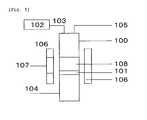
- the grafted resin in the present invention refers to a block polymerized resin and a structure thereof is illustrated in FIG. 2.
- FIG. 2 illustrates a branch-shaped combination of branched side chains from a network polymer as a main chain.
- the grafted resin may include a variety of forms depending upon types of the network polymer or side chain, degree of polymerization, molecular weight, functional groups in the end of molecular chain, the molecular chain or the branched chain, cross-linking degree, and the like.
- the grafted resin may have a variety of performances according to types of the network polymer or side chain, degree of polymerization, molecular weight, or the like.
- the grafted resin used in the present invention is a grafted resin having a hydrophilic group in a side chain.
- a grafted resin having a hydrophilic group in the side chain preferably contains a branched side chain and, even if the network polymer is present in the base layer, the hydrophilic group reaches the surface of the base and hence render the base layer to have wettability.
- a graft-structural resin having a hydrophilic group in a side chain is included in the base resin layer, the surface of the base resin layer is modified and hence become to render a water-dispersed coating solution containing conductive components to be easily and homogeneously applied, without repelling the solution. Consequently, writing sense and input sensitivity is enhanced, thus enabling the supply of conductive laminates having favorable appearance and quality with high productivity.
- the graft-structural resin having a hydrophilic group in a side chain is not included in the base resin layer, due to failures such as unevenness or defect after preparing a conductive laminate, writing sense and input sensitivity cannot be improved.
- the hydrophilic group may include, for example; a hydroxyl group (-OH), a carboxyl group (-COOH), a sulphonic acid group (-SO 3 H), a phosphoric acid group (H 2 PO 4 -), an amino group (-NH 2 ), or the like.
- the grafted resin includes a hydrophilic group in which H + in the hydrophilic group may be in a state partially including a counter-cation such as Na + and K + (that is, -ONa, -COONa, and -SO 3 Na). Meanwhile, such a hydrophilic group may be present alone, or two or more thereof may be present in a branched side chain.
- a copolymer and/or mixture of two grafted resins having different hydrophilic groups may be used.
- the grafted resin having a hydrophilic group in a side chain as described above may include, for example; CHEMTREE (registered trademark) series L-20, L-40M, LH-448, or the like (manufactured by Soken Chemical and Engineering Co. Ltd.).
- the network polymer in the grafted resin used in the present invention may include, for example, polyester resin such as polyethylene terephthalate and polyethylene naphthalate, polycarbonate resin, polyurethane resin, acryl resin, methacryl resin, epoxy resin, polyamide resin, polyimide resin, polyethylene resin, polypropylene resin, polystyrene resin, polyvinyl acetate resin, nylon resin, melamine resin, phenol resin, fluorine resin, and the like.
- the grafted resin may be used alone or as a copolymer and/or mixture of two or more thereof.
- the grafted resin may include a partial cross-linking structure.
- the network polymer of the grafted resin preferably includes a functional group. More preferably, a functional group with reactive properties to form a composite with resins or components contained in the base resin layer, respectively, a functional group compatible with an organic solvent or water, and the like, are present in the network polymer.
- the functional group of the network polymer in the grafted resin may include, for example: a linear alkyl group; a branched alkyl group; a cycloalkyl group; an alkenyl group such as vinyl, aryl, and hexenyl; an aryl group such as phenyl, tollyl, xylyl, styryl, naphthyl, and biphenyl; an aralkyl group such as benzyl and phenetyl; other aromatic groups having heterocyclic rings or their ring-open groups such as lactone, oxazole, and imidazole; an alkoxy group such as methoxy, ethoxy, and isopropoxy; an acetoxy group; an acryl group; a methacryl group; an acryloxy group; a methacryloxy group; an oxycarbonyl group such as aryloxycarbonyl and benzyloxycarbonyl; an epoxy group; an isocyanate group
- hydrophilic groups such as the hydroxyl group, carboxyl group, sulfur group, phosphoric acid group, and amino group
- the functional group of the network polymer in the grafted resin may include at least one randomly selected and used on the basis of use or required characteristics thereof or a mixture of two or more thereof, without being particularly limited to the foregoing.
- the grafted resin contained in the base resin layer may be present in any form in the base resin layer.
- the grafted resin may be contained in a simply mixed state or present as a material having a combination with the urethane acrylate resin or other components in the base resin layer.
- a content of the grafted resin may range from 5% to 90% by weight and, preferably, 10% to 80% by weight, in relation to a total weight of the base resin layer. If it is less than 5% by weight, effects of modifying the surface of the base resin layer may be slight. On the other hand, when the content is more than 90% by weight, a touch panel may occasionally attain only a little improvement in writing sense and input sensitivity, depending upon type or structure of the urethane acrylate resin or bonding form thereof.
- a thickness 'T' of the substrate and a thickness 't' of the base resin layer preferably satisfy the following equations.
- the base resin layer may be easily deformed with high efficiency by the load applied when inputting with a pen or finger, to hence render the touch panel to have more improved writing sense and input sensitivity.
- the t/T value preferably ranges from 0.050 to 0.70.
- the conductive laminate of the present invention comprises stacking a base resin layer and a conductive layer, in sequential order of the base resin layer and the conductive layer from the substrate side. If the conductive layer is not contained, conductive properties are not exhibited.
- the component in the conductive layer preferably has a linear structure.
- the linear structure may include, for example; a fiber-shaped conductor, a needle-shaped conductor such as whisker.
- the length of the short axis may range from 1 nm to 1,000 nm (1 ⁇ m).
- the linear structure may be used alone, or in combination of plural structures as a mixture.
- alternative micro to nano-sized conductive materials may be added thereto, as required.
- the fiber-shaped conductor may include a carbon-based fiber conductor, a metal-based fiber conductor, a metal oxide-based fiber conductor, or the like.
- the carbon-based fiber conductor may include polyacrylonitrile-based carbon fibers, pitch-based carbon fibers, rayon-based carbon fibers, glass-shaped carbon, carbon nanotube, carbon nanocoil, carbon nanowire, carbon nanofiber, carbon whisker, graphite fibril, and the like.
- the metal-based fiber conductor may include fiber-shaped or nanowire-shaped metals or alloys thereof, which are prepared by using, for example; gold, platinum, silver, nickel, silicon, stainless steel, copper, brass, aluminum, zirconium, hafnium, vanadium, niobium, tantalum, chromium, molybdenum, manganese, technetium, rhenium, iron, osmium, cobalt, zinc, scandium, boron, gallium, indium, silicon (silicium), germanium, tin, magnesium, or the like.
- the metal oxide-based fiber conductor may include fiber-shaped or nanowire-shaped metal oxides and/or metal oxide composites, which are prepared by using InO 2 , InO 2 Sn, SnO 2 , ZnO, SnO 2 -Sb 2 O 4 , SnO 2 -V 2 O 5 , TiO 2 (Sn/Sb)O 2 , SiO 2 (Sn/Sb)O 2 , K 2 O-nTiO 2 -(Sn/Sb)O 2 , K 2 O-nTiO 2 -C, and the like.
- the fiber-shaped conductor may also be subjected to surface treatment.
- the fiber-shaped conductor may further include a material prepared by coating or vapor-depositing the surface of a non-metal material such as a plant fiber, a synthetic fiber, or an inorganic fibers with, for example; gold, platinum, silver, nickel, silicon, stainless steel, copper, brass, aluminum, zirconium, hafnium, vanadium, niobium, tantalum, chromium, molybdenum, manganese, technetium, rhenium, iron, osmium, cobalt, zinc, scandium, boron, gallium, indium, silicon, germanium, tin, magnesium, InO 2 , InO 2 Sn, SnO 2 , ZnO, SnO 2 -Sb 2 O 4 , SnO 2 -V 2 O 5 , TiO 2 (Sn/Sb)O 2 , SiO 2 (Sn/Sb)O 2 , K 2 O-nTiO 2 -(Sn/Sb)O
- the conductive laminate of the present invention preferably uses carbon nanotubes as the fiber-shaped conductor, in view of optical properties such as transparency and conductivity.
- the carbon nanotube used in the component of the conductive layer may be any one among a single-layer carbon nanotube, a double-layer carbon nanotube, triple-layer or more carbon nanotubes.
- the nanotube is preferably one having a diameter ranging from 0.3 to 100 nm and a length ranging from about 0.1 to 20 ⁇ m.
- a single-layer carbon nanotube or double-layer carbon nanotube having a diameter of 10 nm or less and a length in the range of 1 to 10 ⁇ m is more preferably used.
- a carbon nanotube assembly contains as few impurities as possible such as amorphous carbon or catalyst metals. If such impurities are contained in the carbon nanotube, purification may be suitably executed by acid treatment or heating.
- the carbon nanotube may be synthesized and produced through arc discharge, laser ablation, catalytic chemical vapor deposition (a method that uses a catalyst including a carrier and a transition metal supported thereby, among chemical vapor deposition methods), or the like. According to the catalytic chemical vapor deposition having excellent productivity and decreasing generation of impurities such as amorphous carbon, carbon nanotubes may be preferably prepared.
- carbon nanotube dispersion may be applied to form a conductive layer.
- the carbon nanotube dispersion is generally prepared by dispersing carbon nanotubes as well as a solvent through a mixer or an ultrasonic irradiation apparatus. Furthermore, any dispersant is preferably added thereto.
- Such a dispersant may be selected from natural polymers and synthetic polymers, in aspects of: adhesiveness to a substrate of a conductive layer containing carbon nanotubes, which are prepared by applying carbon nanotube dispersion to the substrate and drying the same; film hardness; scratch resistance. Further, a cross-linking agent may also be added thereto, without departing from a range in which dispersibility is not deteriorated.
- the synthetic polymer may include, for example; polyetherdiol, polyesterdiol, polycarbonatediol, polyvinyl alchol, partially-saponified polyvinyl alcohol, acetoacetyl group-modified polyvinyl alcohol, acetal group-modified polyvinyl alcohol, butyral group-modified polyvinyl alcohol, silanol group-modified polyvinyl alcohol, ethylene vinyl alcohol copolymer, ethylene vinyl alcohol-vinyl acetate copolymer resin, dimethylamino ethyl acrylate, dimethylamino ethyl methacrylate, acryl resin, epoxy resin, modified epoxy resin, phenoxy resin, modified phenoxy resin, phenoxy ether resin, phenoxy ester resin, fluorine resin, melamine resin, alkyd resin, phenol resin, polyacrylamide, polyacrylic acid, polysthylene sulfonic acid, polyethyleneglycol, polyvinyl pyrrolidone,
- the natural polymers may be selected from, for example; polysaccharides such as starch, pullulan, dextran, dextrin, guar-gum, xanthan gum, amylose, amylopectin, alginic acid, Arabic gum, carageenan, chondroitin sulfate, hyaluronic acid, curdlan, chitin, chitosan, cellulose, and derivatives thereof.
- the derivative may refer to a compound known in the art such as ester and ether.
- the foregoing materials may be used alone or as a mixture of two or more thereof.
- polysaccharides and their derivatives are preferably used since they have excellent dispersible properties in relation to carbon nanotubes.
- cellulose and its derivatives have high film formation ability, thus being preferable.
- ester or ether derivatives are more preferably used.
- carboxymethyl cellulose or salts thereof are suitably used.
- a mixing ratio of the carbon nanotubes and the dispersant is adjustable.
- the mixing ratio between the carbon nanotubes and the dispersant is preferably determined within a range in which it does not incur problems in adhesiveness to a substrate, hardness, scratch resistance, or the like.
- the carbon nanotubes are preferably present in the range of 10 through 90% by weight in relation to a total weight of the conductive layer. More preferably, the carbon nanotubes are contained in the range of 30 to 70% by weight. If an amount of the carbon nanotubes is 10% or more by weight, conductivity required for a touch panel may be easily attained.
- it may be easily and homogeneously applied thereto without repelling.
- a conductive laminate with favorable external appearance and quality may be supplied with high conductivity.
- the carbon nanotubes may have good dispersibility in a solvent and a difficulty in aggregation, and may easily form a favorable carbon nanotube coating layer and attain high conductivity, thereby being preferable.
- a coating film may be rigid and hence hardly incur scratch defects in the manufacturing process, and may uniformly retain surface resistance, thereby being preferable.
- the needle-shaped conductor may include a compound including a metal, carbon compound, metal compound, or the like.
- the metal may include, for example, elements belonging in Group IIA, IIIA, IVA, VA, VIA, VIIA, VIII, IB, IIB, IIIB, IVB or VB in the standard periodic table of chemical elements.
- More particular examples are gold, platinum, silver, nickel, stainless steel, copper, brass, aluminum, gallium, zirconium, hafnium, vanadium, niobium, tantalum, chromium, molybdenum, manganese, antimony, palladium, bismuth, technetium, rhenium, iron, osmium, cobalt, zinc, scandium, boron, gallium, indium, silicon, germanium, tellurium, tin, magnesium, and alloys containing the same.
- the carbon compound may include carbon nanohorn, fullerene, graphene, and the like.
- the metal oxide may include InO 2 , InO 2 Sn, SnO 2 , ZnO, SnO 2 -Sb 2 O 4 , SnO 2 -V 2 O 5 , TiO 2 (Sn/Sb)O 2 , SiO 2 (Sn/Sb)O 2 , K 2 O-nTiO 2 -(Sn/Sb)O 2 , K 2 O-nTiO 2 -C, and the like.
- the conductive laminate of the present invention preferably includes silver nanowires as a needle-shaped conductor, in view of optical properties such as transparency and conductivity.
- the needle-shaped conductor may include, for example: composite compounds of potassium titanate fibers, tin, and antimony oxides, that is, WK200B, WK300R, WK500 among DENTALL WK Series (manufactured by Otsuka Chemical Co. Ltd.); composite compounds of silicon dioxide fibers, tin, and antimony oxides, that is, TM100 or the like among DENTALL TM Series (manufactured by Otsuka Chemical Co. Ltd.), all of which are commercially available in the market.
- the conductive laminate of the present invention preferably has a surface resistivity at the conductive layer side which is 1 ⁇ ⁇ 10 0 ⁇ / or more, and 1 ⁇ 10 4 ⁇ / or less, more preferably, 1 ⁇ 10 1 ⁇ / or more 1. 5 ⁇ 10 3 . Since the surface resistivity is present in the range of 1 ⁇ 10° ⁇ / or more and 1 ⁇ 10 4 ⁇ / or less, the foregoing laminate is preferably used as a conductive laminate for a touch panel. That is, when it is equal to or more than 1 ⁇ 10 0 ⁇ /, power consumption may be decreased. Further, with 1 ⁇ 10 4 ⁇ / or less, it is possible to reduce influence of errors occurring in reading coordinates of the touch panel.
- the conductive layer stacked thereon may also be modified. Since the conductive layer is modified, an area of a contact face contributing to conduction of current by such modified conductive layer may be increased and, as a result, a total flow rate of current is increased even when a small input load is applied, and hence is presumed that input sensitivity may become excellent.
- the present invention is not particularly limited to the above presumption.
- the conductive laminate of the present invention is preferably a transparent conductive laminate having a total luminous transmittance of 80% or more, on the basis of JIS K7361-1 (1997) when the light is incident at the conductive layer side, as described above. If the conductive laminate of the present invention, which is a transparent conductive laminate, is assembled into a touch panel, the touch panel may exhibit not only favorable writing sense and input sensitivity but also excellent transparency. Further, it is possible to clearly recognize indications on a display mounted on a bottom layer of the touch panel including such a transparent conductive laminate. Transparency described in the present invention may refer to a total luminous transmittance of 80% or more, on the basis of JIS K7361-1 (1997) when the light is incident at the conductive layer side, as described above.
- the total luminous transmittance is preferably 85% or more and, more preferably, 90% or more.
- Methods of increasing the total luminous transmittance may include, for example; increasing the total luminous transmittance of a substrate to be used, considerably decreasing a film thickness of the conductive layer, a method of stacking a transparent protection layer to function as a light interference film, further above the conductive layer provided on the base resin layer, and the like.
- the method of increasing the total luminous transmittance may include a method of decreasing a thickness of the substrate or a method of selecting a substrate made of materials having high total luminous transmittance.
- the conductive laminate of the present invention is preferably fabricated by a process to form a conductive layer on a base resin layer, after the base resin layer is formed on a substrate, in which the base resin layer includes a urethane acrylate resin having a glycol skeleton and a grafted resin having a hydrophilic group in a side chain. More preferably, the conductive laminate of the present invention may include a conductive layer formed by applying water dispersion including carbon nanotubes or silver nanowires and drying the same.
- the substrate and/or individual layers used in the present invention may further include a variety of additives without departing from a range in which effects of the present invention are not inhibited.
- additives for example, organic and/or inorganic micro-particles, a cross-linking agent, flame retardant, a flame retardant support, a heat resistant stabilizer, an anti-oxidant stabilizer, a leveling agent, an slipping enhancer, a conducting agent, an anti-static agent, UV absorber, a light stabilizer, a nucleating agent, dye, filler, a dispersant, and a coupling agent, and the like, may be used.
- the conductive laminate of the present invention may preferably include a protection layer formed on a conductive layer.
- the conductive layer reflects or absorbs light by physical properties of a conductive component itself. Therefore, in order to improve a total luminous transmittance of a transparent conductive laminate including the conductive layer provided on a substrate, a transparent protection layer is provided on the conductive layer, in which the transparent protection layer is prepared of a transparent material to form an optical interference film, and hence, a mean reflectance at a wavelength in the range of 380 to 780 nm at the optical interference film is preferably decreased to 4% or less.
- the wavelength in the range of 380 to 780 nm at the optical interference film side is preferably 3% or less and, more preferably, 2% or less.
- the mean reflectance is 4% or less, a total luminous transmittance of 80% or more may be obtained with high productivity when the conductive laminate is used for a touch panel or the like, thus being preferable. Further, if the transparent protection layer is present, interference fringe occurring due to interference of reflected light between top and bottom of the touch panel illustrated in FIG. 4 while interposing a space 5 therebetween, may be inhibited, thus being preferable.
- the transparent protection layer which forms an optical interference film on the conductive layer, is more preferably a transparent protection film that concurrently functions to improve scratch-resistance of the conductive layer and prevent the conductive component from escaping, in addition to the role of optical interference.
- the transparent protection layer preferably has a lower refractive index than that of the conductive layer. More particularly, the transparent protection layer is preferably used if a difference of its reflective index to the refractive index of the conductive layer is 0.3 or more and, more preferably, 0.4 or more. With regard to the reflective index of the transparent protection layer, when the difference in refractive indexes is 0.3 or more, a control range to render the mean reflectance of the transparent protection layer to 4% or less may be extended and a manufacturing process margin may also be enlarged, thus being preferable.
- the transparent protection layer may include an inorganic compound, an organic compound, and a composite of inorganic and organic compounds and, hence, may include a configuration having hollow therein.
- a single compound may include: inorganic compounds such as silicon oxide, magnesium fluoride, cerium fluoride, lanthanum fluoride, and calcium fluoride; and organic compounds such as polymer containing silicon or fluorine; or the like.
- the composite may include a mixture of: micro-particles having hollow therein, such as silica and acryl; and mono-functional or multi-functional (meth) acrylic acid ester, a siloxane compound, and/or a polymer prepared by polymerization of a monomer component in an organic compound having a perfluoroalkyl group.
- the silicon oxide may include: tetraalkoxysilanes such as tetramethoxysilane, tetraethoxysilane, tetra-n-propoxysilane, tetra-i-propoxysilane, tetra-n-butoxysilane; trialkoxysilanes such as methyl trimethoxysilane, methyl triethoxylsilane, ethyl trimethoxysilane, ethyl triethoxysilane, n-propyl trimethoxysilane, n-propyl triethoxylsilane, i-propyl trimethoxysilane, i-propyl triethoxysilane, n-butyl trimethoxysilane, n-butyl triethoxylsilane, n-pentyl trimethoxysilane, n-pentyl triethoxysilane, n
- the composite using silica micro-particles having hollow therein may include, in particular, OPSTER (registered trademark) TU-2180 (manufactured by JSR Corporation).
- the optimum method may be selected depending upon the material produced therefrom, and general methods such as dry methods such as vacuum deposition, EB deposition, sputtering; wet-coating methods such as casting, spin coating, dip coating, bar coating, spray, blade coating, slit-die coating, gravure coating, reverse coating, screen printing, mold coating, print transfer, and ink-jet may be employed.
- slit-die coating which can uniformly laminate the base resin layer, conductive layer and transparent protection layer while hardly incurring scars on the conductive layer or, otherwise, a wet coating process using a micro-gravure to uniformly form each of the base resin layer, conductive layer and transparent protection layer with high productivity, may be preferably used.
- the conductive laminate of the present invention is preferably fabricated by a method that forms the transparent protection layer in more preferable form on the conductive layer.
- FIG. 4 is a schematic cross-sectional view illustrating one example of a resistive film type touch panel.
- the resistive film type touch panel includes a top electrode 13 secured to a bottom electrode 14 by using a frame-shaped double-sided adhesive tape 19.
- Substrates 15 and 16 form the top and bottom electrodes, respectively, and each may be provided with a base resin layer 2 and a conductive layer 3, which are stacked in sequential order, and the conductive layers 3 of the top and bottom electrodes are opposed to each other while interposing a space 20 therebetween and formed into a facial shape.
- a transparent protection layer 4 may be placed above the conductive layer 3 in the substrate 15 or 16.
- the space 20 may have dot spacers 18 arranged at a constant interval and, hence, a gap between the conductive layers at top and bottom sides may be maintained owing to the foregoing configuration.
- the top surface of the substrate 15 is a face, which comes into contact with a pen 22 or finger tip, and may be provided with a hard coating layer 17 configured to prevent scratch.
- a desired load thereon may render electricity to flow through the contact part.
- the touch panel configured as described above may include, for example, a lead wire and a driving unit, and be combined with a front face of a liquid crystal display and used.
- the resistive film type touch panel illustrated in FIG. 4 is configured while interposing a space 20 therein, so that the base resin layer is deformed by a load applied when inputting with a pen or finger and, hence, writing sense and input sensitivity of the touch panel may be noticeably and effectively improved, thereby resulting in the touch panel configured to attain maximum effects by the use of the conductive laminate of the present invention.
- a sample was immersed in a solvent to delaminate and extract respective layers and the used solvent was filtered after the immersion. If a filtrate is present, a solvent having a high solubility in relation to the filtrate was selected and the filtrate was dissolved again in the solvent.
- the filtrate and the re-dissolved filtrate solution were separated and purified into single materials, respectively. In the case where these materials are combined with other components and entail difficulties in separation, they were used directly.
- each of the materials was suitably concentrated and/or diluted and structural identification was executed by any method suitably selected from nuclear magnetic resonance spectroscopy ( 1 H-NMR, 13 C-NMR), two-dimensional nuclear magnetic resonance spectroscopy (2D-NMR), infrared spectro-photometry (IR), Raman spectroscopy, mass spectrometry (Mass), X-ray diffraction (XRD), neutron diffraction (ND), low-energy electron diffraction (LEED), reflection high-energy electron diffraction (RHEED), atomic absorption spectrometry (AAS), UV photo-electron spectroscopy (UPS), X-ray photo-electron spectroscopy (XPS), X-ray fluorescence analysis (XRF), inductively coupled plasma-atomic emission spectroscopy (ICP-AES), electron probe micro-analyzer (EPMA), gel permeation chromatography (GPC), and other elementary analysis methods, and/or in combination with two or more thereof.
- Grade A R/R 0 ⁇ 1.5 Grade B: 1.5 ⁇ R/R 0 ⁇ 1.8 Grade C: R/R 0 > 1.8
- Grade A R/R 0 ⁇ 1.5
- Grade B 1.5 ⁇ R/R 0 ⁇ 1.8
- Grade C R/R 0 > 1.8
- Each sample was cut off in a direction perpendicular to a plane of the sample, using a rotary microtome with a knife slope angle of 3° (manufactured by Nihon Microtome Laboratory Co. Ltd.).
- the cut side of the prepared sample piece was observed by a scanning electron microscope ABT-32 (manufactured by TOPCON Corporation) in which three magnifications were any ones selected from the observation magnification ranging from 2,500 to 10,000 times, image contrast was suitably adjusted, and the sample was observed at each of the selected magnifications.
- ABT-32 manufactured by TOPCON Corporation
- the surface of a sample at the conductive layer side was observed by using an electric field radiation type scanning electron microscope (trade name: JSM-6700-F, manufactured by JEOL Ltd.) at acceleration voltage of 3.0 kV or, otherwise, an atomic force microscope (trade name: Nano Scope III, manufactured by Digital Instruments).
- an electric field radiation type scanning electron microscope (trade name: JSM-6700-F, manufactured by JEOL Ltd.) at acceleration voltage of 3.0 kV or, otherwise, an atomic force microscope (trade name: Nano Scope III, manufactured by Digital Instruments).
- ON load refers to, for example, a minimum load at which a touch panel firstly displays contact resistance described below and with which the touch panel can be operated, when applying the load to the touch panel with a pen 22 illustrated in FIG. 4 , and hence meaning that the touch panel may be operated with even a small force by which a small ON load is generated.
- the above ON load is an indication of writing sense.
- the contact resistance may refer to a resistance value when applying a load, for example, when electricity flows on a face coming into contact with top and bottom electrodes illustrated in FIG. 4 .
- the contact resistance value is an indication, meaning that, as the contact resistance is decreased, the touch panel may be operated with better input sensitivity.
- ON load and contact resistance value was determined as follows. First, with regard to the touch panel illustrated in FIG. 4 , a touch panel having a dimension of 70 mm (length) ⁇ 100 mm (width) was fabricated by using an ITO-containing conductive glass (manufactured by Touch Panel Laboratories) as the bottom electrode 14, and a conductive laminate in each of the examples according to the invention and the comparative examples as the top electrode. Next, a surface property measurement device HEIDON TRIBOGEAR, type: HEIDON-14 DR (manufactured by Shinto Scientific Co.
- the conductive layer side of the conductive laminate was visibly observed in a 90° direction relative to the conductive side (vertical), 45° direction, and 10° direction, respectively, under a fluorescent lamp.
- a fluorescent lamp As the standards of assessment used in the invention, whether defects of the conductive layer (for example, repelling) are visibly observed was determined, and results thereof were assessed based on the following standards of assessment.
- variation in polarized status of reflected light of the coating film was determined at incident angles of 60°, 65°, and 70°, using a high energy spectroscopic meter M 2000 (manufactured by J. A. Woollam Corporation), and a refractive index at 550 nm was calculated with an analytical soft WVASE 32.
- a film thickness of a transparent protection film in the fabricated transparent conductive laminate was observed at each of any three magnifications by using an electric field radiation type scanning electron microscope (trade name: JSM-6700-F, manufactured by JEOL Ltd.) at acceleration voltage of 3.0 kV, in which three magnifications were randomly selected from the observation magnification ranging from 10, 000 to 200, 000, image contrast was suitably adjusted.
- a cross-section of the sample was adjusted using the microtome described in the above (4). Based on the obtained photographs of the cross-section, any five positions were measured at each of any three magnifications (calculated at a high magnification). From the measured values at total 15 positions, the mean was calculated.
- the mean reflectance was determined according to the following procedure.
- a surface opposed to a transparency measurement face (a face at which the transparent protection layer was provided) was uniformly roughed using No. 320 to 400 water-proof sandpaper to obtain a glossing degree at 60° (JIS Z 8741 (1997)) of 10 or less, and then, coated and colored with a black paint until a visible light transmittance reaches 5% or less.
- a spectrophotometer (trade name: UV-3150, manufactured by Shimadzu Corporation)
- absolute reflectance spectrum in a wavelength region ranging from 300 nm to 800 nm was measured at an interval of 1 nm and with an incident angle of 5° to the measurement face, and the mean reflectance at the wavelength in the range of 380 to 780 nm was determined.
- Resins, photo-polymerization initiators, and films used in the examples and comparative examples are described as follows.
- CHEMITORY registered trademark L-20 (manufactured by Soken Chemical and Engineering Co. Ltd., grafted acryl having a hydroxyl group (-OH) as a hydrophilic group in a side chain, solution with solid content of 26% by weight).
- Aronics registered trademark
- M240 manufactured by TOA GOSEI Co. Ltd., polyethyleneglycol skeleton 2-functional acrylate, solid content of 100% by weight.
- Aronics registered trademark
- M270 manufactured by TOA GOSEI Co. Ltd., polypropyleneglycol skeleton 2-functional acrylate, solid content of 100% by weight
- TRSC-006 Manufactured by Negami Chemical Industrial Co. Ltd., polypropyleneglycol skeleton 2-functional urethane, solution with solid content of 58.8% by weight).
- X-22-8114 manufactured by Shin-Etsu Chemical Co. Ltd., grafted acryl containing silicon with a methyl group (-CH 3 ) or n-butyl group (-CH 2 CH 2 CH 2 CH 3 ) at a side chain, solution with solid content of 40% by weight).
- Ciba IRGACURE (registered trademark) 184 (Ciba Japan Co. Ltd.).
- Conductive layer A carbon nanotube conductive layer
- a vertical fluidized bed reactor illustrated in the schematic view of FIG. 5 was used to synthesize carbon nanotubes.
- a reactor 100 is a cylindrical quartz tube having an inner diameter of 32 mm and a length of 1200 mm.
- a quartz sintered plate 101 is provided in the center of the tube and an inert gas and raw gas supply line 104 is provided at the lower part of the tube while an exhaust gas line 105 and a catalyst loading line 103 are mounted on the upper part of the tube.
- a heater 106 winding around the radius of the reactor is also provided. The heater 106 is provided with an inspection door 107 in order to confirm flow condition in the reactor.
- the temperature was retained and a flow rate of argon from the raw gas supply line 104 was increased to 2000 mL/min to start fluidizing of a solid catalyst on the quartz sintered plate. After confirming the fluidization through the inspection door 107 of the furnace, it started to supply methane to the reactor at 95 mL/min. After feeding the mixed gas for 90 minutes, it was changed into the flow of argon gas alone to terminate the synthesis process.
- a carbon nanotube dispersed coating solution (a mixing ratio of carbon nanotube to dispersant is 1 : 1) containing carbon nanotubes with a concentration of about 0.1% by weight that enables the solution to be applied by a coater.
- the carbon nanotube dispersed coating solution was applied to a quartz glass and dried, thus preparing a carbon nanotube conductive layer having a refractive index of 1.82.
- the carbon nanotube dispersed coating solution was applied by means of a micro-gravure coater (gravure line No. 100R or 150R, gravure rotation rate of 80%) and dried at 100°C for 1 minutes, thus forming a carbon nanotube coating film.
- a micro-gravure coater gravure line No. 100R or 150R, gravure rotation rate of 80%
- Conductive layer B Silicon nanowire conductive layer
- Example 1 of WO 2007/022226 synthesis of silver nanowire
- silver nanowires were obtained.
- Example 8 of WO 2007/022226 dispersed coating solution was prepared.
- This silver nanowire dispersed coating solution was applied by using a bar coater (manufactured by Matsuo Sangyo Co., Ltd.) and dried at 120°C for 2 minutes, thus forming a silver nanowire coating film.
- an ITO conductive thin film having a thickness of 250 nm was formed by a sputtering process at a vacuum degree of 10 -4 Torr and under introduction of argon/oxygen mixed gas.
- Transparent protection layers used in the examples and comparative examples are described below.
- the transparent protection layer was stacked on the conductive layer according to any of methods described in the examples and comparative examples.
- a 'film' having a thickness of 188 ⁇ m was used as a substrate, KAYANOVA (registered trademark) FOP 1740 (manufactured by Nippon Kayaku Co., Ltd., solid content of 82% by weight) was diluted with toluene and methylethylketone at a ratio by weight of 1 : 1, to the solid content of 40% by weight and hence prepare a hard coating agent, the hard coating agent was applied to one face of the substrate by a micro-gravure coater (gravure line No. 80R, gravure rotation rate 100%) and dried at 80°C for 1 minute, followed by UV irradiation at 1.0 J/cm 2 and curing to thereby form a hard coating layer having a thickness of 5 ⁇ m.
- KAYANOVA registered trademark
- FOP 1740 manufactured by Nippon Kayaku Co., Ltd., solid content of 82% by weight
- a base resin layer coating solution 1.40 g of 'resin A', 13.85 g of 'resin B', and 2. 00 g of ethyl acetate were mixed and agitated to prepare a base resin layer coating solution.
- a bar coater No. 30 manufactured by Matsuo Sangyo Co. , Ltd.
- the coating solution was applied to the other face opposed to the face of the substrate, on which the hard coating layer was provided, followed by heating and drying at 100°C for 3 minutes, thereby forming a base resin layer having a coating thickness of 13 ⁇ m after drying.
- a base resin layer coating solution has the constitutional composition of; 1.40 g of 'resin A', 13.96 g of 'resin B', 0.041 g of 'photo-polymerization initiator', and 2. 08 g of ethyl acetate and, after applying and drying a coating solution, UV ray was radiated at 1.2 J/cm 2 , the sample procedure as described in Example 1 was executed and 'conductive layer A' was stacked on the base resin layer having a coating thickness of 13 ⁇ m after drying, by gravure line No. 150R, thus resulting in a conductive laminate.
- a 'film' having a thickness of 188 ⁇ m was used as a substrate, KAYANOVA (registered trademark) FOP 1740 (manufactured by Nippon Kayaku Co., Ltd., solid content of 82% by weight) was diluted with toluene and methylethylketone at a ratio by weight of 1 : 1, to the solid content of 40% by weight and hence prepare a hard coating agent, the hard coating agent was applied to one face of the substrate by a micro-gravure coater (gravure line No. 80R, gravure rotation rate 100%) and dried at 80°C for 1 minute, followed by UV irradiation at 1.0 J/cm 2 and curing to thereby form a hard coating layer having a thickness of 5 ⁇ m.
- KAYANOVA registered trademark
- FOP 1740 manufactured by Nippon Kayaku Co., Ltd., solid content of 82% by weight
- a base resin layer coating solution 3.48 g of 'resin A', 8.92 g of 'resin B', and 7.59 g of ethyl acetate were mixed and agitated to prepare a base resin layer coating solution.
- a bar coater No. 30 manufactured by Matsuo Sangyo Co. , Ltd.
- the base resin layer coating solution was applied to the other face opposed to the face of the substrate, on which the hard coating layer was provided, followed by heating and drying at 100°C for 3 minutes, thereby forming a base resin layer having a coating thickness of 13 ⁇ m after drying.
- a 'film' having a thickness of 125 ⁇ m was used as a substrate, KAYANOVA (registered trademark).
- FOP 1740 manufactured by Nippon Kayaku Co., Ltd., solid content of 82% by weight
- FOP 1740 was diluted with toluene and methylethylketone at a ratio by weight of 1 : 1, to the solid content of 40% by weight and hence prepare a hard coating agent
- the hard coating agent was applied to one face of the substrate by a micro-gravure coater (gravure line No. 80R, gravure rotation rate 100%) and dried at 80°C for 1 minute, followed by UV irradiation at 1.0 J/cm 2 and curing to thereby form a hard coating layer having a thickness of 5 ⁇ m.
- a base resin layer coating solution 3.64 g of 'resin A', 1. 38 g of 'resin B', and 14.97 g of ethyl acetate were mixed and agitated to prepare a base resin layer coating solution.
- a bar coater No. 24 manufactured by Matsuo Sangyo Co. , Ltd.
- the base resin layer coating solution was applied to the other face opposed to the face of the substrate, on which the hard coating layer was provided, followed by heating and drying at 100°C for 3 minutes, thereby forming a base resin layer having a coating thickness of 7 ⁇ m after drying.
- 'conductive layer B' was stacked on the base resin layer, thus resulting in a conductive laminate of the invention.
- Example 4 The same procedure as described in Example 4 was executed and 'conductive layer B' was stacked on a base resin layer having a thickness of 7 ⁇ m after drying, except that the base resin layer coating solution has the constitutional composition of; 3. 84 g of 'resin A' , 0. 62 g of 'resin B' , and 15. 55 g ethyl acetate, thus resulting in a conductive laminate of the invention.
- a 'film' having a thickness of 125 ⁇ m was used as a substrate, KAYANOVA (registered trademark) FOP 1740 (manufactured by Nippon Kayaku Co., Ltd., solid content of 82% by weight) was diluted with toluene and methylethylketone at a ratio by weight of 1 : 1, to the solid content of 40% by weight and hence prepare a hard coating agent, the hard coating agent was applied to one face of the substrate by a micro-gravure coater (gravure line No. 80R, gravure rotation rate 100%) and dried at 80°C for 1 minute, followed by UV irradiation at 1.0 J/cm 2 and curing to thereby form a hard coating layer having a thickness of 5 ⁇ m.
- KAYANOVA registered trademark
- FOP 1740 manufactured by Nippon Kayaku Co., Ltd., solid content of 82% by weight
- a base resin layer coating solution 1.40 g of 'resin A', 13.96 g of 'resin B', 0.041 g of 'photo-polymerization initiator', and 9.95 g of ethyl acetate were mixed and agitated to prepare a base resin layer coating solution.
- a bar coater No. 24 manufactured by Matsuo Sangyo Co., Ltd.
- the base resin layer coating solution was applied to the other face opposed to the face of the substrate, on which the hard coating layer was provided, heated and dried at 100°C for 3 minutes, followed by UV irradiation at 1.2 J/cm 2 and curing, thereby forming a base resin layer having a coating thickness of 7 ⁇ m.
- a base resin layer coating solution has the constitutional composition of; 1.80 g of 'resin A', 8.48 g of 'resin B', 0.043 g of 'photo-polymerization initiator', and 9.92 g of ethyl acetate and after applying and drying a coating solution, UV ray was radiated at 1.2 J/cm 2 , the sample procedure as described in Example 6 was executed and 'conductive layer A' was stacked on the base resin layer having a coating thickness of 7 ⁇ m, by gravure line No. 150R, thus resulting in a conductive laminate of the invention.
- a base resin layer coating solution has the constitutional composition of; 1.00 g of 'resin A', 16.40 g of 'resin B', 0.030 g of 'photo-polymerization initiator', and 9.04 g of ethyl acetate and after applying and drying a coating solution, UV ray was radiated at 1.2 J/cm 2 , the sample procedure as described in Example 6 was executed and 'conductive layer A' was stacked on the base resin layer having a coating thickness of 7 ⁇ m, by gravure line No. 150R, thus resulting in a conductive laminate of the invention.
- a base resin layer coating solution has the constitutional composition of; 0.80 g of 'resin A', 18.90 g of 'resin B', 0.024 g of 'photo-polymerization initiator', and 8.97 g of ethyl acetate and after applying and drying a coating solution, UV ray was radiated at 1.2 J/cm 2 , the sample procedure as described in Example 6 was executed and 'conductive layer A' was stacked on the base resin layer having a coating thickness of 7 ⁇ m, by gravure line No. 150R, thus resulting in a conductive laminate of the invention.
- a 'film' having a thickness of 125 ⁇ m was used as a substrate, KAYANOVA (registered trademark) FOP 1740 (manufactured by Nippon Kayaku Co., Ltd., solid content of 82% by weight) was diluted with toluene and methylethylketone at a ratio by weight of 1 : 1, to the solid content of 40% by weight and hence prepare a hard coating agent, the hard coating agent was applied to one face of the substrate by a micro-gravure coater (gravure line No. 80R, gravure rotation rate 100%) and dried at 80°C for 1 minute, followed by UV irradiation at 1.0 J/cm 2 and curing to thereby form a hard coating layer having a thickness of 5 ⁇ m.
- KAYANOVA registered trademark
- FOP 1740 manufactured by Nippon Kayaku Co., Ltd., solid content of 82% by weight
- a base resin layer coating solution 0.50 of 'resin A', 19.44 g of 'resin B', 0.015 g of 'photo-polymerization initiator', and 0.67 g of ethyl acetate were mixed and agitated to prepare a base resin layer coating solution.
- a bar coater No. 26 manufactured by Matsuo Sangyo Co. , Ltd.
- the base resin layer coating solution was applied to the other face opposed to the face of the substrate, on which the hard coating layer was provided, heated and dried at 100°C for 3 minutes, followed by UV irradiation at 1.2 J/cm 2 and curing, thereby forming a base resin layer having a coating thickness of 10.5 ⁇ m.
- a 'film' having a thickness of 125 ⁇ m was used as a substrate, KAYANOVA (registered trademark) FOP 1740 (manufactured by Nippon Kayaku Co., Ltd., solid content of 82% by weight) was diluted with toluene and methylethylketone at a ratio by weight of 1 : 1, to the solid content of 40% by weight and hence prepare a hard coating agent, the hard coating agent was applied to one face of the substrate by a micro-gravure coater (gravure line No. 80R, gravure rotation rate 100%) and dried at 80°C for 1 minute, followed by UV irradiation at 1.0 J/cm 2 and curing to thereby form a hard coating layer having a thickness of 5 ⁇ m.
- KAYANOVA registered trademark
- FOP 1740 manufactured by Nippon Kayaku Co., Ltd., solid content of 82% by weight
- a base resin layer coating solution 1.00 of 'resin A', 9.89 g of 'resin B', 0. 030 g of 'photo-polymerization initiator', and 7.09 g of ethyl acetate were mixed and agitated to prepare a base resin layer coating solution.
- a bar coater No. 16 manufactured by Matsuo Sangyo Co., Ltd.
- the base resin layer coating solution was applied to the other face opposed to the face of the substrate, on which the hard coating layer was provided, heated and dried at 100°C for 3 minutes, followed by UV irradiation at 1.2 J/cm 2 and curing, thereby forming a base resin layer having a coating thickness of 4.8 ⁇ m.
- Example 11 The same procedure as described in Example 11 was executed to form a conductive laminate of the invention, except that 'conductive layer A' to be laminated was stacked by gravure line No. 100R.
- 'Transparent protection layer material A' coating solution having a solid content of 1.0% by weight was applied to 'conductive layer A' in Example 6 by a micro-gravure coater (gravure line No. 80R, gravure rotation rate 100%), followed by drying at 125°C for 1 minute to form a transparent protection layer having a thickness of 60 nm, resulting in a conductive laminate of the invention.
- a micro-gravure coater gravure line No. 80R, gravure rotation rate 100%
- 'Transparent protection layer material A' coating solution having a solid content of 1.2% by weight was applied to 'conductive layer A' in Example 6 by a micro-gravure coater (gravure line No. 80R, gravure rotation rate 100%), followed by drying at 125°C for 1 minute to form a transparent protection layer having a thickness of 75 nm, resulting in a conductive laminate of the invention.
- a micro-gravure coater gravure line No. 80R, gravure rotation rate 100%
- 'Transparent protection layer material A' coating solution having a solid content of 1.5% by weight was applied to 'conductive layer A' in Example 6 by a micro-gravure coater (gravure line No. 80R, gravure rotation rate 100%), followed by drying at 125°C for 1 minute to form a transparent protection layer having a thickness of 100 nm, resulting in a conductive laminate of the invention.
- a micro-gravure coater gravure line No. 80R, gravure rotation rate 100%
- 'Transparent protection layer material B' coating solution having a solid content of 1.5% by weight was applied to 'conductive layer A' in Example 6 by a micro-gravure coater (gravure line No. 120R, gravure rotation rate 100%) and dried at 80°C for 30 seconds, followed by UV irradiation at 1.2 J/cm 2 and curing to form a transparent protection layer having a thickness of 65 nm, resulting in a conductive laminate of the invention.
- a micro-gravure coater gravure line No. 120R, gravure rotation rate 100%
- 'Transparent protection layer material B' coating solution having a solid content of 1.5% by weight was applied to 'conductive layer A' in Example 6 by a micro-gravure coater (gravure line No. 80R, gravure rotation rate 100%) and dried at 80°C for 30 seconds, followed by UV irradiation at 1.2 J/cm 2 and curing to form a transparent protection layer having a thickness of 100 nm, resulting in a conductive laminate of the invention.
- a micro-gravure coater gravure line No. 80R, gravure rotation rate 100%
- a 'film' having a thickness of 188 ⁇ m was used as a substrate, KAYANOVA (registered trademark) FOP 1740 (manufactured by Nippon Kayaku Co., Ltd., solid content of 82% by weight) was diluted with toluene and methylethylketone at a ratio by weight of 1 : 1, to the solid content of 40% by weight and hence prepare a hard coating agent, the hard coating agent was applied to one face of the substrate by a micro-gravure coater (gravure line No. 80R, gravure rotation rate 100%) and dried at 80°C for 1 minute, followed by UV irradiation at 1.0 J/cm 2 and curing to thereby form a hard coating layer having a thickness of 5 ⁇ m. Then, a laminate was prepared without a base resin layer and a conductive layer provided on the other face opposed to the face of the substrate, on which a hard coating layer is provided.
- KAYANOVA registered trademark
- FOP 1740 manufactured by Nippon
- a 'film' having a thickness of 188 ⁇ m was used as a substrate, KAYANOVA (registered trademark) FOP 1740 (manufactured by Nippon Kayaku Co., Ltd., solid content of 82% by weight) was diluted with toluene and methylethylketone at a ratio by weight of 1 : 1, to the solid content of 40% by weight and hence prepare a hard coating agent, the hard coating agent was applied to one face of the substrate by a micro-gravure coater (gravure line No. 80R, gravure rotation rate 100%) and dried at 80°C for 1 minute, followed by UV irradiation at 1.0 J/cm 2 and curing to thereby form a hard coating layer having a thickness of 5 ⁇ m.
- KAYANOVA registered trademark
- FOP 1740 manufactured by Nippon Kayaku Co., Ltd., solid content of 82% by weight
- a base resin layer coating solution 5.80 g of 'resin A', 0.174 g of 'photo-polymerization initiator' , and 14.63 g of ethyl acetate were mixed and agitated to prepare a base resin layer coating solution.
- a bar coater No. 30 manufactured by Matsuo Sangyo Co., Ltd.
- the base resin layer coating solution was applied to the other face opposed to the face of the substrate, on which the hard coating layer was provided, heated and dried at 100°C for 3 minutes, followed by UV irradiation at 1.2 J/cm 2 and curing, thereby forming only a base resin layer having a coating thickness of 13 ⁇ m and, which in turn, resulting in a laminate without a conductive layer.
- a 'film' having a thickness of 188 ⁇ m was used as a substrate, KAYANOVA (registered trademark) FOP 1740 (manufactured by Nippon Kayaku Co., Ltd., solid content of 82% by weight) was diluted with toluene and methylethylketone at a ratio by weight of 1 : 1, to the solid content of 40% by weight and hence prepare a hard coating agent, the hard coating agent was applied to one face of the substrate by a micro-gravure coater (gravure line No. 80R, gravure rotation rate 100%) and dried at 80°C for 1 minute, followed by UV irradiation at 1.0 J/cm 2 and curing to thereby form a hard coating layer having a thickness of 5 ⁇ m.
- KAYANOVA registered trademark
- FOP 1740 manufactured by Nippon Kayaku Co., Ltd., solid content of 82% by weight
- 'conductive layer C' was directly stacked on the other face opposed to the face of the substrate, on which the hard coating layer is provided, without a base resin layer, to thereby form a conductive laminate.
- Example 2 The same procedure as described in Example 1 was executed and 'conductive layer A' was stacked on a base resin layer having a coating thickness of 13 ⁇ m after drying by gravure line No. 150R, to form a conductive laminate, except that a resin to be used in the base resin layer coating solution was 'resin C'.
- Example 2 The same procedure as described in Example 2 was executed and 'conductive layer A' was stacked on a base resin layer having a coating thickness of 13 ⁇ m after drying by gravure line No. 150R, to form a conductive laminate, except that a resin to be used in the base resin layer coating solution was 'resin D'.
- Example 28 The same procedure as described in Example 28 was executed and 'conductive layer A' was stacked on a base resin layer having a coating thickness of 13 ⁇ m after drying by gravure line No. 150R, to form a conductive laminate, except that a resin to be used in the base resin layer coating solution was 'resin E'.
- a 'film' having a thickness of 188 ⁇ m was used as a substrate, KAYANOVA (registered trademark) FOP 1740 (manufactured by Nippon Kayaku Co., Ltd., solid content of 82% by weight) was diluted with toluene and methylethylketone at a ratio by weight of 1 : 1, to the solid content of 40% by weight and hence prepare a hard coating agent, the hard coating agent was applied to one face of the substrate by a micro-gravure coater (gravure line No. 80R, gravure rotation rate 100%) and dried at 80°C for 1 minute, followed by UV irradiation at 1.0 J/cm 2 and curing to thereby form a hard coating layer having a thickness of 5 ⁇ m.
- KAYANOVA registered trademark
- FOP 1740 manufactured by Nippon Kayaku Co., Ltd., solid content of 82% by weight
- 'resin F' 1.00 g of 'resin F', 5.82 g of 'resin B', and 0.43 g of ethyl acetate were mixed and agitated to prepare a base resin layer coating solution.
- a bar coater No. 30 manufactured by Matsuo Sangyo Co. , Ltd.
- the base resin layer coating solution was applied to the other face opposed to the face of the substrate, on which the hard coating layer was provided, heated and dried at 100°C for 3 minutes, to thereby form a base resin layer having a coating thickness of 13 ⁇ m after drying.
- a 'film' having a thickness of 188 ⁇ m was used as a substrate, KAYANOVA (registered trademark) FOP 1740 (manufactured by Nippon Kayaku Co., Ltd., solid content of 82% by weight) was diluted with toluene and methylethylketone at a ratio by weight of 1 : 1, to the solid content of 40% by weight and hence prepare a hard coating agent, the hard coating agent was applied to one face of the substrate by a micro-gravure coater (gravure line No. 80R, gravure rotation rate 100%) and dried at 80°C for 1 minute, followed by UV irradiation at 1.0 J/cm 2 and curing to thereby form a hard coating layer having a thickness of 5 ⁇ m.
- KAYANOVA registered trademark
- FOP 1740 manufactured by Nippon Kayaku Co., Ltd., solid content of 82% by weight
- a base resin layer coating solution 1.00 g of 'resin F', 3.87 g of 'resin G', and 2.46 g of ethyl acetate were mixed and agitated to prepare a base resin layer coating solution.
- a bar coater No. 30 manufactured by Matsuo Sangyo Co., Ltd.
- the base resin layer coating solution was applied to the other face opposed to the face of the substrate, on which the hard coating layer was provided, heated and dried at 100°C for 3 minutes, to thereby form a base resin layer having a coating thickness of 13 ⁇ m after drying.
- Examples 1 to 17 it was possible to enhance writing sense and input sensitivity of a touch panel.
- a base resin layer was prepared by mixing an urethane acrylate, in which a glycol skeleton has a specific structure and the number of functional groups at an acrylate part is 2, as well as a grafted resin having a hydrophilic group in a side chain (Examples 1 to 3, 6, and 13 to 17)
- water dispersion including a conductive component with a linear structure could be applied and, in addition, writing sense and input sensitivity were remarkably enhanced.
- the acrylate part of the urethane acrylate resin was combined with another acrylate part (Examples 2, 6, and 13 to 17), favorable durability was successfully achieved.
- a touch panel does not act. If a base resin layer was not provided (Comparative Examples 3 to 5), it exhibited poor writing sense and input sensitivity.
- a skeleton structure of an urethane acrylate resin in a base resin layer is not a glycol skeleton (Comparative Examples 6 and 7) or, otherwise, even though a grycol skeleton is present, the material having the above structure is not an urethane acrylate (Comparative Examples 8, 9, and 10), writing sense and input sensitivity were deteriorated.
- a side chain of a grafted resin is a hydrophobic group, a water dispersed coating solution may not be applied, thus causing a failure in laminating a conductive layer (Comparative Example 11).
- the invention provides a conductive laminate with good writing sense and high input sensitivity to a touch panel, and favorable durability. Further, the conductive laminate may be used for electrode members, which are employed in display-related products such as a liquid crystal display, an organic electro-luminescence, and/or an electronic paper, a solar cell module, and the like.
Landscapes
- Engineering & Computer Science (AREA)
- Manufacturing & Machinery (AREA)
- Laminated Bodies (AREA)
- Position Input By Displaying (AREA)
- Non-Insulated Conductors (AREA)
- Manufacturing Of Electric Cables (AREA)
- Electroluminescent Light Sources (AREA)
Applications Claiming Priority (2)
| Application Number | Priority Date | Filing Date | Title |
|---|---|---|---|
| JP2009257833 | 2009-11-11 | ||
| PCT/JP2010/069405 WO2011058898A1 (fr) | 2009-11-11 | 2010-11-01 | Stratifié électroconducteur et procédé de fabrication de ce dernier |
Publications (2)
| Publication Number | Publication Date |
|---|---|
| EP2500170A1 true EP2500170A1 (fr) | 2012-09-19 |
| EP2500170A4 EP2500170A4 (fr) | 2014-04-02 |
Family
ID=43991557
Family Applications (1)
| Application Number | Title | Priority Date | Filing Date |
|---|---|---|---|
| EP20100829858 Withdrawn EP2500170A4 (fr) | 2009-11-11 | 2010-11-01 | Stratifié électroconducteur et procédé de fabrication de ce dernier |
Country Status (7)
| Country | Link |
|---|---|
| US (1) | US20120231248A1 (fr) |
| EP (1) | EP2500170A4 (fr) |
| JP (1) | JP5423784B2 (fr) |
| KR (1) | KR20120101381A (fr) |
| CN (1) | CN102574388B (fr) |
| TW (1) | TW201126547A (fr) |
| WO (1) | WO2011058898A1 (fr) |
Cited By (1)
| Publication number | Priority date | Publication date | Assignee | Title |
|---|---|---|---|---|
| WO2018172269A1 (fr) | 2017-03-21 | 2018-09-27 | Basf Se | Film électroconducteur comprenant des nano-objets |
Families Citing this family (32)
| Publication number | Priority date | Publication date | Assignee | Title |
|---|---|---|---|---|
| JP2012033466A (ja) * | 2010-07-02 | 2012-02-16 | Fujifilm Corp | 導電層転写材料、及びタッチパネル |
| CN103123547A (zh) * | 2011-11-16 | 2013-05-29 | 宸鸿科技(厦门)有限公司 | 光学面板的堆叠结构及其制造方法 |
| EP2765490B1 (fr) * | 2011-12-16 | 2017-06-07 | FUJIFILM Corporation | Feuille conductrice et panneau tactile |
| TWI460644B (zh) * | 2012-01-06 | 2014-11-11 | Egalax Empia Technology Inc | 薄型電容式觸摸屏 |
| TWI611920B (zh) * | 2012-01-27 | 2018-01-21 | 第一毛織股份有限公司 | 用於窗片之層合物、含有該層合物之窗片以及含有該層合物之顯示裝置 |
| CN103325441A (zh) * | 2012-03-21 | 2013-09-25 | 宸鸿科技(厦门)有限公司 | 触控面板之导电薄膜及其制造方法 |
| JP5899145B2 (ja) * | 2012-06-18 | 2016-04-06 | 富士フイルム株式会社 | インプリント用下層膜形成組成物およびパターン形成方法 |
| US20150243405A1 (en) * | 2012-09-27 | 2015-08-27 | Toray Industries, Inc. | Transparent conductive laminate |
| CN103838440B (zh) * | 2012-11-23 | 2016-08-10 | 北京富纳特创新科技有限公司 | 触摸屏 |
| CN103838455B (zh) * | 2012-11-23 | 2016-12-21 | 北京富纳特创新科技有限公司 | 电阻式触摸屏 |
| JP6289494B2 (ja) * | 2012-12-07 | 2018-03-07 | スリーエム イノベイティブ プロパティズ カンパニー | 導電性物品 |
| KR102148154B1 (ko) * | 2013-01-22 | 2020-08-26 | 주식회사 동진쎄미켐 | 투명 전도성 막 코팅 조성물, 투명 전도성 막 및 투명 전도성 막의 제조 방법 |
| KR20140110539A (ko) | 2013-03-08 | 2014-09-17 | 삼성디스플레이 주식회사 | 표시 장치 |
| JP6089860B2 (ja) * | 2013-03-27 | 2017-03-08 | 凸版印刷株式会社 | 透明導電性フィルム |
| KR102204683B1 (ko) * | 2013-06-07 | 2021-01-19 | 세이코 피엠씨 가부시키가이샤 | 금속 나노 와이어 함유 조성물 |
| KR102035715B1 (ko) | 2013-06-27 | 2019-10-24 | 삼성디스플레이 주식회사 | 액정 표시 장치 |
| US10108305B2 (en) | 2013-08-13 | 2018-10-23 | Samsung Electronics Company, Ltd. | Interaction sensing |
| US10042446B2 (en) | 2013-08-13 | 2018-08-07 | Samsung Electronics Company, Ltd. | Interaction modes for object-device interactions |
| KR20160058745A (ko) * | 2013-10-16 | 2016-05-25 | 히타치가세이가부시끼가이샤 | 도전성 섬유를 포함하는 적층체, 감광성 도전 필름, 도전 패턴의 제조 방법, 도전 패턴 기판, 및 터치 패널 |
| KR101477430B1 (ko) * | 2013-12-30 | 2014-12-29 | 삼성전기주식회사 | 적층 세라믹 전자부품, 그 제조방법 및 적층 세라믹 전자부품의 실장 기판 |
| KR20150084458A (ko) * | 2014-01-14 | 2015-07-22 | 삼성전기주식회사 | 터치 패널 |
| JP6394252B2 (ja) * | 2014-10-03 | 2018-09-26 | コニカミノルタ株式会社 | 透明導電フィルム、その製造方法及びタッチパネル |
| CN104505150A (zh) * | 2014-12-09 | 2015-04-08 | 广州北峻工业材料有限公司 | 一种透明导电膜及其制备方法 |
| CN104575701B (zh) * | 2014-12-17 | 2017-01-11 | 张家港康得新光电材料有限公司 | 高分子透明导电膜及其制备方法 |
| KR20170130175A (ko) * | 2016-05-18 | 2017-11-28 | 삼성전자주식회사 | 셀룰로스 분리막을 제조하는 방법, 그에 의하여 제조된 셀룰로스 분리막 및 그를 포함하는 이차이온전지 |
| EP3401928B1 (fr) * | 2017-05-09 | 2021-08-18 | Henkel AG & Co. KGaA | Adhésif électriquement conducteur pour fixer des cellules solaires |
| JP7378952B2 (ja) * | 2018-04-25 | 2023-11-14 | ナガセケムテックス株式会社 | 透明導電膜を有する光学積層体、及びコーティング組成物 |
| JP7242704B2 (ja) | 2018-04-26 | 2023-03-20 | ヘンケル・アクチェンゲゼルシャフト・ウント・コムパニー・コマンディットゲゼルシャフト・アウフ・アクチェン | 太陽電池を接着するための導電性接着剤 |
| CN110942843A (zh) * | 2019-10-23 | 2020-03-31 | 清远高新华园科技协同创新研究院有限公司 | 电动汽车用高分子导电膜、生产设备及制备方法 |
| KR20210146491A (ko) * | 2020-05-26 | 2021-12-06 | 삼성디스플레이 주식회사 | 이송 복합체 및 이를 포함하는 이송 모듈 |
| CN115776942A (zh) * | 2020-09-29 | 2023-03-10 | 东洋纺株式会社 | 透明导电性薄膜 |
| CN119560233B (zh) * | 2024-12-25 | 2025-10-10 | 太原理工大学 | 一种基于铜银复合纳米管壳的柔性透明导电电极制备方法 |
Family Cites Families (13)
| Publication number | Priority date | Publication date | Assignee | Title |
|---|---|---|---|---|
| JP4306024B2 (ja) * | 1998-06-22 | 2009-07-29 | 東洋紡績株式会社 | 高制電性積層体およびそれを用いた成形品 |
| MY136978A (en) * | 1998-06-22 | 2008-12-31 | Toyo Boseki | Highly antistatic laminate |
| JP2002098803A (ja) * | 2000-09-22 | 2002-04-05 | Fuji Photo Film Co Ltd | 透明導電・反射防止フイルム及びそれを用いた表示装置 |
| WO2003032332A1 (fr) * | 2001-10-05 | 2003-04-17 | Bridgestone Corporation | Film transparent electroconducteur, son procede de fabrication, et ecran tactile y relatif |
| JP2004213990A (ja) * | 2002-12-27 | 2004-07-29 | Toyobo Co Ltd | 透明導電性フィルムおよびタッチパネル |
| JP2007042284A (ja) | 2003-10-27 | 2007-02-15 | Teijin Ltd | 透明導電性積層体及び透明タッチパネル |
| US7196136B2 (en) * | 2004-04-29 | 2007-03-27 | Hewlett-Packard Development Company, L.P. | UV curable coating composition |
| SG150517A1 (en) | 2005-08-12 | 2009-03-30 | Cambrios Technologies Corp | Nanowires-based transparent conductors |
| JP4920318B2 (ja) * | 2006-06-20 | 2012-04-18 | 富士フイルム株式会社 | 導電性パターン形成方法、及びワイヤグリッド型偏光子 |
| JP2008243532A (ja) | 2007-03-27 | 2008-10-09 | Konica Minolta Holdings Inc | 透明導電性フィルム |
| KR101447311B1 (ko) * | 2007-09-20 | 2014-10-06 | 도요보 가부시키가이샤 | 점착시트, 터치패널용 상부전극 및 화상표시장치 |
| JP5266889B2 (ja) * | 2008-06-04 | 2013-08-21 | ソニー株式会社 | 光透過性導電体の製造方法 |
| JP5286960B2 (ja) * | 2008-06-17 | 2013-09-11 | 日油株式会社 | 透明導電性フィルム及びそれを備えるタッチパネル |
-
2010
- 2010-11-01 EP EP20100829858 patent/EP2500170A4/fr not_active Withdrawn
- 2010-11-01 WO PCT/JP2010/069405 patent/WO2011058898A1/fr not_active Ceased
- 2010-11-01 US US13/509,173 patent/US20120231248A1/en not_active Abandoned
- 2010-11-01 KR KR20127012055A patent/KR20120101381A/ko not_active Withdrawn
- 2010-11-01 JP JP2011502185A patent/JP5423784B2/ja not_active Expired - Fee Related
- 2010-11-01 CN CN201080045653.1A patent/CN102574388B/zh not_active Expired - Fee Related
- 2010-11-10 TW TW99138597A patent/TW201126547A/zh unknown
Non-Patent Citations (2)
| Title |
|---|
| No further relevant documents disclosed * |
| See also references of WO2011058898A1 * |
Cited By (1)
| Publication number | Priority date | Publication date | Assignee | Title |
|---|---|---|---|---|
| WO2018172269A1 (fr) | 2017-03-21 | 2018-09-27 | Basf Se | Film électroconducteur comprenant des nano-objets |
Also Published As
| Publication number | Publication date |
|---|---|
| JP5423784B2 (ja) | 2014-02-19 |
| JPWO2011058898A1 (ja) | 2013-03-28 |
| WO2011058898A1 (fr) | 2011-05-19 |
| KR20120101381A (ko) | 2012-09-13 |
| US20120231248A1 (en) | 2012-09-13 |
| CN102574388A (zh) | 2012-07-11 |
| CN102574388B (zh) | 2014-05-14 |
| TW201126547A (en) | 2011-08-01 |
| EP2500170A4 (fr) | 2014-04-02 |
Similar Documents
| Publication | Publication Date | Title |
|---|---|---|
| EP2500170A1 (fr) | Stratifié électroconducteur et procédé de fabrication de ce dernier | |
| JP5445042B2 (ja) | 導電積層体およびそれを用いてなるタッチパネル | |
| KR101811068B1 (ko) | 도전 적층체 및 그것을 이용하여 이루어지는 터치 패널 | |
| CN113874211B (zh) | 透明导电性聚酯薄膜及其用途 | |
| JP5793142B2 (ja) | 導電積層体およびタッチパネル | |
| JP7533216B2 (ja) | ポリエステルフィルムとその用途 | |
| US20190184694A1 (en) | Method and apparatus for forming three-dimensional curved surface on laminated substrate, and three-dimensional curved laminated substrate | |
| WO2011158735A1 (fr) | Film stratifié, procédé de fabrication correspondant et dispositif électronique | |
| WO2014010270A1 (fr) | Corps stratifié conducteur, corps stratifié conducteur à motifs, son procédé de fabrication et panneau tactile l'utilisant | |
| CN109073940B (zh) | 液晶调光构件、透光性导电薄膜、及液晶调光元件 | |
| CN103959397B (zh) | 导电层合体及使用该导电层合体而成的显示体 | |
| JP6866104B2 (ja) | 導電体およびその製造方法、ならびにこれを含む素子 | |
| CN112955321A (zh) | 带印刷层的膜层叠体、包含该膜层叠体的光学层叠体、以及使用了它们的图像显示装置 | |
| JP4900892B2 (ja) | 光学フィルムの作製方法 | |
| TWI814157B (zh) | 光學積層體、物品 | |
| CN111372776A (zh) | 透明导电性薄膜 | |
| JP2013230564A (ja) | 透明導電積層体およびそれを用いてなる表示体 |
Legal Events
| Date | Code | Title | Description |
|---|---|---|---|
| PUAI | Public reference made under article 153(3) epc to a published international application that has entered the european phase |
Free format text: ORIGINAL CODE: 0009012 |
|
| 17P | Request for examination filed |
Effective date: 20120503 |
|
| AK | Designated contracting states |
Kind code of ref document: A1 Designated state(s): AL AT BE BG CH CY CZ DE DK EE ES FI FR GB GR HR HU IE IS IT LI LT LU LV MC MK MT NL NO PL PT RO RS SE SI SK SM TR |
|
| DAX | Request for extension of the european patent (deleted) | ||
| A4 | Supplementary search report drawn up and despatched |
Effective date: 20140305 |
|
| RIC1 | Information provided on ipc code assigned before grant |
Ipc: B32B 27/40 20060101AFI20140227BHEP Ipc: H01B 13/00 20060101ALI20140227BHEP Ipc: H01B 5/14 20060101ALI20140227BHEP |
|
| 17Q | First examination report despatched |
Effective date: 20140714 |
|
| STAA | Information on the status of an ep patent application or granted ep patent |
Free format text: STATUS: THE APPLICATION IS DEEMED TO BE WITHDRAWN |
|
| 18D | Application deemed to be withdrawn |
Effective date: 20160810 |