EP2500172B1 - Verfahren zur Herstellung eines Flächenbauteils - Google Patents
Verfahren zur Herstellung eines Flächenbauteils Download PDFInfo
- Publication number
- EP2500172B1 EP2500172B1 EP20120001374 EP12001374A EP2500172B1 EP 2500172 B1 EP2500172 B1 EP 2500172B1 EP 20120001374 EP20120001374 EP 20120001374 EP 12001374 A EP12001374 A EP 12001374A EP 2500172 B1 EP2500172 B1 EP 2500172B1
- Authority
- EP
- European Patent Office
- Prior art keywords
- accordance
- middle layer
- fibre
- reinforced material
- fiber
- Prior art date
- Legal status (The legal status is an assumption and is not a legal conclusion. Google has not performed a legal analysis and makes no representation as to the accuracy of the status listed.)
- Active
Links
Images

Classifications
-
- B—PERFORMING OPERATIONS; TRANSPORTING
- B32—LAYERED PRODUCTS
- B32B—LAYERED PRODUCTS, i.e. PRODUCTS BUILT-UP OF STRATA OF FLAT OR NON-FLAT, e.g. CELLULAR OR HONEYCOMB, FORM
- B32B38/00—Ancillary operations in connection with laminating processes
- B32B38/06—Embossing
-
- B—PERFORMING OPERATIONS; TRANSPORTING
- B29—WORKING OF PLASTICS; WORKING OF SUBSTANCES IN A PLASTIC STATE IN GENERAL
- B29C—SHAPING OR JOINING OF PLASTICS; SHAPING OF MATERIAL IN A PLASTIC STATE, NOT OTHERWISE PROVIDED FOR; AFTER-TREATMENT OF THE SHAPED PRODUCTS, e.g. REPAIRING
- B29C44/00—Shaping by internal pressure generated in the material, e.g. swelling or foaming ; Producing porous or cellular expanded plastics articles
- B29C44/02—Shaping by internal pressure generated in the material, e.g. swelling or foaming ; Producing porous or cellular expanded plastics articles for articles of definite length, i.e. discrete articles
- B29C44/12—Incorporating or moulding on preformed parts, e.g. inserts or reinforcements
- B29C44/1285—Incorporating or moulding on preformed parts, e.g. inserts or reinforcements the preformed part being foamed
-
- B—PERFORMING OPERATIONS; TRANSPORTING
- B29—WORKING OF PLASTICS; WORKING OF SUBSTANCES IN A PLASTIC STATE IN GENERAL
- B29C—SHAPING OR JOINING OF PLASTICS; SHAPING OF MATERIAL IN A PLASTIC STATE, NOT OTHERWISE PROVIDED FOR; AFTER-TREATMENT OF THE SHAPED PRODUCTS, e.g. REPAIRING
- B29C70/00—Shaping composites, i.e. plastics material comprising reinforcements, fillers or preformed parts, e.g. inserts
- B29C70/04—Shaping composites, i.e. plastics material comprising reinforcements, fillers or preformed parts, e.g. inserts comprising reinforcements only, e.g. self-reinforcing plastics
- B29C70/28—Shaping operations therefor
- B29C70/40—Shaping or impregnating by compression not applied
- B29C70/42—Shaping or impregnating by compression not applied for producing articles of definite length, i.e. discrete articles
-
- B—PERFORMING OPERATIONS; TRANSPORTING
- B29—WORKING OF PLASTICS; WORKING OF SUBSTANCES IN A PLASTIC STATE IN GENERAL
- B29D—PRODUCING PARTICULAR ARTICLES FROM PLASTICS OR FROM SUBSTANCES IN A PLASTIC STATE
- B29D99/00—Subject matter not provided for in other groups of this subclass
- B29D99/001—Producing wall or panel-like structures, e.g. for hulls, fuselages, or buildings
- B29D99/0014—Producing wall or panel-like structures, e.g. for hulls, fuselages, or buildings provided with ridges or ribs, e.g. joined ribs
- B29D99/0017—Producing wall or panel-like structures, e.g. for hulls, fuselages, or buildings provided with ridges or ribs, e.g. joined ribs with filled hollow ridges
-
- B—PERFORMING OPERATIONS; TRANSPORTING
- B29—WORKING OF PLASTICS; WORKING OF SUBSTANCES IN A PLASTIC STATE IN GENERAL
- B29D—PRODUCING PARTICULAR ARTICLES FROM PLASTICS OR FROM SUBSTANCES IN A PLASTIC STATE
- B29D99/00—Subject matter not provided for in other groups of this subclass
- B29D99/001—Producing wall or panel-like structures, e.g. for hulls, fuselages, or buildings
- B29D99/0021—Producing wall or panel-like structures, e.g. for hulls, fuselages, or buildings provided with plain or filled structures, e.g. cores, placed between two or more plates or sheets, e.g. in a matrix
-
- B—PERFORMING OPERATIONS; TRANSPORTING
- B29—WORKING OF PLASTICS; WORKING OF SUBSTANCES IN A PLASTIC STATE IN GENERAL
- B29K—INDEXING SCHEME ASSOCIATED WITH SUBCLASSES B29B, B29C OR B29D, RELATING TO MOULDING MATERIALS OR TO MATERIALS FOR MOULDS, REINFORCEMENTS, FILLERS OR PREFORMED PARTS, e.g. INSERTS
- B29K2025/00—Use of polymers of vinyl-aromatic compounds or derivatives thereof as moulding material
- B29K2025/04—Polymers of styrene
- B29K2025/06—PS, i.e. polystyrene
-
- B—PERFORMING OPERATIONS; TRANSPORTING
- B29—WORKING OF PLASTICS; WORKING OF SUBSTANCES IN A PLASTIC STATE IN GENERAL
- B29K—INDEXING SCHEME ASSOCIATED WITH SUBCLASSES B29B, B29C OR B29D, RELATING TO MOULDING MATERIALS OR TO MATERIALS FOR MOULDS, REINFORCEMENTS, FILLERS OR PREFORMED PARTS, e.g. INSERTS
- B29K2075/00—Use of PU, i.e. polyureas or polyurethanes or derivatives thereof, as moulding material
-
- B—PERFORMING OPERATIONS; TRANSPORTING
- B29—WORKING OF PLASTICS; WORKING OF SUBSTANCES IN A PLASTIC STATE IN GENERAL
- B29K—INDEXING SCHEME ASSOCIATED WITH SUBCLASSES B29B, B29C OR B29D, RELATING TO MOULDING MATERIALS OR TO MATERIALS FOR MOULDS, REINFORCEMENTS, FILLERS OR PREFORMED PARTS, e.g. INSERTS
- B29K2105/00—Condition, form or state of moulded material or of the material to be shaped
- B29K2105/06—Condition, form or state of moulded material or of the material to be shaped containing reinforcements, fillers or inserts
- B29K2105/08—Condition, form or state of moulded material or of the material to be shaped containing reinforcements, fillers or inserts of continuous length, e.g. cords, rovings, mats, fabrics, strands or yarns
- B29K2105/0854—Condition, form or state of moulded material or of the material to be shaped containing reinforcements, fillers or inserts of continuous length, e.g. cords, rovings, mats, fabrics, strands or yarns in the form of a non-woven mat
-
- B—PERFORMING OPERATIONS; TRANSPORTING
- B29—WORKING OF PLASTICS; WORKING OF SUBSTANCES IN A PLASTIC STATE IN GENERAL
- B29K—INDEXING SCHEME ASSOCIATED WITH SUBCLASSES B29B, B29C OR B29D, RELATING TO MOULDING MATERIALS OR TO MATERIALS FOR MOULDS, REINFORCEMENTS, FILLERS OR PREFORMED PARTS, e.g. INSERTS
- B29K2105/00—Condition, form or state of moulded material or of the material to be shaped
- B29K2105/06—Condition, form or state of moulded material or of the material to be shaped containing reinforcements, fillers or inserts
- B29K2105/08—Condition, form or state of moulded material or of the material to be shaped containing reinforcements, fillers or inserts of continuous length, e.g. cords, rovings, mats, fabrics, strands or yarns
- B29K2105/0872—Prepregs
-
- B—PERFORMING OPERATIONS; TRANSPORTING
- B29—WORKING OF PLASTICS; WORKING OF SUBSTANCES IN A PLASTIC STATE IN GENERAL
- B29L—INDEXING SCHEME ASSOCIATED WITH SUBCLASS B29C, RELATING TO PARTICULAR ARTICLES
- B29L2031/00—Other particular articles
- B29L2031/30—Vehicles, e.g. ships or aircraft, or body parts thereof
-
- B—PERFORMING OPERATIONS; TRANSPORTING
- B32—LAYERED PRODUCTS
- B32B—LAYERED PRODUCTS, i.e. PRODUCTS BUILT-UP OF STRATA OF FLAT OR NON-FLAT, e.g. CELLULAR OR HONEYCOMB, FORM
- B32B2250/00—Layers arrangement
- B32B2250/40—Symmetrical or sandwich layers, e.g. ABA, ABCBA, ABCCBA
-
- B—PERFORMING OPERATIONS; TRANSPORTING
- B32—LAYERED PRODUCTS
- B32B—LAYERED PRODUCTS, i.e. PRODUCTS BUILT-UP OF STRATA OF FLAT OR NON-FLAT, e.g. CELLULAR OR HONEYCOMB, FORM
- B32B2262/00—Composition or structural features of fibres which form a fibrous or filamentary layer or are present as additives
- B32B2262/10—Inorganic fibres
- B32B2262/101—Glass fibres
-
- B—PERFORMING OPERATIONS; TRANSPORTING
- B32—LAYERED PRODUCTS
- B32B—LAYERED PRODUCTS, i.e. PRODUCTS BUILT-UP OF STRATA OF FLAT OR NON-FLAT, e.g. CELLULAR OR HONEYCOMB, FORM
- B32B2305/00—Condition, form or state of the layers or laminate
- B32B2305/02—Cellular or porous
- B32B2305/022—Foam
-
- B—PERFORMING OPERATIONS; TRANSPORTING
- B32—LAYERED PRODUCTS
- B32B—LAYERED PRODUCTS, i.e. PRODUCTS BUILT-UP OF STRATA OF FLAT OR NON-FLAT, e.g. CELLULAR OR HONEYCOMB, FORM
- B32B2305/00—Condition, form or state of the layers or laminate
- B32B2305/10—Fibres of continuous length
- B32B2305/18—Fabrics, textiles
-
- B—PERFORMING OPERATIONS; TRANSPORTING
- B32—LAYERED PRODUCTS
- B32B—LAYERED PRODUCTS, i.e. PRODUCTS BUILT-UP OF STRATA OF FLAT OR NON-FLAT, e.g. CELLULAR OR HONEYCOMB, FORM
- B32B2605/00—Vehicles
- B32B2605/08—Cars
-
- B—PERFORMING OPERATIONS; TRANSPORTING
- B62—LAND VEHICLES FOR TRAVELLING OTHERWISE THAN ON RAILS
- B62D—MOTOR VEHICLES; TRAILERS
- B62D29/00—Superstructures, understructures, or sub-units thereof, characterised by the material thereof
- B62D29/04—Superstructures, understructures, or sub-units thereof, characterised by the material thereof predominantly of synthetic material
- B62D29/043—Superstructures
- B62D29/045—Van bodies composed of substantially rectangular panels
Definitions
- the invention relates to a method for producing a surface component.
- the surface components should have a certain stability, durability, mechanical durability, temperature resistance in the field of application, and weathering and corrosion resistance.
- the surface components for example, for machining by milling, drilling, Cutting, and various joining techniques accessible. It is advantageous if the surface components can be produced on the belt.
- optical properties such as surface finish, color or the freedom of decor and design, and sustainability, for example the recyclability and long-term availability of the starting materials, also play a role.
- An object of the invention is to provide a method for producing generic surface components with a lower weight, wherein the production costs preferably remain stable and in particular are lowered, and the above-mentioned boundary conditions are preferably sufficiently adhered to and in particular improved.
- a surface component which has at least in sections at least three sandwich-layered layers.
- a centerage should be covered on both sides by a cover layer.
- At least one and preferably both surfaces of the middle layer have a surface structure at least in sections.
- a surface component is understood as meaning, for example, a plate or a planar, flat component made of a preferably rigid material.
- a sandwich hybrid plate is to be understood as an at least three-layered sandwich plate whose middle layer is at least in the Choice of material and preferably in addition to the strength and structure of the top layers different.
- the region of the middle layer which has a surface structure coincides with the region of the middle layer, which is coated on the respective side with a cover layer.
- all the layers of the surface component and / or the surface structure of the middle layer extend over the entire surface component.
- the total thickness of the sheet member is between about 10 and about 100 mm, preferably between about 30 and about 60 mm.
- the surface structure has a network of depressions, for example grooves or channels, which is preferably connected in a surface-covering manner, or consists thereof. This is in contrast to raised structures, such as ribs and the like.
- the patterned surface is at least 60%, and preferably at least 70%, a planar surface having pits occupying less than 40% and preferably less than 30% of the planar surface.
- the surface structure has a two-dimensional structure of intersecting or crossing depressions, for example grooves or channels, or consists thereof.
- the grooves may be straight or curved and / or intersect vertically or obliquely.
- the grooves may have directional components in the x and y directions of the surface of the central part.
- vertical recesses may form a square, rectangular, rhombohedral, honeycomb, or similar pattern.
- the recesses may in one embodiment have an angular (for example triangular) or round (for example semicircular) cross section exhibit. In one embodiment, they may be between about 0.5 and about 5 mm, preferably between about 1 and about 2 mm deep.
- the structure is uniform over the entire structured area. In another embodiment, the surface structure is formed inhomogeneous over the structured region.
- the structure makes it possible to use a comparatively cheap standard material with preferably low density as the middle layer, and nevertheless to achieve advantageous properties in the end product. This can result in a strategic cost advantage.
- by structuring the middle layer can not only take over the traditional tasks of a sandwich center layer such as insulation or push-print transfer between the tensile cover layers, but also one or more additional functions.
- the patterning may be a prerequisite for the curing of a curable matrix material of a cover layer such as e.g. a driven foam system directly on the middle layer, since the structure can provide a stable venting of air or blowing agents during curing.
- a cover layer such as e.g. a driven foam system directly on the middle layer
- the structuring can allow the execution of an ordinary and single-stage batch pressing, since no venting steps are necessary. It can be given a greater latitude in the choice of the top layer and the coating method.
- the structuring may favor the adhesion of the cover layer and / or influence the mechanical properties of the cover layer. Due to the largely flat surface, despite the ability to vent air or blowing agents, a large bearing surface for the cover layer is achieved, which promotes the impact resistance and counteracts buckling or breaking of the cover layer.
- the structuring may favor distribution of the matrix material over the surface by penetrating the resin into the recesses, and / or providing for distribution of the resin and for compensating for discontinuities in the thickness of the middle layer.
- the depressions can serve as flow channels.
- the structuring of the middle layer can be used specifically for this purpose.
- ribs and / or systematic screw-on points can be created.
- a lattice structure in the stress of the finished surface component this give an additional strength.
- the structured middle layer can be regarded as a lost form, a shaping center layer.
- structural elements such as gratings and the like can be additionally introduced into the recesses. This can promote the strength of the surface component.
- the middle layer is made of a polymer foam, preferably a polymer foam based on polystyrene. Such materials typically have the advantage of a low density and a good insulation effect.
- polymer foam are preferably hard-elastic and / or thermoplastic or thermosetting polymer foams, in particular rigid foams.
- polymer foams comprising or consisting of polystyrene (PS), polyvinyl chloride (PVC), polyethylene terephthalate (PET) and polyuretane (PUR).
- PS polystyrene
- PVC polyvinyl chloride
- PET polyethylene terephthalate
- PUR polyuretane
- plastic foams based on PS such as XPS (Styrodur) or EPS (Styrofoam).
- the polymer foams used are standardized insulation products. There the latter typically cheap and freely available on the market, their refinement (structuring) can result in a strategic cost advantage.
- the middle layer is rigid.
- the surface member is a sandwich panel having a honeycomb or foam core.
- the density of the central layer may be between about 30 and about 70 kg / m 3 in one embodiment.
- the thickness of the central ply may in one embodiment be between about 10 and about 70 mm, preferably between about 30 and about 55 mm.
- one and preferably both cover layers consist of a fiber-reinforced material, preferably of a fiber-reinforced plastic.
- the fiber-reinforced material may also be referred to as a fiber composite material or as a fiber-reinforced composite.
- the fiber reinforcement comprises or consists of a glass fiber reinforcement and / or a carbon fiber reinforcement and / or an aramid fiber reinforcement.
- Hybrid fiber reinforcements comprise at least two fibers preferably selected from the group consisting of glass fiber, carbon fiber and aramid fiber are also included. Particularly preferred is the use of a glass fiber reinforcement or the use of textile glass as a fiber reinforcement.
- one and preferably both cover layers consist of a glass fiber reinforced plastic (GRP).
- GRP glass fiber reinforced plastic
- the fiber reinforcement of the overcoat layers is between about 5 weight percent and about 50 weight percent, and preferably between about 20 weight percent and about 40 weight percent of the total weight of the cover sheets.
- Suitable fiber structures of the fiber reinforcement include one-dimensional or two-dimensional structures. These may have oriented or isotropically oriented fibers or fiber composites in the plane of the surface component.
- Suitable one-dimensional structures include unidirectional scrims made from rovings or ribbons.
- Suitable two-dimensional structures include textile structures of rovings or ribbons, such as scrims, nonwovens, knits, mats (cut mats, endless mats) or tissue.
- Suitable fabrics may consist of orthogonal thread systems.
- Suitable scrims may comprise a plurality of fiber layers, which are deposited in different directions on each other and with which holding threads are sewn together in the Z direction.
- Suitable fabrics include canvas, twill, or atlas.
- Diffuse fiber reinforcements can be made, for example, using the long fiber injection process (LFI).
- this cover layer is an important element in one embodiment. Possible functions of the cover layer formed in this way include bonding to the middle layer without additional adhesive, bonding or anchoring with optional components enclosed in the cover layer or applied to the cover layer without additional adhesive, and / or the compensation of thickness tolerances of the middle layer.
- Two cover layers of the sandwich component located on different sides of the middle layer may in one embodiment have a different thickness and / or be made of different materials.
- a cover layer of a fiber-reinforced plastic and the other cover layer may be made of a non-fiber-reinforced plastic.
- a cover layer for example, represent only a decorative layer.
- the matrix material of the fiber-reinforced material comprises or consists of a preferably rigid polymer foam, in particular a hard elastic foam.
- the matrix material can be a cell structure, for example, an open-cell, mixed-cell or closed-cell structure, preferably have a homogeneous and closed-cell structure.
- Suitable polymer foams comprise in particular thermoset polymer foams of polyurethane, polyepoxide or polyester. Particularly preferred is a polymer foam based on polyurethane.
- the matrix material has a density of between about 100 and about 1000 kg / m 3 , preferably between about 120 and about 300 kg / m 3 .
- the surface component further comprises additional components, which are enclosed in the cover layer and / or adhesively and / or mechanically glued thereto and / or wedged.
- additional components include, for example, frames, wood inserts or expanded metals.
- suitable additional components include decorative elements and coatings such as a bottom heating foil, a PVC coating or decorative films.
- suitable accessories include components or connectors such as rails, nuts or nipples.
- the surface components are a component for a caravan or a caravan and / or a mobile home.
- Conceivable here is the use as a base plate, as a wall plate or side panel, or as part of a furnishing item. Particularly preferred is the use as a bottom plate.
- steps (a) to (d) is necessarily to be maintained to the extent that the fiber reinforced material is applied to the structured surface.
- a sequence (b) ⁇ (c) ⁇ (d) ⁇ (c) ⁇ (d) is conceivable. This corresponds to an alternating application or placing the middle layer with the fiber-reinforced material.
- every conceivable sequence of the invention is included.
- the structuring according to step (b) comprises hot embossing at least one and preferably both surfaces of the middle layer.
- the structuring may include milling and / or cutting a structure into the surface. The structuring of both surfaces can take place simultaneously or sequentially. Hot stamping is particularly preferred with the aid of a calender.
- the structuring according to step (b) comprises the production of a surface structure as described in connection with the discussion of the surface component.
- the application of a fiber-reinforced material to the structured center layer according to step (c) comprises laying a textile semi-finished fiber on the structured middle layer and its impregnation with a curable matrix material.
- lining the structured middle layer with a fiber-reinforced material according to step (c) comprises laying a semi-finished textile fiber product on a substrate, impregnating it with a curable matrix material, and then laying the structured middle layer.
- the pad does not belong to the surface component. It may, for example, be a spray table or the like.
- the underlaying and / or application according to step (c) comprises the placement and / or lining of a preimpregnated semi-finished fiber product, such as a prepreg.
- step (c) comprises the application of curable matrix material to the substrate or middle layer prior to placement of the textile and optionally preimpregnated semifinished fiber product.
- step (c) comprises spraying the middle ply in the hard spray process, especially in the long fiber injection process. It can be applied via a spray head curable matrix material dispersed therein, dissected reinforcing fibers.
- the layer thus applied can be separately compacted and vented before curing.
- Suitable textile semi-finished fiber products include semi-finished glass fiber products, semi-finished carbon fiber products, semi-finished aramid fiber products or hybrid semi-finished fiber products comprising at least two fibers, preferably selected from the group consisting of glass fiber, carbon fiber and aramid fiber. Preference is given to glass semi-finished products such as textile glass.
- Suitable semi-finished products include one-dimensional or two-dimensional semi-finished products. These can be directed in the plane of the surface component or isotropic aligned fibers or fiber composites.
- Suitable one-dimensional semi-finished products include unidirectional rovings or ribbons.
- Suitable two-dimensional semi-finished products include textile structures made of rovings or ribbons, such as scrims, nonwovens, knits, mats (cut mats, endless mats) or tissue.
- Suitable fabrics may consist of orthogonal thread systems.
- Suitable scrims may comprise a plurality of fiber layers, which are deposited in different directions on each other and with which holding threads are sewn together in the Z direction.
- Suitable fabrics include canvas, twill, or atlas.
- the curable matrix material comprises or consists of a curing and / or foaming polymer system or resin.
- Suitable curable polymer systems include one-component systems, two-component systems or multi-component systems.
- Polyurethane systems, epoxy systems or polyester systems are suitable. In one embodiment, it is a curing, unsaturated polyester resin. Preference is given to a two-component (2-component) polyurethane system.
- Polymer systems which cure to thermosetting plastics, preferably to a cured matrix material of the fiber reinforced material, as discussed in connection with the sheet member, are particularly preferred.
- the upstream that is to be carried out prior to the impregnation of the semi-finished fiber products thorough mixing of the individual components in a high-pressure mixing plant.
- Suitable impregnation methods for the semifinished fiber product include autoclaving, injection molding, lamination, film coating, resin injecting, spraying, and the like. Particularly preferred is the spraying of the applied, dry or pre-impregnated fiber semi-finished product.
- the spraying can in one embodiment by guiding a spray head in the plane (in the x and y direction) of the middle layer or the surface components are performed.
- the movement of the spray head includes linear motion at transfer speeds of between about 1 and about 2 m / s.
- one, two or less than five spraying operations are used to impregnate the semi-finished products.
- the bonding and curing according to step (d) comprises adhesively bonding the resulting or hardening cover layer to the middle layer.
- a connection between the cover layer and the middle layer can take place solely by curing the matrix.
- the bonding and curing according to step (d) comprises the pressing of the preferably uncured fiber-reinforced material with the central layer.
- Suitable pressing times include, for example, between about 10 and about 30 minutes, preferably between about 15 and about 25 minutes.
- Suitable pressing temperatures include, for example, the range of between about 40 ° C and about 100 ° C, preferably between about 50 ° C and about 80 ° C.
- steps (c) and (d) may correspond or blend seamlessly with each other, since when a curable matrix material is applied, the bond already sets in and a clear boundary can not be drawn.
- this material may have a starting time of, for example, between about 30 seconds and about 5 minutes, preferably between about 2 minutes and about 4 minutes. Further, it may have an open time of between about 2 minutes and about 15 minutes, preferably between about 5 and about 10 minutes. The times are ultimately to be matched to the manufacturing process.
- the method further comprises coating the center layer with additional component and / or enclosing additional components in the uncured fiber-reinforced material and / or placing additional components on the uncured fiber-reinforced material.
- additional components were discussed in connection with the surface component.
- the additional components thus associated with the surface component or its blank can in one embodiment be irreversibly enclosed in the cover layer and / or adhered adhesively and / or mechanically thereto or in it.
- Surface components produced according to the invention can be used in a caravan or caravan or mobile home, preferably as a base plate, as a wall plate or side part, or as part of a furnishing object.
- Steps (c) to (g) include the actual pressing process. Their sequence is linked together or determined by the rise time and pressing time.
- Step (a) of preforming the middle layer comprises providing a low-cost PS polymer foam board (insulation product) with between 10 and 100 mm thickness and between 30 and 70 kg / m 3 density.
- This middle layer is hot-stamped on both sides in a calendar and thus provided with a surface structure. Possible surface structures are in FIGS. 1 and 2 shown.
- FIG. 1 is denoted by reference numeral 10, the central layer, and with reference numeral 20 a corresponding cover layer.
- the central layer 10 has a diamond-shaped structure on the surface facing the viewer, which is formed from parallel groups 11 and 12 of linear depressions.
- the linear depressions of the different groups 11 and 12 are angled towards each other and extend continuously over the entire surface, so that continuous air channels or flow channels in two directions x and y are formed.
- the recesses are rectangular in cross-section and have a depth of, for example, between about 1 and about 2 mm, and a width of, for example, between about 0.5 and about 1 mm.
- the diamonds have dimensions of, for example, about 15 mm from tip to tip on the longer axis and about 6 to about 7 mm from tip to tip on the shorter axis.
- the cover layer 20 has the image of the surface of the middle layer, in this case, a diamond-shaped structure of raised webs 21 and 22nd
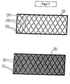
- reference numeral 10 denotes a central ply whose surface facing the viewer has a honeycomb-shaped structure formed by a network of linear recesses 14 of finite length extending throughout the entire surface.
- air channels or flow channels are formed in two directions x and y.
- the depressions may be related to FIG. 1 be explained explained.
- most of the surface is planar (see hexagons 15) and can come into direct contact with a capping layer.
- a large contact surface is formed, which favors the strength of an adhesive connection and the mechanical strength of a cover layer.
- the hot stamping is followed by covering the middle layer with textile glass and possibly additional components such as a frame, wood inserts and expanded metals. These elements correspond to the upper cover layer.
- the textile glass used in steps (a) and (b) is a standardized and inexpensive product.
- the selection of special textile glasses is application-specific.
- textile glasses with continuous fibers can be laid without overlaps such as endless covers, fabrics and rovings according to the lines of force.
- scrims with isotropic fiber orientation such as cut mats or scrims, or cover layers produced using LFI processes may be applied.
- the resin used in step (c) is a foamable PU system.
- the resin application is carried out by spraying using the Airless spray technique.
- the guidance of the spray head takes place in the x and y directions on preferably linear paths.
- the hardening process is associated with a muted reaction so that the foam core is not thermally damaged.
- the resin system has a starting time of between 1 and 5 minutes and a rise time of between 5 and 10 minutes.
- Step (f) comprises a pressing time of between 10 and 30 minutes at a pressing temperature of between 60 and 80 ° C.
- the calender has tempered rollers.
- an IR radiator is used for heating the plates.
- the plates are fed to the hot stamping machine and the structure is stamped by the calendering roll.
- the thickness of the middle layer after the hot stamping is defined, whereby in this step also the thickness calibration of the middle layer takes place.
- a fiberglass endless mat and several wood inlays are placed on the textured center panel and a spray table.
- a foamable 2-component PU system is provided in a high-pressure mixing plant and dispensed onto the spray table and center plate with an airless spray system.
- the 2K PU system has a starting time of about 3 minutes and a climb time of about 8 minutes.
- the spray head can be positioned at several points in the y-direction and at two points in the z-direction, the two points in the z-direction corresponding to the positions for spraying the lower cover layer and the upper cover layer. In the x-direction, a fast linear movement takes place at a speed of about 1.5 m / s with rapid acceleration.
- the control of the movement and the switching on and off of the mixing head is done automatically and coordinate controlled.
- the spraying is followed by a point extraction on the resin application.
- the manufacturing device further comprises unwinding devices for cover layers, with the help of a bottom heating plate and a PVC coating on one side of the not cured topcoat are applied.
- the PVC coating has no or a coordinated foam backing, so that its back-side structure adheres adhesively and mechanically to the cover layer during curing of the 2-component PU system. Due to the mechanical entanglement, the adhesion is independent of any surface-active additives from the PVC production.
- the pressing time is about 20 minutes at a temperature of about 60 ° C.
- the 2-component PU system cures to a hard-elastic hard foam with a bulk density of about 150 kg / m 3 to 1000 kg / m 3 and a homogeneous, closed cell structure.
- the weight fraction of glass fibers in the total weight of the cover layer is about 30% to 50%.
- the resulting bottom plate has load-resistant properties under fatigue loading.
- An endurance test in the laboratory with 150 kg load and 200,000 cycles shows excellent durability.
Landscapes
- Engineering & Computer Science (AREA)
- Mechanical Engineering (AREA)
- Architecture (AREA)
- Civil Engineering (AREA)
- Structural Engineering (AREA)
- Chemical & Material Sciences (AREA)
- Composite Materials (AREA)
- Laminated Bodies (AREA)
- Casting Or Compression Moulding Of Plastics Or The Like (AREA)
Description
- Die Erfindung betrifft ein Verfahren zur Herstellung eines Flächenbauteils.
- Gattungsgemäße Verfahren sind aus dem Stand der Technik bekannt. Beispielsweise offenbart die
US 2003/0168763 A1 ein Verfahren zur Herstellung einer geschäumten Kunststoffplatte aus einem plattenförmigen Rohling aus einem schäumbaren Kunststoffmaterial. - Der Einsatz von Flächenbauteilen in Wohnwägen oder Wohnmobilen, beispielsweise als Bodenplatte, als Seitenteil, oder als Bestandteil von Einrichtungsgegenständen ist bekannt.
- Dabei sind gewisse Anforderungen an die mechanischen Eigenschaften und die Bearbeitbarkeit der Flächenbauteile gestellt. Beispielweise sollen die Flächenbauteile eine gewisse Stabilität, Haltbarkeit, mechanische Dauerbelastbarkeit, Temperaturbeständigkeit im Anwendungsbereich, und Witterungs- und Korrosionsbeständigkeit aufweisen. Ferner sollen die Flächenbauteile beispielsweise für die Bearbeitung mittels Fräsen, Bohren, Schneiden, und diversen Fügetechniken zugänglich sein. Vorteilhaft ist es, wenn die Flächenbauteile am Band herstellbar sind.
- Letztlich spielen auch optische Eigenschaften wie die Oberflächengüte, die Farbgebung oder die Dekor- und Designfreiheit, und die Nachhaltigkeit, zum Beispiel die Recyclingfähigkeit und die dauerhafte Verfügbarkeit der Ausgangsmaterialien eine Rolle.
- Eine Aufgabe der Erfindung ist es, ein Verfahren zur Herstellung gattungsgemäßer Flächenbauteile mit einem geringeren Gewicht bereitzustellen, wobei die Herstellungskosten vorzugsweise stabil bleiben und insbesondere gesenkt werden, und die obengenannten Rahmenbedingungen vorzugsweise hinreichend eingehalten und insbesondere verbessert werden.
- Diese Aufgabe wird erfindungsgemäß mit einem Verfahren gemäß Anspruch 1 gelöst. Vorteilhafte Ausgestaltungen ergeben sich aus den Unteransprüchen.
- Mit einem erfindungsgemäßen Verfahren ist ein Flächenbauteil herstellbar, welches wenigstens abschnittsweise wenigstens drei sandwichartig geschichtete Lagen aufweist. Dabei soll eine Mittelage beidseitig von einer Deckschicht bedeckt sein. Wenigstens eine und vorzugsweise beide Oberflächen der Mittelage weisen wenigstens abschnittsweise eine Oberflächenstruktur auf.
- Unter einem Flächenbauteil wird im Rahmen der Erfindung beispielsweise eine Platte, beziehungsweise ein ebenes, flächiges Bauteil aus einem vorzugsweise steifen Material verstanden.
- In einer Ausführungsform handelt es sich um eine wenigstens dreischichtige Sandwichplatte, vorzugsweise um eine Sandwichhybridplatte. Unter einer Sandwichhybridplatte ist im Rahmen der Erfindung eine wenigstens dreischichtige Sandwichplatte zu verstehen, deren Mittelschicht sich wenigstens in der Materialwahl und vorzugsweise zusätzlich in der Stärke und Struktur von den Deckschichten unterscheidet.
- In einer Ausführungsform deckt sich der Bereich der Mittelschicht, der eine Oberflächenstruktur aufweist mit dem Bereich der Mitteschicht, welcher auf der jeweiligen Seite mit einer Deckschicht überzogen ist.
- In einer Ausführungsform erstrecken sich alle Lagen des Flächenbauteils und/oder die Oberflächenstruktur der Mittellage über das gesamte Flächenbauteil.
- In einer Ausführungsform beträgt die Gesamtstärke des Flächenbauteils zwischen etwa 10 und etwa 100 mm, vorzugsweise zwischen etwa 30 und etwa 60 mm.
- In einer Ausführungsform weist die Oberflächenstruktur ein vorzugsweise flächendeckend verbundenes Netz an Vertiefungen, beispielsweise Rillen beziehungsweise Kanäle auf, oder besteht daraus. Dies steht im Gegensatz zu erhabenen Strukturen, wie Rippen und dergleichen. In einer Ausführungsform ist die strukturierte Oberfläche zu mindestens 60% und vorzugsweise zu mindestens 70% eine planare Fläche, die Vertiefungen aufweist, die weniger als 40% und vorzugsweise weniger als 30% der planaren Oberfläche einnehmen.
- In einer Ausführungsform weist die Oberflächenstruktur eine zweidimensionale Struktur aus sich kreuzenden beziehungsweise überkreuzenden Vertiefungen, beispielsweise Rillen beziehungsweise Kanäle auf, oder besteht daraus. Die Rillen können gerade oder geschwungen sein und/oder sich senkrecht oder schräg kreuzen. Die Rillen können Richtungsanteile in x- und y- Richtung der Oberfläche des Mittelteils aufweisen. Beispielsweise können senkrechte Vertiefungen ein quadratisches, rechteckiges, rhomboedrisches, wabenartiges, oder ähnliches Muster ausbilden.
- Die Vertiefungen können in einer Ausführungsform einen eckigen (beispielsweise dreieckigen) oder runden (beispielsweise halbkreisförmigen) Querschnitt aufweisen. Sie können in einer Ausführungsform zwischen etwa 0,5 und etwa 5 mm, vorzugsweise zwischen etwa 1 und etwa 2 mm tief sein.
- In einer Ausführungsform ist die Struktur über den gesamten strukturierten Bereich gleichmäßig ausgeführt. In einer anderen Ausführungsform ist die Oberflächenstruktur über den strukturierten Bereich inhomogen ausgebildet.
- Die Struktur ermöglicht es, ein vergleichsweise billiges Standardmaterial mit vorzugsweise geringer Dichte als Mittellage einzusetzen, und dennoch vorteilhafte Eigenschaften im Endprodukt zu erzielen. Daraus kann sich ein strategischer Kostenvorteil ergeben.
- In einer Ausführungsform kann die Mittellage durch deren Strukturierung nicht nur die klassischen Aufgaben einer Sandwichmittellage wie Isolation oder SchubDruck-Übertragung zwischen den zugfesten Deckschichten übernehmen, sondern auch ein oder mehrere weitere Funktionen.
- Beispielsweise kann die Strukturierung eine Voraussetzung für das Aushärten eines aushärtbaren Matrixmaterials einer Deckschicht wie z.B. ein getriebenes Schaumsystem direkt an der Mittellage sein, da die Struktur für eine stabile Entlüftung von Luft oder auch Treibmitteln beim Aushärten sorgen kann. So kann die Strukturierung die Durchführung eines ordinären und einstufigen Chargenpressganges ermöglichen, da keine Entlüftungsschritte notwendig werden. Es kann ein größerer Spielraum bei der Wahl der Deckschicht und der Beschichtungsmethode eingeräumt werden.
- Alternativ oder zusätzlich kann die Strukturierung die Haftung der Deckschicht begünstigen und/oder die mechanischen Eigenschaften der Decklage beeinflussen. Durch die größtenteils ebene Oberfläche wird trotz der Fähigkeit zum Entlüften von Luft oder auch Treibmitteln eine große Auflagefläche für die Deckschicht erreicht, was die Trittfestigkeit begünstigt und einem Verbeulen beziehungsweise Brechen der Deckschichte entgegentritt.
- Alternativ oder zusätzlich kann die Strukturierung eine Verteilung von die Struktur aufgetragenem Matrixmaterial über die Oberfläche begünstigen, indem das Harz in die Vertiefungen eindringt, und/oder für eine Verteilung des Harzes und zum Ausgleich von Unstetigkeiten in der Stärke der Mittelschicht sorgen. Die Vertiefungen können als Fließkanäle dienen.
- In einer Ausführungsform kann die Strukturierung der Mittellage gezielt dazu eingesetzt werden, Beispielsweise können je nach Struktur Verrippungen und/oder systematische Anschraubpunkte kreiert werden. Beispielsweise kann eine Gitterstruktur bei der Beanspruchung des fertigen Flächenbauteils diesem eine zusätzliche Festigkeit verleihen.
- Die strukturierte Mittellage kann dabei als eine verlorene Form, eine formgebende Mittellage betrachtet werden.
- In einer Ausführungsform können in die Vertiefungen zusätzlich Strukturelemente wie beispielsweise Gitterroste und dergleichen eingebracht sein. Dies kann die Festigkeit des Flächenbauteils begünstigen.
- Die Mittellage ist aus einem Polymerschaum gefertigt, vorzugsweise einem Polymerschaum auf Polystyrolbasis. Solche Werkstoffe haben typischerweise den Vorteil eines niedrigen Raumgewichtes und einer guten Isolationswirkung.
- Als Polymerschaum eignen sich vorzugsweise hartelastische und/oder thermoplastische oder duroplastische Polymerschäume, insbesondere Hartschäume. Beispiele umfassen Polymerschäume aufweisend oder bestehend aus Polystyrol (PS), Polyvinylchlorid (PVC), Polyethylenterephtalat (PET) und Polyuretan (PUR). Besonders bevorzugt sind Kunststoffschäume auf PS-Basis, wie beispielsweise XPS (Styrodur) oder EPS (Styropor). Bei den eingesetzten Polymerschäumen handelt es sich um standardisierte Isolationsware. Da letztere typischerweise billig und am Markt frei verfügbar ist, kann sich durch deren Veredelung (Strukturierung) ein strategischer Kostenvorteil ergeben.
- Die Mittellage ist starr.
- In einer Ausführungsform ist das Flächenbauteil eine Sandwichplatte mit einem Waben- oder Schaumkern.
- Das Raumgewicht der Mittellage kann in einer Ausführungsform zwischen etwa 30 und etwa 70 kg/m3 betragen. Die Stärke der Mittellage kann in einer Ausführungsform zwischen etwa 10 und etwa 70mm, vorzugsweise zwischen etwa 30 und etwa 55 mm betragen.
- In einer Ausführungsform bestehen eine und vorzugsweise beide Deckschichten aus einem faserverstärkten Werkstoff, vorzugsweise aus einem faserverstärkten Kunststoff. Der faserverstärkte Werkstoff kann auch als Faserverbundwerkstoff oder als faserverstärktes Composit bezeichnet werden.
- In einer Ausführungsform umfasst die Faserverstärkung eine Glasfaserverstärkung und/oder eine Carbonfaserverstärkung und/oder eine Aramidfaserverstärkung oder besteht daraus. Hybridfaserverstärkungen umfassen wenigstens zwei Fasern vorzugsweise ausgewählt aus der Gruppe Glasfaser, Carbonfaser und Aramidfaser sind ebenfalls umfasst. Besonders bevorzugt ist der Einsatz einer Glasfaserverstärkung beziehungsweise der Einsatz von Textilglas als Faserverstärkung.
- In einer Ausführungsform besteht eine und vorzugsweise beide Deckschichten aus einem glasfaserverstärkten Kunststoff (GFK).
- In einer Ausführungsform macht die Faserverstärkung der Deckschichten zwischen etwa 5 Gew.-% und etwa 50 Gew.-%, und vorzugsweise zwischen etwa 20 Gew.-% und etwa 40 Gew.-% des Gesamtgewichts der Deckschichten aus.
- Geeignete Faserstrukturen der Faserverstärkung umfassen eindimensionale oder zweidimensionale Strukturen. Diese können in der Ebene des Flächenbauteils gerichtete oder isotrop ausgerichtete Fasern oder Faserverbände aufweisen. Geeignete eindimensionale Strukturen umfassen unidirektionale Gelege aus Rovings oder Bändern. Geeignete zweidimensionale Strukturen umfassen textile Strukturen aus Rovings oder Bändern, wie beispielsweise Gelege, Vliese, Gestricke, Matten (Schnittmatten, Endlosmatten) oder Gewebe. Geeignete Gewebe bestehen gegebenenfalls aus ortogonalen Fadensystemen. Geeignete Gelege können mehrere Faserlagen umfassen, die in verschiedene Richtungen aufeinander abgelegt und mit denen Haltefäden in Z-Richtung miteinander vernäht sind. Geeignete Gewebe umfassen Leinwandgewebe, Köpergewebe oder Atlasgewebe. Diffuse Faserverstärkungen können beispielsweise mit Hilfe des Langfaserinjektionsverfahrens (LFI) hergestellt werden.
- Die Art dieser Decklage stellt in einer Ausführungsform ein wichtiges Element dar. Mögliche Funktionen der so ausgebildeten Decklage umfassen die Verklebung mit der Mittellage ohne zusätzlichen Klebstoff, die Verklebung beziehungsweise Verankerung mit gegebenenfalls in die Decklage eingefassten oder auf die Decklage aufgelegten Zusatzbauteilen ohne zusätzlichen Klebstoff, und/oder den Ausgleich von Dickentoleranzen der Mittellage.
- Zwei auf unterschiedlichen Seiten der Mittellage befindliche Decklagen des Sandwichbauteils können in einer Ausführungsform eine unterschiedliche Stärke aufweisen und/oder aus unterschiedlichen Materialien gefertigt sein. Beispielsweise kann eine Decklage aus einem faserverstärkten Kunststoff, und die andere Decklage aus einem nicht faserverstärkten Kunststoff gefertigt sein. Eine Decklage kann beispielsweise nur eine Dekorlage darstellen.
- In einer Ausführungsform umfasst das Matrixmaterial des faserverstärkten Werkstoffes einen vorzugsweise starren Polymerschaum, insbesondere einen härteelastischen Hartschaum, oder besteht daraus. Das Matrixmaterial kann eine zellige Struktur, beispielsweise eine offenzellige, gemischtzellige oder geschlossenzellige Struktur, vorzugsweise eine homogene und geschlossenzellige Struktur aufweisen. Geeignete Polymerschäume umfassen insbesondere duroplastische Polymerschäume aus Polyurethan, Polyepoxid oder Polyester. Besonders bevorzugt ist ein Polymerschaum auf Polyurethanbasis. In einer Ausführungsform weist das Matrixmaterial ein Raumgewicht von zwischen etwa 100 und etwa 1000 kg/m3, vorzugsweise von zwischen etwa 120 und etwa 300 kg/m3 auf.
- In einer Ausführungsform umfasst das Flächenbauteil ferner Zusatzbauteile, welche in die Deckschicht eingefasst sind und/oder adhäsiv und/oder mechanisch darauf verklebt und/oder verkeilt sind. Geeignete Zusatzbauteile umfassen beispielsweise Rahmen, Holzeinleger oder Streckmetalle. Weitere geeignete Zusatzbauteile umfassen Dekorelemente und Überzüge wie eine Bodenheizungsfolie, ein PVC-Belag oder Dekorfolien. Andere geeignete Zusatzbauteile umfassen Bauelemente oder Verbindungselemente wie beispielsweise Schienen, Muttern oder Nippel.
- In einer Ausführungsform handelt es sich bei den Flächenbauteilen um ein Bauteil für einen Caravan, beziehungsweise einen Wohnwagen und/oder ein Wohnmobil. Denkbar ist dabei der Einsatz als Bodenplatte, als Wandungsplatte beziehungsweise Seitenteil, oder auch als Bestandteil eines Einrichtungsgegenstandes. Besonders bevorzugt ist der Einsatz als Bodenplatte. Durch den Einsatz eines derartigen Bauteils können in einer Ausführungsform eine signifikante Gewichtsreduktion des Caravans und/oder ein strategischer Kostenvorteil erreicht werden.
- Erfindungsgemäß ist ein Verfahren zur Herstellung eines Flächenbauteils vorgesehen, welches die folgenden Schritte umfasst:
- a) das Bereitstellen einer aus einem Polymerschaum bestehenden und starren Mittellage;
- b) wenigstens abschnittsweises Strukturieren wenigstens einer und vorzugsweise beider Oberflächen der Mittellage;
- c) Auftragen eines faserverstärkten Werkstoffes auf die strukturierte Mittellage und/oder Unterlegen der strukturierten Mittellage mit einem faserverstärkten Werkstoff; und
- d) Verbinden der Mittellage mit dem faserverstärkten Werkstoff und/oder Aushärten des faserverstärkten Werkstoffes.
- Die Reihenfolge der Schritte (a) bis (d) ist notwendigerweise bis zu dem Grad einzuhalten, dass der faserverstärkte Werkstoff auf die strukturierte Oberfläche aufgetragen wird. Es ist jedoch denkbar und von der Erfindung umfasst, dass zwei Abfolgen (b)→(c)→(d) - je eine Abfolge für jede Deckschicht - hintereinandergeschaltet werden. Ebenso ist eine Abfolge (b)→(c)→(d)→(c)→(d) denkbar. Dies entspricht einem abwechselnden Auftragen beziehungsweise Unterlegen der Mittellage mit dem faserverstärkten Werkstoff. Was die übrigen Schritte betrifft, ist, abgesehen von der genannten Reihenfolge, jede denkbare Reihenfolge von der Erfindung umfasst.
- In einer Ausführungsform umfasst das Strukturieren gemäß Schritt (b) das Heißprägen wenigstens einer und vorzugsweise beider Oberflächen der Mittellage. Alternativ oder zusätzlich kann das Strukturieren Fräsen und/oder Schneiden einer Struktur in die Oberfläche umfassen. Die Strukturierung beider Oberflächen kann gleichzeitig oder sequentiell erfolgen. Besonders bevorzugt ist das Heißprägen mit Hilfe eines Kalanders.
- In einer Ausführungsform umfasst das Strukturieren gemäß Schritt (b) die Fertigung einer Oberflächenstruktur wie sie im Zusammenhang mit der Diskussion des Flächenbauteils beschrieben wurde.
- In einer Ausführungsform umfasst das Auftragen eines faserverstärkten Werkstoffes auf die strukturierte Mittellage gemäß Schritt (c) das Auflegen eines textilen Faserhalbzeugs auf die strukturierte Mittellage und dessen Imprägnieren mit einem aushärtbaren Matrixmaterial.
- In einer Ausführungsform umfasst das Unterlegen der strukturierten Mittellage mit einem faserverstärktem Werkstoff gemäß Schritt (c) das Auflegen eines textilen Faserhalbzeugs auf eine Unterlage, dessen Imprägnieren mit einem aushärtbaren Matrixmaterial, und das anschließende Auflegen der strukturierten Mittellage. Die Unterlage gehört dabei nicht zum Flächenbauteil. Es kann sich beispielsweise um einen Sprühtisch oder dergleichen handeln.
- In einer Ausführungsform umfasst das Unterlegen und/oder Auftragen gemäß Schritt (c) das Auflegen und/oder Unterlegen eines vorimprägnierten Faserhalbzeugs, wie beispielsweise eines Prepregs.
- In einer Ausführungsform umfasst Schritt (c) das Auftragen von aushärtbarem Matrixmaterial auf die Unterlage oder Mittellage vor Auflegen des textilen und gegebenenfalls vorimprägnierten Faserhalbzeugs.
- In einer Ausführungsform umfasst Schritt (c) das Besprühen der Mittellage im Härtespritzverfahren, insbesondere im Langfaserinjektionsverfahren. Dabei kann über einen Spritzkopf aushärtbares Matrixmaterial mit darin dispergierten, zerschnittenen Verstärkungsfasern aufgetragen werden. Gegebenenfalls kann die so aufgetragene Lage vor dem Aushärten separat verdichtet und entlüftet werden.
- Geeignete textile Faserhalbzeuge umfassen Glasfaserhalbzeuge, Carbonfaserhalbzeuge, Aramidfaserhalbzeuge oder Hybridfaserhalbzeuge umfassend wenigstens zwei Fasern, vorzugsweise ausgewählt aus der Gruppe Glasfaser, Carbonfaser und Aramidfaser. Bevorzugt sind Glasfaserhalbzeuge wie Textilglas.
- Geeignete Halbzeuge umfassen eindimensionale oder zweidimensionale Halbzeuge. Diese können in der Ebene des Flächenbauteils gerichtete oder isotrop ausgerichtete Fasern oder Faserverbände aufweisen. Geeignete eindimensionale Halbzeuge umfassen unidirektionale Gelege aus Rovings oder Bändern. Geeignete zweidimensionale Halbzeuge umfassen textile Strukturen aus Rovings oder Bändern, wie beispielsweise Gelege, Vliese, Gestricke, Matten (Schnittmatten, Endlosmatten) oder Gewebe. Geeignete Gewebe bestehen gegebenenfalls aus ortogonalen Fadensystemen. Geeignete Gelege können mehrere Faserlagen umfassen, die in verschiedene Richtungen aufeinander abgelegt und mit denen Haltefäden in Z-Richtung miteinander vernäht sind. Geeignete Gewebe umfassen Leinwandgewebe, Köpergewebe oder Atlasgewebe.
- In einer Ausführungsform umfasst das aushärtbare Matrixmaterial ein aushärtendes und/oder schäumendes Polymersystem beziehungsweise Harz, oder besteht daraus. Geeignete aushärtbare Polymersysteme umfassen Einkomponentensysteme, Zweikomponentensysteme oder Mehrkomponentensysteme. Polyurethansysteme, Epoxidsysteme oder Polyestersysteme sind geeignet. In einer Ausführungsform handelt es sich um ein härtendes, ungesättigtes Polyesterharz. Bevorzugt ist ein Zweikomponenten (2-K) Polyurethansystem. Polymersysteme, welche zu duroplastischen Kunststoffen, vorzugsweise zu einem ausgehärteten Matrixmaterial des faserverstärkten Werkstoffes, wie dieser im Zusammenhang mit dem Flächenbauteil diskutiert wurde, aushärten, sind besonders bevorzugt.
- Sollte es sich um ein Mehrkomponentensystem handeln, so kann die vorgelagerte, das heißt vor der Imprägnierung der Faserhalbzeuge durchzuführende Durchmischung der einzelnen Komponenten in einer Hochdruckmischanlage erfolgen.
- Geeignete Imprägnierungsverfahren für das Faserhalbzeug umfassen das Autoklavieren, das Spritzgießen, das Laminieren, das Filmbeschichten, das Harzinjizieren, das Besprühen, und dergleichen. Besonders bevorzugt ist das Besprühen des aufgelegten, trockenen oder vorimprägnierten Faserhalbzeuges. Das Besprühen kann in einer Ausführungsform durch Führung eines Sprühkopfes in der Ebene (in x- und y-Richtung) der Mittellage beziehungsweise der Flächenbauteile geführt werden. Beispielsweise umfasst die Bewegung des Sprühkopfes eine Linearbewegung mit Überführungsgeschwindigkeiten von zwischen etwa 1 und etwa 2 m/s. In einer Ausführungsform werden ein, zwei oder weniger als fünf Besprühungsvorgänge zum Imprägnieren der Halbzeuge verwendet.
- In einer Ausführungsform umfasst das Verbinden und Aushärten gemäß Schritt (d) ein adhäsives Verbinden der entstehenden beziehungsweise aushärtenden Deckschicht mit der Mittellage. So kann eine Verbindung zwischen Deckschicht und Mittellage allein durch das Aushärten der Matrix erfolgen.
- In einer Ausführungsform umfasst das Verbinden und Aushärten gemäß Schritt (d) das Verpressen des vorzugsweise noch nicht ausgehärteten faserverstärkten Werkstoffs mit der Mittellage. Geeignete Presszeiten umfassen beispielsweise zwischen etwa 10 und etwa 30 Minuten, vorzugsweise zwischen etwa 15 und etwa 25 Minuten. Geeignete Presstemperaturen umfassen beispielsweise den Bereich von zwischen etwa 40°C und etwa 100°C, vorzugsweise zwischen etwa 50°C und etwa 80°C.
- In einer Ausführungsform können Schritte (c) und (d) einander entsprechen oder nahtlos ineinander übergehen, da bei einem Auftragen eines aushärtbaren Matrixmaterials die Verbindung bereits einsetzt eine keine klare Grenze gezogen werden kann.
- Wenn ein schäumendes Polymermaterial als aushärtbares Matrixmaterial verwendet wird, kann dieses Material eine Startzeit von beispielsweise zwischen etwa 30 Sekunden und etwa 5 Minuten, vorzugsweise zwischen etwa 2 Minuten und etwa 4 Minuten aufweisen. Ferner kann es eine offene Zeit beziehungsweise Steigzeit von zwischen etwa 2 Minuten und etwa 15 Minuten, vorzugsweise von zwischen etwa 5 und etwa 10 Minuten aufweisen. Die Zeiten sind letztendlich auf den Fertigungsprozess abzustimmen.
- In einer Ausführungsform umfasst das Verfahren ferner das Belegen der Mittelschicht mit Zusatzbauteil und/oder das Einfassen von Zusatzbauteilen in den nicht ausgehärteten faserverstärkten Werkstoff und/oder das Auflegen von Zusatzbauteilen auf den nicht ausgehärteten faserverstärkten Werkstoff. Geeignete Zusatzbauteile wurden in Zusammenhang mit dem Flächenbauteil diskutiert. Durch das Aushärten beziehungsweise Pressen des faserverstärkten Werkstoffes können die so an das Flächenbauteil beziehungsweise dessen Rohling assoziierten Zusatzbauteile in einer Ausführungsform irreversibel in die Deckschicht einfasst und/oder adhäsiv und/oder mechanisch darauf beziehungsweise darin verklebt werden.
- Erfindungsgemäß hergestellte Flächenbauteile können in einem Caravan, beziehungsweise Wohnwagen oder Wohnmobil eingesetzt werden, vorzugsweise als Bodenplatte, als Wandungsplatte beziehungsweise Seitenteil, oder als Bestandteil eines Einrichtungsgegenstandes.
- Weitere Einzelheiten und Vorteile der Erfindung ergeben sich aus den nachfolgend beschriebenen Figuren und Ausführungsbeispielen. In den Figuren zeigen:
- Figur 1:
- die Oberflächenstruktur der Mittellage einer Ausführungsform eines mittels eines erfindungsgemäßen Verfahrens hergestellten Flächenbauteils, und
- Figur 2:
- die Oberflächenstruktur der Mittellage einer anderen Ausführungsform eines mittels eines erfindungsgemäßen Verfahrens hergestellten Flächenbauteils.
- Dieses Beispiel beschreibt die Herstellung einer Sandwichhybridplatte in einem Pressenzyklus, wobei feste Faserverbunddecklagen entstehen, in die gegebenenfalls auch Strukturteile, Verbindungselemente und Dekordecklagen mit eingeklebt werden können. Das Verfahren ermöglicht eine integrierte Herstellung einer GFK-Platte im Zuge der Herstellung einer Sandwichplatte, was durch eine spezielle Strukturierung der Mittellage ermöglicht wird. Der Herstellungsprozess umfasst die folgenden Schritte in gegebener Abfolge:
- a) Vorfertigung der Mittellage durch Strukturieren der Mittellage und Auflegen von Textilglas und gegebenenfalls Zusatzbauteilen einer oberen Decklage;
- b) Auflegen von Textilglas und gegebenenfalls Zusatzbauteilen einer unteren Decklage auf einem Sprühtisch;
- c) Harzauftrag auf die untere Decklage;
- d) Auflegen der vorgefertigten Mittellage;
- e) Harzauftrag auf die obere Decklage;
- f) gegebenenfalls, Auflegen von weiteren Schichten wie einer Bodenheizungsfolie oder Überzügen wie einem PVC-Belag; und
- g) Pressen.
- Schritte (c) bis (g) umfassen den eigentlichen Pressprozess. Deren Ablauf ist miteinander verkettet beziehungsweise durch die Steigzeit und Presszeit bestimmt.
- Abschließend kann ein Entformen und/oder ein mehrseitiger Beschnitt und/oder ein Fräsen erfolgen.
- Schritt (a) des Vorfertigens der Mittellage umfasst das Bereitstellen einer kostengünstigen PS-Polymerschaumplatte (Isolationsware) mit zwischen 10 und 100 mm Stärke und zwischen 30 bis 70 kg/m3 Raumgewicht.
- Diese Mittellage wird in einem Kalender beidseitig heißgeprägt und so mit einer Oberflächenstruktur versehen. Mögliche Oberflächenstrukturen sind in
Figuren 1 und2 gezeigt. - In
Figur 1 ist mit Bezugszeichen 10 die Mittellage gekennzeichnet, und mit Bezugszeichen 20 eine korrespondierende Decklage. - Die Mittellage 10 weist auf der dem Betrachter zugewandten Oberfläche eine rautenförmige Struktur auf, die aus parallelen Gruppen 11 und 12 von linearen Vertiefungen gebildet ist. Die linearen Vertiefungen der unterschiedlichen Gruppen 11 beziehungsweise 12 stehen gewinkelt aufeinander und erstrecken sich durchgehend über die gesamte Oberfläche, sodass durchgehende Luftkanäle beziehungsweise Fließkanäle in zwei Richtungen x und y gebildet werden. Die Vertiefungen sind im Querschnitt rechtwinklig und weisen eine Tiefe von beispielsweise zwischen etwa 1 und etwa 2 mm sowie eine Breite von beispielsweise zwischen etwa 0,5 und etwa 1 mm auf. Die Rauten haben Abmessungen von beispielsweise etwa 15 mm von Spitze zu Spitze auf der längeren Achse und etwa 6 bis etwa 7 mm von Spitze zu Spitze auf der kürzeren Achse.
- Der Großteil der Oberfläche ist jedoch planar (siehe Rauten 13) und kann in direkten Kontakt mit einer Deckschicht treten. So wird eine große Auflagefläche gebildet, welche die Stärke einer adhäsiven Verbindung und die mechanische Belastbarkeit einer Deckschicht begünstigt.
- Die Decklage 20 weist das Abbild der Oberfläche der Mittellage auf, in diesem Fall eine rautenförmige Struktur aus erhabenen Stegen 21 und 22.
- In
Figur 2 ist mit Bezugszeichen 10 eine Mittellage gekennzeichnet, deren dem Betrachter zugewandte Oberfläche eine wabenförmige Struktur aufweist, die von einem sich durchgehend über die gesamte Oberfläche erstreckenden Netzwerk aus linearen Vertiefungen 14 mit endlicher Länge gebildet wird. So werden Luftkanäle beziehungsweise Fließkanäle in zwei Richtungen x und y gebildet. Die Vertiefungen können wie im Zusammenhang mitFigur 1 erläutert ausgebildet sein. - Wie in der Struktur gemäß
Figur 1 ist der Großteil der Oberfläche planar (siehe Sechsecke 15) und kann in direkten Kontakt mit einer Deckschicht treten. So wird eine große Auflagefläche gebildet, welche die Stärke einer adhäsiven Verbindung und die mechanische Belastbarkeit einer Deckschicht begünstigt. - Auf das Heißprägen folgt ein Belegen der Mittellage mit Textilglas und gegebenenfalls Zusatzbauteilen wie einem Rahmen, Holzeinlegern und Streckmetallen. Diese Elemente entsprechen der oberen Decklage.
- Bei dem in Schritten (a) und (b) verwendeten Textilglas handelt es sich um ein standardisiertes und kostengünstiges Produkt. Die Auswahl spezieller Textilgläser erfolgt anwendungsspezifisch. Beispielsweise können Textilgläser mit durchgehenden Fasern ohne Überlappungen wie Endlosgelege, Gewebe und Rovings gemäß den Kraftlinien verlegt werden. Alternativ oder zusätzlich können Gelege mit isotroper Faserausrichtung wie Schnittmatten oder Gelege, beziehungsweise mit LFI-Verfahren hergestellte Deckschichten aufgetragen werden.
- Das in Schritt (c) eingesetzte Harz ist ein schäumbares PU-System. Die Harzauftragung erfolgt durch Besprühen mit Hilfe der Airless-Sprühtechnik. Die Führung des Sprühkopfes erfolgt in x- und y-Richtung auf vorzugsweise linearen Bahnen. Der Härtungsprozess ist mit einer gedämpften Reaktion verbunden, sodass der Schaumkern nicht thermisch geschädigt wird. Das Harzsystem hat eine Startzeit von zwischen 1 und 5 Minuten und eine Steigzeit von zwischen 5 und 10 Minuten.
- Schritt (f) umfasst eine Presszeit von zwischen 10 und 30 Minuten bei einer Presstemperatur von zwischen 60 und 80°C.
- Eine konkrete Parametrisierung des in Beispiel 1 beschriebenen Herstellungsprozesseses zur Herstellung einer Bodenplatte für einen Caravan ist im Folgenden beschrieben:
- Eine kostengünstige XPS-Dämmplatte mit einem Raumgewicht von etwa 50 kg/m3 und 50 mm Stärke wird bereitgestellt. Es folgt die Behandlung in einem Verfahren mit Schritten (a) bis (g) gemäß Beispiel 1.
- Dies umfasst eine beidseitige Strukturierung (Heißprägung) die mittels Kalander hergestellt wurde. Der Kalander weist temperierte Walzen auf. Für ein Erhitzen der Platten wird ein IR-Strahler verwendet. Die Platten werden der Heißprägeapparatur zugeführt und die Struktur wird durch die Kalanderwalze geprägt. Die Stärke der Mittelschicht nach der Heißprägung ist definiert, wodurch in diesem Arbeitsschritt auch die Dickenkalibrierung der Mittellage erfolgt.
- Eine Glasfaserendlosmatte sowie mehrere Holzeinleger werden auf die strukturierte Mittelplatte und einen Sprühtisch gelegt.
- Ein schäumbares 2-K PU-System wird in einer Hochdruckmischanlage bereitgestellt und mit einer Airless-Sprühanlage Dosiereinlage auf den Sprühtisch und die Mittelplatte abgegeben. Das 2-K PU-System hat eine Startzeit von etwa 3 Minuten und eine Steigzeit von etwa 8 Minuten. Der Sprühkopf ist y-Richtung an mehreren Punkten und in z-Richtung an zwei Punkten positionierfähig, wobei die zwei Punkte in z-Richtung den Positionen für die Besprühung der unteren Decklage und der oberen Decklage entsprachen. In x-Richtung erfolgt eine schnelle Linearbewegung mit einer Geschwindigkeit von etwa 1,5 m/s bei schneller Beschleunigung. Die Steuerung der Bewegung sowie die An- und Abschaltung des Mischkopfes erfolgt automatisch und koordinatengesteuert. Auf das Besprühen folgt eine Punktabsaugung am Harzauftrag.
- Die Fertigungsvorrichtung umfasst ferner Abrollvorrichtungen für Deckschichten, mit deren Hilfe eine Bodenheizungsplatte und ein PVC-Belag einseitig auf die nicht ausgehärtete Deckschicht aufgelegt werden. Der PVC-Belag weist keinen oder einen abgestimmten Schaumrücken auf, sodass dessen rückseitige Struktur beim Aushärten des 2-K PU-Systems adhäsiv und mechanisch mit der Deckschicht verklebt. Durch die mechanische Verkrallung ist die Haftung unabhängig von etwaigen oberflächenwirksamen Zusatzstoffen aus der PVC-Herstellung.
- Die Presszeit beträgt etwa 20 Minuten bei einer Temperatur von etwa 60°C.
- Das 2-K PU-System härtet zu einem hartelastischen Hartschaum mit einer Raumdichte von etwa 150 kg/m3 bis 1000 kg/m3 und einer homogenen, geschlossenen Zellstruktur aus. Der Gewichtsanteil an Glasfasern am Gesamtgewicht der Deckschicht beträgt etwa 30% bis 50%.
- Die resultierende Bodenplatte hat belastungsresistente Eigenschaften bei Dauerschwingbelastungen. Bei einem Dauerversuch im Labor mit 150 kg Belastung und 200.000 Zyklen zeigt sich eine hervorragende Beständigkeit.
- Zusammenfassend ergibt sich, dass durch ein erfindungsgemäßes Herstellungsverfahren eine hohe Wirtschaftlichkeit bei gleichzeitiger Gewichtsreduktion und Erfüllung der weiteren Anforderungen an gattungsgemäße Bauteile durch die Nutzung von Synergien erreicht werden kann. Diese umfassen insbesondere die Veredelung durch Strukturierung von kostengünstigen Mittelschichten, die Auswahl des richtigen Matrixwerkstoffes für die Deckschichten und den Einsatz der richtigen Auftragungstechnik.
Claims (14)
- Verfahren zur Herstellung eines Flächenbauteils umfassend(a) das Bereitstellen einer aus einem Polymerschaum bestehenden und starren Mittellage, wobei es sich bei dem Polymerschaum um standardisierte Isolationsware handelt,b) wenigstens abschnittsweises Strukturieren wenigstens einer und vorzugsweise beider Oberflächen der Mittellage,c) Auftragen eines faserverstärkten Werkstoffs auf die strukturierte Mittellage und/oder Unterlegen der strukturierten Mittellage mit einem faserverstärkten Werkstoff, undd) Verbinden der Mittellage mit dem faserverstärkten Werkstoff und/oder Aushärten des faserverstärkten Werkstoffes.
- Verfahren gemäß Anspruch 1, dadurch gekennzeichnet, dass das Strukturieren gemäß Schritt (b) das Heißimprägnieren der Oberfläche der Mittellage umfasst.
- Verfahren gemäß einem der vorhergehenden Ansprüche, dadurch gekennzeichnet, dass das Strukturieren gemäß Schritt (b) die Fertigung einer Oberflächenstruktur umfasst, die ein vorzugsweise flächendeckend verbundenes Netz an Vertiefungen und/oder Rillen und vorzugsweise eine zweidimensionale Struktur aus sich kreuzenden Rillen aufweist.
- Verfahren gemäß einem der vorhergehenden Ansprüche, dadurch gekennzeichnet, dass das Auftragen gemäß Schritt c) das Auflegen eines textilen Faserhalbzeugs auf die strukturierte Mittellage und das Imprägnieren mit einem aushärtbaren Matrixmaterial umfasst und/oder das Unterlagen gemäß Schritt c) das Auflegen eines textilen Faserhalbzeugs auf eine Unterlage, das Imprägnieren des textilen Faserhalbzeugs mit einem aushärtbaren Matrixmaterial, und das anschließende Auflegen der strukturierten Mittellage umfasst.
- Verfahren gemäß einem der vorhergehenden Ansprüche, dadurch gekennzeichnet, dass das Verbinden gemäß Schritt d) ein adhäsives Verbinden durch das Aushärten eines aushärtbaren Matrixmaterials des faserverstärkten Werkstoffs und/oder ein Verpressen des vorzugsweise noch nicht ausgehärteten faserverstärkten Werkstoffs mit der Mittellage umfasst.
- Verfahren gemäß einem der vorhergehenden Ansprüche, dadurch gekennzeichnet, dass das Verfahren ferner das Belegen der Mittelschicht mit Zusatzbauteilen und/oder das Einfassen von Zusatzbauteilen in den nicht ausgehärteten faserverstärkten Werkstoff und/oder das Auflegen von Zusatzbauteilen auf den nicht ausgehärteten faserverstärkten Werkstoff umfasst.
- Verfahren gemäß einem der vorhergehenden Ansprüche, dadurch gekennzeichnet, dass das Flächenbauteil wenigstens abschnittsweise wenigstens drei sandwichartig geschichtete Lagen aufweist, wobei eine aus einem Polymerschaum bestehende und starre Mittellage beidseitig von einer Deckschicht aus einem faserverstärkten Werkstoff bedeckt ist, und wobei wenigstens eine und vorzugsweise beide Oberflächen der Mittellage wenigstens abschnittsweise eine Oberflächenstruktur aufweisen.
- Verfahren gemäß Anspruch 7, dadurch gekennzeichnet, dass die Oberflächenstruktur ein vorzugsweise flächendeckend verbundenes Netz an Vertiefungen aufweist oder daraus besteht.
- Verfahren gemäß Anspruch 7 oder 8, dadurch gekennzeichnet, dass die Oberflächenstruktur Rillen und vorzugsweise eine Struktur aus sich kreuzenden Rillen aufweist oder daraus besteht.
- Verfahren gemäß einem der Ansprüche 7 bis 9, dadurch gekennzeichnet, dass die Mittellage aus einem Polymerschaum auf Polystyrolbasis besteht.
- Verfahren gemäß einem der Ansprüche 7 bis 10, dadurch gekennzeichnet, dass wenigstens eine und vorzugsweise beide Deckschichten aus einem glasfaserverstärkten Kunststoff bestehen.
- Verfahren gemäß Anspruch 11, dadurch gekennzeichnet, dass das Matrixmaterial des faserverstärkten Werkstoffes einen Polymerschaum, vorzugsweise einen Polymerschaum auf Polyurethanbasis umfasst.
- Verfahren gemäß einem der Ansprüche 7 bis 12, dadurch gekennzeichnet, dass Zusatzbauteile in wenigstens eine Deckschicht eingefasst sind und/oder adhäsiv und/oder mechanisch darauf verklebt und/oder verkrallt sind.
- Verfahren gemäß einem der Ansprüche 7 bis 13, dadurch gekennzeichnet, dass es sich um ein Bauteil, vorzugsweise eine Bodenplatte, eine Wandungsplatte beziehungsweise ein Seitenteil, oder ein Bestandteil eines Einrichtungsgegenstandes für einen Wohnwagen oder ein Wohnmobil handelt.
Applications Claiming Priority (1)
| Application Number | Priority Date | Filing Date | Title |
|---|---|---|---|
| DE201110014151 DE102011014151A1 (de) | 2011-03-16 | 2011-03-16 | Flächenbauteil, Verfahren zur Herstellung eines Flächenbauteils, Wohnwagen und Wohnmobil |
Publications (2)
| Publication Number | Publication Date |
|---|---|
| EP2500172A1 EP2500172A1 (de) | 2012-09-19 |
| EP2500172B1 true EP2500172B1 (de) | 2015-04-08 |
Family
ID=45877939
Family Applications (1)
| Application Number | Title | Priority Date | Filing Date |
|---|---|---|---|
| EP20120001374 Active EP2500172B1 (de) | 2011-03-16 | 2012-02-29 | Verfahren zur Herstellung eines Flächenbauteils |
Country Status (2)
| Country | Link |
|---|---|
| EP (1) | EP2500172B1 (de) |
| DE (1) | DE102011014151A1 (de) |
Cited By (1)
| Publication number | Priority date | Publication date | Assignee | Title |
|---|---|---|---|---|
| DE102014019301A1 (de) * | 2014-12-20 | 2016-06-23 | Diehl Aircabin Gmbh | Verfahren zum Herstellen einer schalldämmenden Platte zur Verkleidung eines Kabineninnenraums eines Fahrzeugs |
Families Citing this family (4)
| Publication number | Priority date | Publication date | Assignee | Title |
|---|---|---|---|---|
| DE102012204345A1 (de) * | 2012-03-19 | 2013-09-19 | Sgl Carbon Se | Bandförmiger faserverstärkter Verbundwerkstoff und ein Verfahren zur Herstellung desselben |
| DE102015007886B4 (de) * | 2015-06-20 | 2019-01-17 | Daimler Ag | Verbundbauteil für ein Fahrzeug, insbesondere einen Kraftwagen |
| DE102018121882A1 (de) * | 2018-09-07 | 2020-03-12 | Auto-Kabel Management Gmbh | Strukturelement für ein Kraftfahrzeug und Verfahren zum Herstellen eines Strukturelements |
| EP3636517B1 (de) | 2018-10-11 | 2023-02-22 | ELDA Entwicklungsgesellschaft mbH | Sicherheitskabine für ein wohn- bzw. reisemobil mit deformationselementen |
Family Cites Families (5)
| Publication number | Priority date | Publication date | Assignee | Title |
|---|---|---|---|---|
| US3471354A (en) * | 1964-08-19 | 1969-10-07 | Rohm & Haas | Embossing apparatus |
| US3446685A (en) * | 1965-08-13 | 1969-05-27 | Allen Ind | Trim panel and method of making same |
| CA2247314A1 (en) * | 1996-12-26 | 1998-07-09 | Tomoyuki Kobayashi | Foamable thermoplastic sheet-like synthetic resin, thermoplastic foamed resin and their production method |
| US20030124314A1 (en) * | 2001-12-31 | 2003-07-03 | Michael Rajendran S. | Structurally enhanced sound and heat energy absorbing liner and related method |
| DE202007005781U1 (de) * | 2007-04-21 | 2007-09-06 | GETA Gesellschaft für Entwicklung, Technik - Anwendung für Holz- und Kunststofferzeugnisse mbH | Medien-führende Leitungen enthaltende Paneel-Vorrichtungen |
-
2011
- 2011-03-16 DE DE201110014151 patent/DE102011014151A1/de not_active Withdrawn
-
2012
- 2012-02-29 EP EP20120001374 patent/EP2500172B1/de active Active
Cited By (2)
| Publication number | Priority date | Publication date | Assignee | Title |
|---|---|---|---|---|
| DE102014019301A1 (de) * | 2014-12-20 | 2016-06-23 | Diehl Aircabin Gmbh | Verfahren zum Herstellen einer schalldämmenden Platte zur Verkleidung eines Kabineninnenraums eines Fahrzeugs |
| DE102014019301B4 (de) | 2014-12-20 | 2018-10-31 | Diehl Aviation Laupheim Gmbh | Verfahren zum Herstellen einer schalldämmenden Platte zur Verkleidung eines Kabineninnenraums eines Fahrzeugs |
Also Published As
| Publication number | Publication date |
|---|---|
| EP2500172A1 (de) | 2012-09-19 |
| DE102011014151A1 (de) | 2012-09-20 |
Similar Documents
| Publication | Publication Date | Title |
|---|---|---|
| DE10085095B3 (de) | Platten mit einem vorgehärteten verstärkten Kern, Bodenanordnung enthaltend die Platten und deren Verwendung | |
| EP2830860B1 (de) | Sandwichverbundbauteil und herstellungsverfahren dafür | |
| EP1727669B1 (de) | Verbundbauteil | |
| DE102007007554B4 (de) | Verfahren zur Herstellung eines flächigen Verbundbauteils eines Fahrzeugs | |
| US20060121244A1 (en) | Composite structure with non-uniform density and associated method | |
| EP1172282B2 (de) | Fahrzeugverbundbauteil sowie Verfahren zur Herstellung eines Fahrzeugverbundbauteils | |
| EP2500172B1 (de) | Verfahren zur Herstellung eines Flächenbauteils | |
| EP3049236A1 (de) | Mehrschichtiges strukturbauteil, verfahren zu dessen herstellung und verwendung | |
| EP2489499B1 (de) | Verfahren zur Herstellung eines Faserverbund-Bauteils | |
| DE19809272C2 (de) | Faserverbundwerkstoff-Sandwichbauteil und Herstellungsverfahren | |
| WO2015096831A1 (de) | Verfahren zur in situ herstellung von mit verstärkungsfasern verstärkten sandwichbauteilen | |
| WO2013139361A1 (de) | Fahrzeugbauteil und verfahren zu dessen herstellung | |
| DE102013013419A1 (de) | Verfahren und Vorrichtung zur Herstellung eines Sandwichbauteils | |
| EP2529916B1 (de) | Verfahren zum Herstellen eines kaschierten Formteils | |
| EP2681095B1 (de) | Bauteil für schienenfahrzeuge | |
| DE102013002364A1 (de) | Faserverstärktes Kraftfahrzeug-Sichtbauteil | |
| DE10358295B4 (de) | Leichtbau-Verbundmaterial sowie Verfahren zu dessen Herstellung | |
| DE3206468A1 (de) | Geformte kraftfahrzeug-innenverkleidungsplatte und herstellungsverfahren | |
| DE102013202046B4 (de) | Verfahren zur Herstellung von Bauteilen aus Faser-Verbundwerkstoffen | |
| EP1524105B1 (de) | Leichtbau-Verbundmaterial sowie Verfahren zu dessen Herstellung | |
| DE102012007839A1 (de) | Mehrschichtiges Verbundbauteil mit Class-A-Sichtoberfläche und Herstellungsverfahren | |
| EP3877171A1 (de) | Verfahren zur herstellung eines thermoplastisch verformbaren faserverstärkten flächigen halbzeugs | |
| DE202007018064U1 (de) | Kunststoffverbundplatte | |
| DE102011108287A1 (de) | Faserverstärktes Kunststoffverbundbauteil, Faser-Matrix-Halbzeug und Herstellungsverfahren | |
| DE102019116321A1 (de) | Verfahren zur Herstellung einer Sandwichstruktur |
Legal Events
| Date | Code | Title | Description |
|---|---|---|---|
| PUAI | Public reference made under article 153(3) epc to a published international application that has entered the european phase |
Free format text: ORIGINAL CODE: 0009012 |
|
| AK | Designated contracting states |
Kind code of ref document: A1 Designated state(s): AL AT BE BG CH CY CZ DE DK EE ES FI FR GB GR HR HU IE IS IT LI LT LU LV MC MK MT NL NO PL PT RO RS SE SI SK SM TR |
|
| AX | Request for extension of the european patent |
Extension state: BA ME |
|
| 17P | Request for examination filed |
Effective date: 20130315 |
|
| 17Q | First examination report despatched |
Effective date: 20130927 |
|
| GRAP | Despatch of communication of intention to grant a patent |
Free format text: ORIGINAL CODE: EPIDOSNIGR1 |
|
| INTG | Intention to grant announced |
Effective date: 20141113 |
|
| GRAS | Grant fee paid |
Free format text: ORIGINAL CODE: EPIDOSNIGR3 |
|
| GRAA | (expected) grant |
Free format text: ORIGINAL CODE: 0009210 |
|
| AK | Designated contracting states |
Kind code of ref document: B1 Designated state(s): AL AT BE BG CH CY CZ DE DK EE ES FI FR GB GR HR HU IE IS IT LI LT LU LV MC MK MT NL NO PL PT RO RS SE SI SK SM TR |
|
| REG | Reference to a national code |
Ref country code: GB Ref legal event code: FG4D Free format text: NOT ENGLISH |
|
| REG | Reference to a national code |
Ref country code: CH Ref legal event code: EP |
|
| REG | Reference to a national code |
Ref country code: IE Ref legal event code: FG4D Free format text: LANGUAGE OF EP DOCUMENT: GERMAN |
|
| REG | Reference to a national code |
Ref country code: AT Ref legal event code: REF Ref document number: 720210 Country of ref document: AT Kind code of ref document: T Effective date: 20150515 |
|
| REG | Reference to a national code |
Ref country code: DE Ref legal event code: R096 Ref document number: 502012002741 Country of ref document: DE Effective date: 20150521 |
|
| REG | Reference to a national code |
Ref country code: CH Ref legal event code: NV Representative=s name: KELLER AND PARTNER PATENTANWAELTE AG, CH |
|
| REG | Reference to a national code |
Ref country code: NL Ref legal event code: VDEP Effective date: 20150408 |
|
| REG | Reference to a national code |
Ref country code: DE Ref legal event code: R082 Ref document number: 502012002741 Country of ref document: DE Representative=s name: MUELLER SCHUPFNER & PARTNER PATENT- UND RECHTS, DE |
|
| REG | Reference to a national code |
Ref country code: LT Ref legal event code: MG4D |
|
| PG25 | Lapsed in a contracting state [announced via postgrant information from national office to epo] |
Ref country code: NL Free format text: LAPSE BECAUSE OF FAILURE TO SUBMIT A TRANSLATION OF THE DESCRIPTION OR TO PAY THE FEE WITHIN THE PRESCRIBED TIME-LIMIT Effective date: 20150408 |
|
| PG25 | Lapsed in a contracting state [announced via postgrant information from national office to epo] |
Ref country code: NO Free format text: LAPSE BECAUSE OF FAILURE TO SUBMIT A TRANSLATION OF THE DESCRIPTION OR TO PAY THE FEE WITHIN THE PRESCRIBED TIME-LIMIT Effective date: 20150708 Ref country code: FI Free format text: LAPSE BECAUSE OF FAILURE TO SUBMIT A TRANSLATION OF THE DESCRIPTION OR TO PAY THE FEE WITHIN THE PRESCRIBED TIME-LIMIT Effective date: 20150408 Ref country code: PT Free format text: LAPSE BECAUSE OF FAILURE TO SUBMIT A TRANSLATION OF THE DESCRIPTION OR TO PAY THE FEE WITHIN THE PRESCRIBED TIME-LIMIT Effective date: 20150810 Ref country code: LT Free format text: LAPSE BECAUSE OF FAILURE TO SUBMIT A TRANSLATION OF THE DESCRIPTION OR TO PAY THE FEE WITHIN THE PRESCRIBED TIME-LIMIT Effective date: 20150408 Ref country code: HR Free format text: LAPSE BECAUSE OF FAILURE TO SUBMIT A TRANSLATION OF THE DESCRIPTION OR TO PAY THE FEE WITHIN THE PRESCRIBED TIME-LIMIT Effective date: 20150408 Ref country code: ES Free format text: LAPSE BECAUSE OF FAILURE TO SUBMIT A TRANSLATION OF THE DESCRIPTION OR TO PAY THE FEE WITHIN THE PRESCRIBED TIME-LIMIT Effective date: 20150408 |
|
| PG25 | Lapsed in a contracting state [announced via postgrant information from national office to epo] |
Ref country code: RS Free format text: LAPSE BECAUSE OF FAILURE TO SUBMIT A TRANSLATION OF THE DESCRIPTION OR TO PAY THE FEE WITHIN THE PRESCRIBED TIME-LIMIT Effective date: 20150408 Ref country code: GR Free format text: LAPSE BECAUSE OF FAILURE TO SUBMIT A TRANSLATION OF THE DESCRIPTION OR TO PAY THE FEE WITHIN THE PRESCRIBED TIME-LIMIT Effective date: 20150709 Ref country code: IS Free format text: LAPSE BECAUSE OF FAILURE TO SUBMIT A TRANSLATION OF THE DESCRIPTION OR TO PAY THE FEE WITHIN THE PRESCRIBED TIME-LIMIT Effective date: 20150808 Ref country code: LV Free format text: LAPSE BECAUSE OF FAILURE TO SUBMIT A TRANSLATION OF THE DESCRIPTION OR TO PAY THE FEE WITHIN THE PRESCRIBED TIME-LIMIT Effective date: 20150408 |
|
| REG | Reference to a national code |
Ref country code: CH Ref legal event code: PFA Owner name: BUERSTNER GMBH AND CO. KG, DE Free format text: FORMER OWNER: BUERSTNER GMBH, DE |
|
| REG | Reference to a national code |
Ref country code: DE Ref legal event code: R082 Ref document number: 502012002741 Country of ref document: DE Representative=s name: MUELLER SCHUPFNER & PARTNER PATENT- UND RECHTS, DE Ref country code: DE Ref legal event code: R081 Ref document number: 502012002741 Country of ref document: DE Owner name: BUERSTNER GMBH & CO. KG, DE Free format text: FORMER OWNER: BUERSTNER GMBH, 77694 KEHL, DE |
|
| REG | Reference to a national code |
Ref country code: DE Ref legal event code: R097 Ref document number: 502012002741 Country of ref document: DE |
|
| PG25 | Lapsed in a contracting state [announced via postgrant information from national office to epo] |
Ref country code: EE Free format text: LAPSE BECAUSE OF FAILURE TO SUBMIT A TRANSLATION OF THE DESCRIPTION OR TO PAY THE FEE WITHIN THE PRESCRIBED TIME-LIMIT Effective date: 20150408 Ref country code: DK Free format text: LAPSE BECAUSE OF FAILURE TO SUBMIT A TRANSLATION OF THE DESCRIPTION OR TO PAY THE FEE WITHIN THE PRESCRIBED TIME-LIMIT Effective date: 20150408 |
|
| PLBE | No opposition filed within time limit |
Free format text: ORIGINAL CODE: 0009261 |
|
| STAA | Information on the status of an ep patent application or granted ep patent |
Free format text: STATUS: NO OPPOSITION FILED WITHIN TIME LIMIT |
|
| REG | Reference to a national code |
Ref country code: FR Ref legal event code: PLFP Year of fee payment: 5 |
|
| PG25 | Lapsed in a contracting state [announced via postgrant information from national office to epo] |
Ref country code: SK Free format text: LAPSE BECAUSE OF FAILURE TO SUBMIT A TRANSLATION OF THE DESCRIPTION OR TO PAY THE FEE WITHIN THE PRESCRIBED TIME-LIMIT Effective date: 20150408 Ref country code: RO Free format text: LAPSE BECAUSE OF NON-PAYMENT OF DUE FEES Effective date: 20150408 Ref country code: CZ Free format text: LAPSE BECAUSE OF FAILURE TO SUBMIT A TRANSLATION OF THE DESCRIPTION OR TO PAY THE FEE WITHIN THE PRESCRIBED TIME-LIMIT Effective date: 20150408 Ref country code: PL Free format text: LAPSE BECAUSE OF FAILURE TO SUBMIT A TRANSLATION OF THE DESCRIPTION OR TO PAY THE FEE WITHIN THE PRESCRIBED TIME-LIMIT Effective date: 20150408 |
|
| REG | Reference to a national code |
Ref country code: FR Ref legal event code: CD Owner name: BURSTNER GMBH & CO. KG, DE Effective date: 20160204 |
|
| 26N | No opposition filed |
Effective date: 20160111 |
|
| PG25 | Lapsed in a contracting state [announced via postgrant information from national office to epo] |
Ref country code: IT Free format text: LAPSE BECAUSE OF FAILURE TO SUBMIT A TRANSLATION OF THE DESCRIPTION OR TO PAY THE FEE WITHIN THE PRESCRIBED TIME-LIMIT Effective date: 20150408 |
|
| PG25 | Lapsed in a contracting state [announced via postgrant information from national office to epo] |
Ref country code: BE Free format text: LAPSE BECAUSE OF NON-PAYMENT OF DUE FEES Effective date: 20160229 Ref country code: SI Free format text: LAPSE BECAUSE OF FAILURE TO SUBMIT A TRANSLATION OF THE DESCRIPTION OR TO PAY THE FEE WITHIN THE PRESCRIBED TIME-LIMIT Effective date: 20150408 |
|
| PG25 | Lapsed in a contracting state [announced via postgrant information from national office to epo] |
Ref country code: MC Free format text: LAPSE BECAUSE OF FAILURE TO SUBMIT A TRANSLATION OF THE DESCRIPTION OR TO PAY THE FEE WITHIN THE PRESCRIBED TIME-LIMIT Effective date: 20150408 Ref country code: LU Free format text: LAPSE BECAUSE OF FAILURE TO SUBMIT A TRANSLATION OF THE DESCRIPTION OR TO PAY THE FEE WITHIN THE PRESCRIBED TIME-LIMIT Effective date: 20160229 |
|
| REG | Reference to a national code |
Ref country code: CH Ref legal event code: PL |
|
| PG25 | Lapsed in a contracting state [announced via postgrant information from national office to epo] |
Ref country code: CH Free format text: LAPSE BECAUSE OF NON-PAYMENT OF DUE FEES Effective date: 20160229 Ref country code: LI Free format text: LAPSE BECAUSE OF NON-PAYMENT OF DUE FEES Effective date: 20160229 |
|
| REG | Reference to a national code |
Ref country code: IE Ref legal event code: MM4A |
|
| PG25 | Lapsed in a contracting state [announced via postgrant information from national office to epo] |
Ref country code: IE Free format text: LAPSE BECAUSE OF NON-PAYMENT OF DUE FEES Effective date: 20160229 |
|
| REG | Reference to a national code |
Ref country code: FR Ref legal event code: PLFP Year of fee payment: 6 |
|
| PG25 | Lapsed in a contracting state [announced via postgrant information from national office to epo] |
Ref country code: SE Free format text: LAPSE BECAUSE OF FAILURE TO SUBMIT A TRANSLATION OF THE DESCRIPTION OR TO PAY THE FEE WITHIN THE PRESCRIBED TIME-LIMIT Effective date: 20150408 |
|
| PG25 | Lapsed in a contracting state [announced via postgrant information from national office to epo] |
Ref country code: MT Free format text: LAPSE BECAUSE OF FAILURE TO SUBMIT A TRANSLATION OF THE DESCRIPTION OR TO PAY THE FEE WITHIN THE PRESCRIBED TIME-LIMIT Effective date: 20150408 |
|
| REG | Reference to a national code |
Ref country code: FR Ref legal event code: PLFP Year of fee payment: 7 |
|
| REG | Reference to a national code |
Ref country code: AT Ref legal event code: MM01 Ref document number: 720210 Country of ref document: AT Kind code of ref document: T Effective date: 20170228 |
|
| PG25 | Lapsed in a contracting state [announced via postgrant information from national office to epo] |
Ref country code: AT Free format text: LAPSE BECAUSE OF NON-PAYMENT OF DUE FEES Effective date: 20170228 Ref country code: CY Free format text: LAPSE BECAUSE OF FAILURE TO SUBMIT A TRANSLATION OF THE DESCRIPTION OR TO PAY THE FEE WITHIN THE PRESCRIBED TIME-LIMIT Effective date: 20150408 Ref country code: SM Free format text: LAPSE BECAUSE OF FAILURE TO SUBMIT A TRANSLATION OF THE DESCRIPTION OR TO PAY THE FEE WITHIN THE PRESCRIBED TIME-LIMIT Effective date: 20150408 Ref country code: HU Free format text: LAPSE BECAUSE OF FAILURE TO SUBMIT A TRANSLATION OF THE DESCRIPTION OR TO PAY THE FEE WITHIN THE PRESCRIBED TIME-LIMIT; INVALID AB INITIO Effective date: 20120229 |
|
| PG25 | Lapsed in a contracting state [announced via postgrant information from national office to epo] |
Ref country code: TR Free format text: LAPSE BECAUSE OF FAILURE TO SUBMIT A TRANSLATION OF THE DESCRIPTION OR TO PAY THE FEE WITHIN THE PRESCRIBED TIME-LIMIT Effective date: 20150408 Ref country code: MK Free format text: LAPSE BECAUSE OF FAILURE TO SUBMIT A TRANSLATION OF THE DESCRIPTION OR TO PAY THE FEE WITHIN THE PRESCRIBED TIME-LIMIT Effective date: 20150408 |
|
| PG25 | Lapsed in a contracting state [announced via postgrant information from national office to epo] |
Ref country code: BG Free format text: LAPSE BECAUSE OF FAILURE TO SUBMIT A TRANSLATION OF THE DESCRIPTION OR TO PAY THE FEE WITHIN THE PRESCRIBED TIME-LIMIT Effective date: 20150408 |
|
| PG25 | Lapsed in a contracting state [announced via postgrant information from national office to epo] |
Ref country code: AL Free format text: LAPSE BECAUSE OF FAILURE TO SUBMIT A TRANSLATION OF THE DESCRIPTION OR TO PAY THE FEE WITHIN THE PRESCRIBED TIME-LIMIT Effective date: 20150408 |
|
| REG | Reference to a national code |
Ref country code: DE Ref legal event code: R082 Ref document number: 502012002741 Country of ref document: DE Representative=s name: WALLER-IP, PATENT- UND RECHTSANWALTSBUERO, DE |
|
| P01 | Opt-out of the competence of the unified patent court (upc) registered |
Effective date: 20230523 |
|
| REG | Reference to a national code |
Ref country code: DE Ref legal event code: R082 Ref document number: 502012002741 Country of ref document: DE Representative=s name: MUELLER SCHUPFNER & PARTNER PATENT- UND RECHTS, DE |
|
| PGFP | Annual fee paid to national office [announced via postgrant information from national office to epo] |
Ref country code: DE Payment date: 20241115 Year of fee payment: 14 |
|
| PGFP | Annual fee paid to national office [announced via postgrant information from national office to epo] |
Ref country code: FR Payment date: 20250220 Year of fee payment: 14 |
|
| PGFP | Annual fee paid to national office [announced via postgrant information from national office to epo] |
Ref country code: GB Payment date: 20250220 Year of fee payment: 14 |