EP2500223A1 - Véhicule hybride et son procédé de commande - Google Patents
Véhicule hybride et son procédé de commande Download PDFInfo
- Publication number
- EP2500223A1 EP2500223A1 EP09851284A EP09851284A EP2500223A1 EP 2500223 A1 EP2500223 A1 EP 2500223A1 EP 09851284 A EP09851284 A EP 09851284A EP 09851284 A EP09851284 A EP 09851284A EP 2500223 A1 EP2500223 A1 EP 2500223A1
- Authority
- EP
- European Patent Office
- Prior art keywords
- generator
- motor
- internal combustion
- combustion engine
- inverter circuit
- Prior art date
- Legal status (The legal status is an assumption and is not a legal conclusion. Google has not performed a legal analysis and makes no representation as to the accuracy of the status listed.)
- Granted
Links
Images


Classifications
-
- B—PERFORMING OPERATIONS; TRANSPORTING
- B60—VEHICLES IN GENERAL
- B60L—PROPULSION OF ELECTRICALLY-PROPELLED VEHICLES; SUPPLYING ELECTRIC POWER FOR AUXILIARY EQUIPMENT OF ELECTRICALLY-PROPELLED VEHICLES; ELECTRODYNAMIC BRAKE SYSTEMS FOR VEHICLES IN GENERAL; MAGNETIC SUSPENSION OR LEVITATION FOR VEHICLES; MONITORING OPERATING VARIABLES OF ELECTRICALLY-PROPELLED VEHICLES; ELECTRIC SAFETY DEVICES FOR ELECTRICALLY-PROPELLED VEHICLES
- B60L58/00—Methods or circuit arrangements for monitoring or controlling batteries or fuel cells, specially adapted for electric vehicles
- B60L58/10—Methods or circuit arrangements for monitoring or controlling batteries or fuel cells, specially adapted for electric vehicles for monitoring or controlling batteries
- B60L58/12—Methods or circuit arrangements for monitoring or controlling batteries or fuel cells, specially adapted for electric vehicles for monitoring or controlling batteries responding to state of charge [SoC]
-
- B—PERFORMING OPERATIONS; TRANSPORTING
- B60—VEHICLES IN GENERAL
- B60K—ARRANGEMENT OR MOUNTING OF PROPULSION UNITS OR OF TRANSMISSIONS IN VEHICLES; ARRANGEMENT OR MOUNTING OF PLURAL DIVERSE PRIME-MOVERS IN VEHICLES; AUXILIARY DRIVES FOR VEHICLES; INSTRUMENTATION OR DASHBOARDS FOR VEHICLES; ARRANGEMENTS IN CONNECTION WITH COOLING, AIR INTAKE, GAS EXHAUST OR FUEL SUPPLY OF PROPULSION UNITS IN VEHICLES
- B60K6/00—Arrangement or mounting of plural diverse prime-movers for mutual or common propulsion, e.g. hybrid propulsion systems comprising electric motors and internal combustion engines
- B60K6/20—Arrangement or mounting of plural diverse prime-movers for mutual or common propulsion, e.g. hybrid propulsion systems comprising electric motors and internal combustion engines the prime-movers consisting of electric motors and internal combustion engines, e.g. HEVs
- B60K6/42—Arrangement or mounting of plural diverse prime-movers for mutual or common propulsion, e.g. hybrid propulsion systems comprising electric motors and internal combustion engines the prime-movers consisting of electric motors and internal combustion engines, e.g. HEVs characterised by the architecture of the hybrid electric vehicle
- B60K6/44—Series-parallel type
- B60K6/445—Differential gearing distribution type
-
- B—PERFORMING OPERATIONS; TRANSPORTING
- B60—VEHICLES IN GENERAL
- B60L—PROPULSION OF ELECTRICALLY-PROPELLED VEHICLES; SUPPLYING ELECTRIC POWER FOR AUXILIARY EQUIPMENT OF ELECTRICALLY-PROPELLED VEHICLES; ELECTRODYNAMIC BRAKE SYSTEMS FOR VEHICLES IN GENERAL; MAGNETIC SUSPENSION OR LEVITATION FOR VEHICLES; MONITORING OPERATING VARIABLES OF ELECTRICALLY-PROPELLED VEHICLES; ELECTRIC SAFETY DEVICES FOR ELECTRICALLY-PROPELLED VEHICLES
- B60L15/00—Methods, circuits, or devices for controlling the traction-motor speed of electrically-propelled vehicles
- B60L15/007—Physical arrangements or structures of drive train converters specially adapted for the propulsion motors of electric vehicles
-
- B—PERFORMING OPERATIONS; TRANSPORTING
- B60—VEHICLES IN GENERAL
- B60L—PROPULSION OF ELECTRICALLY-PROPELLED VEHICLES; SUPPLYING ELECTRIC POWER FOR AUXILIARY EQUIPMENT OF ELECTRICALLY-PROPELLED VEHICLES; ELECTRODYNAMIC BRAKE SYSTEMS FOR VEHICLES IN GENERAL; MAGNETIC SUSPENSION OR LEVITATION FOR VEHICLES; MONITORING OPERATING VARIABLES OF ELECTRICALLY-PROPELLED VEHICLES; ELECTRIC SAFETY DEVICES FOR ELECTRICALLY-PROPELLED VEHICLES
- B60L15/00—Methods, circuits, or devices for controlling the traction-motor speed of electrically-propelled vehicles
- B60L15/20—Methods, circuits, or devices for controlling the traction-motor speed of electrically-propelled vehicles for control of the vehicle or its driving motor to achieve a desired performance, e.g. speed, torque, programmed variation of speed
-
- B—PERFORMING OPERATIONS; TRANSPORTING
- B60—VEHICLES IN GENERAL
- B60L—PROPULSION OF ELECTRICALLY-PROPELLED VEHICLES; SUPPLYING ELECTRIC POWER FOR AUXILIARY EQUIPMENT OF ELECTRICALLY-PROPELLED VEHICLES; ELECTRODYNAMIC BRAKE SYSTEMS FOR VEHICLES IN GENERAL; MAGNETIC SUSPENSION OR LEVITATION FOR VEHICLES; MONITORING OPERATING VARIABLES OF ELECTRICALLY-PROPELLED VEHICLES; ELECTRIC SAFETY DEVICES FOR ELECTRICALLY-PROPELLED VEHICLES
- B60L3/00—Electric devices on electrically-propelled vehicles for safety purposes; Monitoring operating variables, e.g. speed, deceleration or energy consumption
- B60L3/04—Cutting off the power supply under fault conditions
-
- B—PERFORMING OPERATIONS; TRANSPORTING
- B60—VEHICLES IN GENERAL
- B60L—PROPULSION OF ELECTRICALLY-PROPELLED VEHICLES; SUPPLYING ELECTRIC POWER FOR AUXILIARY EQUIPMENT OF ELECTRICALLY-PROPELLED VEHICLES; ELECTRODYNAMIC BRAKE SYSTEMS FOR VEHICLES IN GENERAL; MAGNETIC SUSPENSION OR LEVITATION FOR VEHICLES; MONITORING OPERATING VARIABLES OF ELECTRICALLY-PROPELLED VEHICLES; ELECTRIC SAFETY DEVICES FOR ELECTRICALLY-PROPELLED VEHICLES
- B60L50/00—Electric propulsion with power supplied within the vehicle
- B60L50/10—Electric propulsion with power supplied within the vehicle using propulsion power supplied by engine-driven generators, e.g. generators driven by combustion engines
- B60L50/16—Electric propulsion with power supplied within the vehicle using propulsion power supplied by engine-driven generators, e.g. generators driven by combustion engines with provision for separate direct mechanical propulsion
-
- B—PERFORMING OPERATIONS; TRANSPORTING
- B60—VEHICLES IN GENERAL
- B60L—PROPULSION OF ELECTRICALLY-PROPELLED VEHICLES; SUPPLYING ELECTRIC POWER FOR AUXILIARY EQUIPMENT OF ELECTRICALLY-PROPELLED VEHICLES; ELECTRODYNAMIC BRAKE SYSTEMS FOR VEHICLES IN GENERAL; MAGNETIC SUSPENSION OR LEVITATION FOR VEHICLES; MONITORING OPERATING VARIABLES OF ELECTRICALLY-PROPELLED VEHICLES; ELECTRIC SAFETY DEVICES FOR ELECTRICALLY-PROPELLED VEHICLES
- B60L50/00—Electric propulsion with power supplied within the vehicle
- B60L50/50—Electric propulsion with power supplied within the vehicle using propulsion power supplied by batteries or fuel cells
- B60L50/60—Electric propulsion with power supplied within the vehicle using propulsion power supplied by batteries or fuel cells using power supplied by batteries
- B60L50/61—Electric propulsion with power supplied within the vehicle using propulsion power supplied by batteries or fuel cells using power supplied by batteries by batteries charged by engine-driven generators, e.g. series hybrid electric vehicles
-
- B—PERFORMING OPERATIONS; TRANSPORTING
- B60—VEHICLES IN GENERAL
- B60W—CONJOINT CONTROL OF VEHICLE SUB-UNITS OF DIFFERENT TYPE OR DIFFERENT FUNCTION; CONTROL SYSTEMS SPECIALLY ADAPTED FOR HYBRID VEHICLES; ROAD VEHICLE DRIVE CONTROL SYSTEMS FOR PURPOSES NOT RELATED TO THE CONTROL OF A PARTICULAR SUB-UNIT
- B60W10/00—Conjoint control of vehicle sub-units of different type or different function
- B60W10/04—Conjoint control of vehicle sub-units of different type or different function including control of propulsion units
- B60W10/06—Conjoint control of vehicle sub-units of different type or different function including control of propulsion units including control of combustion engines
-
- B—PERFORMING OPERATIONS; TRANSPORTING
- B60—VEHICLES IN GENERAL
- B60W—CONJOINT CONTROL OF VEHICLE SUB-UNITS OF DIFFERENT TYPE OR DIFFERENT FUNCTION; CONTROL SYSTEMS SPECIALLY ADAPTED FOR HYBRID VEHICLES; ROAD VEHICLE DRIVE CONTROL SYSTEMS FOR PURPOSES NOT RELATED TO THE CONTROL OF A PARTICULAR SUB-UNIT
- B60W10/00—Conjoint control of vehicle sub-units of different type or different function
- B60W10/04—Conjoint control of vehicle sub-units of different type or different function including control of propulsion units
- B60W10/08—Conjoint control of vehicle sub-units of different type or different function including control of propulsion units including control of electric propulsion units, e.g. motors or generators
-
- B—PERFORMING OPERATIONS; TRANSPORTING
- B60—VEHICLES IN GENERAL
- B60W—CONJOINT CONTROL OF VEHICLE SUB-UNITS OF DIFFERENT TYPE OR DIFFERENT FUNCTION; CONTROL SYSTEMS SPECIALLY ADAPTED FOR HYBRID VEHICLES; ROAD VEHICLE DRIVE CONTROL SYSTEMS FOR PURPOSES NOT RELATED TO THE CONTROL OF A PARTICULAR SUB-UNIT
- B60W10/00—Conjoint control of vehicle sub-units of different type or different function
- B60W10/24—Conjoint control of vehicle sub-units of different type or different function including control of energy storage means
- B60W10/26—Conjoint control of vehicle sub-units of different type or different function including control of energy storage means for electrical energy, e.g. batteries or capacitors
-
- B—PERFORMING OPERATIONS; TRANSPORTING
- B60—VEHICLES IN GENERAL
- B60W—CONJOINT CONTROL OF VEHICLE SUB-UNITS OF DIFFERENT TYPE OR DIFFERENT FUNCTION; CONTROL SYSTEMS SPECIALLY ADAPTED FOR HYBRID VEHICLES; ROAD VEHICLE DRIVE CONTROL SYSTEMS FOR PURPOSES NOT RELATED TO THE CONTROL OF A PARTICULAR SUB-UNIT
- B60W20/00—Control systems specially adapted for hybrid vehicles
- B60W20/10—Controlling the power contribution of each of the prime movers to meet required power demand
- B60W20/13—Controlling the power contribution of each of the prime movers to meet required power demand in order to stay within battery power input or output limits; in order to prevent overcharging or battery depletion
-
- B—PERFORMING OPERATIONS; TRANSPORTING
- B60—VEHICLES IN GENERAL
- B60W—CONJOINT CONTROL OF VEHICLE SUB-UNITS OF DIFFERENT TYPE OR DIFFERENT FUNCTION; CONTROL SYSTEMS SPECIALLY ADAPTED FOR HYBRID VEHICLES; ROAD VEHICLE DRIVE CONTROL SYSTEMS FOR PURPOSES NOT RELATED TO THE CONTROL OF A PARTICULAR SUB-UNIT
- B60W30/00—Purposes of road vehicle drive control systems not related to the control of a particular sub-unit, e.g. of systems using conjoint control of vehicle sub-units
- B60W30/18—Propelling the vehicle
- B60W30/18009—Propelling the vehicle related to particular drive situations
- B60W30/18054—Propelling the vehicle related to particular drive situations at stand still, e.g. engine in idling state
-
- B—PERFORMING OPERATIONS; TRANSPORTING
- B60—VEHICLES IN GENERAL
- B60W—CONJOINT CONTROL OF VEHICLE SUB-UNITS OF DIFFERENT TYPE OR DIFFERENT FUNCTION; CONTROL SYSTEMS SPECIALLY ADAPTED FOR HYBRID VEHICLES; ROAD VEHICLE DRIVE CONTROL SYSTEMS FOR PURPOSES NOT RELATED TO THE CONTROL OF A PARTICULAR SUB-UNIT
- B60W30/00—Purposes of road vehicle drive control systems not related to the control of a particular sub-unit, e.g. of systems using conjoint control of vehicle sub-units
- B60W30/18—Propelling the vehicle
- B60W30/192—Mitigating problems related to power-up or power-down of the driveline, e.g. start-up of a cold engine
-
- B—PERFORMING OPERATIONS; TRANSPORTING
- B60—VEHICLES IN GENERAL
- B60K—ARRANGEMENT OR MOUNTING OF PROPULSION UNITS OR OF TRANSMISSIONS IN VEHICLES; ARRANGEMENT OR MOUNTING OF PLURAL DIVERSE PRIME-MOVERS IN VEHICLES; AUXILIARY DRIVES FOR VEHICLES; INSTRUMENTATION OR DASHBOARDS FOR VEHICLES; ARRANGEMENTS IN CONNECTION WITH COOLING, AIR INTAKE, GAS EXHAUST OR FUEL SUPPLY OF PROPULSION UNITS IN VEHICLES
- B60K6/00—Arrangement or mounting of plural diverse prime-movers for mutual or common propulsion, e.g. hybrid propulsion systems comprising electric motors and internal combustion engines
- B60K6/20—Arrangement or mounting of plural diverse prime-movers for mutual or common propulsion, e.g. hybrid propulsion systems comprising electric motors and internal combustion engines the prime-movers consisting of electric motors and internal combustion engines, e.g. HEVs
- B60K6/22—Arrangement or mounting of plural diverse prime-movers for mutual or common propulsion, e.g. hybrid propulsion systems comprising electric motors and internal combustion engines the prime-movers consisting of electric motors and internal combustion engines, e.g. HEVs characterised by apparatus, components or means specially adapted for HEVs
- B60K6/26—Arrangement or mounting of plural diverse prime-movers for mutual or common propulsion, e.g. hybrid propulsion systems comprising electric motors and internal combustion engines the prime-movers consisting of electric motors and internal combustion engines, e.g. HEVs characterised by apparatus, components or means specially adapted for HEVs characterised by the motors or the generators
- B60K2006/268—Electric drive motor starts the engine, i.e. used as starter motor
-
- B—PERFORMING OPERATIONS; TRANSPORTING
- B60—VEHICLES IN GENERAL
- B60L—PROPULSION OF ELECTRICALLY-PROPELLED VEHICLES; SUPPLYING ELECTRIC POWER FOR AUXILIARY EQUIPMENT OF ELECTRICALLY-PROPELLED VEHICLES; ELECTRODYNAMIC BRAKE SYSTEMS FOR VEHICLES IN GENERAL; MAGNETIC SUSPENSION OR LEVITATION FOR VEHICLES; MONITORING OPERATING VARIABLES OF ELECTRICALLY-PROPELLED VEHICLES; ELECTRIC SAFETY DEVICES FOR ELECTRICALLY-PROPELLED VEHICLES
- B60L2220/00—Electrical machine types; Structures or applications thereof
- B60L2220/10—Electrical machine types
- B60L2220/12—Induction machines
-
- B—PERFORMING OPERATIONS; TRANSPORTING
- B60—VEHICLES IN GENERAL
- B60L—PROPULSION OF ELECTRICALLY-PROPELLED VEHICLES; SUPPLYING ELECTRIC POWER FOR AUXILIARY EQUIPMENT OF ELECTRICALLY-PROPELLED VEHICLES; ELECTRODYNAMIC BRAKE SYSTEMS FOR VEHICLES IN GENERAL; MAGNETIC SUSPENSION OR LEVITATION FOR VEHICLES; MONITORING OPERATING VARIABLES OF ELECTRICALLY-PROPELLED VEHICLES; ELECTRIC SAFETY DEVICES FOR ELECTRICALLY-PROPELLED VEHICLES
- B60L2220/00—Electrical machine types; Structures or applications thereof
- B60L2220/10—Electrical machine types
- B60L2220/14—Synchronous machines
-
- B—PERFORMING OPERATIONS; TRANSPORTING
- B60—VEHICLES IN GENERAL
- B60L—PROPULSION OF ELECTRICALLY-PROPELLED VEHICLES; SUPPLYING ELECTRIC POWER FOR AUXILIARY EQUIPMENT OF ELECTRICALLY-PROPELLED VEHICLES; ELECTRODYNAMIC BRAKE SYSTEMS FOR VEHICLES IN GENERAL; MAGNETIC SUSPENSION OR LEVITATION FOR VEHICLES; MONITORING OPERATING VARIABLES OF ELECTRICALLY-PROPELLED VEHICLES; ELECTRIC SAFETY DEVICES FOR ELECTRICALLY-PROPELLED VEHICLES
- B60L2240/00—Control parameters of input or output; Target parameters
- B60L2240/10—Vehicle control parameters
- B60L2240/12—Speed
-
- B—PERFORMING OPERATIONS; TRANSPORTING
- B60—VEHICLES IN GENERAL
- B60L—PROPULSION OF ELECTRICALLY-PROPELLED VEHICLES; SUPPLYING ELECTRIC POWER FOR AUXILIARY EQUIPMENT OF ELECTRICALLY-PROPELLED VEHICLES; ELECTRODYNAMIC BRAKE SYSTEMS FOR VEHICLES IN GENERAL; MAGNETIC SUSPENSION OR LEVITATION FOR VEHICLES; MONITORING OPERATING VARIABLES OF ELECTRICALLY-PROPELLED VEHICLES; ELECTRIC SAFETY DEVICES FOR ELECTRICALLY-PROPELLED VEHICLES
- B60L2240/00—Control parameters of input or output; Target parameters
- B60L2240/40—Drive Train control parameters
- B60L2240/48—Drive Train control parameters related to transmissions
- B60L2240/486—Operating parameters
-
- B—PERFORMING OPERATIONS; TRANSPORTING
- B60—VEHICLES IN GENERAL
- B60L—PROPULSION OF ELECTRICALLY-PROPELLED VEHICLES; SUPPLYING ELECTRIC POWER FOR AUXILIARY EQUIPMENT OF ELECTRICALLY-PROPELLED VEHICLES; ELECTRODYNAMIC BRAKE SYSTEMS FOR VEHICLES IN GENERAL; MAGNETIC SUSPENSION OR LEVITATION FOR VEHICLES; MONITORING OPERATING VARIABLES OF ELECTRICALLY-PROPELLED VEHICLES; ELECTRIC SAFETY DEVICES FOR ELECTRICALLY-PROPELLED VEHICLES
- B60L2250/00—Driver interactions
- B60L2250/10—Driver interactions by alarm
-
- B—PERFORMING OPERATIONS; TRANSPORTING
- B60—VEHICLES IN GENERAL
- B60L—PROPULSION OF ELECTRICALLY-PROPELLED VEHICLES; SUPPLYING ELECTRIC POWER FOR AUXILIARY EQUIPMENT OF ELECTRICALLY-PROPELLED VEHICLES; ELECTRODYNAMIC BRAKE SYSTEMS FOR VEHICLES IN GENERAL; MAGNETIC SUSPENSION OR LEVITATION FOR VEHICLES; MONITORING OPERATING VARIABLES OF ELECTRICALLY-PROPELLED VEHICLES; ELECTRIC SAFETY DEVICES FOR ELECTRICALLY-PROPELLED VEHICLES
- B60L2250/00—Driver interactions
- B60L2250/16—Driver interactions by display
-
- B—PERFORMING OPERATIONS; TRANSPORTING
- B60—VEHICLES IN GENERAL
- B60W—CONJOINT CONTROL OF VEHICLE SUB-UNITS OF DIFFERENT TYPE OR DIFFERENT FUNCTION; CONTROL SYSTEMS SPECIALLY ADAPTED FOR HYBRID VEHICLES; ROAD VEHICLE DRIVE CONTROL SYSTEMS FOR PURPOSES NOT RELATED TO THE CONTROL OF A PARTICULAR SUB-UNIT
- B60W20/00—Control systems specially adapted for hybrid vehicles
-
- B—PERFORMING OPERATIONS; TRANSPORTING
- B60—VEHICLES IN GENERAL
- B60W—CONJOINT CONTROL OF VEHICLE SUB-UNITS OF DIFFERENT TYPE OR DIFFERENT FUNCTION; CONTROL SYSTEMS SPECIALLY ADAPTED FOR HYBRID VEHICLES; ROAD VEHICLE DRIVE CONTROL SYSTEMS FOR PURPOSES NOT RELATED TO THE CONTROL OF A PARTICULAR SUB-UNIT
- B60W2510/00—Input parameters relating to a particular sub-units
- B60W2510/24—Energy storage means
- B60W2510/242—Energy storage means for electrical energy
- B60W2510/244—Charge state
-
- Y—GENERAL TAGGING OF NEW TECHNOLOGICAL DEVELOPMENTS; GENERAL TAGGING OF CROSS-SECTIONAL TECHNOLOGIES SPANNING OVER SEVERAL SECTIONS OF THE IPC; TECHNICAL SUBJECTS COVERED BY FORMER USPC CROSS-REFERENCE ART COLLECTIONS [XRACs] AND DIGESTS
- Y02—TECHNOLOGIES OR APPLICATIONS FOR MITIGATION OR ADAPTATION AGAINST CLIMATE CHANGE
- Y02T—CLIMATE CHANGE MITIGATION TECHNOLOGIES RELATED TO TRANSPORTATION
- Y02T10/00—Road transport of goods or passengers
- Y02T10/60—Other road transportation technologies with climate change mitigation effect
- Y02T10/62—Hybrid vehicles
-
- Y—GENERAL TAGGING OF NEW TECHNOLOGICAL DEVELOPMENTS; GENERAL TAGGING OF CROSS-SECTIONAL TECHNOLOGIES SPANNING OVER SEVERAL SECTIONS OF THE IPC; TECHNICAL SUBJECTS COVERED BY FORMER USPC CROSS-REFERENCE ART COLLECTIONS [XRACs] AND DIGESTS
- Y02—TECHNOLOGIES OR APPLICATIONS FOR MITIGATION OR ADAPTATION AGAINST CLIMATE CHANGE
- Y02T—CLIMATE CHANGE MITIGATION TECHNOLOGIES RELATED TO TRANSPORTATION
- Y02T10/00—Road transport of goods or passengers
- Y02T10/60—Other road transportation technologies with climate change mitigation effect
- Y02T10/64—Electric machine technologies in electromobility
-
- Y—GENERAL TAGGING OF NEW TECHNOLOGICAL DEVELOPMENTS; GENERAL TAGGING OF CROSS-SECTIONAL TECHNOLOGIES SPANNING OVER SEVERAL SECTIONS OF THE IPC; TECHNICAL SUBJECTS COVERED BY FORMER USPC CROSS-REFERENCE ART COLLECTIONS [XRACs] AND DIGESTS
- Y02—TECHNOLOGIES OR APPLICATIONS FOR MITIGATION OR ADAPTATION AGAINST CLIMATE CHANGE
- Y02T—CLIMATE CHANGE MITIGATION TECHNOLOGIES RELATED TO TRANSPORTATION
- Y02T10/00—Road transport of goods or passengers
- Y02T10/60—Other road transportation technologies with climate change mitigation effect
- Y02T10/70—Energy storage systems for electromobility, e.g. batteries
-
- Y—GENERAL TAGGING OF NEW TECHNOLOGICAL DEVELOPMENTS; GENERAL TAGGING OF CROSS-SECTIONAL TECHNOLOGIES SPANNING OVER SEVERAL SECTIONS OF THE IPC; TECHNICAL SUBJECTS COVERED BY FORMER USPC CROSS-REFERENCE ART COLLECTIONS [XRACs] AND DIGESTS
- Y02—TECHNOLOGIES OR APPLICATIONS FOR MITIGATION OR ADAPTATION AGAINST CLIMATE CHANGE
- Y02T—CLIMATE CHANGE MITIGATION TECHNOLOGIES RELATED TO TRANSPORTATION
- Y02T10/00—Road transport of goods or passengers
- Y02T10/60—Other road transportation technologies with climate change mitigation effect
- Y02T10/7072—Electromobility specific charging systems or methods for batteries, ultracapacitors, supercapacitors or double-layer capacitors
-
- Y—GENERAL TAGGING OF NEW TECHNOLOGICAL DEVELOPMENTS; GENERAL TAGGING OF CROSS-SECTIONAL TECHNOLOGIES SPANNING OVER SEVERAL SECTIONS OF THE IPC; TECHNICAL SUBJECTS COVERED BY FORMER USPC CROSS-REFERENCE ART COLLECTIONS [XRACs] AND DIGESTS
- Y02—TECHNOLOGIES OR APPLICATIONS FOR MITIGATION OR ADAPTATION AGAINST CLIMATE CHANGE
- Y02T—CLIMATE CHANGE MITIGATION TECHNOLOGIES RELATED TO TRANSPORTATION
- Y02T10/00—Road transport of goods or passengers
- Y02T10/60—Other road transportation technologies with climate change mitigation effect
- Y02T10/72—Electric energy management in electromobility
Definitions
- the present invention relates to a hybrid vehicle and a control method of a hybrid vehicle.
- One proposed hybrid vehicle has an engine, a generator (a motor MG1) that rotates at a rotation speed corresponding to a rotation speed of the engine and generates electric power, a first inverter that drives the motor MG1, a motor (a motor MG2) that linked to an axle, a second inverter that drives the motor MG2, and a battery that transmits electric power to and from the motors MG1 and MG2 via the first inverter and the second inverter.
- This hybrid vehicle shuts off the first inverter and the second inverter after start of the engine, in a case that a gearshift position is set to a neutral position in a state that operation of the engine is stopped (see, for example, Patent Document 1).
- Patent Document 1 Japanese Patent Laid-Open No. 2009-184500
- the main object of the invention is to charge a secondary battery according to the requirements with prevention of fuel consumption when a gearshift position is a neutral position.
- the hybrid vehicle and the control method of the hybrid vehicle of the invention have the configurations discussed below.
- the present invention is directed to a hybrid vehicle.
- the hybrid vehicle has: an internal combustion engine; a generator that inputs and outputs power from and to an output shaft of the internal combustion engine, rotates at an rotation speed corresponding to an rotation speed of the internal combustion engine, and generates back electromotive force with rotation; a generator inverter circuit that drives the generator; a motor that inputs and outputs power from and to an axle; a motor inverter circuit that drives the motor; a secondary battery that transmits electric power to and from the generator and the motor via the generator inverter circuit and the motor inverter circuit; an accumulated charge ratio detecting module that detects an accumulated charge ratio as a ratio of an accumulated charge amount to whole capacity of the secondary battery; and a control module that, upon satisfaction of a predetermined condition that the detected accumulated charge ratio is less than or equal to a predetermined accumulated charge ratio in a state that a gearshift position is a neutral position and both of the generator inverter circuit and the motor inverter circuit are shut off, controls
- the internal combustion engine and the generator are controlled so that the internal combustion engine is cranked by the generator and started in a case that a vehicle stop is held (hereafter this state is referred to as a stop held state), and the generator inverter circuit is controlled to be shut off and the internal combustion engine is controlled to be operated at a rotation speed that back electromotive force generated with the rotation of the generator is more than a voltage applied to the generator inverter circuit after the internal combustion engine is started.
- the 'stop held state' includes a state where a manipulating variable of a brake is more than or equal to a predetermined manipulating variable or a state where the axle is locked by a parking brake.
- control module may control the internal combustion engine and the generator so that the secondary battery is charged with electricity power that is generated by the generator using power from the internal combustion engine, in a case that the vehicle stop is held after the internal combustion engine is started.
- the hybrid vehicle may further have: an announcement unit that announces information, and the control module may control the announcement module to announce information for asking a driver to perform operation to hold the vehicle stop, in a case that the vehicle stop is not held upon the satisfaction of the predetermined condition.
- the control module may control the announcement module to announce information for asking a driver to perform operation to hold the vehicle stop, in a case that the vehicle stop is not held upon the satisfaction of the predetermined condition.
- the generator inverter circuit may be a circuit that has two or more diodes performing full-wave rectification for the back electromotive force generated on the generator.
- the hybrid vehicle may further have: a planetary gear mechanism with three elements each connected to three shafts, a driveshaft linked to the axle, the output shaft of the internal combustion engine, and a rotating shaft of the generator, and the motor may input and output power from and to the driveshaft.
- the present invention is directed to a control method of a hybrid vehicle having an internal combustion engine, a generator that inputs and outputs power from and to an output shaft of the internal combustion engine, rotates at an rotation speed corresponding to an rotation speed of the internal combustion engine, and generates back electromotive force with rotation, a generator inverter circuit that drives the generator, a motor that inputs and outputs power from and to an axle, a motor inverter circuit that drives the motor, and a secondary battery that transmits electric power to and from the generator and the motor via the generator inverter circuit and the motor inverter circuit, the control method including: upon satisfaction of a predetermined condition that an accumulated charge ratio as a ratio of an accumulated charge amount to whole capacity of the secondary battery is less than or equal to a predetermined accumulated charge ratio in a state that a gearshift position is a neutral position and both of the generator inverter circuit and the motor inverter circuit are shut off, controlling the internal combustion engine and the generator so that the internal combustion engine is cranked by the
- the internal combustion engine and the generator are controlled so that the internal combustion engine is cranked by the generator and started in a case that a vehicle stop is held (hereafter this state is referred to as a stop held state), and the generator inverter circuit is controlled to be shut off and the internal combustion engine is controlled to be operated at a rotation speed that back electromotive force generated with the rotation of the generator is more than a voltage applied to the generator inverter circuit after the internal combustion engine is started.
- the 'stop held state' includes a state where a manipulating variable of a brake is more than or equal to a predetermined manipulating variable or a state where the axle is locked by a parking brake.
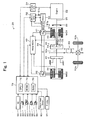
- Fig. 1 schematically illustrates the configuration of a hybrid vehicle 20 in one embodiment of the invention.
- the hybrid vehicle 20 of the embodiment includes the engine 22, a three shaft-type power distribution integration mechanism 30 connected via a damper 28 to a crankshaft 26 functioning as an output shaft of the engine 22, a motor MG1 connected to the power distribution integration mechanism 30 and designed to have power generation capability, a reduction gear 35 attached to a ring gear shaft 32a functioning as a driveshaft linked with the power distribution integration mechanism 30, a motor MG2 connected to the reduction gear 35, inverters 41 and 42 each for driving the motors MG1 and MG2, a battery 50 transmitting electric power to and from the motors MG1 and MG2 via inverters 41 and 42, and a hybrid electronic control unit 70 configured to control the operations of the whole hybrid vehicle 20.
- the engine 22 is constructed as an internal combustion engine designed to consume a hydrocarbon fuel, such as gasoline or light oil, and thereby generate power.
- the engine 22 is under operation controls, such as fuel injection control, ignition control, and intake air flow control, of an engine electronic control unit (hereafter referred to as engine ECU) 24 that inputs diverse signals from various sensors, for example, a crank position from a non-illustrated crank positions sensor to detect the crank angle of the crankshaft 26, used to measure and detect the operating conditions of the engine 22.
- engine ECU engine electronice control unit
- the engine ECU 24 establishes communication with the hybrid electronic control unit 70 to drive and control the engine 22 in response to control signals from the hybrid electronic control unit 70 and with reference to the diverse signals from the various sensors and to output data regarding the operating conditions of the engine 22 to the hybrid electronic control unit 70 according to the requirements.
- the engine ECU 24 also computes a rotation speed of the crankshaft 26, which is equivalent to a rotation speed Ne of the engine 22, based on the crank position from the crank positions sensor.
- the power distribution integration mechanism 30 has a sun gear 31 that is an external gear, a ring gear 32 that is an internal gear and is arranged concentrically with the sun gear 31, multiple pinion gears 33 that engage with the sun gear 31 and with the ring gear 32, and a carrier 34 that holds the multiple pinion gears 33 in such a manner as to allow free revolution thereof and free rotation thereof on the respective axes.
- the power distribution integration mechanism 30 is constructed as a planetary gear mechanism that allows for differential motions of the sun gear 31, the ring gear 32, and the carrier 34 as rotational elements.
- the carrier 34, the sun gear 31, and the ring gear 32 in the power distribution integration mechanism 30 are respectively coupled with the crankshaft 26 of the engine 22, the motor MG1, and the reduction gear 35 via ring gear shaft 32a.
- the motor MG1 functions as a generator
- the power output from the engine 22 and input through the carrier 34 is distributed into the sun gear 31 and the ring gear 32 according to the gear ratio.
- the motor MG1 functions as a motor
- the power output from the engine 22 and input through the carrier 34 is combined with the power output from the motor MG1 and input through the sun gear 31 and the composite power is output to the ring gear 32.
- the power output to the ring gear 32 is thus finally transmitted to the driving wheels 63a and 63b via the gear mechanism 60, and the differential gear 62 from ring gear shaft 32a.
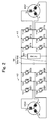
- Each of the motors MG1 and MG2 has a rotor with permanent magnets attached thereto and a stator with three phase coils wound thereon. Both of the motors MG1 and MG2 are constructed as known synchronous motor generators. As shown the schematic structure of an electric driving system including the motors MG1 and MG2 in Fig. 2 , each of the inverters 41 and 42 has six transistors T11 to T16 or T21 to T26 and six diodes D11 to D16 or D21 to D26 connected in inverse parallel with the transistors T11 to T16 or T21 to T26.
- the six transistors T11 to T16 or T21 to T26 are arranged in pairs, so that two transistors in each pair respectively work as a source side and a sink side to a positive electrode bus line 54a and to a negative electrode bus line 54b of the power lines 54.
- the three-phase coils (U phase, V phase, and W phase) of the motors MG1 and MG2 are respectively connected to connection points of the corresponding three pairs of the transistors.
- Controlling the rate of the ON time of the transistors T11 to T16 or T21 to T26 arranged in pairs with application of a voltage between the positive electrode bus line 54a and the negative electrode bus line 54b of the power lines 54 forms a rotating magnetic field on the three-phase coils to rotate and drive the motor MG1 or the motor MG2.
- the inverters 41 and 42 share the positive electrode bus line 54a and the negative electrode bus line 54b. Such connection enables electric power generated by one of the motors MG1 and MG2 to be supply to the other. Operations of both of the motors MG1 and MG2 are controlled by a motor electronic control unit (hereafter referred to as motor ECU) 40.
- motor ECU motor electronice control unit
- the motor ECU 40 inputs diverse signals required for controlling the operations of the motors MG1 and MG2, for example, signals from rotational position detection sensors 43 and 44 that detect the rotational positions of rotors in the motors MG1 and MG2 and phase currents applied to the motors MG1 and MG2 and measured by current sensors (not shown).
- the motor ECU 40 outputs switching control signals to the inverters 41 and 42.
- the motor ECU 40 communicates with the hybrid electronic control unit 70 to control operations of the motors MG1 and MG2 in response to control signals transmitted from the hybrid electronic control unit 70 while outputting data relating to the operating conditions of the motors MG1 and MG2 to the hybrid electronic control unit 70 according to the requirements.
- the motor ECU 40 also performs arithmetic operations to compute rotation speeds Nm1 and Nm2 of the motors MG1 and MG2 from the output signals of the rotational position detection sensors 43 and 44.
- the battery 50 is constructed as a lithium ion secondary battery and under control of a battery electronic control unit (hereafter referred to as battery ECU) 52.
- the battery ECU 52 inputs diverse signals required for control of the battery 50, for example, an inter-terminal voltage Vb measured by a voltage sensor 51a disposed between terminals of the battery 50, a charge-discharge current Ib measured by a current sensor 51b attached to the power line 54 connected with the output terminal of the battery 50, and a battery temperature Tb measured by a temperature sensor 51c attached to the battery 50.
- the battery ECU 52 outputs data relating to the state of the battery 50 to the hybrid electronic control unit 70 via communication according to the requirements.
- the battery ECU 52 also performs various arithmetic operations for management and control of the battery 50.
- An accumulated charge ratio SOC of the battery 50 as a ratio of an accumulated charge amount in the battery 50 to the total capacity (storage capacity) of the battery 50 is calculated from an integrated value of the charge-discharge current Ib measured by the current sensor 51b.
- An input limit Win as an allowable charging electric power to be charged in the battery 50 and an output limit Wout as an allowable discharging electric power to be discharged from the battery 50 are set corresponding to the calculated accumulated charge ratio SOC and the battery temperature Tb.
- a concrete procedure of setting the input and output limits Win and Wout of the battery 50 sets base values of the input limit Win and the output limit Wout corresponding to the battery temperature Tb, specifies an input limit correction factor and an output limit correction factor corresponding to the accumulated charge ratio SOC of the battery 50, and multiplies the base values of the input limit Win and the output limit Wout by the specified input limit correction factor and output limit correction factor to determine the input limit Win and the output limit Wout of the battery 50.
- the hybrid electronic control unit 70 is constructed as a microprocessor including a CPU 72, a ROM 74 that stores processing programs, a RAM 76 that temporarily stores data, and a non-illustrated input-output port, and a non-illustrated communication port.
- the hybrid electronic control unit 70 receives various inputs via the input port: an ignition signal from an ignition switch 80, a gearshift position SP from a gearshift position sensor 82 that detects the current position of a gearshift lever 81, an accelerator opening Acc from an accelerator pedal position sensor 84 that measures a step-on amount of an accelerator pedal 83, a brake pedal position BP from a brake pedal position sensor 86 that measures a step-on amount of a brake pedal 85, an operating signal from a parking brake sensor 88 that detects an operating state of a parking brake pedal 87 for operating a foot-operated parking brake (not shown), and a vehicle speed V from a vehicle speed sensor 89.
- the hybrid electronic control unit 70 outputs control signals to a display 90 that displays variety of information via the output port.
- the hybrid electronic control unit 70 communicates with the engine ECU 24, the motor ECU 40, and the battery ECU 52 via the communication port to transmit diverse control signals and data to and from the engine ECU 24, the motor ECU 40, and the battery ECU 52, as mentioned previously.
- the gearshift position SP detected by the gearshift position sensor 82 has multiple different options: parking position (P position), neutral position (N position), drive position (D position), and reverse position (R position).
- the hybrid vehicle 20 of the embodiment thus constructed calculates a torque command to be output to the ring gear shaft 32a functioning as the driveshaft, based on observed values of a vehicle speed V and an accelerator opening Acc, which corresponds to a driver' s step-on amount of an accelerator pedal 83.
- the engine 22 and the motors MG1 and MG2 are subjected to operation control to output a required level of power corresponding to the calculated torque command to the ring gear shaft 32a.
- the operation control of the engine 22 and the motors MG1 and MG2 selectively effectuates one of a torque conversion drive mode, a charge-discharge drive mode, and a motor drive mode.
- the torque conversion drive mode controls the operations of the engine 22 to output a quantity of power equivalent to the required level of power, while driving and controlling the motors MG1 and MG2 to cause all the power output from the engine 22 to be subjected to torque conversion by means of the power distribution integration mechanism 30 and the motors MG1 and MG2 and output to the ring gear shaft 32a.
- the charge-discharge drive mode controls the operations of the engine 22 to output a quantity of power equivalent to the sum of the required level of power and a quantity of electric power consumed by charging the battery 50 or supplied by discharging the battery 50, while driving and controlling the motors MG1 and MG2 to cause all or part of the power output from the engine 22 equivalent to the required level of power to be subjected to torque conversion by means of the power distribution integration mechanism 30 and the motors MG1 and MG2 and output to the ring gear shaft 32a, simultaneously with charge or discharge of the battery 50.
- the motor drive mode stops the operations of the engine 22 and drives and controls the motor MG2 to output a quantity of power equivalent to the required level of power to the ring gear shaft 32a.
- Fig. 3 is a flowchart showing a N position control routine executed by the hybrid electronic control unit 70. This routine is performed repeatedly when the gearshift position SP is the N position. A case that the gearshift position SP is set to the N position during stop of the engine 22 is described below.
- the inverters 41 and 42 are shut off (all of the transistors T11 to T16 and T21 to T26 are switched to an off state) in response to the gearshift position SP set to the N position.
- the CPU 72 of the hybrid electronic control unit 70 inputs various data, for example, an engine operation flag Fe that shows whether the engine 22 is operated or not, a brake flag Fb that shows whether a vehicle stop is held (hereafter this state is referred to as a stop held state) or not, the accumulated charge ratio SOC of the battery 50 (step S100).
- the engine operation flag Fe is set to value '1' when the engine 22 is operated, set to value '0' when the engine 22 is not operated, and input from the engine ECU 24 by communication.
- the brake flag Fb is set to value '1' when the vehicle stop is held, set to value '0' when the vehicle stop is not held, and input, by the hybrid electronic control unit 70.
- whether the vehicle state is the stop held state or not is determined according to the brake pedal position BP from the brake pedal position sensor 86, and lock information.
- the lock information is obtained based on the operating signals from the parking brake sensor 88, and shows whether the driving wheels 63a and 63b are locked by the parking brake (not shown). Specifically, it is determined the vehicle state is the stop held state, when the brake pedal position BP is more than or equal to a threshold value BPref (for example, 40% or 50 %) or when the driving wheels 63a and 63b are locked by the parking brake.
- the accumulated charge ratio SOC of the battery 50 is calculated from the integrated value of the charge-discharge current Ib measured by the current sensor 51b and input from the battery ECU 52 by communication.
- the CPU 72 checks the value of the charge control flag Fc (step S110).
- the charge control flag Fc is set to value '1' when a charge control is performed, and set to value '0' when the charge control is not performed.
- the charge control is a control where the engine 22 and the motor MG1 are controlled to charge the battery 50 at the state that the gearshift position SP is the N position.
- the CPU 72 compares the accumulated charge ratio SOC of the battery 50 with a threshold value Slow (step S120).
- the threshold value Slow is set as a upper limit of the accumulated charge ratio SOC required to start the charge control, and set to, for example, 25% or 30%.
- the CPU 72 determines the start of the charge control is not required, and sets the charge control flag F to value '0' (step S170). This routine is terminated.
- the CPU 72 determines the start of the charge control is required, checks the value of the engine operation flag Fe (step S130). When the engine operation flag Fe is value '0', that is, when the engine 22 is not operated, the CPU 72 checks the value of the brake flag Fb (step S140).
- the CPU 72 sends control signal for stating the engine 22 to the motor ECU 40 and the engine ECU 24 (step S150), and sets the charge control flag Fc to value '0' (step S170).
- This routine is terminated.
- the motor ECU 40 controls the motor MG1 to output a torque for cranking the engine 22 from the motor MG1, in response to reception of the control signal for stating the engine 22.
- the engine ECU 24 starts fuel injection and ignition when the rotation speed Ne of the engine 22 reaches to a threshold value Nref (for example, 1000rpm or 1200rpm) to start the engine 22, in response to reception of the control signal for stating the engine 22.
- Nref for example, 1000rpm or 1200rpm
- the CPU 72 outputs warning information (for example, 'Please step on brake pedal' or 'Please switch parking brake to ON') to the display 90, so that the vehicle state changes to the stop held state by the drive stepping on the brake pedal 85 or the parking brake pedal 87 (step S160), and sets the charge control flag Fc to value '0' (step S170). This routine is terminated.
- warning information for example, 'Please step on brake pedal' or 'Please switch parking brake to ON'
- step S140 when the brake flag Fb becomes to value '1' by the driver stepping on the brake pedal 85 or the parking brake pedal 87 (step S140), the CPU 72 sends the control signal for starting the engine 22 to the motor ECU 40 and the engine ECU 24 to start the engine 22 (step S150).
- the CPU 72 determines the engine operation flag Fe is value '1' at step S130, sends a shutoff command of the inverter 41 for driving the motor MG1 to the motor ECU 40 (step S180), sets a target rotation speed Ne* used in the performance of a self-sustained operation of the engine 22 to a rotation speed N1 that is relatively high (step S190), sends the set target rotation speed Ne* and a self-sustained operation command of the engine 22 to the engine ECU 24 (step S200), and sets the charge control flag Fc to value '1' (step S210). This routine is terminated.
- the engine ECU 24 In response to reception of the set target rotation speed Ne* and the self-sustained operation demand, the engine ECU 24 performs required controls including the intake air flow control, the fuel injection control, the ignition control of the engine 22 to perform the self-sustained operation of the engine 22 at the set target rotation speed Ne*.
- the rotation speed N1 is set within the rotation speed range that back electromotive force generated with rotation of the motor MG1 is more than a voltage applied to the inverters 41 and 42.
- Fig. 4 is an alignment chart showing rotation speed dynamics of the respective rotational elements included in the power distribution integration mechanism 30 during the shutoff of both of the inverters 41 and 42.
- the left axis 'S' represents a rotation speed of the sun gear 31 that is equivalent to the rotation speed Nm1 of the motor MG1.
- the middle axis 'C' represents a rotation speed of the carrier 34 that is equivalent to the rotation speed Ne of the engine 22.
- the right axis 'R' represents the rotation speed Nr (value '0') of the ring gear 32 obtained by dividing the rotation speed Nm2 of the motor MG2 by the gear ratio Gr of the reduction gear 35.
- the motor MG1 rotates at a rotation speed according to the rotation speed dynamics (a gear ratio p) on the respective rotational elements included in the power distribution integration mechanism 30, and the back electromotive force generates on the motor MG1 with the rotation of the motor MG1.
- the greater rotation speed of the motor MG1 causes the greater back electromotive force.
- the back electromotive force is less than or equal to the voltage applied to the inverters 41 and 42 in the state that the inverter 41 is shut off, the current caused by the back electromotive force does not flow to the power lines 54.
- the diodes D11 to D16 of the inverter 41 function as a full-wave rectifier circuit and thereby the current caused by the back electromotive force flows to the power lines 54 to charge the battery 50.
- the rotation speed N1 is set within the rotation speed range that the battery 50 is charged, and set to, for example, 3000rpm, 3500rpm or 4000rpm. Performing the self-sustained operation of the engine 22 at the rotation speed N1 enables to charge the battery 50 with the back electromotive force generated with the rotation of the motor MG1.
- the CPU 72 compares the accumulated charge ratio SOC with a threshold value Shi (step S220).
- the threshold value Shi is set as a lower limit of the accumulated charge ratio SOC required to stop the charge control, and set to, for example, 45% or 50%.
- the CPU 72 executes the processing of steps S180 to S210. This routine is terminated. This causes the continuation of charge of the battery 50.
- the CPU 72 determines the stop of the charge control is required, the CPU 72 sends control signal for stopping the operation of the engine 22 to the engine ECU 24 (step S230), and sets the charge control flag Fc to value '0' (step S240). This routine is terminated.
- the engine ECU 24 stops the control of the engine 22. This causes the stop of the charge of the battery 50. Stopping the operation of the engine 22 when the accumulated charge ratio SOC of the battery 50 is more than or equal to the threshold value Shi enables to prevent waste fuel consumption, in comparison with continuing that the operation of the engine 22 when the battery 50 is not charged. In this arrangement, the Shutoff of the inverters 41 and 42 is continued.
- the engine 22 when the gearshift position SP is the N position and the accumulated charge ratio SOC of the battery 50 is less than or equal to the threshold value Slow, the engine 22 is cranked by the motor MG1 and started in the case that the vehicle stop is held, and the shutoff of the inverter 41 is performed and the self-sustained operation of the engine 22 is performed at the rotation speed N1 at which the back electromotive force generated on the motor MG1 is more than the voltage applied to the inverters 41 and 42 after the engine 22 is started.
- This enables, in comparison with a case that the engine 22 is immediately started after the gearshift position SP set to the N position, to prevent the fuel consumption of the engine 22 before the start of charge of the battery 50.
- This also enables to charge the battery 50 with the back electromotive force generated on the motor MG1 after the engine 22 is started.
- the discussion is made in the case that the gearshift position SP is set to the N position during the stop of the operation of the engine 22.
- the engine 22 may be stopped, and then the engine 22 may be started as the condition that the vehicle stop is held when the accumulated charge ratio SOC of the battery 50 becomes less than or equal to the threshold value Slow, as well as the embodiment. This accordingly enables to exert the similar effects to those of the embodiment.
- whether the vehicle state is the stop held state or not is determined using the brake pedal position BP and the lock information that shows whether the driving wheels 63a and 63b are locked by the parking brake or not.
- the parking brake is the foot-operated type for locking or unlocking the drive wheels 63a and 63b. This is not essential, and the parking brake may be a lever type or a switch type, by hand.
- the battery 50 is charged with the back electromotive force generated on the motor MG1 by the performance of the self-sustained operation of the engine 22 at the rotation speed N1.
- the battery 50 may be charged with electricity power that is generated by the motor MG1 using the power from the engine 22.
- Fig. 5 is a flowchart showing a N position control routine executed in one modified example. This routine is same as the N position control routine of Fig.
- the CPU 72 sets the target rotation speed Ne* of the engine 22 to the predetermined rotation speed Nch (for example, 2000rpm or 2500rpm) as a rotation speed for charging the battery 50, sets the target torque Te* of the engine 22 to the predetermined torque Tch as a torque for charging the battery 50, and sends the set target rotation speed Ne* and the set target torque Te* to the engine ECU 24 (step S310).
- Nch for example, 2000rpm or 2500rpm
- the CPU 72 subsequently sets the torque command Tm1* of the motor MG1 to a torque calculated from the set target toque Te* and the gear ratio p of the power distribution integration mechanism 30 according to Equation (1) given below, and sends the set torque command Tm1* to the motor ECU 40 (step S320), and sets the charge flag Fc to value '1' (step S210).
- This routine is terminated.
- This enables to charge the battery 50 with the electric power that is generated by the motor MG1 using the power from the engine 22.
- this modified example enables to prevent to give feeling of incompatibility to a driver due to rev up the rotation speed Ne of the engine 22. Equation (1) is readily introduced from the alignment chart of Fig. 4 described above.
- Tm ⁇ 1 * - ⁇ ⁇ Te * / 1 + ⁇
- the operation of the engine 22 is stopped, but the engine 22 may be operated at a rotation speed N2 that is less than the rotation speed N1.
- the rotation speed N2 may be set within the rotation speed range that the back electromotive force generated on the motor MG1 is less than or equal to the voltage VH of the high voltage system, and set to, for example, 1000rpm or 1200rpm. In this arrangement, stopping the operation of the engine 22 as well as the embodiment until the requirement of the start of the charge control after the gearshift position SP set to the N position enables to prevent the fuel consumption.
- the warning information (for example, text or image such as 'Please step on brake pedal' or 'Please switch parking brake to ON') is output to the display 90.
- the warning information may be output from speaker (not shown), in addition to or in place of output to the display 90.
- the warning information may not be output.
- the power of the motor MG2 is converted by the reduction gear 35 and is output to the ring gear shaft 32a.
- the technique of the invention is also applicable to a hybrid vehicle 120 of a modified structure shown in Fig. 6 .
- the power of the motor MG2 is connected to another axle (an axle linked with wheels 64a and 64b) that is different from the axle connecting with the ring gear shaft 32a (the axle linked with the drive wheels 63a and 63b).
- the power of the engine 22 is output via the power distribution integration mechanism 30 to the ring gear shaft 32a or the driveshaft linked with the drive wheels 63a and 63b.
- the technique of the invention is also applicable to a hybrid vehicle 220 of a modified structure shown in Fig. 7 .
- the motor MG1 for power generation is connected with the engine 22
- the motor MG2 is connected with the drive wheels 63a and 63b
- the battery 50 is connected with the inverters 41 and 42 that drive the motors MG1 and MG2.
- the invention is described using an application to a hybrid vehicle.
- the invention may be applied to a control method of a hybrid vehicle.
- the primary elements in the embodiment and its modified examples are mapped to the primary constituents in the claims of the invention as described below.
- the engine 22 corresponds to the 'internal combustion engine' in the claims of the invention.
- the motor MG1 corresponds to the 'generator' in the claims of the invention.
- the inverter 41 corresponds to the 'generator inverter circuit' in the claims of the invention.
- the motor MG2 corresponds to the 'motor' in the claims of the invention.
- the inverter 42 corresponds to the 'motor inverter circuit' in the claims of the invention.
- the battery 50 corresponds to the 'secondary battery' in the claims of the invention.
- the battery ECU 52 that calculates the accumulated charge ratio SOC of the battery 50 from an integrated value of the charge-discharge current Ib of the battery 50 corresponds to the 'accumulated charge ratio detecting module' in the claims of the invention.
- a combination of the hybrid electronic control unit 70, the engine ECU 24 and the motor ECU 40 corresponds to the 'control module' in the claims of the invention.
- the hybrid electronic control unit 70 when the gearshift position SP is the N position and the accumulated charge ratio SOC of the battery 50 is less than or equal to the threshold value Slow, sends the control signal for starting the engine 22 to the motor ECU 24 and the engine ECU 24 in the case that the vehicle stop is held.
- the hybrid electronic control unit 70 After the engine 22 is started, sends the shutoff command of the inverter 41 to the motor ECU 40, sets the target rotation speed Ne* of the engine 22 to the rotation speed N1 that is relatively low and sends the set target rotation speed Ne* and the self-sustained operation command to the engine ECU 24.
- the motor ECU 40 controls the motor MG1 to output a torque for cranking the engine 22 from the motor MG1 when receiving the control signal for stating the engine 22, performs the shutoff of the inverter 41 when receiving the shutoff command of the inverter 41, and preforms the shutoff the inverter 42 when receiving the shutoff command of the inverter 42.
- the engine ECU 24 starts the fuel injection and the ignition when the rotation speed Ne of the engine 22 reaches to the threshold value Nref after the reception of the control signal for stating the engine 22, and controls the engine 22 to perform the self-sustained operation of the engine 22 when receiving the target rotation speed Ne* and the self-sustained operation demand.
- the power distribution integration mechanism 30 corresponds to the 'planetary gear mechanism' in the claims of the invention.
- the 'internal combustion engine' is not restricted to the internal combustion engine designed to consume a hydrocarbon fuel, such as gasoline or light oil, and thereby output power, but may be any other type, for example, a hydrogen engine.
- the 'generator' is not restricted to the motor MG1 constructed as a synchronous motor generator but may be any type of generator constructed to input and output power from and to an output shaft of the internal combustion engine, to rotate at an rotation speed corresponding to an rotation speed of the internal combustion engine, and to generate back electromotive force with rotation, for example, an induction motor.
- the 'generator inverter circuit' is not restricted to the inverter 41 but may be any type of inverter circuit for driving the generator.
- the 'motor' is not restricted to the motor MG2 constructed as a synchronous motor generator but may be any type of motor constructed to input and output power from and to an axle, for example, an induction motor.
- the 'motor inverter circuit' is not restricted to the inverter 42 but may be any type of inverter circuit for driving the motor.
- the 'secondary battery' is not restricted to the battery 50 constructed as a lithium ion battery but may be any other type of secondary battery transmitting electric power to and from the generator and the motor via the generator inverter circuit and the motor inverter circuit, for example, a nickel metal hydride battery, a nickel cadmium battery, and a lead acid battery.
- the 'accumulated charge ratio detecting module' is not restricted to the arrangement of calculating the accumulated charge ratio SOC of the battery 50 from an integrated value of the charge-discharge current Ib of the battery 50, but may be any other arrangement of detecting an accumulated charge ratio as a ratio of an accumulated charge amount to whole capacity of the secondary battery, for example, an arrangement of calculating the accumulated charge ratio SOC of the battery 50 from an open circuit voltage of the battery 50.
- the 'control module' is not restricted to the combination of the hybrid electronic control unit 70, the engine ECU 24 and the motor ECU 40 but may be actualized by a single electronic control unit.
- the 'control module' is not restricted to the arrangement described below.
- the engine 22 is cranked by the motor MG1 and started in the case that the vehicle stop is held, and then the shutoff of the inverter 41 is performed and the self-sustained operation of the engine 22 is performed at the rotation speed N1 at which the back electromotive force generated on the motor MG1 is more than the voltage applied to the inverters 41 and 42.
- the 'control module' may be any other arrangement of, upon satisfaction of a predetermined condition that the detected accumulated charge ratio is less than or equal to a predetermined accumulated charge ratio in a state that a gearshift position is a neutral position and both of the generator inverter circuit and the motor inverter circuit are shut off, controlling the internal combustion engine and the generator so that the internal combustion engine is cranked by the generator and started in a case that the vehicle stop is held, and controlling the generator inverter circuit to be shut off and the internal combustion engine to be operated at a rotation speed that the back electromotive force generated with the rotation of the generator is more than a voltage applied to the generator inverter circuit after the internal combustion engine is started.
- the 'planetary gear mechanism' is not restricted to the power distribution integration mechanism 30 but may be any other mechanism with three elements each connected to three shafts, a driveshaft linked to the axle, the output shaft of the internal combustion engine, and a rotating shaft of the generator, for example, a structure adopting a double pinion-type planetary gear mechanism, or a structure adopting a combination of multiple planetary gear mechanisms and connected with four or more axes.
- the technique of the invention is preferably applied to the manufacturing industries of the hybrid vehicles.
Landscapes
- Engineering & Computer Science (AREA)
- Transportation (AREA)
- Mechanical Engineering (AREA)
- Chemical & Material Sciences (AREA)
- Combustion & Propulsion (AREA)
- Power Engineering (AREA)
- Sustainable Energy (AREA)
- Life Sciences & Earth Sciences (AREA)
- Sustainable Development (AREA)
- Automation & Control Theory (AREA)
- Electric Propulsion And Braking For Vehicles (AREA)
- Hybrid Electric Vehicles (AREA)
- Control Of Vehicle Engines Or Engines For Specific Uses (AREA)
Applications Claiming Priority (1)
| Application Number | Priority Date | Filing Date | Title |
|---|---|---|---|
| PCT/JP2009/069396 WO2011058654A1 (fr) | 2009-11-13 | 2009-11-13 | Véhicule hybride et son procédé de commande |
Publications (3)
| Publication Number | Publication Date |
|---|---|
| EP2500223A1 true EP2500223A1 (fr) | 2012-09-19 |
| EP2500223A4 EP2500223A4 (fr) | 2014-05-07 |
| EP2500223B1 EP2500223B1 (fr) | 2016-03-30 |
Family
ID=43991333
Family Applications (1)
| Application Number | Title | Priority Date | Filing Date |
|---|---|---|---|
| EP09851284.1A Not-in-force EP2500223B1 (fr) | 2009-11-13 | 2009-11-13 | Véhicule hybride et son procédé de commande |
Country Status (5)
| Country | Link |
|---|---|
| US (1) | US8583309B2 (fr) |
| EP (1) | EP2500223B1 (fr) |
| JP (1) | JP5267677B2 (fr) |
| CN (1) | CN102596671B (fr) |
| WO (1) | WO2011058654A1 (fr) |
Cited By (1)
| Publication number | Priority date | Publication date | Assignee | Title |
|---|---|---|---|---|
| WO2016133453A1 (fr) * | 2015-02-18 | 2016-08-25 | Scania Cv Ab | Procédé et système de commande pour charger un véhicule hybride |
Families Citing this family (34)
| Publication number | Priority date | Publication date | Assignee | Title |
|---|---|---|---|---|
| US10479184B2 (en) * | 2010-09-30 | 2019-11-19 | Evaos, Inc. | Auxiliary electric drive system and vehicle using same |
| CN103155347B (zh) * | 2010-12-13 | 2015-06-24 | 三洋电机株式会社 | 充电设备、电力存储设备以及电源设备 |
| DE102011012164A1 (de) * | 2011-02-23 | 2012-08-23 | Bombardier Transportation Gmbh | Anordnung und Verfahren zum Versorgen von elektrischen Traktionsmotoren in einem Schienenfahrzeug, insbesondere in einem Zugverband, mit elektrischer Energie |
| US9145893B2 (en) * | 2011-06-08 | 2015-09-29 | Bendix Commercial Vehicle Systems Llc | Current control via speed control for driving screw compressor under cold conditions |
| US20140232179A1 (en) * | 2011-09-26 | 2014-08-21 | Toyota Jidosha Kabushiki Kaisha | Vehicle and method of controlling vehicle |
| CN104169117B (zh) * | 2012-03-12 | 2016-06-15 | 丰田自动车株式会社 | 混合动力车辆的发电控制装置 |
| JPWO2013186924A1 (ja) * | 2012-06-15 | 2016-02-01 | トヨタ自動車株式会社 | ハイブリッド車両用駆動装置 |
| SE1200394A1 (sv) * | 2012-06-27 | 2013-12-28 | Scania Cv Ab | Drivsystem och förfarande för att driva ett fordon |
| SE538161C2 (sv) * | 2012-06-27 | 2016-03-22 | Scania Cv Ab | Drivsystem och förfarande för att driva ett fordon |
| US9108628B2 (en) * | 2012-08-31 | 2015-08-18 | GM Global Technology Operations LLC | Turbo compounding hybrid generator powertrain |
| US20140095002A1 (en) * | 2012-10-03 | 2014-04-03 | David Crecelius | Electric Hybrid Drive for Retrofitting to Internal Combustion Automobiles |
| CN104071019B (zh) * | 2013-03-28 | 2017-02-22 | 比亚迪股份有限公司 | 燃油车辆及其的电池的自动充电控制方法及自动充电系统 |
| DE102013013954A1 (de) * | 2013-08-21 | 2015-02-26 | Audi Ag | Antriebsvorrichtung für ein Hybridfahrzeug |
| US9145133B2 (en) * | 2013-11-08 | 2015-09-29 | Ford Global Technologies, Llc | Method and system for selecting an engine operating point for a hybrid vehicle |
| US9481256B2 (en) * | 2014-01-30 | 2016-11-01 | Amp Electric Vehicles Inc. | Onboard generator drive system for electric vehicles |
| US9475479B2 (en) * | 2014-04-29 | 2016-10-25 | Ford Global Technologies, Llc | Electrified vehicle neutral engine start |
| JP6359875B2 (ja) * | 2014-05-28 | 2018-07-18 | トヨタ自動車株式会社 | ハイブリッド自動車 |
| CN105197013B (zh) * | 2014-06-30 | 2017-11-21 | 比亚迪股份有限公司 | 车辆的启动控制方法、装置和车辆 |
| US9493063B2 (en) * | 2014-07-16 | 2016-11-15 | GM Global Technology Operations LLC | Method to allow trickle-charging on a strong hybrid vehicle to balance accessory loads |
| CN105620467B (zh) * | 2014-10-31 | 2018-08-14 | 比亚迪股份有限公司 | 混合动力车辆及混合动力车辆的驱动控制方法 |
| CN104828065B (zh) * | 2014-11-24 | 2017-10-10 | 北汽福田汽车股份有限公司 | 混合动力汽车及其充电控制方法 |
| JP6311675B2 (ja) * | 2014-11-28 | 2018-04-18 | トヨタ自動車株式会社 | 車載二次電池の充放電制御装置 |
| JP6332172B2 (ja) * | 2015-07-06 | 2018-05-30 | トヨタ自動車株式会社 | ハイブリッド自動車 |
| JP6426584B2 (ja) * | 2015-11-02 | 2018-11-21 | トヨタ自動車株式会社 | ハイブリッド車両 |
| US10836372B2 (en) * | 2016-08-24 | 2020-11-17 | Ford Global Technologies, Llc | System and method for controlling a hybrid vehicle in park or neutral |
| US10035414B1 (en) * | 2017-01-18 | 2018-07-31 | GM Global Technology Operations LLC | Automatically-shiftable hybrid transaxle |
| CN106891729B (zh) * | 2017-03-21 | 2020-01-21 | 北京新能源汽车股份有限公司 | 一种车辆下电控制方法、装置及汽车 |
| JP6772965B2 (ja) * | 2017-06-08 | 2020-10-21 | トヨタ自動車株式会社 | 車両の制御装置 |
| JP6844492B2 (ja) * | 2017-10-10 | 2021-03-17 | 株式会社デンソー | シフトレンジ制御装置 |
| CN114248630B (zh) * | 2020-09-23 | 2024-04-19 | 广汽埃安新能源汽车有限公司 | 一种电动汽车的防溜坡驻车控制方法、整车控制器、介质 |
| JP7472847B2 (ja) * | 2021-04-22 | 2024-04-23 | トヨタ自動車株式会社 | 自動車 |
| CN113833579B (zh) * | 2021-11-25 | 2022-04-12 | 北汽福田汽车股份有限公司 | 控制发动机的方法、装置、电子设备和车辆 |
| CN114228471A (zh) * | 2022-01-10 | 2022-03-25 | 无锡明恒混合动力技术有限公司 | 一种采用机械空调的混合动力系统及其控制方法 |
| CN115009258B (zh) * | 2022-06-13 | 2025-09-09 | 中国第一汽车股份有限公司 | 一种动力电池的充电请求确定方法、确定装置和控制器 |
Family Cites Families (13)
| Publication number | Priority date | Publication date | Assignee | Title |
|---|---|---|---|---|
| JPH11348607A (ja) | 1998-06-12 | 1999-12-21 | Toyota Motor Corp | エンジンの自動停止始動装置 |
| JP2003176867A (ja) | 2001-12-11 | 2003-06-27 | Toyota Motor Corp | シフト制御装置 |
| JP3933106B2 (ja) * | 2003-07-30 | 2007-06-20 | トヨタ自動車株式会社 | 動力出力装置およびその制御方法並びに自動車 |
| JP4074629B2 (ja) | 2005-06-23 | 2008-04-09 | 三菱電機株式会社 | エンジン停止始動制御装置 |
| KR100748659B1 (ko) * | 2005-12-01 | 2007-08-10 | 현대자동차주식회사 | 하이브리드 자동차의 중립레인지에서의 충전 방법 및 상기 방법을 사용하는 하이브리드 자동차 |
| JP2007284005A (ja) | 2006-04-20 | 2007-11-01 | Toyota Motor Corp | 車両及びその制御方法 |
| JP4232824B2 (ja) * | 2006-12-28 | 2009-03-04 | トヨタ自動車株式会社 | ハイブリッド自動車およびその制御方法 |
| JP4229185B2 (ja) * | 2007-01-12 | 2009-02-25 | トヨタ自動車株式会社 | ハイブリッド自動車およびその制御方法 |
| JP4833096B2 (ja) | 2007-01-19 | 2011-12-07 | トヨタ自動車株式会社 | ハイブリッド車両、ハイブリッド車両の制御方法およびハイブリッド車両の制御方法をコンピュータに実行させるためのプログラムを記録したコンピュータ読取可能な記録媒体 |
| JP5082669B2 (ja) * | 2007-08-10 | 2012-11-28 | トヨタ自動車株式会社 | ハイブリッド車両用動力伝達装置の制御装置 |
| JP4341717B2 (ja) * | 2008-01-31 | 2009-10-07 | トヨタ自動車株式会社 | 車両の駆動装置およびその制御方法 |
| JP2009184500A (ja) | 2008-02-06 | 2009-08-20 | Toyota Motor Corp | 車両およびその制御方法 |
| JP2009248940A (ja) | 2008-04-11 | 2009-10-29 | Toyota Motor Corp | 車両およびその制御方法 |
-
2009
- 2009-11-13 WO PCT/JP2009/069396 patent/WO2011058654A1/fr not_active Ceased
- 2009-11-13 JP JP2011540375A patent/JP5267677B2/ja not_active Expired - Fee Related
- 2009-11-13 US US13/509,199 patent/US8583309B2/en not_active Expired - Fee Related
- 2009-11-13 EP EP09851284.1A patent/EP2500223B1/fr not_active Not-in-force
- 2009-11-13 CN CN200980162406.7A patent/CN102596671B/zh not_active Expired - Fee Related
Cited By (2)
| Publication number | Priority date | Publication date | Assignee | Title |
|---|---|---|---|---|
| WO2016133453A1 (fr) * | 2015-02-18 | 2016-08-25 | Scania Cv Ab | Procédé et système de commande pour charger un véhicule hybride |
| US10752251B2 (en) | 2015-02-18 | 2020-08-25 | Scania Cv Ab | Method and control system for charging a hybrid vehicle |
Also Published As
| Publication number | Publication date |
|---|---|
| EP2500223B1 (fr) | 2016-03-30 |
| JPWO2011058654A1 (ja) | 2013-03-28 |
| JP5267677B2 (ja) | 2013-08-21 |
| WO2011058654A1 (fr) | 2011-05-19 |
| US8583309B2 (en) | 2013-11-12 |
| US20120226406A1 (en) | 2012-09-06 |
| CN102596671B (zh) | 2014-07-16 |
| EP2500223A4 (fr) | 2014-05-07 |
| CN102596671A (zh) | 2012-07-18 |
Similar Documents
| Publication | Publication Date | Title |
|---|---|---|
| EP2500223B1 (fr) | Véhicule hybride et son procédé de commande | |
| US9027680B2 (en) | Hybrid vehicle and control method thereof | |
| KR100491572B1 (ko) | 자동차 | |
| US8118704B2 (en) | Vehicle and control method of vehicle | |
| US20100318249A1 (en) | Vehicle and control method thereof | |
| US7694763B2 (en) | Vehicle and its control method | |
| EP3209514B1 (fr) | Automobile comprenant un moteur permettant de faire fonctionner l'automobile | |
| US10836396B2 (en) | Hybrid vehicle | |
| US10086821B2 (en) | Hybrid vehicle | |
| US10919516B2 (en) | Hybrid vehicle | |
| JP2009184500A (ja) | 車両およびその制御方法 | |
| US10442424B2 (en) | Hybrid vehicle | |
| JP5565256B2 (ja) | ハイブリッド自動車および情報出力方法 | |
| JP4222332B2 (ja) | ハイブリッド車およびその制御方法 | |
| JP2008254677A (ja) | 車両及びその制御方法 | |
| JP2021011137A (ja) | ハイブリッド車両 | |
| JP2012130098A (ja) | 電動車両 | |
| JP3984229B2 (ja) | 動力出力装置およびこれを搭載した自動車並びにその制御方法 | |
| JP2007230366A (ja) | 動力出力装置、それを搭載する車両及び動力出力装置の制御方法 | |
| JP4492605B2 (ja) | 動力出力装置およびその制御方法並びに車両 | |
| JP4281706B2 (ja) | ハイブリッド自動車およびその制御方法 | |
| JP2007237821A (ja) | 動力出力装置およびこれを搭載する車両ならびに動力出力装置の制御方法 | |
| US20180001787A1 (en) | Motor vehicle |
Legal Events
| Date | Code | Title | Description |
|---|---|---|---|
| PUAI | Public reference made under article 153(3) epc to a published international application that has entered the european phase |
Free format text: ORIGINAL CODE: 0009012 |
|
| 17P | Request for examination filed |
Effective date: 20120327 |
|
| AK | Designated contracting states |
Kind code of ref document: A1 Designated state(s): AT BE BG CH CY CZ DE DK EE ES FI FR GB GR HR HU IE IS IT LI LT LU LV MC MK MT NL NO PL PT RO SE SI SK SM TR |
|
| DAX | Request for extension of the european patent (deleted) | ||
| RAP1 | Party data changed (applicant data changed or rights of an application transferred) |
Owner name: TOYOTA JIDOSHA KABUSHIKI KAISHA |
|
| A4 | Supplementary search report drawn up and despatched |
Effective date: 20140404 |
|
| RIC1 | Information provided on ipc code assigned before grant |
Ipc: B60L 11/18 20060101ALI20140331BHEP Ipc: B60L 3/04 20060101ALI20140331BHEP Ipc: B60K 6/445 20071001ALI20140331BHEP Ipc: B60L 15/20 20060101ALI20140331BHEP Ipc: B60W 30/192 20120101ALI20140331BHEP Ipc: B60L 15/00 20060101ALI20140331BHEP Ipc: B60W 30/18 20120101ALI20140331BHEP Ipc: B60W 10/06 20060101AFI20140331BHEP Ipc: B60L 11/14 20060101ALI20140331BHEP Ipc: B60W 20/00 20060101ALI20140331BHEP Ipc: B60L 11/12 20060101ALI20140331BHEP Ipc: B60W 10/08 20060101ALI20140331BHEP Ipc: B60K 6/52 20071001ALI20140331BHEP Ipc: B60W 10/26 20060101ALI20140331BHEP |
|
| GRAP | Despatch of communication of intention to grant a patent |
Free format text: ORIGINAL CODE: EPIDOSNIGR1 |
|
| INTG | Intention to grant announced |
Effective date: 20150922 |
|
| GRAS | Grant fee paid |
Free format text: ORIGINAL CODE: EPIDOSNIGR3 |
|
| GRAA | (expected) grant |
Free format text: ORIGINAL CODE: 0009210 |
|
| AK | Designated contracting states |
Kind code of ref document: B1 Designated state(s): AT BE BG CH CY CZ DE DK EE ES FI FR GB GR HR HU IE IS IT LI LT LU LV MC MK MT NL NO PL PT RO SE SI SK SM TR |
|
| REG | Reference to a national code |
Ref country code: GB Ref legal event code: FG4D |
|
| REG | Reference to a national code |
Ref country code: CH Ref legal event code: EP |
|
| REG | Reference to a national code |
Ref country code: AT Ref legal event code: REF Ref document number: 785028 Country of ref document: AT Kind code of ref document: T Effective date: 20160415 |
|
| REG | Reference to a national code |
Ref country code: IE Ref legal event code: FG4D |
|
| REG | Reference to a national code |
Ref country code: DE Ref legal event code: R096 Ref document number: 602009037441 Country of ref document: DE |
|
| REG | Reference to a national code |
Ref country code: LT Ref legal event code: MG4D |
|
| PG25 | Lapsed in a contracting state [announced via postgrant information from national office to epo] |
Ref country code: FI Free format text: LAPSE BECAUSE OF FAILURE TO SUBMIT A TRANSLATION OF THE DESCRIPTION OR TO PAY THE FEE WITHIN THE PRESCRIBED TIME-LIMIT Effective date: 20160330 Ref country code: NO Free format text: LAPSE BECAUSE OF FAILURE TO SUBMIT A TRANSLATION OF THE DESCRIPTION OR TO PAY THE FEE WITHIN THE PRESCRIBED TIME-LIMIT Effective date: 20160630 Ref country code: HR Free format text: LAPSE BECAUSE OF FAILURE TO SUBMIT A TRANSLATION OF THE DESCRIPTION OR TO PAY THE FEE WITHIN THE PRESCRIBED TIME-LIMIT Effective date: 20160330 Ref country code: GR Free format text: LAPSE BECAUSE OF FAILURE TO SUBMIT A TRANSLATION OF THE DESCRIPTION OR TO PAY THE FEE WITHIN THE PRESCRIBED TIME-LIMIT Effective date: 20160701 |
|
| REG | Reference to a national code |
Ref country code: NL Ref legal event code: MP Effective date: 20160330 |
|
| REG | Reference to a national code |
Ref country code: AT Ref legal event code: MK05 Ref document number: 785028 Country of ref document: AT Kind code of ref document: T Effective date: 20160330 |
|
| PG25 | Lapsed in a contracting state [announced via postgrant information from national office to epo] |
Ref country code: SE Free format text: LAPSE BECAUSE OF FAILURE TO SUBMIT A TRANSLATION OF THE DESCRIPTION OR TO PAY THE FEE WITHIN THE PRESCRIBED TIME-LIMIT Effective date: 20160330 Ref country code: LT Free format text: LAPSE BECAUSE OF FAILURE TO SUBMIT A TRANSLATION OF THE DESCRIPTION OR TO PAY THE FEE WITHIN THE PRESCRIBED TIME-LIMIT Effective date: 20160330 Ref country code: LV Free format text: LAPSE BECAUSE OF FAILURE TO SUBMIT A TRANSLATION OF THE DESCRIPTION OR TO PAY THE FEE WITHIN THE PRESCRIBED TIME-LIMIT Effective date: 20160330 |
|
| REG | Reference to a national code |
Ref country code: DE Ref legal event code: R084 Ref document number: 602009037441 Country of ref document: DE |
|
| PG25 | Lapsed in a contracting state [announced via postgrant information from national office to epo] |
Ref country code: NL Free format text: LAPSE BECAUSE OF FAILURE TO SUBMIT A TRANSLATION OF THE DESCRIPTION OR TO PAY THE FEE WITHIN THE PRESCRIBED TIME-LIMIT Effective date: 20160330 |
|
| PG25 | Lapsed in a contracting state [announced via postgrant information from national office to epo] |
Ref country code: PL Free format text: LAPSE BECAUSE OF FAILURE TO SUBMIT A TRANSLATION OF THE DESCRIPTION OR TO PAY THE FEE WITHIN THE PRESCRIBED TIME-LIMIT Effective date: 20160330 Ref country code: IS Free format text: LAPSE BECAUSE OF FAILURE TO SUBMIT A TRANSLATION OF THE DESCRIPTION OR TO PAY THE FEE WITHIN THE PRESCRIBED TIME-LIMIT Effective date: 20160730 Ref country code: EE Free format text: LAPSE BECAUSE OF FAILURE TO SUBMIT A TRANSLATION OF THE DESCRIPTION OR TO PAY THE FEE WITHIN THE PRESCRIBED TIME-LIMIT Effective date: 20160330 |
|
| PG25 | Lapsed in a contracting state [announced via postgrant information from national office to epo] |
Ref country code: SM Free format text: LAPSE BECAUSE OF FAILURE TO SUBMIT A TRANSLATION OF THE DESCRIPTION OR TO PAY THE FEE WITHIN THE PRESCRIBED TIME-LIMIT Effective date: 20160330 Ref country code: ES Free format text: LAPSE BECAUSE OF FAILURE TO SUBMIT A TRANSLATION OF THE DESCRIPTION OR TO PAY THE FEE WITHIN THE PRESCRIBED TIME-LIMIT Effective date: 20160330 Ref country code: SK Free format text: LAPSE BECAUSE OF FAILURE TO SUBMIT A TRANSLATION OF THE DESCRIPTION OR TO PAY THE FEE WITHIN THE PRESCRIBED TIME-LIMIT Effective date: 20160330 Ref country code: RO Free format text: LAPSE BECAUSE OF FAILURE TO SUBMIT A TRANSLATION OF THE DESCRIPTION OR TO PAY THE FEE WITHIN THE PRESCRIBED TIME-LIMIT Effective date: 20160330 Ref country code: CZ Free format text: LAPSE BECAUSE OF FAILURE TO SUBMIT A TRANSLATION OF THE DESCRIPTION OR TO PAY THE FEE WITHIN THE PRESCRIBED TIME-LIMIT Effective date: 20160330 Ref country code: PT Free format text: LAPSE BECAUSE OF FAILURE TO SUBMIT A TRANSLATION OF THE DESCRIPTION OR TO PAY THE FEE WITHIN THE PRESCRIBED TIME-LIMIT Effective date: 20160801 Ref country code: AT Free format text: LAPSE BECAUSE OF FAILURE TO SUBMIT A TRANSLATION OF THE DESCRIPTION OR TO PAY THE FEE WITHIN THE PRESCRIBED TIME-LIMIT Effective date: 20160330 |
|
| PG25 | Lapsed in a contracting state [announced via postgrant information from national office to epo] |
Ref country code: IT Free format text: LAPSE BECAUSE OF FAILURE TO SUBMIT A TRANSLATION OF THE DESCRIPTION OR TO PAY THE FEE WITHIN THE PRESCRIBED TIME-LIMIT Effective date: 20160330 Ref country code: BE Free format text: LAPSE BECAUSE OF FAILURE TO SUBMIT A TRANSLATION OF THE DESCRIPTION OR TO PAY THE FEE WITHIN THE PRESCRIBED TIME-LIMIT Effective date: 20160330 |
|
| REG | Reference to a national code |
Ref country code: DE Ref legal event code: R097 Ref document number: 602009037441 Country of ref document: DE |
|
| PG25 | Lapsed in a contracting state [announced via postgrant information from national office to epo] |
Ref country code: DK Free format text: LAPSE BECAUSE OF FAILURE TO SUBMIT A TRANSLATION OF THE DESCRIPTION OR TO PAY THE FEE WITHIN THE PRESCRIBED TIME-LIMIT Effective date: 20160330 |
|
| PLBE | No opposition filed within time limit |
Free format text: ORIGINAL CODE: 0009261 |
|
| STAA | Information on the status of an ep patent application or granted ep patent |
Free format text: STATUS: NO OPPOSITION FILED WITHIN TIME LIMIT |
|
| 26N | No opposition filed |
Effective date: 20170103 |
|
| PG25 | Lapsed in a contracting state [announced via postgrant information from national office to epo] |
Ref country code: SI Free format text: LAPSE BECAUSE OF FAILURE TO SUBMIT A TRANSLATION OF THE DESCRIPTION OR TO PAY THE FEE WITHIN THE PRESCRIBED TIME-LIMIT Effective date: 20160330 |
|
| REG | Reference to a national code |
Ref country code: CH Ref legal event code: PL |
|
| GBPC | Gb: european patent ceased through non-payment of renewal fee |
Effective date: 20161113 |
|
| PG25 | Lapsed in a contracting state [announced via postgrant information from national office to epo] |
Ref country code: CH Free format text: LAPSE BECAUSE OF NON-PAYMENT OF DUE FEES Effective date: 20161130 Ref country code: LI Free format text: LAPSE BECAUSE OF NON-PAYMENT OF DUE FEES Effective date: 20161130 |
|
| REG | Reference to a national code |
Ref country code: IE Ref legal event code: MM4A |
|
| REG | Reference to a national code |
Ref country code: FR Ref legal event code: ST Effective date: 20170731 |
|
| PG25 | Lapsed in a contracting state [announced via postgrant information from national office to epo] |
Ref country code: LU Free format text: LAPSE BECAUSE OF NON-PAYMENT OF DUE FEES Effective date: 20161130 |
|
| PG25 | Lapsed in a contracting state [announced via postgrant information from national office to epo] |
Ref country code: FR Free format text: LAPSE BECAUSE OF NON-PAYMENT OF DUE FEES Effective date: 20161130 |
|
| PG25 | Lapsed in a contracting state [announced via postgrant information from national office to epo] |
Ref country code: GB Free format text: LAPSE BECAUSE OF NON-PAYMENT OF DUE FEES Effective date: 20161113 Ref country code: IE Free format text: LAPSE BECAUSE OF NON-PAYMENT OF DUE FEES Effective date: 20161113 |
|
| PG25 | Lapsed in a contracting state [announced via postgrant information from national office to epo] |
Ref country code: CY Free format text: LAPSE BECAUSE OF FAILURE TO SUBMIT A TRANSLATION OF THE DESCRIPTION OR TO PAY THE FEE WITHIN THE PRESCRIBED TIME-LIMIT Effective date: 20160330 Ref country code: HU Free format text: LAPSE BECAUSE OF FAILURE TO SUBMIT A TRANSLATION OF THE DESCRIPTION OR TO PAY THE FEE WITHIN THE PRESCRIBED TIME-LIMIT; INVALID AB INITIO Effective date: 20091113 |
|
| PG25 | Lapsed in a contracting state [announced via postgrant information from national office to epo] |
Ref country code: MK Free format text: LAPSE BECAUSE OF FAILURE TO SUBMIT A TRANSLATION OF THE DESCRIPTION OR TO PAY THE FEE WITHIN THE PRESCRIBED TIME-LIMIT Effective date: 20160330 Ref country code: TR Free format text: LAPSE BECAUSE OF FAILURE TO SUBMIT A TRANSLATION OF THE DESCRIPTION OR TO PAY THE FEE WITHIN THE PRESCRIBED TIME-LIMIT Effective date: 20160330 Ref country code: MC Free format text: LAPSE BECAUSE OF FAILURE TO SUBMIT A TRANSLATION OF THE DESCRIPTION OR TO PAY THE FEE WITHIN THE PRESCRIBED TIME-LIMIT Effective date: 20160330 |
|
| PG25 | Lapsed in a contracting state [announced via postgrant information from national office to epo] |
Ref country code: BG Free format text: LAPSE BECAUSE OF FAILURE TO SUBMIT A TRANSLATION OF THE DESCRIPTION OR TO PAY THE FEE WITHIN THE PRESCRIBED TIME-LIMIT Effective date: 20160330 |
|
| PG25 | Lapsed in a contracting state [announced via postgrant information from national office to epo] |
Ref country code: MT Free format text: LAPSE BECAUSE OF NON-PAYMENT OF DUE FEES Effective date: 20161113 |
|
| RIC2 | Information provided on ipc code assigned after grant |
Ipc: B60K 6/445 20071001ALI20140331BHEP Ipc: B60L 3/04 20060101ALI20140331BHEP Ipc: B60L 15/00 20060101ALI20140331BHEP Ipc: B60W 10/08 20060101ALI20140331BHEP Ipc: B60W 10/06 20060101AFI20140331BHEP Ipc: B60W 10/26 20060101ALI20140331BHEP Ipc: B60K 6/52 20071001ALI20140331BHEP Ipc: B60W 30/192 20120101ALI20140331BHEP Ipc: B60W 20/00 20160101ALI20140331BHEP Ipc: B60L 11/12 20060101ALI20140331BHEP Ipc: B60W 30/18 20120101ALI20140331BHEP Ipc: B60L 15/20 20060101ALI20140331BHEP Ipc: B60L 11/18 20060101ALI20140331BHEP Ipc: B60L 11/14 20060101ALI20140331BHEP |
|
| PGFP | Annual fee paid to national office [announced via postgrant information from national office to epo] |
Ref country code: DE Payment date: 20210929 Year of fee payment: 13 |
|
| REG | Reference to a national code |
Ref country code: DE Ref legal event code: R119 Ref document number: 602009037441 Country of ref document: DE |
|
| PG25 | Lapsed in a contracting state [announced via postgrant information from national office to epo] |
Ref country code: DE Free format text: LAPSE BECAUSE OF NON-PAYMENT OF DUE FEES Effective date: 20230601 |