EP2500228B1 - Véhicule ferroviaire doté d'un moyen de rappel pour la réduction du déplacement contre un partenaire de collision - Google Patents
Véhicule ferroviaire doté d'un moyen de rappel pour la réduction du déplacement contre un partenaire de collision Download PDFInfo
- Publication number
- EP2500228B1 EP2500228B1 EP12159411.3A EP12159411A EP2500228B1 EP 2500228 B1 EP2500228 B1 EP 2500228B1 EP 12159411 A EP12159411 A EP 12159411A EP 2500228 B1 EP2500228 B1 EP 2500228B1
- Authority
- EP
- European Patent Office
- Prior art keywords
- return
- height
- impact
- vehicle
- motion device
- Prior art date
- Legal status (The legal status is an assumption and is not a legal conclusion. Google has not performed a legal analysis and makes no representation as to the accuracy of the status listed.)
- Active
Links
Images


Classifications
-
- B—PERFORMING OPERATIONS; TRANSPORTING
- B61—RAILWAYS
- B61D—BODY DETAILS OR KINDS OF RAILWAY VEHICLES
- B61D15/00—Other railway vehicles, e.g. scaffold cars; Adaptations of vehicles for use on railways
- B61D15/06—Buffer cars; Arrangements or construction of railway vehicles for protecting them in case of collisions
-
- B—PERFORMING OPERATIONS; TRANSPORTING
- B61—RAILWAYS
- B61D—BODY DETAILS OR KINDS OF RAILWAY VEHICLES
- B61D17/00—Construction details of vehicle bodies
- B61D17/04—Construction details of vehicle bodies with bodies of metal; with composite, e.g. metal and wood body structures
- B61D17/06—End walls
Definitions
- the present invention relates to a rail vehicle having a car body defining a vehicle longitudinal direction, a vehicle transverse direction and a vehicle height direction, and a buffer device, wherein the buffer device is arranged at a first end of the car body and at least in an activated operating state, the first end of the car body in the vehicle longitudinal direction surmounted.
- the buffer device has at least one impact element for a collision partner at an end facing away from the vehicle body in the activated operating state.
- the buffer device is designed to absorb impacts with a collision partner with a longitudinal displacement of the impact element relative to the vehicle body in the vehicle longitudinal direction, the impact element having an impact element height in the vehicle height direction and an impact element width in the vehicle transverse direction.
- anti-climbing devices should be provided on vehicles with a central buffer coupling (MPK) at the front end of energy absorbing elements located laterally next to the central buffer coupling.
- MPK central buffer coupling
- toothed plates, corrugated plates or the like are used, for example, which distributed over the height of the impact element have a plurality of extending in the vehicle transverse direction parallel transverse webs, as for example from DE 10 2007 005 421 A1 is known.
- These transverse webs upon impact with the complementary webs, engage the energy absorbing elements of the impact partner, thus preventing an increase in the height offset between the vehicles.
- these transverse webs serve essentially to "freeze" the height offset that exists at the time of the mutual engagement of the anti-climb devices.
- a catching device associated with the side buffers of a rail vehicle in which a cable loop spanned just above the respective side buffer lays around the side buffer of the crash partner in the event of a crash in order to limit the vertical offset between the two crash partners.
- the problem here is that due to the design, even with an already hooked cable loop initially an increase in the height offset takes place, the catcher thus acts only with considerable delay.
- the catcher described can only be effective when the side buffers of the crash partner are at a higher level. If the vehicle is equipped with the catching device and the vehicle whose side buffers are at the higher level and which therefore threatens to climb, the catching device can not develop its effect by design.
- a generic rail vehicle is still from the DE 43 32 289 A1 known.
- the present invention is therefore based on the object to provide a rail vehicle of the type mentioned above, which does not bring the above-mentioned problems or at least to a lesser extent and in particular in a simple way to avoid excessive vertical displacement between the collision partners allows.
- the present invention solves this problem starting from a rail vehicle according to the preamble of claim 1 by the features stated in the characterizing part of claim 1.
- the present invention is based on the technical teaching that it is possible to easily achieve an excessive vertical offset between two impact partners, for example two colliding rail vehicles, if at least one return device is provided at the first end of the vehicle body, which is designed not only to freeze existing at their inactivity offset in a plane perpendicular to the vehicle longitudinal axis between the two collision partners, but also significantly reduce this offset as the collision partners move towards each other.
- this reduction in offset is at least 20% of the dimension of the impactor in the direction of this offset.
- a height offset ie an offset in the vehicle height direction
- a transverse offset of the vehicles ie an offset in the vehicle transverse direction.
- This design has in addition to avoiding the climbing of the vehicles in particular the advantage that the return effect achieved hereby ensures that the direction of the force acting on the buffer device as well as on any existing energy absorbing elements their optimal value at least approaches again, so that their proper function is guaranteed.
- the invention therefore relates to a rail vehicle having a car body defining a vehicle longitudinal direction, a vehicle transverse direction and a vehicle height direction, and a buffer device, wherein the buffer device is arranged at a first end of the car body and at least in an activated operating state, the first end of the car body surmounted in the vehicle longitudinal direction.
- the buffer device has at least one impact element for a collision partner at an end facing away from the vehicle body in the activated operating state.
- the buffer device is designed to absorb impacts with a collision partner with a longitudinal displacement of the impact element relative to the vehicle body in the vehicle longitudinal direction, the impact element having an impact element height in the vehicle height direction and an impact element width in the vehicle transverse direction.
- At the first end of the car body at least one return device is provided, which is designed to cooperate with progressive longitudinal displacement of the impact element with a complementary return device on the impact partner to reduce a height offset between the car body and the impact partner in the vehicle height direction by a return height and / / or to reduce a transverse offset between the car body and the impact partner in the vehicle transverse direction by a return width.
- the return height corresponds thereby at least 20% of the impact element height, preferably at least 30% of the impact element height, more preferably at least 50% of the impact element height.
- the return width corresponds to at least 20% of the impact element width, preferably at least 30% of the impact element width, more preferably at least 50% of the impact element width.
- the return height can basically be chosen as large as the return width. Preferably, however, the value in question is limited to a certain extent.
- the return height preferably corresponds to 20% to 80% of the impact element height, preferably 30% to 70% of the impact element height, more preferably corresponds to 40% to 60% of the impact element height.
- the return width corresponds to 20% to 80% of the impact element width, preferably 30% to 70% of the impact element width, more preferably 40% to 60% of the impact element width.
- This compact dimensions are achieved for the return device, which facilitate their integration into the car body in an advantageous manner. In particular, areas which are to be kept free on the vehicle body (for example, the so-called Berner space to be kept free for work by the railroad worker when working on the coupling of vehicles) can be easily respected.
- the return height or the return width depends usually on the dimensions of the impact elements.
- the return height and / or the return width is 60 mm to 220 mm, preferably 80 mm to 200 mm, more preferably 100 mm to 180 mm, since this in turn can achieve particularly favorable dimensions for the return device with good return action.
- the extent of retrieval may be basically selected in any suitable manner. In particular, this should preferably ensure that the buffer device as well as any envisaged energy absorption elements are loaded under optimally optimized conditions.
- the return device is therefore adapted to the height offset and / or the transverse offset between the car body and the impact partner to a value of less than 80 mm, preferably less than 40 mm, more preferably substantially 0 mm at full engagement with the complementary return device to reduce.
- the return device can basically be designed and arranged in any suitable manner in order to achieve the desired return action.
- the return device is preferably designed and arranged so that immediately at the beginning the engagement or interaction with the complementary return device on the impact partner a further increase in the height offset and / or the transverse offset is avoided.
- the return effect ie the reduction of the respective offset between the impact partners
- the return device comprises at least one projecting in the vehicle longitudinal direction of the car body return element, wherein the return element is adapted to the complementary return means, in particular a wall of a remindholaus simplifiedung the complementary return device to reduce the transverse offset and / or Height offset cooperate.
- the return element and / or the wall of the return recess has at least one return surface inclined to the vehicle longitudinal direction. If this return surface is also inclined to the vehicle height direction, a return effect in the vehicle height direction is achieved. If the return surface is inclined additionally or alternatively to the vehicle transverse direction, a return effect in the vehicle transverse direction is achieved.
- the design of the return surface of the resulting with progressive engagement of the return means sequence of the return movement can be adjusted.
- an at least partially progressive course and / or an at least partially linear course and / or an at least partially degressive course of the return movement can be achieved.
- the return surface is a substantially flat surface.
- the return element and / or the (complementary) remindholauslangung can basically be designed in any suitable manner. Particularly easy to manufacture and robust variants of the invention are characterized in that the return element and / or the scaffoldholausströmung is at least partially substantially wedge-shaped or at least partially designed substantially pyramidal. However, it is also understood that the return element can optionally also be formed substantially conically at least in sections.
- the return element and / or the wall of the remindholausEnglishung at least onecardingurhol phenomenon and / or at least one transverse return surface, wherein theconsnschreibhol strings extends in the vehicle height direction at least over the return height and / or extends the transverse return surface in the vehicle transverse direction at least over the return width to the To achieve return movement to the desired extent.
- the decisionngurhol extends in the vehicle height direction at least over the return height and / or extends the transverse return surface in the vehicle transverse direction at least over the return width to the To achieve return movement to the desired extent.
- the return device has at least two return elements, wherein the at least two return elements are arranged offset to one another in the vehicle height direction and / or in the vehicle transverse direction.
- the return device comprises at least one extending in the vehicle longitudinal direction remindholaus simplifiedung, wherein at least one wall of the remindholausströmung is formed with the complementary return device, in particular a return element of the complementary return device to reduce the transverse offset and / or the height offset co.
- the complementary return device in particular a return element of the complementary return device to reduce the transverse offset and / or the height offset co.
- the return device preferably again comprises at least two remindholausEnglishurged, wherein the at least two remindholausEnglishados are arranged staggered in the vehicle height direction and / or in the vehicle transverse direction to inter alia the described advantage of avoiding the introduction of rolling moments or Wankmomenten in the respective car body achieve.
- the buffer device is designed to reversibly receive shocks with a collision partner up to a first longitudinal displacement of the impact element relative to the vehicle body in the vehicle longitudinal direction, so that For example, normal operational shocks, such as when coupling the vehicle or the like, can be recorded without damage.
- the return means is arranged and adapted such that it does not engage with the complementary return means of the impact partner during a collision (up to a predefinable maximum height offset) between the body and the impact partner until the first longitudinal displacement of the impact member to such normal operational shocks not to hinder or in this case to avoid the introduction of forces in the car body via the return device.
- the retracting means is further arranged and adapted to engage the complementary return means of the impact partner upon impact (up to a predeterminable maximum height offset) between the body and the impact partner from a second longitudinal displacement of the impact member, the buffer means is substantially reversible up to the second longitudinal displacement. Consequently, therefore, until the mutual engagement of the return devices only a reversible energy absorption or displacement of the impact element takes place.
- the buffer device and / or the return device is then designed to absorb impacts with an impact partner from the second longitudinal displacement of the impact element relative to the vehicle body in the vehicle longitudinal direction by irreversible deformation of at least one energy dissipation element.
- this irreversible consumption of energy takes place only a certain time after the return device has become effective. In this way it can be ensured that a sufficiently large return movement has already taken place by then, which ensures that the impact load is introduced into the energy-absorbing element under the most favorable conditions possible.
- the present invention can be used both on free vehicle ends and between coupled rail vehicles.
- a corresponding buffer device and the return device is therefore arranged at a free end of the car body and / or at a coupled end of the car body.
- the return device can be arranged at any point on the first end of the car body.
- the return device in the vehicle transverse direction is arranged centrally on the car body in order to achieve the best possible Initiation of the loads in the car body when the return device is effective to achieve.
- a plurality of (preferably arranged symmetrically to the longitudinal center plane of the vehicle) return devices may be provided.
- the invention can be used for any vehicles.
- it can be used both in vehicles in which the buffer device is designed as a side buffer device, as well as in vehicles in which the buffer device is designed as a central buffer device, for example in the form of a central buffer coupling.
- the present invention further relates to a return device for a rail vehicle according to the invention, this return device having the features described above in connection with the rail vehicle according to the invention.
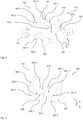
- the vehicle 101 comprises a (indicated by the contour 102) car body, which is supported in the region of both ends in a conventional manner in each case on a chassis in the form of a (not shown) bogie. It is understood, however, that the present invention may be used in conjunction with other configurations in which the body is supported only directly on a chassis.
- FIG. 1 a specified (by the Radaufstandsebene the bogie) vehicle coordinate system x, y, z, in which the x-coordinate, the vehicle longitudinal direction, the y-coordinate the vehicle transverse direction and the z-coordinate, the vehicle height direction of the rail vehicle 101.
- a buffer device in the form of side buffers 103 is arranged with a buffer longitudinal axis 103.1, which in the in FIG. 1 illustrated activated operating state of the vehicle 101 project beyond the first end 102.1 of the car body 102 in the vehicle longitudinal direction.
- the side buffers 103 are arranged at a predetermined level above the level T of the traveled track section, whereby (for example, depending on the load of the vehicle, wear of the wheel disks, etc.), a certain level difference can result.
- the page buffer 103 in the unloaded state always in the in FIG. 1 can be located. Likewise, it is also possible that they are only extended along the buffer longitudinal axes 103.1 in this position when the first end 102.1 forms the free end of the rail vehicle, while they are retracted, for example, in a coupled state to a certain extent in the car body can.
- the side buffers 103 have at an end remote from the car body 102 at least one impact element for a collision partner, which is designed in the present example in the form of a buffer plate 103.2.
- the buffer device 103 is designed in a conventional manner to absorb impacts with the impact partner under a longitudinal displacement of the buffer plate 103.2 relative to the car body 102 along the buffer longitudinal axis 103.1 or the vehicle longitudinal direction.
- a collision partner is formed in the present example by a second vehicle 104 designed identically to the first vehicle 101.
- a first return means 105 is provided, whose dimensions are chosen so that to be kept free for working in the coupling of vehicles for the executing railway workers Bernese space between the first return device 105 and the respective page buffer 103 is ensured.
- the return height HR thus corresponds to 50% of the impact element height H.
- the first return device 105 has a first return element 105.1 projecting from the vehicle body 102 in the vehicle longitudinal direction and a first return recess 105.2 offset in the vehicle transverse direction.
- the first return element 105.1 is substantially wedge-shaped in the present example and has on its upper side a first return surface 105.3, which is designed as a substantially flat surface.
- the first return surface 105.3 is inclined to both the vehicle longitudinal direction and the vehicle height direction.
- the first sudholaus originallyung 105.2 is designed, the upper wall has a second return surface 105.4, which in turn is inclined to both the vehicle longitudinal direction and to the vehicle height direction.
- the identically designed second return device 107 accordingly has a second return element 107.1 protruding in the vehicle longitudinal direction from the vehicle body 106 with a third return surface 107.3 and a second return recess 107.2 offset in the vehicle transverse direction with a fourth return surface 107.4.
- the side buffers 103 are inserted into the respective car body 102 and 106, respectively, so that the car bodies 102, 106 continue to move towards each other.
- the design described above has the advantage that hereby the initiation of a rolling torque or rolling moment (ie a moment about the vehicle longitudinal axis) in the respective car body 102 and 106 upon engagement of the retractor 105 with the with respect to the vehicle's vertical axis by 180 ° twisted, but otherwise identically designed return device 107 is avoided.
- the buffer device 103 is designed to reversibly absorb shocks that lead to a first longitudinal displacement of the respective buffer plate 103.2, which is less than a second longitudinal displacement, which in the in FIG. 2 shown second state. Accordingly, normal operation shocks, for example, when coupling the vehicle or the like, can be absorbed without damage.
- the two return devices 105 and 107 do not engage with each other in order not to hinder such normal operating shocks or to avoid the introduction of forces into the car bodies 102 and 104 via the return devices 105 and 107.
- the buffer device 103 takes over by irreversible deformation of an integrated energy dissipation element starting with the second longitudinal displacement (as in the in FIG. 2 shown second state) irreversibly impact energy. It is understood, however, that in other variants of the invention it can also be provided that a reversible absorption of the impact energy takes place beyond the second longitudinal displacement, thus the irreversible energy consumption only takes place a certain time after the return devices 105 and 107 have become effective. In this way it can be ensured that a sufficiently large return movement has already taken place by then, which ensures that the impact load is introduced into the energy-absorbing element under the most favorable conditions possible.
- a different movement of the return movement can be achieved by a corresponding design of the slope profile of the return surfaces.
- a greater inclination to the vehicle longitudinal direction at the beginning of the return movement a rapid reduction of the vertical offset can be achieved before the irreversible energy consumption begins to ensure that the impact load is introduced under the most favorable conditions in the energy absorbing element.
- the return means may be arranged in certain variants of the invention also withdrawn behind the outer shell of the car body, as shown in FIG. 1 is indicated by the dashed contour 108. In this case, then takes place before or immediately with the effectiveness of the return means deformation or damage to the outer shell of the car body instead.
- the outer shell can then be designed accordingly in order not to affect the effectiveness of the return devices.
- the retrieval device 205 may replace the retrieval device 105 in the vehicle 101.
- the return device 205 is similar in its basic function and its basic structure of the return device 105, so they should be discussed only on the differences. In particular, similar components are to be seen with reference numerals increased by 100. Unless otherwise stated below, reference is made expressly to the above statements with regard to the features and properties of these components.
- the difference between the return device 205 and the return device 105 is merely that the return device 205 has three return elements 205.1 and three return recesses 205.2.
- One of the remindholausnaturalened 205.2 is arranged between two in the vehicle height direction offset from one another arranged mulchlementen 205.1, while the offset to the two return elements 205.1 in the vehicle transverse direction third return element 205.1 is positioned between two offset in the vehicle height direction each other arranged scaffoldholausnaturalept 205.2.
- This design in turn has the advantage that hereby the introduction of a rolling torque or rolling moment (ie a moment about the vehicle longitudinal axis) in the respective car body 102 and 106 upon engagement of the return device 205 with respect to the Vehicle vertical axis rotated by 180 °, but otherwise identically designed return device 207 is avoided.
- a rolling torque or rolling moment ie a moment about the vehicle longitudinal axis
- the present invention has been described above solely by way of examples in which a height offset between the car bodies has been reduced by the retrieval device. It is understood, however, that by a suitable design of the return elements and remindholauslangungen a transverse offset can be reduced.
- the respective return device can be used rotated by 90 ° with respect to the vehicle longitudinal axis.
- both a height offset and a transverse offset can be reduced by, in addition to the above-described, inclined to the vehicle longitudinal direction and the vehicle height direction return surfaces also inclined to the vehicle longitudinal direction and the vehicle transverse direction return surfaces are provided, as shown in FIG. 5 is indicated by the dashed contour 208. It is understood that the return width, so the amount of return movement in the vehicle transverse direction, may be lower than the return height, since usually the transverse offset of the two impact partners is less than the height offset.
- the present invention can be used both on free vehicle ends and between coupled rail vehicles, as described in connection with the exemplary embodiments. Furthermore, the invention can be used both in the exemplarily described vehicles with side buffers and in vehicles with central buffer devices, for example in the form of a central buffer coupling.
- the present invention has been described above solely by means of a vehicle for multiple unit trains operating at comparatively high rated operating speeds. It is understood, however, that the invention may also be used in connection with other rail vehicles, in particular at lower or even higher rated operating speeds.
Landscapes
- Engineering & Computer Science (AREA)
- Mechanical Engineering (AREA)
- Transportation (AREA)
- Life Sciences & Earth Sciences (AREA)
- Wood Science & Technology (AREA)
- Vibration Dampers (AREA)
Claims (15)
- Véhicule ferroviaire comprenant:- une caisse de wagon (102, 106) qui définit une direction longitudinale du véhicule, une direction transversale du véhicule et une direction de la hauteur du véhicule, et- un dispositif tampon (103), dans lequel- le dispositif tampon (103) est disposé à une première extrémité de la caisse de wagon (102, 106) et, au moins dans un état de fonctionnement activé, s'étend, dans la direction longitudinale du véhicule, au-delà de la première extrémité de la caisse de wagon (102, 106),- le dispositif tampon (103) a au moins un élément d'impact (103.2) pour un partenaire de collision, localisée à l'extrémité emmenante de la caisse de wagon (102, 106) dans l'état de fonctionnement activé,- le dispositif tampon (103) est adapté pour absorber des chocs avec un partenaire de collision sous un déplacement longitudinal de l'élément d'impact (103.2) par rapport à la caisse de wagon (102, 106) dans la direction longitudinale du véhicule,- l'élément d'impact (103.2) comprend une hauteur de l'élément d'impact dans la direction de la hauteur de véhicule, et une largeur de l'élément d'impact dans la direction transversale du véhicule,caractérisé en ce que- à la première extrémité de la caisse de wagon (102, 106) au moins un dispositif de recul (105, 107; 108; 205, 207) est prévu qui est adapté pour collaborer avec un dispositif de recul complémentaire (105, 107; 108; 205, 207) sur le partenaire de collision pendant un déplacement longitudinal progressif de l'élément d'impact (103.2) pour réduire un décalage en hauteur entre la caisse de wagon (102, 106) et le partenaire de collision dans la direction de la hauteur du véhicule par une hauteur de recul, dans lequel- la hauteur de recul correspond à au moins 20% de la hauteur de l'élément d'impact, de préférence à au moins 30% de la hauteur de l'élément d'impact, plus préférablement à au moins 50% de la hauteur de l'élément d'impact.
- Véhicule ferroviaire selon la revendication 1, caractérisé en ce que- la hauteur de recul s'étend de 20% à 80% de la hauteur de l'élément d'impact, de préférence de 30% à 70% de la hauteur de l'élément d'impact, plus préférablement de 40% à 60% de la hauteur de l'élément d'impact,
et- le dispositif de recul (105, 107; 108; 205, 207) est aussi adapté pour collaborer avec un dispositif de recul complémentaire (105, 107; 108; 205, 207) sur le partenaire de collision pendant un déplacement longitudinal progressif de l'élément d'impact (103.2), pour réduire un décalage transversal entre la caisse de wagon (102, 106) et le partenaire de collision dans la direction transversale du véhicule par une largeur de recul, dans lequel la largeur de recul est au moins 20% de la largeur de l'élément d'impact, de préférence au moins 30% de la largeur de l'élément d'impact, plus préférablement au moins 50% de la largeur de l'élément d'impact, plus préférablement de 20% à 80% de la largeur de l'élément d'impact, plus préférablement de 30% à 70% de la largeur de l'élément d'impact, plus préférablement de 40% à 60% de la largeur de l'élément d'impact. - Véhicule ferroviaire selon la revendication 1 ou 2, caractérisé en ce que- la hauteur de recul et/ou la largeur de recul est de 60 mm à 220 mm, de préférence de 80 mm à 200 mm, plus préférablement de 100 mm à 180 mm, et/ou- le dispositif de recul (105, 107; 108; 205, 207) est adaptée pour réduire, lors de l'engagement complet avec le dispositif de recul complémentaire (105, 107; 108; 205, 207), le décalage en hauteur et/ou le décalage transversal entre la caisse de wagon (102, 106) et le partenaire de collision à une valeur inférieure à 80 mm, de préférence inférieure à 40 mm, plus préférablement à sensiblement 0 mm.
- Véhicule ferroviaire selon l'une quelconque des revendications précédentes, caractérisé en ce que- le dispositif de recul (105, 107; 108; 205, 207) a au moins un élément de recul (105.1, 107.1 ; 205.1, 207.1) saillant dans la direction longitudinale du véhicule,
dans lequel- l'élément de recul (105.1, 107.1 ; 205.1, 207.1) est adapté pour coopérer avec le dispositif de recul complémentaire (105, 107; 108; 205, 207), en particulier une paroi d'une cavité de recul complémentaire (105.2, 107.2; 205.2, 207.2) du dispositif de recul complémentaire (105, 107; 108; 205, 207), pour réduire le décalage transversal et/ou le décalage en hauteur, et
dans lequel- l'élément de recul (105.1, 107.1; 205.1, 207.1), en particulier, fait saillie de la caisse de wagon (102, 106), et/ou le dispositif de recul (108), en particulier, est disposé au moins en partie, de préférence pratiquement totalement, rétractée derrière un contour extérieur de la caisse de wagon (102, 106). - Véhicule ferroviaire selon la revendication 4, caractérisé en ce que- l'élément de recul (105.1, 107.1; 205.1, 207.1) et/ou la paroi de la cavité de recul (105.2, 107.2; 205.2, 207.2) a au moins une surface de recul (105.3, 105.4, 107.3, 107.4) inclinée par rapport à la direction longitudinale du véhicule, dans lequel- la surface de recul (105.3, 105.4, 107.3, 107.4) est formée en particulier comme une surface sensiblement plane
et/ou- l'élément de recul (105.1, 107.1; 205.1, 207.1) et/ou la cavité de recul (105.2, 107.2; 205.2, 207.2) est formée en particulier sensiblement en forme de coin ou sensiblement en forme de pyramide. - Véhicule ferroviaire selon la revendication 5, caractérisé en ce que- l'élément de recul (105.1, 107.1; 205.1, 207.1) et/ou la paroi de la cavité de recul (105.2, 107.2; 205.2, 207.2), a au moins une surface de recul en hauteur (105.3, 105.4, 107.3, 107.4), et/ou au moins une surface de recul transversale, dans lequel- la surface de recul en hauteur (105.3, 105.4, 107.3, 107.4) se prolonge, dans la direction de la hauteur de véhicule, au moins sur la hauteur de recul
et/ou- la surface de recul transversale se prolonge, dans la direction transversale du véhicule, au moins sur la largeur de recul. - Véhicule ferroviaire selon l'une quelconque des revendications 4 à 6, caractérisé en ce que- le dispositif de recul (205, 207) a au moins deux éléments de recul (205.1, 207.1), dans lequel- les au moins deux éléments de recul (205.1, 207.1) sont disposées de manière décalée les uns aux autres dans la direction de la hauteur du véhicule et/ou dans la direction transversale du véhicule.
- Véhicule ferroviaire selon l'une quelconque des revendications précédentes, caractérisé en ce que- le dispositif de recul (105, 107; 108; 205, 207) a au moins une cavité de recul (105.2, 107.2; 205.2, 207.2) s'étendant dans la direction longitudinale du véhicule, dans lequel- au moins une paroi de la cavité de recul (105.2, 107.2; 205.2, 207.2) est adaptée pour coopérer avec le dispositif de recul complémentaire (105, 107; 108; 205, 207), en particulier un élément de recul complémentaire (105.1, 107.1, 205.1, 207.1) du dispositif de recul complémentaire (105, 107; 108; 205, 207), pour réduire le décalage transversal et/ou le décalage en hauteur.
- Véhicule ferroviaire selon la revendication 8, caractérisé en ce que- le dispositif de recul (205, 207) a au moins deux cavités de recul (205.2, 207.2), dans lequel- les au moins deux cavités de recul (205.2, 207.2) sont disposées de manière décalée les uns aux autres dans la direction de la hauteur du véhicule et/ou dans la direction transversale du véhicule.
- Véhicule ferroviaire selon l'une quelconque des revendications précédentes, caractérisé en ce que- le dispositif de recul (105, 107; 108; 205, 207) est adapté pour limiter, sensiblement immédiatement au début du contact avec le dispositif de recul complémentaire (105, 107; 108; 205, 207), le décalage en hauteur entre la caisse de wagon (102, 106) et le partenaire de collision dans la direction de la hauteur du véhicule et/ou le décalage transversal entre la caisse de wagon (102, 106) et le partenaire de collision dans la direction transversale du véhicule,
et/ou- le dispositif de recul (105, 107; 108; 205, 207) est adapté pour réduire, sensiblement immédiatement au début du contact avec le dispositif de recul complémentaire (105, 107; 108; 205, 207), le décalage en hauteur entre la caisse de wagon (102, 106) et le partenaire de collision dans la direction de la hauteur du véhicule et/ou le décalage transversal entre la caisse de wagon (102, 106) et le partenaire de collision dans la direction transversale du véhicule. - Véhicule ferroviaire selon l'une quelconque des revendications précédentes, caractérisé en ce que- le dispositif tampon (103) est adapté pour recevoir de manière réversible des chocs avec un partenaire de collision jusqu'à un premier déplacement longitudinal de l'élément d'impact (103.2) par rapport la caisse de wagon (102, 106) dans la direction longitudinale du véhicule, et- le dispositif de recul (105, 107; 205, 207; 108), en particulier, est arrangé et construit de telle sorte que, en cas de collision entre la caisse de wagon (102, 106) et le partenaire de collision, il ne vient pas en prise avec le dispositif de recul complémentaire (105, 107; 108; 205, 207) du partenaire de collision jusqu'au premier déplacement longitudinal de l'élément d'impact (103.2), dans lequel- le dispositif de recul (105, 107; 205, 207; 108) est en particulier arrangé et construit de telle sorte que, en cas de collision entre la caisse de wagon (102, 106) et le partenaire de collision, il vient en prise avec le dispositif de recul complémentaire (105, 107; 108; 205, 207) du partenaire de collision à partir d'un second déplacement longitudinal de l'élément d'impact (103.2), dans lequel le dispositif tampon (103) sensiblement absorbe réversiblement le choc jusqu'au second déplacement longitudinal, dans lequel- le dispositif tampon (103) et/ou le dispositif de recul (105, 107; 108; 205, 207), en particulier, est adapté pour absorber des collisions avec un partenaire de collision à partir du deuxième déplacement longitudinal de l'élément d'impact (103.2) par rapport à la caisse de wagon (102, 106) dans la direction longitudinale du véhicule par une déformation irréversible d'au moins un élément absorbeur d'énergie.
- Véhicule ferroviaire selon l'une quelconque des revendications précédentes, caractérisé en ce que le dispositif tampon (103) et le dispositif de recul (105, 107; 108; 205, 207) sont disposés à une extrémité libre (102.1) de la caisse de wagon (102) et/ou à une extrémité couplée de la caisse de wagon.
- Véhicule ferroviaire selon l'une quelconque des revendications précédentes, caractérisé en ce que le dispositif de recul (105, 107; 108; 205, 207) est disposé de manière centrale en direction transversale du véhicule sur la caisse de wagon (102, 106).
- Véhicule ferroviaire selon l'une quelconque des revendications précédentes, caractérisé en ce que le dispositif tampon (103) est formé comme un dispositif tampon latéral (103) ou comme un dispositif tampon central.
- Dispositif de recul pour un véhicule ferroviaire selon l'une quelconque des revendications précédentes, comprenant une caisse de wagon (102, 106) et un dispositif tampon (103), dans lequel la caisse de wagon (102, 106) définit une direction longitudinale du véhicule, une direction transversale du véhicule et une direction de la hauteur du véhicule, le dispositif tampon (103) est disposé à une première extrémité de la caisse de wagon (102, 106) et, dans au moins un état de fonctionnement activé, s'étend, dans la direction longitudinale du véhicule, au-delà de la première extrémité de la caisse de wagon (102, 106), le dispositif tampon (103) est adapté pour recevoir, à l'extrémité emmenante de la caisse de wagon (102, 106) dans l'état de fonctionnement activé, au moins un élément d'impact (103.2) pour un partenaire de collision et le dispositif tampon (103) est adapté pour absorber les chocs à un partenaire de collision sous un déplacement longitudinal de l'élément d'impact (103.2) par rapport à la caisse de wagon (102, 106) dans la direction longitudinale du véhicule, dans lequel- l'élément d'impact (103.2) a une hauteur de l'élément d'impact dans la direction de la hauteur de véhicule, et une largeur de l'élément d'impact dans la direction transversale du véhicule, dans lequel- le dispositif de recul (105, 107; 205, 207; 108) est adapté pour être disposé à la première extrémité de la caisse de wagon (102, 106),caractérisé en ce que- le dispositif de recul (105, 107; 205, 207; 108) est adapté pour collaborer, pendant un déplacement longitudinal progressif de l'élément d'impact (103.2), avec un dispositif de recul complémentaire (105, 107; 108; 205, 207) sur le partenaire de collision pour réduire un décalage en hauteur entre la caisse de wagon (102, 106) et le partenaire de collision dans la direction de la hauteur du véhicule par une hauteur de recul, dans lequel- la hauteur de recul correspond à au moins 20% de la hauteur de l'élément d'impact, de préférence à au moins 30% de la hauteur de l'élément d'impact, plus préférablement à au moins 50% de la hauteur de l'élément d'impact.
Applications Claiming Priority (2)
| Application Number | Priority Date | Filing Date | Title |
|---|---|---|---|
| DE102011013956 | 2011-03-14 | ||
| DE102011014631A DE102011014631A1 (de) | 2011-03-14 | 2011-03-21 | Schienenfahrzeug mit einer Rückholeinrichtung zur Reduzierung des Versatzes zu einem Crashpartner |
Publications (2)
| Publication Number | Publication Date |
|---|---|
| EP2500228A1 EP2500228A1 (fr) | 2012-09-19 |
| EP2500228B1 true EP2500228B1 (fr) | 2017-07-19 |
Family
ID=45894178
Family Applications (1)
| Application Number | Title | Priority Date | Filing Date |
|---|---|---|---|
| EP12159411.3A Active EP2500228B1 (fr) | 2011-03-14 | 2012-03-14 | Véhicule ferroviaire doté d'un moyen de rappel pour la réduction du déplacement contre un partenaire de collision |
Country Status (2)
| Country | Link |
|---|---|
| EP (1) | EP2500228B1 (fr) |
| DE (1) | DE102011014631A1 (fr) |
Families Citing this family (2)
| Publication number | Priority date | Publication date | Assignee | Title |
|---|---|---|---|---|
| DE102014113422A1 (de) | 2014-09-17 | 2016-03-17 | Bombardier Transportation Gmbh | Schienenfahrzeug mit einer Befestigungsanordnung für ein Anbauteil und Verfahren zum Befestigen eines Anbauteils an einem Wagenkasten eines Schienenfahrzeugs |
| CN106956686A (zh) * | 2017-04-27 | 2017-07-18 | 西南交通大学 | 一种轨道车辆自对中防爬防偏装置 |
Family Cites Families (5)
| Publication number | Priority date | Publication date | Assignee | Title |
|---|---|---|---|---|
| DE4332289A1 (de) * | 1993-09-20 | 1995-03-23 | Deutsche Bahn Ag | Vorrichtung zum Verhindern des Aufkletterns von Schienenfahrzeugen als Folge eines unfallbedingten Aufpralls |
| DE20117536U1 (de) | 2001-10-26 | 2002-01-10 | Siemens Duewag Schienenfahrzeuge GmbH, 47829 Krefeld | Kletterschutzvorrichtung für Schienenfahrzeuge mit Seitenpuffern |
| AT413683B (de) * | 2003-06-13 | 2006-05-15 | Siemens Sgp Verkehrstech Gmbh | Aufkletterschutz für schienenfahrzeuge |
| DE102007005421A1 (de) | 2007-01-30 | 2008-08-07 | Bombardier Transportation Gmbh | Stoßenergieverzehrelement für ein Fahrzeug |
| DE102008048244B8 (de) * | 2008-09-16 | 2010-02-11 | Vossloh Locomotives Gmbh | Aufkletterschutz für Puffer an Lokomotiven |
-
2011
- 2011-03-21 DE DE102011014631A patent/DE102011014631A1/de not_active Withdrawn
-
2012
- 2012-03-14 EP EP12159411.3A patent/EP2500228B1/fr active Active
Also Published As
| Publication number | Publication date |
|---|---|
| EP2500228A1 (fr) | 2012-09-19 |
| DE102011014631A1 (de) | 2012-09-20 |
Similar Documents
| Publication | Publication Date | Title |
|---|---|---|
| EP2594452B1 (fr) | Dispositif d'embrayage pour la zone frontale d'un véhicule guidé sur rails | |
| DE69706597T2 (de) | Schienenfahrzeug mit einem Fahrerstand, der eine energieaufnehmende Struktur mit progressiver Verformung aufweist | |
| EP1791747B1 (fr) | Element deformable comprenant un mecanisme de guidage | |
| EP2183145B1 (fr) | Dispositif antichoc pour la zone avant ou arrière d'un véhicule guidé sur rails, comportant au moins un dispositif d'absorption d'énergie | |
| EP1900593B1 (fr) | Véhicule sur rails doté d'un équipement anti-collision | |
| CH658631A5 (de) | Schienenfahrzeug mit mittelpufferkupplung. | |
| WO2008135414A2 (fr) | Dispositif d'absorption d'énergie pour véhicules en unités multiples | |
| EP2277762B1 (fr) | Véhicule ferroviaire doté d'un absorbeur 'énergie, notamment pour un tramway | |
| EP2999609B1 (fr) | Véhicule ferroviaire à système d'attelage entrant entièrement dans la structure | |
| AT510958B1 (de) | Anordnung zur umlenkung einer durch das versagen einer überlastsicherung im zuge eines zusammenstosses abgetrennten mittelpufferkupplung eines schienenfahrzeugs | |
| EP3530544B1 (fr) | Dispositif de déformation pourvu de protection anti-chevauchement pour véhicules ferroviaires | |
| AT413683B (de) | Aufkletterschutz für schienenfahrzeuge | |
| EP2500228B1 (fr) | Véhicule ferroviaire doté d'un moyen de rappel pour la réduction du déplacement contre un partenaire de collision | |
| EP2920041B1 (fr) | Protection anti-montee | |
| EP3640113A1 (fr) | Dispositif de réception de l'énergie et véhicule ferroviaire | |
| DE102006050028B4 (de) | Vorrichtung an der Fahrzeugfront von Schienenfahrzeugen | |
| DE102013009121B3 (de) | Überpufferungsschutz für Schienenfahrzeuge | |
| AT511290A1 (de) | Schienenfahrzeug mit verformungszone | |
| EP1306281B1 (fr) | Dispositif d'anti-chevauchement pour véhicules ferroviaires avec tampons latéraux | |
| DE941913C (de) | Zug- und Stossvorrichtung fuer Schienenfahrzeuge mit Mittelpufferkupplung | |
| DE112013002238B4 (de) | Eisenbahnwagenkarosseriestruktur mit Stoßdämpfungsstruktur | |
| EP3771609B1 (fr) | Tampon plongeur pourvu de poussoir enrobé par de section | |
| DE102018130253A1 (de) | Crashpuffer mit führungsstange, tragstruktur und schienenfahrzeug | |
| EP1866194B1 (fr) | Vehicule sur rails comportant un systeme d'attelage resistant aux collisions | |
| EP2544939B1 (fr) | Dispositif destiné à limiter un mouvement de tangage de véhicules ferroviaires |
Legal Events
| Date | Code | Title | Description |
|---|---|---|---|
| PUAI | Public reference made under article 153(3) epc to a published international application that has entered the european phase |
Free format text: ORIGINAL CODE: 0009012 |
|
| AK | Designated contracting states |
Kind code of ref document: A1 Designated state(s): AL AT BE BG CH CY CZ DE DK EE ES FI FR GB GR HR HU IE IS IT LI LT LU LV MC MK MT NL NO PL PT RO RS SE SI SK SM TR |
|
| AX | Request for extension of the european patent |
Extension state: BA ME |
|
| 17P | Request for examination filed |
Effective date: 20130319 |
|
| 17Q | First examination report despatched |
Effective date: 20141218 |
|
| GRAP | Despatch of communication of intention to grant a patent |
Free format text: ORIGINAL CODE: EPIDOSNIGR1 |
|
| INTG | Intention to grant announced |
Effective date: 20170201 |
|
| GRAS | Grant fee paid |
Free format text: ORIGINAL CODE: EPIDOSNIGR3 |
|
| GRAA | (expected) grant |
Free format text: ORIGINAL CODE: 0009210 |
|
| AK | Designated contracting states |
Kind code of ref document: B1 Designated state(s): AL AT BE BG CH CY CZ DE DK EE ES FI FR GB GR HR HU IE IS IT LI LT LU LV MC MK MT NL NO PL PT RO RS SE SI SK SM TR |
|
| REG | Reference to a national code |
Ref country code: GB Ref legal event code: FG4D Free format text: NOT ENGLISH |
|
| REG | Reference to a national code |
Ref country code: CH Ref legal event code: EP |
|
| REG | Reference to a national code |
Ref country code: IE Ref legal event code: FG4D Free format text: LANGUAGE OF EP DOCUMENT: GERMAN |
|
| REG | Reference to a national code |
Ref country code: AT Ref legal event code: REF Ref document number: 910080 Country of ref document: AT Kind code of ref document: T Effective date: 20170815 |
|
| REG | Reference to a national code |
Ref country code: DE Ref legal event code: R096 Ref document number: 502012010784 Country of ref document: DE |
|
| RAP2 | Party data changed (patent owner data changed or rights of a patent transferred) |
Owner name: BOMBARDIER TRANSPORTATION GMBH |
|
| REG | Reference to a national code |
Ref country code: CH Ref legal event code: NV Representative=s name: TROESCH SCHEIDEGGER WERNER AG, CH |
|
| REG | Reference to a national code |
Ref country code: NL Ref legal event code: MP Effective date: 20170719 |
|
| REG | Reference to a national code |
Ref country code: LT Ref legal event code: MG4D |
|
| PG25 | Lapsed in a contracting state [announced via postgrant information from national office to epo] |
Ref country code: SE Free format text: LAPSE BECAUSE OF FAILURE TO SUBMIT A TRANSLATION OF THE DESCRIPTION OR TO PAY THE FEE WITHIN THE PRESCRIBED TIME-LIMIT Effective date: 20170719 Ref country code: LT Free format text: LAPSE BECAUSE OF FAILURE TO SUBMIT A TRANSLATION OF THE DESCRIPTION OR TO PAY THE FEE WITHIN THE PRESCRIBED TIME-LIMIT Effective date: 20170719 Ref country code: FI Free format text: LAPSE BECAUSE OF FAILURE TO SUBMIT A TRANSLATION OF THE DESCRIPTION OR TO PAY THE FEE WITHIN THE PRESCRIBED TIME-LIMIT Effective date: 20170719 Ref country code: HR Free format text: LAPSE BECAUSE OF FAILURE TO SUBMIT A TRANSLATION OF THE DESCRIPTION OR TO PAY THE FEE WITHIN THE PRESCRIBED TIME-LIMIT Effective date: 20170719 Ref country code: NL Free format text: LAPSE BECAUSE OF FAILURE TO SUBMIT A TRANSLATION OF THE DESCRIPTION OR TO PAY THE FEE WITHIN THE PRESCRIBED TIME-LIMIT Effective date: 20170719 Ref country code: NO Free format text: LAPSE BECAUSE OF FAILURE TO SUBMIT A TRANSLATION OF THE DESCRIPTION OR TO PAY THE FEE WITHIN THE PRESCRIBED TIME-LIMIT Effective date: 20171019 |
|
| PG25 | Lapsed in a contracting state [announced via postgrant information from national office to epo] |
Ref country code: PL Free format text: LAPSE BECAUSE OF FAILURE TO SUBMIT A TRANSLATION OF THE DESCRIPTION OR TO PAY THE FEE WITHIN THE PRESCRIBED TIME-LIMIT Effective date: 20170719 Ref country code: ES Free format text: LAPSE BECAUSE OF FAILURE TO SUBMIT A TRANSLATION OF THE DESCRIPTION OR TO PAY THE FEE WITHIN THE PRESCRIBED TIME-LIMIT Effective date: 20170719 Ref country code: IS Free format text: LAPSE BECAUSE OF FAILURE TO SUBMIT A TRANSLATION OF THE DESCRIPTION OR TO PAY THE FEE WITHIN THE PRESCRIBED TIME-LIMIT Effective date: 20171119 Ref country code: LV Free format text: LAPSE BECAUSE OF FAILURE TO SUBMIT A TRANSLATION OF THE DESCRIPTION OR TO PAY THE FEE WITHIN THE PRESCRIBED TIME-LIMIT Effective date: 20170719 Ref country code: BG Free format text: LAPSE BECAUSE OF FAILURE TO SUBMIT A TRANSLATION OF THE DESCRIPTION OR TO PAY THE FEE WITHIN THE PRESCRIBED TIME-LIMIT Effective date: 20171019 Ref country code: RS Free format text: LAPSE BECAUSE OF FAILURE TO SUBMIT A TRANSLATION OF THE DESCRIPTION OR TO PAY THE FEE WITHIN THE PRESCRIBED TIME-LIMIT Effective date: 20170719 Ref country code: GR Free format text: LAPSE BECAUSE OF FAILURE TO SUBMIT A TRANSLATION OF THE DESCRIPTION OR TO PAY THE FEE WITHIN THE PRESCRIBED TIME-LIMIT Effective date: 20171020 |
|
| REG | Reference to a national code |
Ref country code: FR Ref legal event code: PLFP Year of fee payment: 7 |
|
| REG | Reference to a national code |
Ref country code: DE Ref legal event code: R097 Ref document number: 502012010784 Country of ref document: DE |
|
| PG25 | Lapsed in a contracting state [announced via postgrant information from national office to epo] |
Ref country code: DK Free format text: LAPSE BECAUSE OF FAILURE TO SUBMIT A TRANSLATION OF THE DESCRIPTION OR TO PAY THE FEE WITHIN THE PRESCRIBED TIME-LIMIT Effective date: 20170719 Ref country code: CZ Free format text: LAPSE BECAUSE OF FAILURE TO SUBMIT A TRANSLATION OF THE DESCRIPTION OR TO PAY THE FEE WITHIN THE PRESCRIBED TIME-LIMIT Effective date: 20170719 Ref country code: RO Free format text: LAPSE BECAUSE OF FAILURE TO SUBMIT A TRANSLATION OF THE DESCRIPTION OR TO PAY THE FEE WITHIN THE PRESCRIBED TIME-LIMIT Effective date: 20170719 |
|
| PLBE | No opposition filed within time limit |
Free format text: ORIGINAL CODE: 0009261 |
|
| STAA | Information on the status of an ep patent application or granted ep patent |
Free format text: STATUS: NO OPPOSITION FILED WITHIN TIME LIMIT |
|
| PG25 | Lapsed in a contracting state [announced via postgrant information from national office to epo] |
Ref country code: EE Free format text: LAPSE BECAUSE OF FAILURE TO SUBMIT A TRANSLATION OF THE DESCRIPTION OR TO PAY THE FEE WITHIN THE PRESCRIBED TIME-LIMIT Effective date: 20170719 Ref country code: IT Free format text: LAPSE BECAUSE OF FAILURE TO SUBMIT A TRANSLATION OF THE DESCRIPTION OR TO PAY THE FEE WITHIN THE PRESCRIBED TIME-LIMIT Effective date: 20170719 Ref country code: SM Free format text: LAPSE BECAUSE OF FAILURE TO SUBMIT A TRANSLATION OF THE DESCRIPTION OR TO PAY THE FEE WITHIN THE PRESCRIBED TIME-LIMIT Effective date: 20170719 Ref country code: SK Free format text: LAPSE BECAUSE OF FAILURE TO SUBMIT A TRANSLATION OF THE DESCRIPTION OR TO PAY THE FEE WITHIN THE PRESCRIBED TIME-LIMIT Effective date: 20170719 |
|
| 26N | No opposition filed |
Effective date: 20180420 |
|
| PG25 | Lapsed in a contracting state [announced via postgrant information from national office to epo] |
Ref country code: SI Free format text: LAPSE BECAUSE OF FAILURE TO SUBMIT A TRANSLATION OF THE DESCRIPTION OR TO PAY THE FEE WITHIN THE PRESCRIBED TIME-LIMIT Effective date: 20170719 |
|
| PG25 | Lapsed in a contracting state [announced via postgrant information from national office to epo] |
Ref country code: MT Free format text: LAPSE BECAUSE OF FAILURE TO SUBMIT A TRANSLATION OF THE DESCRIPTION OR TO PAY THE FEE WITHIN THE PRESCRIBED TIME-LIMIT Effective date: 20170719 |
|
| GBPC | Gb: european patent ceased through non-payment of renewal fee |
Effective date: 20180314 |
|
| PG25 | Lapsed in a contracting state [announced via postgrant information from national office to epo] |
Ref country code: MC Free format text: LAPSE BECAUSE OF FAILURE TO SUBMIT A TRANSLATION OF THE DESCRIPTION OR TO PAY THE FEE WITHIN THE PRESCRIBED TIME-LIMIT Effective date: 20170719 |
|
| REG | Reference to a national code |
Ref country code: BE Ref legal event code: MM Effective date: 20180331 |
|
| REG | Reference to a national code |
Ref country code: IE Ref legal event code: MM4A |
|
| PG25 | Lapsed in a contracting state [announced via postgrant information from national office to epo] |
Ref country code: LU Free format text: LAPSE BECAUSE OF NON-PAYMENT OF DUE FEES Effective date: 20180314 |
|
| PG25 | Lapsed in a contracting state [announced via postgrant information from national office to epo] |
Ref country code: IE Free format text: LAPSE BECAUSE OF NON-PAYMENT OF DUE FEES Effective date: 20180314 |
|
| PG25 | Lapsed in a contracting state [announced via postgrant information from national office to epo] |
Ref country code: BE Free format text: LAPSE BECAUSE OF NON-PAYMENT OF DUE FEES Effective date: 20180331 Ref country code: GB Free format text: LAPSE BECAUSE OF NON-PAYMENT OF DUE FEES Effective date: 20180314 |
|
| PG25 | Lapsed in a contracting state [announced via postgrant information from national office to epo] |
Ref country code: TR Free format text: LAPSE BECAUSE OF FAILURE TO SUBMIT A TRANSLATION OF THE DESCRIPTION OR TO PAY THE FEE WITHIN THE PRESCRIBED TIME-LIMIT Effective date: 20170719 |
|
| PG25 | Lapsed in a contracting state [announced via postgrant information from national office to epo] |
Ref country code: PT Free format text: LAPSE BECAUSE OF FAILURE TO SUBMIT A TRANSLATION OF THE DESCRIPTION OR TO PAY THE FEE WITHIN THE PRESCRIBED TIME-LIMIT Effective date: 20170719 Ref country code: HU Free format text: LAPSE BECAUSE OF FAILURE TO SUBMIT A TRANSLATION OF THE DESCRIPTION OR TO PAY THE FEE WITHIN THE PRESCRIBED TIME-LIMIT; INVALID AB INITIO Effective date: 20120314 |
|
| PG25 | Lapsed in a contracting state [announced via postgrant information from national office to epo] |
Ref country code: MK Free format text: LAPSE BECAUSE OF NON-PAYMENT OF DUE FEES Effective date: 20170719 Ref country code: CY Free format text: LAPSE BECAUSE OF FAILURE TO SUBMIT A TRANSLATION OF THE DESCRIPTION OR TO PAY THE FEE WITHIN THE PRESCRIBED TIME-LIMIT Effective date: 20170719 |
|
| PG25 | Lapsed in a contracting state [announced via postgrant information from national office to epo] |
Ref country code: AL Free format text: LAPSE BECAUSE OF FAILURE TO SUBMIT A TRANSLATION OF THE DESCRIPTION OR TO PAY THE FEE WITHIN THE PRESCRIBED TIME-LIMIT Effective date: 20170719 |
|
| PGFP | Annual fee paid to national office [announced via postgrant information from national office to epo] |
Ref country code: DE Payment date: 20220322 Year of fee payment: 11 Ref country code: CH Payment date: 20220321 Year of fee payment: 11 |
|
| P01 | Opt-out of the competence of the unified patent court (upc) registered |
Effective date: 20230822 |
|
| REG | Reference to a national code |
Ref country code: DE Ref legal event code: R119 Ref document number: 502012010784 Country of ref document: DE |
|
| REG | Reference to a national code |
Ref country code: CH Ref legal event code: PL |
|
| PG25 | Lapsed in a contracting state [announced via postgrant information from national office to epo] |
Ref country code: LI Free format text: LAPSE BECAUSE OF NON-PAYMENT OF DUE FEES Effective date: 20230331 Ref country code: DE Free format text: LAPSE BECAUSE OF NON-PAYMENT OF DUE FEES Effective date: 20231003 Ref country code: CH Free format text: LAPSE BECAUSE OF NON-PAYMENT OF DUE FEES Effective date: 20230331 |
|
| PGFP | Annual fee paid to national office [announced via postgrant information from national office to epo] |
Ref country code: AT Payment date: 20240321 Year of fee payment: 13 |
|
| REG | Reference to a national code |
Ref country code: AT Ref legal event code: MM01 Ref document number: 910080 Country of ref document: AT Kind code of ref document: T Effective date: 20250314 |
|
| PG25 | Lapsed in a contracting state [announced via postgrant information from national office to epo] |
Ref country code: AT Free format text: LAPSE BECAUSE OF NON-PAYMENT OF DUE FEES Effective date: 20250314 |
|
| PGFP | Annual fee paid to national office [announced via postgrant information from national office to epo] |
Ref country code: FR Payment date: 20260320 Year of fee payment: 15 |