EP2500244B1 - Système de support d'un panneau latéral aérodynamique d'un kit aérodynamique d'une cabine d'un véhicule industriel - Google Patents
Système de support d'un panneau latéral aérodynamique d'un kit aérodynamique d'une cabine d'un véhicule industriel Download PDFInfo
- Publication number
- EP2500244B1 EP2500244B1 EP20110158410 EP11158410A EP2500244B1 EP 2500244 B1 EP2500244 B1 EP 2500244B1 EP 20110158410 EP20110158410 EP 20110158410 EP 11158410 A EP11158410 A EP 11158410A EP 2500244 B1 EP2500244 B1 EP 2500244B1
- Authority
- EP
- European Patent Office
- Prior art keywords
- cabin
- aerodynamic
- hinges
- panel
- support system
- Prior art date
- Legal status (The legal status is an assumption and is not a legal conclusion. Google has not performed a legal analysis and makes no representation as to the accuracy of the status listed.)
- Active
Links
Images

Classifications
-
- B—PERFORMING OPERATIONS; TRANSPORTING
- B62—LAND VEHICLES FOR TRAVELLING OTHERWISE THAN ON RAILS
- B62D—MOTOR VEHICLES; TRAILERS
- B62D35/00—Vehicle bodies characterised by streamlining
- B62D35/001—For commercial vehicles or tractor-trailer combinations, e.g. caravans
Definitions
- the present invention refers to a support system of a lateral aerodynamic panel of an aerodynamic kit of a cabin of an industrial vehicle.
- Industrial vehicles above all those having a tractor and a semitrailer, usually comprise an aerodynamic kit associated to the cabin, whose aim is to reduce vehicle's wind resistance. Since the cabin defines a lower front surface with respect to the semitrailer, a spoiler is placed on the roof of the cabin in order to suitably connect the front surfaces of the two vehicle's portions and a pair of aerodynamic panels are laterally arranged between the cabin and the semitrailer, in order to obtain a continuous aerodynamic surface between the cabin and the semitrailer.
- Such lateral panels are fixed to the cabin.
- one panel is fixed, while the other may at least partially oscillate, so that the driver can easily reach the devices placed behind the cabin when the semitrailer is attached to the tractor.
- the aerodynamic panel opens towards the outside of the vehicle, while according to another solution the panel can be closed inside the vehicle, by folding over the rear surface of the cabin.
- Having a fixed portion of the panel implies that the width of the driver's access to the rear part of the cabin is reduced, when the semitrailer is attached to the tractor.
- the aim of the present invention is to overcome all the drawbacks set forth above and to provide a support system of a lateral aerodynamic panel of an aerodynamic kit of a cabin of an industrial vehicle suitable to adapt to any rear profile of the cabin, so that it can be monolithic and it can fully clear the lateral access to the rear part of the cabin when the semitrailer is attached to the tractor.
- the object of the present invention is a support system of a lateral aerodynamic panel of an aerodynamic kit of a cabin of an industrial vehicle suitable to adapt to any rear profile of the cabin, according to claim 1.
- the object of the present invention is in particular a lateral aerodynamic panel of an aerodynamic kit of a cabin of an industrial vehicle, comprising said support system suitable to adapt to any rear profile of the cabin, as described more fully in the claims which are an integral part of the present description.
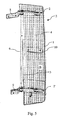
- the present invention comprises an aerodynamic panel 1, having a vertical development, fixed to a cabin C of a vehicle by means of a support device comprising at least two parallelogram hinges 2 and 2', also called two-axis hinges.
- Each hinge comprises a fixing bracket 21 to the cabin C of the vehicle and a fixing bracket 22 to the aerodynamic panel 1.
- the two brackets 21 and 22 have a U-shaped cross section.
- Each bracket comprises two seats for the respective fixing pins of the ends of two connecting rods 23 and 24.
- each connecting rod 23 and 24 has a first end rotatably associated to the fixing bracket 21 and a second end rotatably associated to the fixing bracket 22.
- the connecting rod 24 is internal to the hinge's range of movement, since it is always comprised between the aerodynamic panel 1 and the connecting rod 23, which is thus external to the range.
- the connecting rods' axis of rotation are reciprocally parallel.
- the connecting rods are fixed in such a way that they cannot cross.
- the two connecting rods lie on the same opening plane as the hinge.
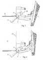
- Figure 1 shows the aerodynamic panel arranged in running conditions, namely aligned to the profile of the lateral wall of the vehicle cabin.
- the aerodynamic panel thanks to the two-axis hinges, moves away from such alignment with the lateral wall of the cabin C and ends its opening by overlapping on the lateral wall C1 of the cabin.
- the movement of the system and therefore the reciprocal positioning of the hinges is such that the opening/closing movement of the aerodynamic panel is substantially parallel to itself.
- hinge 2 is above the hinge 2', preferably plumb with respect to the latter.
- the face 1a of the panel always faces the outside, thus it is not necessary to take care of the appearance of the internal face 1b, moreover it is possible to completely remove the panel, thus completely clearing the lateral access to the devices of the rear part of the cabin when the semitrailer is attached to the tractor.
- the fixing bracket 21 of the upper hinge 2 may comprise an extension 8 and 9 respectively in order to adapt to the shape of the rear surface of the cabin.
- first stiffening rod 3 is connected by a first end to the connecting rod 24 comprised in the upper hinge 2 and by a second end to the connecting rod 24 comprised in the lower hinge 2', so that it is perpendicular to the opening planes of the hinges, which are reciprocally parallel.
- a second stiffening rod 4 is connected by a first end to the bracket 22 of the upper hinge 2 and by a second end to the bracket 22 of the lower hinge 2', so that it is substantially parallel to the vertical development of the aerodynamic panel 1.
- the panel may be made of any material, for example plastic, fiberglass, carbon fiber, etc.
- the stiffening rod 4 allows to anchor the panel to the support device not only in correspondence of the hinges, but also in an intermediate area between the hinges, since it is possible to exploit the second stiffening rod 4 that is parallel to the aerodynamic panel 1.
- at least a further interconnection between the aerodynamic panel 1 and the support system is possible.
- the support system in an alternative preferred embodiment, thus comprises at least two hinges and the interconnection rods 3 and 4 and at least a further interconnection element 10 that is intermediate between the two hinges 2 and 2' fixed to said stiffening rod 4.
- At least one of the two hinges comprises limit stops both for opening and for closing. Both are preferably adjustable.
- a first limit stop includes a pad 42, for example an elastomeric pad, fixed to the internal connected rod 24 by a screw, a nut and a lock nut, so that it projects with respect to the connecting rod and it abuts against the bracket 22, when the panel is in a position fully closed.
- a pad 42 for example an elastomeric pad
- the bracket 22 is provided with a tongue 32 suitable to abut against the pad 42.
- Another pad 26 is integral with the bracket 22, showed in figures 1 - 4 and 6 , and is intended to abut against the connecting rod 24 when the panel is in a fully open position.
- the pad may positioned either on a fixing bracket or on a connecting rod without distinction. It is evident that inverting the reciprocal position tongue/pad is completely equivalent, even though the configuration showed is preferable in terms of bulk.
- At least one of the two hinges comprises a closing lock of the aerodynamic panel, which prevents its opening when the vehicle is travelling.
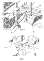
- the lower hinge 2' with particular reference to figures 6 and 7 comprises a latch 5, enbloc with a handle 52, slidingly fixed to the fixing bracket 22 of the aerodynamic panel 1.
- the latch 5 is placed and may slide perpendicularly to the opening plane of the hinge.
- the internal connecting rod 24 has a slot 33 in correspondence of the coupling end 51 of the latch 5.
- the coupling end 51 of the latch 5 engages the slot 33 of the internal connecting rod 24, thus preventing the opening of the hinge.
- a return spring not showed in the figures, forces the latch to engage said slot.
- the handle 52 of the latch is dimensioned so that the driver can grab it by slipping a hand under the lower edge of the aerodynamic panel 1, so that he/she can pull it down in order to unlock the corresponding lower hinge 2'.
- the side of the coupling end 51 of the latch 5 that faces the slot 33 is rounded, when it is not engaged with it, and its opposite side is flat, while the internal connecting rod 24 comprises a guiding tongue 44 which cooperates with the rounding of the end 51 in order to induce the lowering of the latch during the locking of the aerodynamic panel 1. Then, when the end 51 reaches the slot 33, the return spring makes the latch raise and engage the slot 33.
- each connecting rod is realized by means of a pair of flat plates, parallel and distanced at the ends interconnecting with the brackets 21 and 22.
- the connecting rods are lighter, their strength being equal.
- a handle 6 is fixed between the fixing brackets 21 of the two hinges, the lower hinge 2' and the upper hinge 2.
- the driver can get hold of such handle 6 when he/she has to get on the vehicle to reach the devices placed in the back of the cabin.
- the present invention allows to reversibly and completely remove the lateral aerodynamic panels, even when the rear profile of the lateral wall of the vehicle cabin is not straight.
- Another advantage lies in that it has a rigid support structure, so that the aerodynamic panel is not subject to torsion stresses.
- a further advantage is that any adaptation to the cabin's shape can be carried out by means of the extensions 8 and 9 of the fixing brackets 21.
- Another advantage lies in that a holding handle is fixed to the support system and not directly to the cabin, limiting the number of holes and of assembling operations.
Landscapes
- Engineering & Computer Science (AREA)
- Chemical & Material Sciences (AREA)
- Combustion & Propulsion (AREA)
- Transportation (AREA)
- Mechanical Engineering (AREA)
- Body Structure For Vehicles (AREA)
Claims (7)
- Système de support d'un panneau aérodynamique latéral (1) d'un kit aérodynamique d'une cabine (C) d'un véhicule industriel, le panneau aérodynamique ayant un développement vertical, le système comprenant au moins deux articulations aptes à connecter, à un même nombre de points distincts, le panneau aérodynamique (1) et une partie arrière d'une cabine (C), lesdites au moins deux articulations (2 et 2') étant du type ayant deux axes de rotation et sont placées réciproquement de telle sorte que le panneau aérodynamique (1) se déplace entre une position ouverte et une position fermée d'une manière sensiblement parallèle à lui-même ; chaque articulation (2, 2') comprenant un premier support (21) apte à être fixé à la cabine (C) d'un véhicule, un deuxième support (22) apte à être fixé au panneau aérodynamique (1) et une première (23) et une deuxième tige de connexion (24), chacune d'elles comprenant une première extrémité associée d'une manière tournante audit premier support (21) et une seconde extrémité associée d'une manière tournante audit deuxième support (22) de sorte que les axes de rotation des tiges de connexion sont parallèles entre eux, caractérisé en ce que le système comprend en outre une première tige de raidissement (4) placée d'une manière sensiblement verticale et connectant lesdits deuxièmes supports (22) l'un à l'autre ; moyennant quoi il comprend également une deuxième tige de raidissement (3) placée d'une manière sensiblement verticale et connectant entre elles lesdites deuxièmes tiges de connexion (24) desdites au moins deux articulations (2, 2').
- Système selon la revendication 1, dans lequel lesdites au moins deux articulations (2, 2') sont placées réciproquement de telle sorte que, lorsque le dispositif est associé à une cabine (C), le panneau aérodynamique (1) dans une position fermée est aligné avec une paroi latérale (C1) de ladite cabine (C), et dans une position ouverte, il chevauche ladite paroi latérale (C1).
- Système de support selon l'une quelconque des revendications précédentes, comprenant en outre une poignée de préhension (6) ayant deux extrémités opposées, dont une extrémité est reliée au premier support (21) d'une desdites au moins deux articulations (2), et l'autre extrémité étant fixée au premier support (21) d'une autre (2') desdites au moins deux articulations.
- Système de support selon l'une quelconque des revendications précédentes, comprenant en outre un élément de fixation (10) du panneau aérodynamique (1) au système de support, entre lesdites au moins deux articulations (2, 2') et connecté à ladite première tige de raidissement (4).
- Système de support selon l'une quelconque des revendications précédentes, dans lequel au moins une desdites au moins deux articulations comprend en outre des butées d'arrêt de limite ((42, 32), (26, 24)).
- Système de support selon l'une quelconque des revendications précédentes, dans lequel au moins une desdites au moins deux articulations comprend un dispositif de verrouillage (5, 33) apte à prévenir une rotation réciproque entre ledit deuxième support (22) et ladite deuxième tige de connexion (24), le dispositif de verrouillage comprenant une poignée (52) configurée pour être accessible depuis en dessous d'un bord inférieur du panneau aérodynamique (1).
- Véhicule industriel comprenant une cabine (C) et caractérisé en ce qu'il comprend un système de support d'un panneau aérodynamique latéral (1) d'un kit aérodynamique de la cabine (C) selon l'une quelconque des revendications précédentes.
Priority Applications (2)
| Application Number | Priority Date | Filing Date | Title |
|---|---|---|---|
| EP20110158410 EP2500244B1 (fr) | 2011-03-16 | 2011-03-16 | Système de support d'un panneau latéral aérodynamique d'un kit aérodynamique d'une cabine d'un véhicule industriel |
| ES11158410.8T ES2528229T3 (es) | 2011-03-16 | 2011-03-16 | Sistema de soporte de un panel aerodinámico lateral de un equipo aerodinámico de una cabina de un vehículo industrial |
Applications Claiming Priority (1)
| Application Number | Priority Date | Filing Date | Title |
|---|---|---|---|
| EP20110158410 EP2500244B1 (fr) | 2011-03-16 | 2011-03-16 | Système de support d'un panneau latéral aérodynamique d'un kit aérodynamique d'une cabine d'un véhicule industriel |
Publications (2)
| Publication Number | Publication Date |
|---|---|
| EP2500244A1 EP2500244A1 (fr) | 2012-09-19 |
| EP2500244B1 true EP2500244B1 (fr) | 2014-10-29 |
Family
ID=44080339
Family Applications (1)
| Application Number | Title | Priority Date | Filing Date |
|---|---|---|---|
| EP20110158410 Active EP2500244B1 (fr) | 2011-03-16 | 2011-03-16 | Système de support d'un panneau latéral aérodynamique d'un kit aérodynamique d'une cabine d'un véhicule industriel |
Country Status (2)
| Country | Link |
|---|---|
| EP (1) | EP2500244B1 (fr) |
| ES (1) | ES2528229T3 (fr) |
Families Citing this family (2)
| Publication number | Priority date | Publication date | Assignee | Title |
|---|---|---|---|---|
| DE102013011169A1 (de) * | 2013-07-04 | 2015-01-22 | Wabco Europe Bvba | Heckspoilereinrichtung für ein Fahrzeug |
| DE102014014215A1 (de) * | 2014-02-21 | 2015-08-27 | Wabco Europe Bvba | Heckspoilereinrichtung für ein Fahrzeug |
Family Cites Families (5)
| Publication number | Priority date | Publication date | Assignee | Title |
|---|---|---|---|---|
| DE3333088A1 (de) * | 1983-09-14 | 1985-03-28 | Daimler-Benz Ag, 7000 Stuttgart | Luftleitvorrichtung fuer fahrerhaeuser von sattelzugmaschinen |
| US6932419B1 (en) * | 2005-02-03 | 2005-08-23 | Mccullough William | Aerodynamic guiding arrangements for vehicles |
| DE102008036888A1 (de) * | 2008-08-07 | 2010-02-11 | Daimler Ag | Anordnung wenigstens eines Leitelements zur Verringerung des Luftwiderstands an einem Fahrzeug |
| US20100201153A1 (en) * | 2009-02-08 | 2010-08-12 | Pesotini Jr Ronald D | Air drag reduction system |
| US8403401B2 (en) * | 2009-08-24 | 2013-03-26 | Daimler Trucks North America Llc | Adjustable air-deflecting panel for a vehicle |
-
2011
- 2011-03-16 EP EP20110158410 patent/EP2500244B1/fr active Active
- 2011-03-16 ES ES11158410.8T patent/ES2528229T3/es active Active
Also Published As
| Publication number | Publication date |
|---|---|
| EP2500244A1 (fr) | 2012-09-19 |
| ES2528229T3 (es) | 2015-02-06 |
Similar Documents
| Publication | Publication Date | Title |
|---|---|---|
| EP1081294B1 (fr) | Excavatrice | |
| AU2015320026B2 (en) | Deformable and movable rear spoiler device for a vehicle | |
| US8864158B1 (en) | Vehicle side step | |
| US8256825B1 (en) | Vehicle body structure | |
| US9988105B2 (en) | Rear spoiler device for a vehicle | |
| DE19941192B4 (de) | Fahrzeugtürbaugruppe | |
| US9834261B2 (en) | Rear spoiler device for a vehicle | |
| US8082630B2 (en) | Door hinge | |
| US20150097393A1 (en) | Rear spoiler system for a vehicle | |
| US20020121798A1 (en) | Rear end closure assembly for an automotive vehicle | |
| CN101512091A (zh) | 带有弹簧偏压支持臂的一体铰链组件 | |
| EP2500244B1 (fr) | Système de support d'un panneau latéral aérodynamique d'un kit aérodynamique d'une cabine d'un véhicule industriel | |
| US20070075565A1 (en) | Industrial truck with force-transmitting door with double hinge | |
| KR100802346B1 (ko) | 윙바디 차량 | |
| JP6218016B2 (ja) | 車両のドア構造 | |
| JPH09220934A (ja) | 車両用バックドアの開閉装置 | |
| BR102012006170A2 (pt) | Estrutura de capô de veículo | |
| EP2267262B1 (fr) | Porte basculante avec des charnières bidirectionnelles pour une porte de passage | |
| CN115303034A (zh) | 一种车门窗台加强结构及车门总成 | |
| JP3602753B2 (ja) | ドアミラーの取付部補強構造 | |
| EP1454782B1 (fr) | Véhicule avec un hayon qui peut être ouvert dans un espace limité | |
| CN213007532U (zh) | 车门连接结构和具有其的车辆 | |
| EP2231968B1 (fr) | Loquet de porte | |
| US11066112B2 (en) | Rear spoiler device for a utility vehicle | |
| KR102616753B1 (ko) | 슬라이드 도어용 프레임 체결구조 |
Legal Events
| Date | Code | Title | Description |
|---|---|---|---|
| PUAI | Public reference made under article 153(3) epc to a published international application that has entered the european phase |
Free format text: ORIGINAL CODE: 0009012 |
|
| AK | Designated contracting states |
Kind code of ref document: A1 Designated state(s): AL AT BE BG CH CY CZ DE DK EE ES FI FR GB GR HR HU IE IS IT LI LT LU LV MC MK MT NL NO PL PT RO RS SE SI SK SM TR |
|
| AX | Request for extension of the european patent |
Extension state: BA ME |
|
| 17P | Request for examination filed |
Effective date: 20130318 |
|
| 17Q | First examination report despatched |
Effective date: 20130926 |
|
| GRAP | Despatch of communication of intention to grant a patent |
Free format text: ORIGINAL CODE: EPIDOSNIGR1 |
|
| INTG | Intention to grant announced |
Effective date: 20140523 |
|
| GRAS | Grant fee paid |
Free format text: ORIGINAL CODE: EPIDOSNIGR3 |
|
| GRAA | (expected) grant |
Free format text: ORIGINAL CODE: 0009210 |
|
| AK | Designated contracting states |
Kind code of ref document: B1 Designated state(s): AL AT BE BG CH CY CZ DE DK EE ES FI FR GB GR HR HU IE IS IT LI LT LU LV MC MK MT NL NO PL PT RO RS SE SI SK SM TR |
|
| REG | Reference to a national code |
Ref country code: GB Ref legal event code: FG4D |
|
| REG | Reference to a national code |
Ref country code: CH Ref legal event code: EP |
|
| REG | Reference to a national code |
Ref country code: AT Ref legal event code: REF Ref document number: 693423 Country of ref document: AT Kind code of ref document: T Effective date: 20141115 |
|
| REG | Reference to a national code |
Ref country code: IE Ref legal event code: FG4D |
|
| REG | Reference to a national code |
Ref country code: DE Ref legal event code: R096 Ref document number: 602011010882 Country of ref document: DE Effective date: 20141211 |
|
| REG | Reference to a national code |
Ref country code: SE Ref legal event code: TRGR |
|
| REG | Reference to a national code |
Ref country code: NL Ref legal event code: T3 |
|
| REG | Reference to a national code |
Ref country code: ES Ref legal event code: FG2A Ref document number: 2528229 Country of ref document: ES Kind code of ref document: T3 Effective date: 20150206 |
|
| REG | Reference to a national code |
Ref country code: FR Ref legal event code: PLFP Year of fee payment: 5 |
|
| REG | Reference to a national code |
Ref country code: AT Ref legal event code: MK05 Ref document number: 693423 Country of ref document: AT Kind code of ref document: T Effective date: 20141029 |
|
| REG | Reference to a national code |
Ref country code: LT Ref legal event code: MG4D |
|
| PG25 | Lapsed in a contracting state [announced via postgrant information from national office to epo] |
Ref country code: LT Free format text: LAPSE BECAUSE OF FAILURE TO SUBMIT A TRANSLATION OF THE DESCRIPTION OR TO PAY THE FEE WITHIN THE PRESCRIBED TIME-LIMIT Effective date: 20141029 Ref country code: IS Free format text: LAPSE BECAUSE OF FAILURE TO SUBMIT A TRANSLATION OF THE DESCRIPTION OR TO PAY THE FEE WITHIN THE PRESCRIBED TIME-LIMIT Effective date: 20150228 Ref country code: NO Free format text: LAPSE BECAUSE OF FAILURE TO SUBMIT A TRANSLATION OF THE DESCRIPTION OR TO PAY THE FEE WITHIN THE PRESCRIBED TIME-LIMIT Effective date: 20150129 Ref country code: FI Free format text: LAPSE BECAUSE OF FAILURE TO SUBMIT A TRANSLATION OF THE DESCRIPTION OR TO PAY THE FEE WITHIN THE PRESCRIBED TIME-LIMIT Effective date: 20141029 Ref country code: PT Free format text: LAPSE BECAUSE OF FAILURE TO SUBMIT A TRANSLATION OF THE DESCRIPTION OR TO PAY THE FEE WITHIN THE PRESCRIBED TIME-LIMIT Effective date: 20150302 |
|
| PG25 | Lapsed in a contracting state [announced via postgrant information from national office to epo] |
Ref country code: PL Free format text: LAPSE BECAUSE OF FAILURE TO SUBMIT A TRANSLATION OF THE DESCRIPTION OR TO PAY THE FEE WITHIN THE PRESCRIBED TIME-LIMIT Effective date: 20141029 Ref country code: AT Free format text: LAPSE BECAUSE OF FAILURE TO SUBMIT A TRANSLATION OF THE DESCRIPTION OR TO PAY THE FEE WITHIN THE PRESCRIBED TIME-LIMIT Effective date: 20141029 Ref country code: LV Free format text: LAPSE BECAUSE OF FAILURE TO SUBMIT A TRANSLATION OF THE DESCRIPTION OR TO PAY THE FEE WITHIN THE PRESCRIBED TIME-LIMIT Effective date: 20141029 Ref country code: GR Free format text: LAPSE BECAUSE OF FAILURE TO SUBMIT A TRANSLATION OF THE DESCRIPTION OR TO PAY THE FEE WITHIN THE PRESCRIBED TIME-LIMIT Effective date: 20150130 Ref country code: CY Free format text: LAPSE BECAUSE OF FAILURE TO SUBMIT A TRANSLATION OF THE DESCRIPTION OR TO PAY THE FEE WITHIN THE PRESCRIBED TIME-LIMIT Effective date: 20141029 Ref country code: HR Free format text: LAPSE BECAUSE OF FAILURE TO SUBMIT A TRANSLATION OF THE DESCRIPTION OR TO PAY THE FEE WITHIN THE PRESCRIBED TIME-LIMIT Effective date: 20141029 Ref country code: RS Free format text: LAPSE BECAUSE OF FAILURE TO SUBMIT A TRANSLATION OF THE DESCRIPTION OR TO PAY THE FEE WITHIN THE PRESCRIBED TIME-LIMIT Effective date: 20141029 |
|
| REG | Reference to a national code |
Ref country code: DE Ref legal event code: R097 Ref document number: 602011010882 Country of ref document: DE |
|
| PG25 | Lapsed in a contracting state [announced via postgrant information from national office to epo] |
Ref country code: DK Free format text: LAPSE BECAUSE OF FAILURE TO SUBMIT A TRANSLATION OF THE DESCRIPTION OR TO PAY THE FEE WITHIN THE PRESCRIBED TIME-LIMIT Effective date: 20141029 Ref country code: EE Free format text: LAPSE BECAUSE OF FAILURE TO SUBMIT A TRANSLATION OF THE DESCRIPTION OR TO PAY THE FEE WITHIN THE PRESCRIBED TIME-LIMIT Effective date: 20141029 Ref country code: CZ Free format text: LAPSE BECAUSE OF FAILURE TO SUBMIT A TRANSLATION OF THE DESCRIPTION OR TO PAY THE FEE WITHIN THE PRESCRIBED TIME-LIMIT Effective date: 20141029 Ref country code: SK Free format text: LAPSE BECAUSE OF FAILURE TO SUBMIT A TRANSLATION OF THE DESCRIPTION OR TO PAY THE FEE WITHIN THE PRESCRIBED TIME-LIMIT Effective date: 20141029 Ref country code: RO Free format text: LAPSE BECAUSE OF FAILURE TO SUBMIT A TRANSLATION OF THE DESCRIPTION OR TO PAY THE FEE WITHIN THE PRESCRIBED TIME-LIMIT Effective date: 20141029 |
|
| PLBE | No opposition filed within time limit |
Free format text: ORIGINAL CODE: 0009261 |
|
| STAA | Information on the status of an ep patent application or granted ep patent |
Free format text: STATUS: NO OPPOSITION FILED WITHIN TIME LIMIT |
|
| 26N | No opposition filed |
Effective date: 20150730 |
|
| PG25 | Lapsed in a contracting state [announced via postgrant information from national office to epo] |
Ref country code: MC Free format text: LAPSE BECAUSE OF FAILURE TO SUBMIT A TRANSLATION OF THE DESCRIPTION OR TO PAY THE FEE WITHIN THE PRESCRIBED TIME-LIMIT Effective date: 20141029 Ref country code: LU Free format text: LAPSE BECAUSE OF FAILURE TO SUBMIT A TRANSLATION OF THE DESCRIPTION OR TO PAY THE FEE WITHIN THE PRESCRIBED TIME-LIMIT Effective date: 20150316 |
|
| REG | Reference to a national code |
Ref country code: CH Ref legal event code: PL |
|
| REG | Reference to a national code |
Ref country code: IE Ref legal event code: MM4A |
|
| PG25 | Lapsed in a contracting state [announced via postgrant information from national office to epo] |
Ref country code: CH Free format text: LAPSE BECAUSE OF NON-PAYMENT OF DUE FEES Effective date: 20150331 Ref country code: LI Free format text: LAPSE BECAUSE OF NON-PAYMENT OF DUE FEES Effective date: 20150331 Ref country code: IE Free format text: LAPSE BECAUSE OF NON-PAYMENT OF DUE FEES Effective date: 20150316 |
|
| REG | Reference to a national code |
Ref country code: FR Ref legal event code: PLFP Year of fee payment: 6 |
|
| PG25 | Lapsed in a contracting state [announced via postgrant information from national office to epo] |
Ref country code: SI Free format text: LAPSE BECAUSE OF FAILURE TO SUBMIT A TRANSLATION OF THE DESCRIPTION OR TO PAY THE FEE WITHIN THE PRESCRIBED TIME-LIMIT Effective date: 20141029 |
|
| PG25 | Lapsed in a contracting state [announced via postgrant information from national office to epo] |
Ref country code: MT Free format text: LAPSE BECAUSE OF FAILURE TO SUBMIT A TRANSLATION OF THE DESCRIPTION OR TO PAY THE FEE WITHIN THE PRESCRIBED TIME-LIMIT Effective date: 20141029 |
|
| REG | Reference to a national code |
Ref country code: FR Ref legal event code: PLFP Year of fee payment: 7 |
|
| PG25 | Lapsed in a contracting state [announced via postgrant information from national office to epo] |
Ref country code: SM Free format text: LAPSE BECAUSE OF FAILURE TO SUBMIT A TRANSLATION OF THE DESCRIPTION OR TO PAY THE FEE WITHIN THE PRESCRIBED TIME-LIMIT Effective date: 20141029 Ref country code: HU Free format text: LAPSE BECAUSE OF FAILURE TO SUBMIT A TRANSLATION OF THE DESCRIPTION OR TO PAY THE FEE WITHIN THE PRESCRIBED TIME-LIMIT; INVALID AB INITIO Effective date: 20110316 Ref country code: BG Free format text: LAPSE BECAUSE OF FAILURE TO SUBMIT A TRANSLATION OF THE DESCRIPTION OR TO PAY THE FEE WITHIN THE PRESCRIBED TIME-LIMIT Effective date: 20141029 |
|
| PG25 | Lapsed in a contracting state [announced via postgrant information from national office to epo] |
Ref country code: TR Free format text: LAPSE BECAUSE OF FAILURE TO SUBMIT A TRANSLATION OF THE DESCRIPTION OR TO PAY THE FEE WITHIN THE PRESCRIBED TIME-LIMIT Effective date: 20141029 |
|
| PG25 | Lapsed in a contracting state [announced via postgrant information from national office to epo] |
Ref country code: BE Free format text: LAPSE BECAUSE OF FAILURE TO SUBMIT A TRANSLATION OF THE DESCRIPTION OR TO PAY THE FEE WITHIN THE PRESCRIBED TIME-LIMIT Effective date: 20141029 |
|
| REG | Reference to a national code |
Ref country code: FR Ref legal event code: PLFP Year of fee payment: 8 |
|
| PG25 | Lapsed in a contracting state [announced via postgrant information from national office to epo] |
Ref country code: MK Free format text: LAPSE BECAUSE OF FAILURE TO SUBMIT A TRANSLATION OF THE DESCRIPTION OR TO PAY THE FEE WITHIN THE PRESCRIBED TIME-LIMIT Effective date: 20141029 |
|
| PG25 | Lapsed in a contracting state [announced via postgrant information from national office to epo] |
Ref country code: AL Free format text: LAPSE BECAUSE OF FAILURE TO SUBMIT A TRANSLATION OF THE DESCRIPTION OR TO PAY THE FEE WITHIN THE PRESCRIBED TIME-LIMIT Effective date: 20141029 |
|
| P01 | Opt-out of the competence of the unified patent court (upc) registered |
Effective date: 20230523 |
|
| PGFP | Annual fee paid to national office [announced via postgrant information from national office to epo] |
Ref country code: ES Payment date: 20250415 Year of fee payment: 15 |
|
| PGFP | Annual fee paid to national office [announced via postgrant information from national office to epo] |
Ref country code: SE Payment date: 20260323 Year of fee payment: 16 |
|
| PGFP | Annual fee paid to national office [announced via postgrant information from national office to epo] |
Ref country code: GB Payment date: 20260122 Year of fee payment: 16 |
|
| PGFP | Annual fee paid to national office [announced via postgrant information from national office to epo] |
Ref country code: DE Payment date: 20260320 Year of fee payment: 16 |
|
| PGFP | Annual fee paid to national office [announced via postgrant information from national office to epo] |
Ref country code: IT Payment date: 20260311 Year of fee payment: 16 |
|
| PGFP | Annual fee paid to national office [announced via postgrant information from national office to epo] |
Ref country code: NL Payment date: 20260323 Year of fee payment: 16 |
|
| PGFP | Annual fee paid to national office [announced via postgrant information from national office to epo] |
Ref country code: FR Payment date: 20260323 Year of fee payment: 16 |