EP2500248A1 - Poignée de guidon - Google Patents
Poignée de guidon Download PDFInfo
- Publication number
- EP2500248A1 EP2500248A1 EP11172647A EP11172647A EP2500248A1 EP 2500248 A1 EP2500248 A1 EP 2500248A1 EP 11172647 A EP11172647 A EP 11172647A EP 11172647 A EP11172647 A EP 11172647A EP 2500248 A1 EP2500248 A1 EP 2500248A1
- Authority
- EP
- European Patent Office
- Prior art keywords
- inner tube
- wedge
- handlebar
- shaped member
- tube
- Prior art date
- Legal status (The legal status is an assumption and is not a legal conclusion. Google has not performed a legal analysis and makes no representation as to the accuracy of the status listed.)
- Withdrawn
Links
Images




Classifications
-
- B—PERFORMING OPERATIONS; TRANSPORTING
- B62—LAND VEHICLES FOR TRAVELLING OTHERWISE THAN ON RAILS
- B62K—CYCLES; CYCLE FRAMES; CYCLE STEERING DEVICES; RIDER-OPERATED TERMINAL CONTROLS SPECIALLY ADAPTED FOR CYCLES; CYCLE AXLE SUSPENSIONS; CYCLE SIDECARS, FORECARS, OR THE LIKE
- B62K21/00—Steering devices
- B62K21/26—Handlebar grips
-
- Y—GENERAL TAGGING OF NEW TECHNOLOGICAL DEVELOPMENTS; GENERAL TAGGING OF CROSS-SECTIONAL TECHNOLOGIES SPANNING OVER SEVERAL SECTIONS OF THE IPC; TECHNICAL SUBJECTS COVERED BY FORMER USPC CROSS-REFERENCE ART COLLECTIONS [XRACs] AND DIGESTS
- Y10—TECHNICAL SUBJECTS COVERED BY FORMER USPC
- Y10T—TECHNICAL SUBJECTS COVERED BY FORMER US CLASSIFICATION
- Y10T74/00—Machine element or mechanism
- Y10T74/20—Control lever and linkage systems
- Y10T74/20576—Elements
- Y10T74/20732—Handles
- Y10T74/2078—Handle bars
- Y10T74/20828—Handholds and grips
Definitions
- the present invention relates generally to a handlebar of a bicycle or the like and more particularly, to a handlebar grip adapted to be fastened onto the aforesaid handlebar for grip by a user.
- Conventional bicycle handlebars are mostly made of metal bars or tubes, which can not provide a comfortable grip sense to the user.
- the bicycle manufacturers will generally attach a handlebar grip, which is made from a resilient material such as a plastic or rubber material, on the metal handlebar.
- the inner diameter of the conventional handlebar grip is designed to be smaller than the outer diameter of the handlebar.
- high pressure compressed air conveyed from an air compressor will be introduced into an inside of the handlebar grip to expand the opening of the handlebar grip so as to make the insertion of the handlebar into the handlebar grip possible.
- the elastic rebound force and the stickiness of the handlebar grip will make the handlebar grip be firmly and sleevedly fastened onto the handlebar, thereby preventing the handlebar grip from escape from and/or rotation relative to the handlebar.
- US patent Nos. 6,923,089 and 6,964,214 disclosed two handlebar grips, which can solve the problems of the above-mentioned conventional handlebar grip.
- the procedure of attaching the handlebar grips disclosed in the aforesaid US patents onto the handlebar is indeed more simple and labor-saving in operation.
- they raise a new disadvantage which lies in that because the two handlebar grips both use an urging member that is pressed on the inner wall surface of the handlebar to fasten themselves onto the handlebar, the clamping force between the handlebar and the handlebar grip will drop due to poor manufacturing and/or material aging of the urging member. That is to say, the connecting reliability between the handlebar and the handlebar grip is insufficient to ensure that the handlebar grip will not escape from the handlebar during bicycle riding.
- the present invention has been accomplished in view of the above-noted circumstances. It is therefore the primary objective of the present invention to provide a handlebar grip for use in cooperation with a bicycle handlebar or the like.
- the handlebar grip comprises an axially extending outer tube having a shape, such as a cylindrical shape, generally corresponding to the profile of the bicycle handlebar.
- the outer tube is made from a plastic material and provided with an open end and a closed end.
- An inner tube which is also made from a plastic material, extends axially from an inner surface of the closed end of the outer tube towards the open end at a predetermined length.
- the inner tube has an outer diameter smaller than an inner diameter of the outer tube such that an annular space is defined between the inner and outer tubes.
- the inner tube has a plurality of guide slots axially extending from a free end of the inner tube, and an inner guide surface extending from the free end of the inner tube towards the other end of the inner tube at a predetermined length with a gradually decreased diameter.
- the inner guide surface may have a flared shape or the like.
- the inner tube and the outer tube are integrally and coaxially formed with each other.
- An elongated bolt has a head and a threaded shank axially extending from the head and penetrating through the closed end of the outer tube into the inner tube.
- a wedge-shaped member has a proximity end, a distal end having a diameter greater than that of the proximity end, a circumferential surface configured to be matched with the inner guide surface, i.e. the diameter of the circumferential surface gradually increases from the proximity end towards the distal ends, and a plurality of ribs on the circumferential surface.
- the wedge-shaped member is threaded with the threaded shank of the elongated bolt by means of a threadedly connecting structure in such a way that the wedge-shaped member is located inside the outer tube, the distal end faces the open end, and the ribs are respectively inserted in the guide slots of the inner tube.
- the wedge-shaped member is driven to move along the inner guide surface into the inner tube to squeeze by its circumferential surface a circumferential wall of the inner tube to expand outwardly, such that the section of the bicycle handlebar, which is located in the annular space, is firmly clamped between the inner tube and the outer tube.
- a handlebar grip provided according to a preferred embodiment of the present invention is denoted with a reference numeral 10.
- the handlebar grip 10 When the handlebar grip 10 is in use, it is sleeved onto a section of a handlebar G of a vehicle, such as, but not limited to, a handlebar of a bicycle.
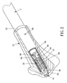
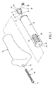
- the handlebar grip 10 comprises an outer tube 20, an inner tube 30, an elongated bolt 40, a wedge-shaped member 50, a grip layer 70 and a threadedly connecting structure 80.
- the outer tube 20 is an elongated cylindrical tube configured to serve as a structural support for the whole handlebar grip and made from a plastic material having a proper resilience by molding.
- the outer tube 20 has an open end 22 and a closed end 24 provided at a center thereof with a center hole 26.
- the inner tube 30 is also a cylindrical tube having a length smaller than that of the outer tube 20.
- the inner tube 30 is integrally formed with the outer tube 20 and extends axially from the inner surface of the closed end 24 of the outer tube 20 towards the open end 22. That is to say, the inner tube 30 and the outer tube 20 are coaxial to each other and the inner tube 30 has an outer diameter smaller than the inner diameter of the outer tube 20, such that an annular space 32 is defined between the inner tube 30 and the outer tube 20.
- the inner tube 30 is provided with three guide slots 34 extending along the axial direction of the inner tube 30 from the free end thereof toward the fixed end thereof at a predetermined length and being circumferentially equiangularly spaced at an angle of 120 degrees from each other. Further, the inner tube 30 is provided with a flared inner guide surface 36 extending from the free end thereof toward the fixed end thereof at a predetermined length, as shown in FIG. 3 . Furthermore, the outer circumferential surface of the inner tube 30 is provided with a plurality of axially extending teeth to enhance the clamping force exerting on the bicycle handlebar G.
- the elongated bolt 40 is composed of a head 42 and a threaded shank 44 extending longitudinally from the head 42. In assembly, the free end of the threaded shank 44 is inserted through the center hole 26 of the closed end 24 of the outer tube 20 into an inside of the inner tube 30.
- the wedge-shaped member 50 includes a proximity end 52, a distal end 54 having a diameter greater than that of the proximity end 52, and a flared circumferential surface 56 between the proximity end 52 and the distal end 54.
- the profile of the flared circumferential surface 56 is configured to be matched with that of the flared inner guide surface 36 in such a way that when the flared circumferential surface 56 is inserted into the inside of the inner tube 30 to a predetermined extent, the flared circumferential surface 56 will pressurize the circumferential wall of the inner tube 30 to expand outwardly.
- three ribs 58 are circumferentially equiangularly spaced at an angle of 120 degrees from each other.
- the wedge-shaped member 50 is positioned inside the outer tube 20 and screwingly threaded, by means of the threadedly connecting structure 80, with the threaded shank 44 of the elongated bolt 40 in such a way that the distal end 54 faces the open end 22 of the outer tube 20 and the three ribs 58 are respectively inserted into the guide slots 34.
- the threadedly connecting structure 80 is composed of an axially extending through hole 82 at the center of the wedge-shaped member 50, an open chamber 84 disposed inside the wedge-shaped member 50 and communicated with the through hole 82, and a nut 86 fixedly mounted in the open chamber 84, as shown in FIG. 4 .
- the threaded shank 44 of the elongated bolt 40 is inserted into the through hole 82 and screwingly threaded with the nut 86.
- the outer tube 20 can be covered with a material having a proper resilience, such as a grip layer 70 made from a rubber or plastic material.
- a grip layer 70 made from a rubber or plastic material.
- the grip layer 70 is provided at a closed end thereof with a through hole 72 through which the threaded shank 44 of the elongated bolt 40 passes.
- the outer tube 20 is sleeved onto the bicycle handlebar G through the open end 22 of the outer tube 20 in such a way that the anterior section of the handlebar G is inserted into the annular space 32.
- an additional retainer 90 may be provided to fix the open end 22 of the outer tube 20 on the handlebar G in advance.
- the retainer 90 is not a feature of the present invention; therefore, no detailed description thereof is necessarily outlined hereunder.
- a proper tool such as a hex key, is used to drive the elongated bolt 40 to rotate in a tightening up manner. Since the ribs 58 of the wedge-shaped member 50 are respectively inserted into the guide slots 34 of the inner tube 30, the wedge-shaped member 50 will not synchronously rotate along with the elongated bolt 40 but will be driven to axially and linearly move into the inside of the inner tube 30.
- the flared circumferential surface 56 with a gradually increased diameter will gradually contact and squeeze the flared inner guide surface 36, resulting in that the circumference wall of the inner tube 30 will be gradually forced to expand outwardly so as to firmly clamp the anterior section of the handlebar G, which is inserted in the annular space 32, between the inner tube 30 and the outer tube 20.
- the handlebar grip of the present invention is configured to have the inner tube, the outer tube and the annular space between the inner and outer tubes, the anterior section of the bicycle can be in one hand inserted into the annular space, and in the other hand be firmly clamped by the expanded circumferential wall of the inner tube when the circumferential wall of the inner tube is squeezed to outwardly expand.
- the guide slots provided by the inner tube can in one hand helpfully position the wedge-shaped member through the engagement of ribs of the wedge-shaped member with the guide slots, and in the other hand can provide a guiding effect to facilitate the smoothly and evenly outward expansion of the inner tube.
- the inner wall surface of the inner tube is provided with a guide surface matched with the outer circumferential surface of the wedge-shaped member, the inner tube can be smoothly expanded outwardly and the clamping force exerting on the anterior section of the bicycle handlebar can be determined by the location of the wedge-shaped member.
- the handlebar grip of the present invention can effectively improve the disadvantages of the prior arts.
Landscapes
- Engineering & Computer Science (AREA)
- Mechanical Engineering (AREA)
- Steering Devices For Bicycles And Motorcycles (AREA)
Applications Claiming Priority (1)
| Application Number | Priority Date | Filing Date | Title |
|---|---|---|---|
| TW100108822A TW201236912A (en) | 2011-03-15 | 2011-03-15 | Grip jacket assembly |
Publications (1)
| Publication Number | Publication Date |
|---|---|
| EP2500248A1 true EP2500248A1 (fr) | 2012-09-19 |
Family
ID=45715329
Family Applications (1)
| Application Number | Title | Priority Date | Filing Date |
|---|---|---|---|
| EP11172647A Withdrawn EP2500248A1 (fr) | 2011-03-15 | 2011-07-05 | Poignée de guidon |
Country Status (4)
| Country | Link |
|---|---|
| US (1) | US20120234130A1 (fr) |
| EP (1) | EP2500248A1 (fr) |
| CN (1) | CN102673709A (fr) |
| TW (1) | TW201236912A (fr) |
Cited By (2)
| Publication number | Priority date | Publication date | Assignee | Title |
|---|---|---|---|---|
| EP2840015B1 (fr) | 2013-08-22 | 2020-07-01 | Ergon International GmbH | Poignée de vélo |
| US10787220B2 (en) | 2014-05-19 | 2020-09-29 | Padloc, Llc | Handlebar and grip apparatus and system |
Families Citing this family (11)
| Publication number | Priority date | Publication date | Assignee | Title |
|---|---|---|---|---|
| TW201307138A (zh) * | 2011-08-12 | 2013-02-16 | Lee Chi Entpr Co Ltd | 自行車握把套 |
| US9630677B2 (en) * | 2012-06-15 | 2017-04-25 | Sram, Llc | Brake control apparatus |
| DE102012110074B4 (de) * | 2012-10-22 | 2019-01-24 | Klaus Mildenberger | Gefederter Fahrradgriff insbesondere in Flügelform |
| US9333818B2 (en) * | 2013-07-09 | 2016-05-10 | Roger De Torres | Method and system for storing and dispensing compressed air |
| JP6254497B2 (ja) * | 2013-10-11 | 2017-12-27 | 本田技研工業株式会社 | 鞍乗型車両の前部構造 |
| CN105197163A (zh) * | 2015-10-08 | 2015-12-30 | 重庆典果成实业有限公司 | 一种两轮车以及两轮车把手 |
| KR102005668B1 (ko) * | 2018-02-14 | 2019-07-30 | 이만호 | 2단분리 커버형 오토바이용 핸들밸런스 |
| US10766131B2 (en) | 2018-08-01 | 2020-09-08 | Alexander Deiser | Palmar grip |
| CN111452899B (zh) * | 2020-05-20 | 2021-12-14 | 湖州承峰智能科技有限公司 | 一种便于拆装的车把套结构 |
| KR20220095728A (ko) * | 2020-12-30 | 2022-07-07 | 현대자동차주식회사 | 퍼스널 모빌리티 |
| US11618526B2 (en) | 2021-01-29 | 2023-04-04 | Michael Perrone | Bicycle brake lever cap |
Citations (5)
| Publication number | Priority date | Publication date | Assignee | Title |
|---|---|---|---|---|
| US3964340A (en) * | 1975-05-19 | 1976-06-22 | Air Products And Chemicals, Inc. | Hand grip having an inner hub |
| EP0300980A2 (fr) * | 1987-07-24 | 1989-01-25 | SANDRO MENTASTI & C. S.A.S. | Poignée pour guidon |
| US6923089B2 (en) | 2003-01-06 | 2005-08-02 | International Bicycle Products Corporation | Handlebar grip |
| US6964214B2 (en) | 2003-01-09 | 2005-11-15 | International Bicycle Products Corporation | Handlebar grip for bicycle |
| US20060032326A1 (en) * | 2004-08-12 | 2006-02-16 | Lee Griswold | Locking bicycle handlebar grip |
Family Cites Families (3)
| Publication number | Priority date | Publication date | Assignee | Title |
|---|---|---|---|---|
| WO1994000699A1 (fr) * | 1992-06-24 | 1994-01-06 | D & D Group Pty Ltd | Dispositif d'engagement et element d'accouplement |
| CN201183579Y (zh) * | 2007-12-28 | 2009-01-21 | 宏汇工业股份有限公司 | 自行车把手构造 |
| CN201264688Y (zh) * | 2008-07-11 | 2009-07-01 | 温宜玲 | 前叉内管迫紧装置 |
-
2011
- 2011-03-15 TW TW100108822A patent/TW201236912A/zh unknown
- 2011-07-05 EP EP11172647A patent/EP2500248A1/fr not_active Withdrawn
- 2011-07-12 US US13/180,967 patent/US20120234130A1/en not_active Abandoned
-
2012
- 2012-01-29 CN CN2012100203172A patent/CN102673709A/zh active Pending
Patent Citations (5)
| Publication number | Priority date | Publication date | Assignee | Title |
|---|---|---|---|---|
| US3964340A (en) * | 1975-05-19 | 1976-06-22 | Air Products And Chemicals, Inc. | Hand grip having an inner hub |
| EP0300980A2 (fr) * | 1987-07-24 | 1989-01-25 | SANDRO MENTASTI & C. S.A.S. | Poignée pour guidon |
| US6923089B2 (en) | 2003-01-06 | 2005-08-02 | International Bicycle Products Corporation | Handlebar grip |
| US6964214B2 (en) | 2003-01-09 | 2005-11-15 | International Bicycle Products Corporation | Handlebar grip for bicycle |
| US20060032326A1 (en) * | 2004-08-12 | 2006-02-16 | Lee Griswold | Locking bicycle handlebar grip |
Cited By (3)
| Publication number | Priority date | Publication date | Assignee | Title |
|---|---|---|---|---|
| EP2840015B1 (fr) | 2013-08-22 | 2020-07-01 | Ergon International GmbH | Poignée de vélo |
| EP2840015B2 (fr) † | 2013-08-22 | 2025-01-22 | Ergon International GmbH | Poignée de vélo |
| US10787220B2 (en) | 2014-05-19 | 2020-09-29 | Padloc, Llc | Handlebar and grip apparatus and system |
Also Published As
| Publication number | Publication date |
|---|---|
| TW201236912A (en) | 2012-09-16 |
| US20120234130A1 (en) | 2012-09-20 |
| CN102673709A (zh) | 2012-09-19 |
Similar Documents
| Publication | Publication Date | Title |
|---|---|---|
| EP2500248A1 (fr) | Poignée de guidon | |
| US20060107802A1 (en) | Quick release device for releasing screw bit from socket | |
| TWI438046B (zh) | Clamping device for hollow shafts | |
| US8573878B2 (en) | Quick-release device | |
| EP2314502A3 (fr) | Ensemble réglable longitudinalement pour siège de bicyclette | |
| US6234506B1 (en) | Bicycle handlebar stem and front fork mounting arrangement | |
| TWI238796B (en) | Handlebar grip for transport vehicles | |
| US7712394B2 (en) | Handlebar grip | |
| KR101548111B1 (ko) | 관 연결 소켓 | |
| US6651918B2 (en) | Plastic film dispensing apparatus capable of adjusting tension of the film | |
| US8967170B1 (en) | Adjustable positioning structure for a walking stick | |
| JP4676478B2 (ja) | 自転車用部品装着構造 | |
| US6883818B1 (en) | Bicycle headset assembly | |
| US8234952B2 (en) | Handgrip for handlebar | |
| US20140311303A1 (en) | Screwdriver gripping tool | |
| US7389715B1 (en) | Pliers-type hand tool | |
| US8250714B2 (en) | Handgrip for handlebar | |
| US20070079578A1 (en) | Swiftly adjustable film packing device | |
| KR101794830B1 (ko) | 다단 파이프 고정구조 | |
| US9469367B2 (en) | Handlebar end caps for bicycle | |
| NO328491B1 (no) | Kobling | |
| CN112536753A (zh) | 多尺寸扳手及其转换装置 | |
| US20150211669A1 (en) | Fixing device for spoke sensor | |
| US20100101066A1 (en) | Device for attaching a rope to a handle | |
| US20050092127A1 (en) | Combination of bicycle headset assembly and head tube |
Legal Events
| Date | Code | Title | Description |
|---|---|---|---|
| PUAI | Public reference made under article 153(3) epc to a published international application that has entered the european phase |
Free format text: ORIGINAL CODE: 0009012 |
|
| AK | Designated contracting states |
Kind code of ref document: A1 Designated state(s): AL AT BE BG CH CY CZ DE DK EE ES FI FR GB GR HR HU IE IS IT LI LT LU LV MC MK MT NL NO PL PT RO RS SE SI SK SM TR |
|
| AX | Request for extension of the european patent |
Extension state: BA ME |
|
| STAA | Information on the status of an ep patent application or granted ep patent |
Free format text: STATUS: THE APPLICATION IS DEEMED TO BE WITHDRAWN |
|
| 18D | Application deemed to be withdrawn |
Effective date: 20130320 |