EP2500489A2 - Système de protection solaire - Google Patents
Système de protection solaire Download PDFInfo
- Publication number
- EP2500489A2 EP2500489A2 EP12154230A EP12154230A EP2500489A2 EP 2500489 A2 EP2500489 A2 EP 2500489A2 EP 12154230 A EP12154230 A EP 12154230A EP 12154230 A EP12154230 A EP 12154230A EP 2500489 A2 EP2500489 A2 EP 2500489A2
- Authority
- EP
- European Patent Office
- Prior art keywords
- awning
- cassette
- drop rail
- sunshade
- arms
- Prior art date
- Legal status (The legal status is an assumption and is not a legal conclusion. Google has not performed a legal analysis and makes no representation as to the accuracy of the status listed.)
- Withdrawn
Links
Images


Classifications
-
- E—FIXED CONSTRUCTIONS
- E04—BUILDING
- E04F—FINISHING WORK ON BUILDINGS, e.g. STAIRS, FLOORS
- E04F10/00—Sunshades, e.g. Florentine blinds or jalousies; Outside screens; Awnings or baldachins
- E04F10/02—Sunshades, e.g. Florentine blinds or jalousies; Outside screens; Awnings or baldachins of flexible canopy materials, e.g. canvas ; Baldachins
- E04F10/06—Sunshades, e.g. Florentine blinds or jalousies; Outside screens; Awnings or baldachins of flexible canopy materials, e.g. canvas ; Baldachins comprising a roller-blind with means for holding the end away from a building
- E04F10/0611—Sunshades, e.g. Florentine blinds or jalousies; Outside screens; Awnings or baldachins of flexible canopy materials, e.g. canvas ; Baldachins comprising a roller-blind with means for holding the end away from a building with articulated arms supporting the movable end of the blind for deployment of the blind
- E04F10/0618—Sunshades, e.g. Florentine blinds or jalousies; Outside screens; Awnings or baldachins of flexible canopy materials, e.g. canvas ; Baldachins comprising a roller-blind with means for holding the end away from a building with articulated arms supporting the movable end of the blind for deployment of the blind whereby the pivot axis of the articulation is perpendicular to the roller
-
- E—FIXED CONSTRUCTIONS
- E04—BUILDING
- E04F—FINISHING WORK ON BUILDINGS, e.g. STAIRS, FLOORS
- E04F10/00—Sunshades, e.g. Florentine blinds or jalousies; Outside screens; Awnings or baldachins
- E04F10/02—Sunshades, e.g. Florentine blinds or jalousies; Outside screens; Awnings or baldachins of flexible canopy materials, e.g. canvas ; Baldachins
- E04F10/06—Sunshades, e.g. Florentine blinds or jalousies; Outside screens; Awnings or baldachins of flexible canopy materials, e.g. canvas ; Baldachins comprising a roller-blind with means for holding the end away from a building
- E04F10/0611—Sunshades, e.g. Florentine blinds or jalousies; Outside screens; Awnings or baldachins of flexible canopy materials, e.g. canvas ; Baldachins comprising a roller-blind with means for holding the end away from a building with articulated arms supporting the movable end of the blind for deployment of the blind
-
- E—FIXED CONSTRUCTIONS
- E04—BUILDING
- E04F—FINISHING WORK ON BUILDINGS, e.g. STAIRS, FLOORS
- E04F10/00—Sunshades, e.g. Florentine blinds or jalousies; Outside screens; Awnings or baldachins
- E04F10/02—Sunshades, e.g. Florentine blinds or jalousies; Outside screens; Awnings or baldachins of flexible canopy materials, e.g. canvas ; Baldachins
- E04F10/06—Sunshades, e.g. Florentine blinds or jalousies; Outside screens; Awnings or baldachins of flexible canopy materials, e.g. canvas ; Baldachins comprising a roller-blind with means for holding the end away from a building
- E04F10/0692—Front bars
- E04F10/0696—Front bars with means to attach an auxiliary screen
Definitions
- the invention relates to an awning with additional sun protection and an additional sun protection for an awning.
- the awning comprises a frame pivotable about a horizontal axis. Between the frame and the building ropes are stretched, on which run eyelets, which carry a curtain.
- the utility model G 84 30 086 U1 discloses an awning with a fabric and an associated support to which the fabric is anchored.
- the carrier is formed by a cylinder profile with two longitudinal bores. The longitudinal bores are slotted towards the cylinder jacket.
- the awning material is anchored with a piping in one of these holes. The other hole may carry a vertically hanging curtain.
- the DE 37 44 590 C1 discloses an awning with obliquely arranged rails, on which support rods of a fabric curtain are suspended movably along the rails.
- the mounting rails carry the fabric curtain, which is initially horizontal or light along the mounting rails sloping downwards and then hanging down from the free end of the mounting rails down.
- the DE 200 09 461 U1 discloses an anti-glare curtain formed in the manner of a vertically oriented articulated arm awning. From a vertically oriented winding shaft, an anti-glare curtain extends like a wall to a vertical Ausschubstab whose lower end is supported by a wheel on the ground. Between the housing of the winding shaft and the extension rod articulated arms are arranged.
- the DE 1 896 00 U1 discloses a sunshade that is to be moved vertically in front of a window and, if necessary, to fold on a circular arc away from it.
- a side awning which includes an arm to be folded away from a house wall about a vertical axis.
- This arm carries a curtain, for example in the form of a Roman blind.
- awnings and possibly an additional sunscreen is a persistent problem.
- Several different requirements have to be united with each other, whose individual solutions lead in different directions.
- the system is designed to be easy to use, easy to retrofit, and robust.
- the removal of the awning fabric under the action of a spring bias may be resiliently biased away from the building.
- the winding shaft may be provided with a manual drive or a motor drive which rotates the winding shaft in the winding or in the unwinding direction.
- the guide profile has a rectangular guide channel, for example, in which one or more rollers of the awning arms run.
- the guide profile may be a longitudinally slotted rectangular hollow profile.
- the basic concept of the awning arms swiveling away from the building approximately horizontally provides a simple and clear, yet robust, basic structure, with which the awning fabric can be taut without any problem. Even with moderate spring forces the drop rail can absorb high Tuchzug material. When the angle included between the drop rail and the awning arms approaches a right angle, despite decreasing, acting on the awning arms Swinging moment ever greater Tuchzug will be absorbed.
- the storage of the ends of the awning arms in or on the drop rail by wheels or rollers avoids unnecessary friction and thus facilitates the complete swinging out of the awning arms despite relatively low, easily manageable spring forces.
- the awning can be equipped with an additional sunscreen.
- This can for example be attached to the drop rail or on the awning arm.
- it is housed in a cassette housing, wherein the cassette housing preferably has only at its two end faces fastening devices for attachment to the awning.
- This concept allows the variable use of the sunshade alternatively on the drop rail or on the awning arm. This in particular if the fastening devices allow a certain pivotal movement of the cassette against its associated suspension, at least in principle. While one end of the cassette is located at the pivotal mounting at a fixed height, the other end of the cassette can pivot up and down.
- the cassette can be attached to the in use and in the building-splayed state, preferably slightly obliquely downwardly extending, awning arm, wherein one of the ends of the cassette is pivotable and the other Height adjustable is mounted on the awning arm.
- For height adjustment can serve a lockable spring winding apparatus, which has been found to be particularly user-friendly.
- the cassette according to the invention can, in particular by the nature of its attachment optionally on the drop rail or on the preferably rigid, i. hingeless awning arms are attached.
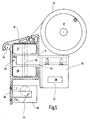
- awning 11 which carries an additional sunshade 12. This is, as easily recognizable, attached laterally. Additional additional sunshades 13, 14 may be attached to the end of the awning 11 away from the building wall 10. While the awning 11 extends approximately horizontally or slightly sloping away from the building wall 10, to overshadow a place, such as a seat, appropriate cloths or sheets of additional sunscreen 12, 13, 14, preferably vertically from the awning 11 down.
- the near-building end 16 is fixed to a winding shaft 17.
- the other end 18 is attached to a drop rail 19, e.g. taken in a corresponding Kedernut.
- the drop rail 19 is preferably arranged horizontally and parallel to the winding shaft 17.
- the drop rail 19 is made of, for example FIG. 3 visible awning arms 20, 21 worn, which is taken on the building wall 10 in corresponding bearings 22, 23 and pivotally mounted about a vertical or slightly inclined to the vertical axis of rotation 24.
- the bearing 22 is arranged below a winding shaft 17 receiving awning box 25. It may be connected to the building wall 10 and / or the awning box 24.
- the awning box 24 and the storage for the awning arms 20, 21 form a structural unit that is hung in pre-assembled consoles.
- FIG. 4 illustrates the storage 22 separately.
- the awning arm 20 is biased by a spring 55 in the pivoting direction away from the wall 10.
- the spring 55 may be a tension spring, which is outside the pivot axis 24 engages an end piece 56 of the arm 20 and thus generates a pivoting moment for the awning arm 20 (21).
- roller assembly 26, 27, in FIG. 1 indicated schematically and better off FIG. 5 is apparent. It comprises at least one, preferably at least two rollers 28, 29, which are preferably rotatably mounted about an approximately perpendicular axis 30. They are supported by a tab 31 extending from the end of the awning arm 20, 21 away from the respective support 22, 23.
- the drop rail 19 is formed as a guide profile. For this purpose, it has, for example, a longitudinally extending through the drop rail 19 interior 32, which, as shown, may be rectangular or otherwise shaped. He is on its building wall 10 facing side accessible through a slot 33 through which the tab 31 extends therethrough.
- the roller assembly 26 is preferably disposed in the interior 32 and may run along the drop rail 19. The vertical boundary walls of the interior 32 form tracks for the rollers 27, 28th
- the tab 31 is preferably part of a fitting 34, for example made of metal, which is attached to the free end of the awning arm 20 (or 21).
- the fitting 34 is separately in FIGS. 6 and 7 illustrated. As can be seen, it may have a downwardly extending extension 35, which may serve to secure the additional sunshade 12.
- an opening 36 may be formed in the extension 35, for example in the form of a rectangular slot.
- the opening 36 at the bottom limiting web 37 is in cross section (see FIG. 7 ) is preferably rounded, for example circular. He is horizontal arranged and thereby formed a horizontal pivot bearing for the additional sun protection 12th
- a downwardly extending extension 38 which is also the storage of an additional sunscreen (13,14 in FIG. 2 ) serves.
- This extension 38 may be formed, for example, as a straight extension of the front wall of the interior 32 down.
- one or more brackets 39 may be screwed, which serve to receive the respective sunshade 13 or 14 and to have a slot-like passage 40.
- An end-side end piece of the drop rail 19 can also serve as a support for mounting the sunshade 13 or 14.
- a Kedernut 41 for receiving the in FIG. 2 schematically indicated flounces 42.
- the additional sunshade 12 preferably coincides with the sunshade 13, 14.
- the uniform sunshade 12, 13, 14 can optionally be attached to the drop rail 19 or the awning arms 20, 21.
- the following description of the sunshade 12 applies equally to the other sunshades 13 and 14.
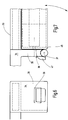
- FIGS. 7 and 8th shows a cassette 43, which is designed as a hollow box, as a closed end tube profile or downwardly open U-profile.
- a winding shaft 44 is housed with a wound roller blind is provided and forms a downwardly extendable roller blind.
- other shading means such as a horizontal or vertical blind slat curtain, a folding blind or the like may be accommodated in the cassette 43.
- the cassette 43 is only at its two ends 45, 46 ( FIGS. 7 and 8th ) provided with fastening means 47, 48, preferably in the form downwardly curved hook.
- the hooks are preferably formed by downwardly curved flat profiles with a rectangular cross-section.
- the rectangular cross section corresponds to a necessary clearance the cross section of the opening 36th
- the hook 48 While the hook 47 is hooked into the opening 36 of the fitting 34, the hook 48 is connected to a height-adjustable suspension 49.
- a receiving lug 50 in which the hook 48 engages, wherein the suspension lug 50 is supported by a pulling means 51.
- the traction means 51 may be a rope, a wire or a band, for example a plastic band or preferably a steel band.
- This is a, for example, arranged on the awning arm 20 or 22 winding device 52 assigned, this meadow by means of a locking device is preferably blockable. It has a take-up reel 53, which is biased by a not further illustrated spring in the winding direction.
- a release button 54 may be provided to release the locking device to allow rotation of the reel spool 53.
- the locking device may be formed by a slider which acts on the reel spool 53 to lock it.
- the trigger button 54 may be manually operable.
- the winding moment acting on the reel spool 53 is so great that the tensile force on the traction means 51 is the weight of the sunshade 12 easily overcomes.
- the force exerted by the awning arms 20, 21 on the drop rail 19 away from the building wall 10 force increases despite decreasing spring force due to the change in angle of the angle between the awning arms and the drop rail or remains at least constant.
- the awning 1 is extended. This condition is in the Figures 1 and 2 illustrated. It can now be activated, for example, the additional lateral sunshade 12.
- FIG. 8 first brought the cassette 43 in horizontal position. It is sufficient to pull the cartridge 12 at its building end down. A built-in cassette 43 spirit level can facilitate the horizontal adjustment of the cassette 12. Once the horizontal position has been reached, the blind placed in the cassette 43, for example a blind or the like, can be extended.
- the awning can be retracted at any time. If the lateral sunshade 12 is still in the pull-out position, it does not hinder the retraction of the awning. Thus, for example, a motor-operated awning can be retracted automatically at any time, without causing damage or danger.
- the winding device 52 it is possible by the winding device 52 to find a particularly secure stowed position.
- the curtain for example, the blind, wound on the winding shaft 44.
- the sunscreen of the sunscreen 12 is thus completely absorbed by the cartridge 43 as possible.
- the trigger button 54 is actuated.
- the reel spool 53 is released and the right end 46 of the cassette 43 is pulled upward until it abuts against the awning arm 20 or 22.
- the awning 10 can now be retracted by winding up the awning fabric 15 as described above.
- the awning according to the invention has two awning arms, which are held on the drop rail in linear guides.
- a sunshade 12, 13, 14 is provided, the cartridge housing is held only at its two ends 45, 46 by suitable fastening means.
- at least one of the two ends about a horizontal axis (web 37) is pivotally supported, while the other end 46 can be adjusted by a height-adjustable suspension 49 up or down.
- the operation is very easy and safe.
Landscapes
- Engineering & Computer Science (AREA)
- Architecture (AREA)
- Civil Engineering (AREA)
- Structural Engineering (AREA)
- Building Awnings And Sunshades (AREA)
Applications Claiming Priority (1)
| Application Number | Priority Date | Filing Date | Title |
|---|---|---|---|
| DE102011000653A DE102011000653A1 (de) | 2011-02-11 | 2011-02-11 | Sonnenschutzsystem |
Publications (1)
| Publication Number | Publication Date |
|---|---|
| EP2500489A2 true EP2500489A2 (fr) | 2012-09-19 |
Family
ID=45560813
Family Applications (1)
| Application Number | Title | Priority Date | Filing Date |
|---|---|---|---|
| EP12154230A Withdrawn EP2500489A2 (fr) | 2011-02-11 | 2012-02-07 | Système de protection solaire |
Country Status (2)
| Country | Link |
|---|---|
| EP (1) | EP2500489A2 (fr) |
| DE (1) | DE102011000653A1 (fr) |
Citations (5)
| Publication number | Priority date | Publication date | Assignee | Title |
|---|---|---|---|---|
| DE1896000U (de) | 1961-06-19 | 1964-07-02 | Marcel Andre Belin | Sonnenvorhang. |
| DE3315504A1 (de) | 1983-04-28 | 1985-04-18 | Bernhard Dipl.-Ing. 8434 Berching Benkendorff | Schwenkrahmen fuer markise - antrieb und seitenvorhang - |
| DE3744590C1 (de) | 1987-12-31 | 1989-09-14 | Clauss Markisen | Schraegmarkise mit anschliessendem vertikalem Bereich |
| DE20009461U1 (de) | 2000-05-25 | 2000-11-02 | Gerhardt, Roland, 35759 Driedorf | Motorisch angetriebener Blendschutzvorhang |
| DE20209746U1 (de) | 2002-06-24 | 2002-09-26 | Behr, Karl-Günter, Dipl.-Ing., 35444 Biebertal | Einrichtung zur Aufnahme einer Seitenmarkise als Sicht- und Sonnenschutz |
Family Cites Families (2)
| Publication number | Priority date | Publication date | Assignee | Title |
|---|---|---|---|---|
| DE189600C (fr) | ||||
| DE8430086U1 (de) | 1984-10-12 | 1985-01-31 | Möbius, Wolf, 2070 Ahrensburg | Markise |
-
2011
- 2011-02-11 DE DE102011000653A patent/DE102011000653A1/de not_active Withdrawn
-
2012
- 2012-02-07 EP EP12154230A patent/EP2500489A2/fr not_active Withdrawn
Patent Citations (5)
| Publication number | Priority date | Publication date | Assignee | Title |
|---|---|---|---|---|
| DE1896000U (de) | 1961-06-19 | 1964-07-02 | Marcel Andre Belin | Sonnenvorhang. |
| DE3315504A1 (de) | 1983-04-28 | 1985-04-18 | Bernhard Dipl.-Ing. 8434 Berching Benkendorff | Schwenkrahmen fuer markise - antrieb und seitenvorhang - |
| DE3744590C1 (de) | 1987-12-31 | 1989-09-14 | Clauss Markisen | Schraegmarkise mit anschliessendem vertikalem Bereich |
| DE20009461U1 (de) | 2000-05-25 | 2000-11-02 | Gerhardt, Roland, 35759 Driedorf | Motorisch angetriebener Blendschutzvorhang |
| DE20209746U1 (de) | 2002-06-24 | 2002-09-26 | Behr, Karl-Günter, Dipl.-Ing., 35444 Biebertal | Einrichtung zur Aufnahme einer Seitenmarkise als Sicht- und Sonnenschutz |
Also Published As
| Publication number | Publication date |
|---|---|
| DE102011000653A1 (de) | 2012-08-16 |
Similar Documents
| Publication | Publication Date | Title |
|---|---|---|
| EP0322534B1 (fr) | Store incliné | |
| DE29815953U1 (de) | Lüftungsvorrichtung zur Anordnung in einem Wandflächenbereich eines Stallgebäudes | |
| EP0119550B1 (fr) | Toit en pavillon repliable, en particulier store à bannes auvent de tente pour caravanes et similaire | |
| EP1936105B1 (fr) | Pare-soleil vertical | |
| EP2535501B1 (fr) | Dispositif d'ombrage de bâtiments doté de rails de guidage pouvant être sortis | |
| DE4021264C2 (de) | Schrägmarkise | |
| DE3607944C2 (fr) | ||
| EP3054063B2 (fr) | Marquise comprenant des rails de guidage abaissables | |
| DE202007017061U1 (de) | Universell einsetzbarer Rahmen für Vorhänge oder Rollos | |
| EP2500489A2 (fr) | Système de protection solaire | |
| DE19621956B4 (de) | Markise mit zwangsläufig bewegtem Volant | |
| DE29902888U1 (de) | Fenster- oder Türanordnung an Wohnwagen, Wohnmobilen oder sonstigen Fahrzeugen | |
| DE19814577C1 (de) | Sonnenschutzanlage | |
| DE202009009925U1 (de) | Gelenkarmmarkise mit zusätzlichem Sonnenschutz | |
| CH650305A5 (de) | Markise. | |
| DE102010017729A1 (de) | Sicht- und Sonnenschutz für Markisen | |
| AT11824U1 (de) | Vertikal sowie horizontal verbaubares rollosystem, insbesondere insektenschutzgitter-rollosystem, mit geringer bautiefe | |
| DE2549935A1 (de) | Abdeckvorrichtung fuer verschwenkbare dachflaechenfenster | |
| DE2527382C3 (de) | Schutzabdeckung für verschwenkbare Dachflächenfenster | |
| EP3027835B1 (fr) | Système d'ombrage motorisé | |
| DE3246353A1 (de) | Sonnenschutz-vorrichtung | |
| DE202006021144U1 (de) | Senkrechtbeschattung | |
| DE4141543C1 (en) | External roller shutter for windows and doors - has winder in housing with handle, by which pull belt can be pulled through aperture in frame or wall | |
| DE202007009717U1 (de) | Anordnung mit einer Beschattungseinrichtung für ein lichtdurchlässiges Flächenelement | |
| EP1780350B1 (fr) | Store à rappel positif |
Legal Events
| Date | Code | Title | Description |
|---|---|---|---|
| PUAI | Public reference made under article 153(3) epc to a published international application that has entered the european phase |
Free format text: ORIGINAL CODE: 0009012 |
|
| AK | Designated contracting states |
Kind code of ref document: A2 Designated state(s): AL AT BE BG CH CY CZ DE DK EE ES FI FR GB GR HR HU IE IS IT LI LT LU LV MC MK MT NL NO PL PT RO RS SE SI SK SM TR |
|
| AX | Request for extension of the european patent |
Extension state: BA ME |
|
| STAA | Information on the status of an ep patent application or granted ep patent |
Free format text: STATUS: THE APPLICATION IS DEEMED TO BE WITHDRAWN |
|
| 18D | Application deemed to be withdrawn |
Effective date: 20160901 |